EP1460497A2 - Sicherheitssteuerung - Google Patents
Sicherheitssteuerung Download PDFInfo
- Publication number
- EP1460497A2 EP1460497A2 EP04002817A EP04002817A EP1460497A2 EP 1460497 A2 EP1460497 A2 EP 1460497A2 EP 04002817 A EP04002817 A EP 04002817A EP 04002817 A EP04002817 A EP 04002817A EP 1460497 A2 EP1460497 A2 EP 1460497A2
- Authority
- EP
- European Patent Office
- Prior art keywords
- safety
- input
- output
- signals
- systems
- Prior art date
- Legal status (The legal status is an assumption and is not a legal conclusion. Google has not performed a legal analysis and makes no representation as to the accuracy of the status listed.)
- Granted
Links
Images


Classifications
-
- G—PHYSICS
- G05—CONTROLLING; REGULATING
- G05B—CONTROL OR REGULATING SYSTEMS IN GENERAL; FUNCTIONAL ELEMENTS OF SUCH SYSTEMS; MONITORING OR TESTING ARRANGEMENTS FOR SUCH SYSTEMS OR ELEMENTS
- G05B19/00—Programme-control systems
- G05B19/02—Programme-control systems electric
- G05B19/04—Programme control other than numerical control, i.e. in sequence controllers or logic controllers
- G05B19/05—Programmable logic controllers, e.g. simulating logic interconnections of signals according to ladder diagrams or function charts
- G05B19/058—Safety, monitoring
-
- G—PHYSICS
- G05—CONTROLLING; REGULATING
- G05B—CONTROL OR REGULATING SYSTEMS IN GENERAL; FUNCTIONAL ELEMENTS OF SUCH SYSTEMS; MONITORING OR TESTING ARRANGEMENTS FOR SUCH SYSTEMS OR ELEMENTS
- G05B2219/00—Program-control systems
- G05B2219/10—Plc systems
- G05B2219/11—Plc I-O input output
- G05B2219/1109—Expansion, extension of I-O
-
- G—PHYSICS
- G05—CONTROLLING; REGULATING
- G05B—CONTROL OR REGULATING SYSTEMS IN GENERAL; FUNCTIONAL ELEMENTS OF SUCH SYSTEMS; MONITORING OR TESTING ARRANGEMENTS FOR SUCH SYSTEMS OR ELEMENTS
- G05B2219/00—Program-control systems
- G05B2219/10—Plc systems
- G05B2219/14—Plc safety
- G05B2219/14114—Integrity, error detector, switch off controller, fail safe
Definitions
- the present invention relates to a safety controller preferable for construction of a safety system (safety operation system) in a factory, particularly to a safety controller set between various safety switches and production equipment which may be a dangerous source to execute the control for avoiding a state in which a worker is exposed to danger.
- a safety controller preferable for construction of a safety system (safety operation system) in a factory, particularly to a safety controller set between various safety switches and production equipment which may be a dangerous source to execute the control for avoiding a state in which a worker is exposed to danger.
- various safety controllers are used.
- the basic function of this type of safety controllers executes the control for stopping production equipment by determining a state in which a worker is exposed to danger between various types of safety switches (e.g. emergency stop switch, two-hand-control switch, mat switch, safety limit switch, light curtain, and electromagnetically-locking safety door switch) and production equipment (robot arm, machine tool, and conveyer).
- safety switches e.g. emergency stop switch, two-hand-control switch, mat switch, safety limit switch, light curtain, and electromagnetically-locking safety door switch
- production equipment robot arm, machine tool, and conveyer
- a safety PCL (Programmable Logic Controller) and a safety relay unit are known as conventional safety controllers.
- the safety PLC is a controller whose operation reliability is improved compared to a normal PLC by duplexing hardware and software or adding a troubleshooting function.
- the safety relay unit is a unit having a built-in exclusive safety relay set between a safety switch and production equipment.
- a safety relay unit is conventionally known which can be applied to various types of safety switches by automatically recognizing the type of a connected safety switch and changing a program to a corresponding operation program (for example, refer to Patent Document 1).
- Patent Document 1 is National Publication of International Patent Application No. 2001-521669.
- the safety PLC is basically a PLC
- the above mentioned is very troublesome because it is necessary to obtain an approval on whether the safety standard is satisfied whenever installation of an operation program in the safety PLC is completed when installing the program in equipment to be exported to Europe which requests a severe safety standard.
- the added operation programs are newly approved by the safety standard. Therefore, the same problem as described above occurs.
- the safety relay unit In the case of the safety relay unit, an operation for prescribing the relation between a signal input from a safety switch and a signal output to a dangerous source is fixed in hardware or software. Therefore, if the unit is approved by the safety standard when the unit is shipped, it is not necessary that the unit is repeatedly approved by the standard when installation of the unit in an actual safety system is completed.
- an exclusive unit is necessary every type of safety switch, it is necessary to purchase an exclusive safety relay unit every type of switch in order to correspond to a safety system including various types of safety switches. Thus, ordering is troublesome and stock management requires a lot of time and the cost will be increased.
- the safety relay unit having a built-in CPU and being able to be applied to various types of safety switches described in Patent Document 1 can be applied to only one safety switch, a plurality of safety switches respectively having a built-in CPU is necessary in order to correspond to a safety system including a plurality of safety switches and therefore, the cost will be extremely increased.
- the present invention is made to solve the above problems and its object is to provide a safety controller which is able to set a necessary operation program to any type of safety switch as long as the switch is any one of a plurality of predetermined safety switches and moreover which does not have to obtain a safety standard approval whenever it is built in a safety system when it is exported to Europe.
- a safety controller of the present invention has a basic module, one or more expansion modules, and a mother board provided with an expansion slot for connecting the modules by a bus.
- An input expansion module which is one of the expansion modules includes one or more external input terminal sections capable of connecting one or more safety switches and an input circuit for receiving safety signals from one or more external terminal sections.
- a "safety switch” denotes a switch or sensor for detecting a state when a person approaches an apparatus or machine which is a dangerous source or stopping the machine.
- a safety switch, emergency stop switch, two-hand-control switch, tape switch, and light curtain correspond to the switch or sensor.
- These safety switches are respectively provided with a fail-safe function or troubleshooting function and the safety or reliability of them is improved by multiplexing hardware or software. The number of terminals or the terminal arrangement of each of these safety switches depends on the type of the terminals.
- the input circuit includes a circuit configuration capable of transmitting or receiving a desired signal to or from each external terminal even if any predetermined type of safety switches is connected.
- An output expansion module which is one of the expansion modules includes an external output terminal section which can be connected to the output control system of a dangerous source and an output circuit for transmitting a safety output signal to the external output terminal section.
- the "output control system of the dangerous source” denotes the control circuit of a magnet switch (such as magnet contactor: electromagnetic contactor) for turning on/off a driving source such as one of a robot arm, machine tool, and conveyer which are dangerous sources.
- the number of units or devices to be connected to an external output terminal section is not restricted to one. Therefore, a necessary number of external output terminals are prepared for the external output terminal section in accordance with an assumed output control system.
- An output device constituting an output circuit can use not only an electromagnetic relay but also a solid-state relay (SSR) having a built-in semiconductor switching device. The number of these output devices is properly decided in accordance with the number of external output terminals.
- SSR solid-state relay
- the basic module includes operation program storing part for storing a safety operation program for defining the relation between the state of a safety input signal and the state of a safety output signal every predetermined type of safety switch, type-of-switch setting part for setting an external input terminal section and the type of safety switch to be connected to the external input terminal section, and operation program executing part for selecting a safety operation program corresponding to the type of switch set by the setting part among a plurality of types of safety operation programs stored in the operation program storing part and executing the selected program for the external input terminal section set by the setting part.
- operation program storing part for storing a safety operation program for defining the relation between the state of a safety input signal and the state of a safety output signal every predetermined type of safety switch
- type-of-switch setting part for setting an external input terminal section and the type of safety switch to be connected to the external input terminal section
- operation program executing part for selecting a safety operation program corresponding to the type of switch set by the setting part among a plurality of types of
- the "safety operation program” denotes, in short, a program for realizing operations for determining the operation state (on-state/off-state) of each of safety switches connected to one or more external input terminal sections correspondingly to the configuration of each safety switch, generating a final output state by applying these determination results to a specified logic, and transmitting the final output state to the unit or device connected to each external terminal of the external output terminal section.
- the driving source such as motor
- the safety operation program concerned is automatically executed. Therefore, only by connecting a safety switch and an output device or unit to the external input terminal section or external output terminal section concerned, it is possible to easily and quickly construct a desired safety system without preparing a safety operation program like the case of a safety PLC. Moreover, because a specified program is used as a safety operation program, by obtaining the approval of a safety standard once when the program is shipped from the factory, it is thereafter unnecessary to newly obtain a safety-standard approval even if any safety system is constructed. Therefore, it is possible to smoothly export the program to Europe which requires a safety-standard approval. Furthermore, when constructing a safety system including many safety switches or expanding an existing safety system, it is only necessary to expand an expansion module and then perform the same setting operation. Therefore, there is an advantage that a very high expansion flexibility of a system is obtained.
- an emergency stop switch is included as a predetermined type of safety switch, and a safety operation program corresponding to the emergency stop switch executes;
- a mat switch is included as a predetermined type of safety switch
- a two-hand-control switch is included as a predetermined type of safety switch, and a safety operation program corresponding to the two-hand-control switch executes;
- a light curtain is included as a predetermined type of safety switch, and a safety operation program corresponding to the light curtain executes;
- the basic module includes one or more external input terminal sections capable of connecting one or more safety switches, an input circuit for receiving safety input signals from one or more external input terminal sections, an external output terminal section which can be connected to the output control system of a dangerous source, and an output circuit for transmitting a safety output signal to the external output terminal section. According to the above configuration, it is possible to construct a safety system even by only the basic unit.
- the basic module includes part for executing a diagnostic program for diagnosing whether a predetermined expansion module is set to each expansion slot by collating the module identifying information read from an expansion slot on a mother board with the module identifying information set to the basic module. According to the above configuration, it is possible to avoid the risk of a malfunction caused by setting a not-predetermined expansion module to an expansion slot.
- the basic module further includes troubleshooting-program storing part for storing a troubleshooting program for troubleshooting a safety switch connected to an external connection terminal section every type of predetermined safety switch and troubleshooting-program executing part for selecting a troubleshooting program corresponding to the type of a switch set by setting part and executing the selected troubleshooting program for the external input terminal section set by the setting part.
- a troubleshooting program of an electromagnetically-locking door switch having an unlocking solenoid includes a solenoid diagnostic function for diagnosing a trouble of the unlocking solenoid. According to the above configuration, it is possible to improve the reliability of the door switch by securing the operational reliability of the unlocking solenoid.
- a troubleshooting program includes a history generating function for making it possible to diagnose the contact deterioration of a safety switch in accordance with the aging of the time difference between signals of two systems coming from a pair of interlocking contacts included in the safety switch. According to the above configuration, it is possible to automatically diagnose the contact deterioration of the safety switch.
- a troubleshooting program includes a history generating function for making it possible to diagnose the contact deterioration of a contactor in accordance with the aging of the time difference until a feedback signal arrives from a contactor auxiliary contact after transmitting a safety output signal. According to the above configuration, it is possible to automatically diagnose the contact deterioration of the contactor.
- the basic module includes output-monitoring-program executing part for monitoring the state of a contactor constituting the output control system of a dangerous source in accordance with a contactor auxiliary-contact signal received from a feedback input terminal set to the basic module or an expansion module. According to the above configuration, it is possible to confirm whether the contactor is correctly operated after transmitting a safety output signal.
- the basic module includes interlocking-program executing part for controlling the propriety of an output operation which is an execution result of the safety operation program in accordance with a PLC operation state signal received from a PLC operation state input terminal set to the basic module or an expansion module.
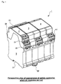
- Fig. 1 shows a perspective view of the appearance of a safety controller when all modules are set
- Fig. 2 shows a perspective view of the appearance of the safety controller when expansion modules are removed from the safety controller
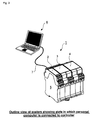
- Fig. 3 shows the appearance of a system when a personal computer is connected to the controller.
- a safety controller 1 is provided with a basic module 2, input expansion module 3, and output expansion module 4. These modules 2, 3, and 4 are aligned, positioned, and fixed through a module holder 5.
- the module holder 5 is a boxy housing whose upside is opened and a DIN-rail setting groove 51 and a DIN-rail securing attachment 52 are set to the bottom of the housing. Therefore, the module holder 5 can be set to a not-illustrated DIN rail.
- the illustrated example shows a case of setting two expansion modules 3 and 4 to one basic module. However, it is also allowed to further increase the number of expansion modules so that many expansion modules such as 8 or 16 modules can be set.
- the basic module 2, input expansion module 3, and output expansion module 4 can be inserted into a basic-module connector 531 and expansion-module connectors 533-1 to 533-n on the mother board 53.
- a first input terminal block 21 and a second input terminal block 22 are set to one side of the basic module 2 at two stages of top and bottom and a first output terminal block 23 and a second output terminal block 24 are set to the other side of the basic module 2 at two stages of top and bottom.
- a first input terminal block 31, second input terminal block 32, third input terminal block 33, and fourth input terminal block 34 are set to the other side of the input expansion module 3 at two stages of top and bottom.
- a first output terminal block 41 is set to one side of the output expansion module 4 and a second output terminal block 42 is set to the other side of the output expansion module 4.
- each terminal block can be connected to each terminal block and an electric wire constituting each signal line can be easily fixed through a core-plug-in-type clamper mechanism.
- the basic module 2 constituting the safety controller 1 can be communicated with a personal computer 6 through an RS-232C cord 7, various setting operations to be described later are performed through the keyboard of the personal computer 6, and the set data thus obtained is written in a memory (such as EEPROM) of the basic module 2 constituting the safety controller 1 through the RS-232C cord 7. Because this type of data communication and memory writing are publicly known by various types of documents, detailed description is omitted.
- Figs. 1 to 3 show examples of setting one basic module 2 and two expansion modules 3 and 4.
- the number of and the type of the expansion modules are not restricted to the examples in Figs. 1 to 3.
- Fig. 4 is a block diagram showing a hardware configuration of a basic module.
- the basic module 2 includes a first CPU 201, second CPU 202, first input circuit 203, second input circuit 204, first output circuit 205, second output circuit 206, communication circuit (RS-232C) 207, and power circuit 208.
- RS-232C communication circuit
- the first CPU 201 and second CPU 202 are used to achieve duplexing of control and respectively execute almost the same program.
- the first CPU 201 stores a program memory (such as flash memory) 202a for storing a safety operation program to be described later.
- the second CPU 202 stores a program memory 202b for storing a safety operation program to be described later.
- EEPROMs 209a and 209b for storing various set data values to be described later are set to outsides of the first CPU 201 and second CPU 202 respectively.
- the stored content of the program memory 202a is almost the same as that of the program memory 202b and also the stored content of the EEPROM 209a is almost the same as that of the EEPROM 209b.
- a safety switch 9 to be described later is connected to the first input circuit 203 and second input circuit 204 and an electromagnetic contactor (magnet contactor: magnet switch) 10 is connected to the first output circuit 205 and second output circuit 206 in the case of this example.
- the personal computer (PC) 6 is connected to the communication circuit (RS-232C) 207 and an external power supply 8 is connected to the power circuit 208.
- the mother board 53 is connected to a bus line for connecting the first CPU 201 and second CPU 202. Thereby, it is possible to transmit data to each expansion module from the basic module through the mother board 53 or receive the data coming from each expansion module by the basic module through the mother board 53.
- various data values generated by the personal computer (PC) 6 are supplied to the basic module 2 through the communication circuit (RS-232C) 207. Configurations of the safety switch 9 and electromagnetic contactor 10 will be described later in detail.
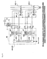
- Fig. 5 is a wiring diagram showing a wire connection between the first and second output circuits 205 and 206 in the basic module and the external electromagnetic contactor 10.
- the first output circuit 205 in the basic module 2 is constituted by tow transistors TR1 and TR2 complementarily connected each other and the second output circuit 206 is constituted by two transistors TR3 and TR4 complementarily connected each other.
- the connection point between the transistors TR1 and TR2 and that between the transistors TR3 and TR4 are taken out to external terminals T01 and T02.
- Coils MS1 and MS2 of magnet switches are connected between the external terminals T01 and T02 and a 0-V terminal respectively.
- the magnet switch MS1 has a triple-pole single-throw main-make contact MS1-1 and single-pole single-throw auxiliary break contact MS1-2.
- the magnet switch MS2 has a triple-pole single-throw main-make contact MS2-1 and a single-pole single-throw auxiliary break contact MS2-2. Then, these two main make contacts MS1-1 and MS2-1 are connected to a current-carrying route to a motor M which is the driving source of a dangerous source in series. Therefore, when both the first output circuit 205 and second output circuit 206 are turned on, the magnet switches MS1 and MS2 operate and the three-phase motor M is electrified by closing the main make contacts MS1-1 and MS2-1.
- Fig. 6 is a block diagram showing a hardware configuration of an input expansion module.
- the input expansion module 3 includes a first input circuit 301, second input circuit 302, third input circuit 303, fourth input circuit 304, first bus interface 305, and second bus interface 306.
- the first input circuit 301 has three external input terminals T11, T12, and T13 to be connected to the first terminal block (refer to Fig. 2) 31.
- the second input circuit 302 has three external input terminals T21, T22, and T23 to be connected to the second input terminal block (refer to Fig. 2) 32.
- the third input circuit 303 has three external input terminals T31, T32, and T33 to be connected to the third input terminal block (refer to Fig. 2) 33.
- the fourth input circuit 304 has three external input terminals T41, T42, and T43 to be connected to the fourth input terminal block (refer to Fig. 2) 34.
- a power terminal 24 V, GND
- a power terminal is connected to the mother board 53 through a power supply line 307.
- the first bus interface 305 and second bus interface 306 respectively include a nonvolatile memory and the memory stores the information for identifying the input expansion module 3 (module identifying information) and the like.
- the module identifying information (ID) is used to diagnose whether a predetermined expansion module is set to each expansion slot by collating the module identifying information read from the expansion slot 533-1 to N on the mother board 53 with the module identifying information set to the basic module.
- Fig. 7 is a block diagram showing a hardware configuration of an electromagnetic-relay output module serving as an output expansion module.
- the electromagnetic-relay output module 4A includes a first output circuit 401, second output circuit 402, monitor circuit 403, first bus interface 404, and second bus interface 405.
- the electromagnetic-relay output module 4A includes an electromagnetic relays K1 and K2.
- the electromagnetic relay K1 has two single-pole single-throw make contacts K1-1 and K1-2 and two single-pole single-throw break contacts K1-3 and K1-4.
- the electromagnetic relay K2 has two single-pole single-throw make contacts K2-1 and K2-2 and two single-pole single-throw break contacts K2-3 and K2-4. These contacts are set between external terminal strings T11, T21, and T31 on one hand and external terminal strings T12, T22, and T32 on the other in series or in parallel.
- Fig. 8 is a wiring diagram showing a wire connection between a relay contact in an electromagnetic-relay output module serving as an output expansion module and an external magnet switch.
- the same terminal as that in Fig. 7 is provided with the same symbol and its description is omitted.
- the electromagnetic relays K1 and K2 when both the electromagnetic relays K1 and K2 operate, coils of two magnet switches MS1 and MS2 are electrified, both the triple-pole single-throw main make contacts MS1-1 and MS2-1 are turned on, the three-phase motor M is electrified.
- Fig. 9 is a block diagram showing a hardware configuration of a solid-state-relay output module serving as an output expansion module.
- the solid-state-relay output module 4B includes a first output circuit 411, second output circuit 412, first monitor circuit 403a, second monitor circuit 403b, first bus interface 404, and second bus interface 405.
- the first output circuit 411 is connected to external terminals T13 and T14.
- the second output circuit 412 is connected to external terminals T23 and T24.
- the first monitor circuit 403a is connected to an external terminal T11 and the second monitor circuit 403b is connected to an external terminal T21. External terminals T12 and T22 are connected to a power supply coming from the mother board 53.
- Fig. 10 is a wiring diagram showing a wire connection between a relay in a solid-state-relay output module and an external electromagnetic contactor.
- the solid-state-relay output module 4B includes a first solid-state relay 411a, second solid-state relay 412b, first monitor circuit 403a, second monitor circuit 403b, first and second bus interfaces 404 and 405, and fuses 406 and 407.
- the magnet switches MS1 and MS2 are electrified and the three-phase motor M is electrified when the main make contacts MS1-1 and MS2-1 are turned on.
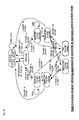
- Fig. 11 is an illustration showing a hardware configuration of a mother board.
- the mother board 53 is set in the module holder 5 of the safety controller 1 and has the basic module connector 531, two address decoders 532a and 532b, and n expansion-module connectors 533-1 and 533-2 to 533-n.
- a data line 534 and address lines 535a and 535b of two systems are derived from the basic-module connector 531.
- the address line 535a is decoded by the address decoder 532a and thereby, a slot select line 536a is derived.
- the address line 535b is decoded by the address decoder 532b and thereby, a slot select line 536b is generated.
- the basic module 2 is removably set to the basic-module connector 531.
- various expansion modules (such as input expansion module 3 and output expansion module 4) are removably set to the expansion-module connectors 533-1 to 533-n.
- n expansion-module connectors 533-1 to 533-n are drawn as first slot, second slot,..., and n-th slot.
- specific configurations shown in Fig. 2 are purposed, it is not needless to say that only two expansion-module connects are necessary.
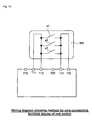
- Fig. 12 is a wiring diagram showing a method for wire-connecting terminal blocks of an emergency stop switch.
- an emergency stop switch ES includes one pushbutton PB0 and two break contacts b0-1 (first system) and b0-2 (second system) to be operated while interlocking with operations of the pushbutton PB0.
- the first break contact b0-1 is connected between the external terminals T11 and T12 and the second break contact b0-2 is connected between the external terminals T21 and T22.
- Fig. 13 is a wiring diagram showing a method for wire-connecting terminal blocks of both operation switches. Also in the case of this example, six external terminals T13, T11, T12, T23, T21, and T22 are arranged in order on external terminal blocks for one safety switch. Moreover, a two-hand-control switch 2HS is provided with two pushbuttons PB1 and PB2, a pair of break and make contacts b1-1 and a1-2 of a first system to be operated while interlocking with operations of the pushbutton PB1, and a pair of break and make contacts b2-1 and a2-2 of a second system to be operated while interlocking with operations of the pushbutton PB2.
- break contact b1-1 is connected between the external terminals T13 and T11 and the make contact a1-2 is connected between the external terminals T11 and T12. Furthermore, the break contact b2-1 is connected between the external terminals T23 and T21 and the make contact a2-2 is connected between the external terminals T21 and T22.
- Fig. 14 is a wiring diagram showing a method for wire-connecting terminal blocks of a mat switch. Also in the case of this example, six external input terminals T13, T11, T12, T23, T21, and T22 are arranged in order on external terminal blocks corresponding to one safety switch.
- the mat switch MS includes a plurality of make contacts a1, a2, and a3 which are parallel each other. Moreover, a common line at one end (first system) of a group of these make contacts is connected between the terminals T11 and T12 and moreover, another common line (second system) of a group of make contacts is connected between the terminals T21 and T22.
- Fig. 15 is a wiring diagram showing a method for wire-connecting terminal blocks of a safety limit switch.
- a safety limit switch SLS includes a pair of make contact a1 and a break contact b1 to be operated while interlocking with operations of a safety guard serving as an actuator of the limit switch.
- the make contact (first system) a1 is connected between the terminals T11 and T12.
- the break contact (second system) b1 is connected between the terminals T21 and T22.
- Fig. 16 is a wiring diagram showing a method for wire-connecting terminal blocks of a light curtain.
- two power supply terminals 24 V, GND
- six eternal input terminals T13, T11, T12, T23, T21, and T22 are arranged in order on external terminal blocks corresponding to one safety switch.
- a reset signal corresponds to the terminal T11 which is the first system
- a control output 1 corresponds to T12
- a test signal (TEST) corresponds to T21 which is the second system
- a control output 2 corresponds to the terminal T22.
- a porous-axis light curtain LC if formed between a projector T and a light sensor R to generate the control outputs 1 and 2 when a human body contacts the curtain.
- Fig. 17 is a wiring diagram showing a method for wire-connecting an electromagnetically-locking safety door switch and a safety limit switch.
- solenoid driving terminals (A, B) and six external input terminals T13, T11, T12, T23, T21, and T22 are arranged in order on external terminal blocks for one safety switch.
- a safety limit switch SLS is provided with one break contact b1 to be driven by a slide actuator (safety guard) and an electromagnetically-locking safety door switch MDS includes a break contact b1 (for confirming solenoid operations) to be operated while interlocking with operations of a solenoid SOL and two break contacts b2 and b3 (inoperative) to be operated while interlocking with the haunting operation of a removal-preventive lock pin p.
- two break contacts b1 and b2 serving as the first system are connected between the terminals T11 and T12.
- the break contact b1 of the safety limit switch SLS is connected between the terminals 21 and 22.
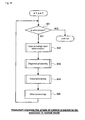
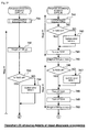
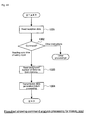
- Fig. 18 is a flowchart schematically showing the whole of a control program to be executed by first and second CPUs. Execution of the flowchart is started by turning on power.
- Fig. 18 when the first processing is started, initialization of an internal RAM and various initializations are executed (step 101).
- the internal RAM in this case denotes a RAM or the like constituting work areas in the first CPU 201 and second CPU 202.
- steps 102 various diagnostic processings for improving the reliability of a safety system are executed as to be described later in detail.
- step 103 it is determined whether a predetermined command generated by operating the personal computer (PC) 6 reaches the basic module 2. In this case, it is determined that the command for set-mode irruption is present (YES in step 103), the processing of a set mode (step 104) is executed. However, when the set-mode-irruption command does not reach the basic module 2 (NO in step 103), the processing of the normal mode (step 105) is executed.
- Fig. 19 is a flowchart showing the whole of a control program to be executed in a set mode.
- processings in various set modes are executed (step 204) while checking whether a command is received (NO in step 201).
- Other processings (step 204) in this case will be described later according to necessity.
- step 201 When it is confirmed that the command is received (YES in step 201), the command is analyzed and data is written (step 202) in EEPROMs 202a and 202b (refer to Fig. 4). When write of the data is completed, the response processing (step 203) is executed and a response showing normal end or abnormal end of write is returned to the personal computer (PC) 6 through the communication circuit (RS-232C) 207.
- PC personal computer
- RS-232C communication circuit
- Fig. 20 is a flowchart showing details of the command analysis and EEPROM write processing.
- received data is read (step 301) and it is determined whether the content of a read command is an EEPROM write command (step 302).
- the processing is shifted to the other-command processing.
- the specified address of the data to be written in the EEPROM is determined (step 303). In this case, the specified address is determined as 00 to 3F (hex), the reception data is address-designated to the memory area concerned of the basic module and written in the EEPROM of the area concerned (step 306).
- the reception data is address-designated to the memory area concerned of an expansion module (step 305) and the data is written in the both EEPROMs 209a and 209b (refer to Fig. 4) (step 306).
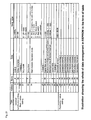
- Fig. 21 is an illustration showing the whole of the data arrangement in the EEPROMs 209a and 209b in the form of a table. As shown in Fig. 21, a memory area relating to common specification setting and basic module setting and a memory area relating to expansion module setting are formed in the address space in an EEPROM.
- CRC (0-FFFFh) as two bytes from address 0, delay time table (0-300) as 30 bytes from address 2, spare space (reserve) as one bye from address 20, delay mode (0: off-delay, 1: on-delay) as one byte from address 21, delay time (0-300) as two bytes from address 22, main module: operation mode as one byte from address 24: (0: 2N, C: emergency stop switch or the like, 1: 1N, C+1N, 0, 2: two-hand switch, 3: mat switch, 4: light curtain), spare space (reserve) as one byte from address 25, digital filter value (1-255) as 30 bytes from address 26, allowance of time difference between safety input systems (0: infinite, 1-255) as one byte from address 30, manual reset-on maximum time (0: infinite, 1-255) as one byte from address 31, format data as eight bytes from address 32, spare space (reserve) as two bytes from address 3A, and hardware version (0,00-99
- Data values corresponding to connection modules 1 to 8 are stored in areas for setting expansion modules as 16 bytes respectively from addresses 40, 50, 60, 70, 80, 90, A0, and B0.
- Fig. 22 is an illustration showing the data arrangement for expansion input modules in an EEPROM in the form of a table. As shown in Fig. 22, the following are stored in memory areas assigned to expansion input modules:
- Fig. 23 is an illustration showing the data arrangement for expansion output modules in an EEPROM in the form of a table. As shown in Fig. 23, the following are stored in memory areas for expansion output modules:
- the delay mode and delay time are used to allow each expansion output module to generate on-delay output or off-delay output and the delay time can be freely set in a range of 0 to 300 ( ⁇ 100) msec. It is a matter of course that the processing for realizing a corresponding output function by referring to contents and delay times of those delay modes are built in the operation program for expansion output modules correspondingly to the table.
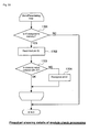
- Fig. 24 is a flowchart showing the whole of a control program to be executed in the normal mode.
- input processing/output determination processing step 402
- diagnosis processing step 403
- output processing step 404
- other processings step 405
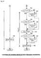
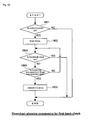
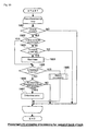
- Fig. 25 is a flowchart (1) showing details of the output determination processing and Fig. 26 is a flowchart (2) showing details of the output determination processing.
- step 502 it is determined whether the designated slot is an input module. In this case, when it is determined that the slot is an input module (YES in step 502), reading a safety input value is executed (step 503). Then, the operation mode requested to the module set to the slot is determined and any one of the output determination processings (steps 505, 506, 507,...) of the switch concerned is executed in accordance with the fact that the operation mode is "emergency stop switch", "two-hand-control switch", or "mat switch". In these determination processings, the present on/off state of the safety switch concerned is determined by executing a predetermined safety operation program correspondingly to the type and internal structure of each safety switch. The on or off state thus determined is stored in a memory (step 508).
- step 510 it is determined whether all safety inputs are on in Fig. 26 (step 510).
- step 512 when it is determined that all the safety inputs are on (YES in step 510), it is determined that the outputs are turned on (step 511). Thereafter, presence or absence of a reset input is determined (step 512).
- step 512 the start processing of an on-delay timer is executed (step 514) by premising that the on-delay timer is not started yet (NO in step 513) and it is determined that outputs are off (step 517) until the on-delay timer counts up (NO in step 515).
- step 515 when counting-up by the on-delay timer is confirmed (YES in step 515), it is determined that outputs are on. Thereby, an on-delay function for external outputs is realized.
- no reset input NO in step 512
- it is immediately determined that outputs are off step 517).
- Presence or absence of the reset input determined in step 512 is based on a signal sent from a reset button connected to the first input circuit 203 or second input circuit 204 of the basic module. That is, in the case of this type of safety system, a small pushbutton to be lightly operated by a finger tip is set to perform the reset operation of the whole system to reset the start of the whole system by operating the pushbutton in general.
- step 519 when it is determined that any one of inputs is off (NO in step 510), outputs are determined to be off (step 518) and then, it is determined whether outputs are on in the last determination (step 519).
- the start processing of an off-delay timer is executed (step 521) by premising that the off-delay timer is not started yet (NO in step 520) and it is determined that outputs are on until counting-up by the off-delay timer is confirmed (NO in step 522).
- step 523 when counting-up by the off-delay timer is confirmed during the above operations (YES in step 522), it is determined that outputs are off (step 523). Thereby, the off-delay function for external outputs is realized.
- it is determined in the last determination that outputs are not on NO in step 519
- it is immediately determined that outputs are off step 523).
- on-delay processing is automatically executed when all safety inputs are on and off-delay processing is executed when all safety inputs are off. These processings are executed when allocating one output to a plurality of safety input switches.
- a safety controller of the present invention it is also possible to relate a plurality of expansion output modules to a plurality of safety switches.
- the data arrangement for an expansion output module shown in Fig. 23 previously described is prepared by assuming the above case. That is, as previously described, a delay mode and delay time can be set for each expansion output module.
- steps 511 to 517) and the off-delay processing steps 518 to 5234 described in Fig. 26 is executed for an expansion output mode to which the delay mode is set.
- the on-delay processing or off-delay processing is executed for each of a plurality of expansion output modules.
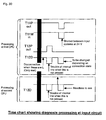
- Fig. 27 is a flowchart showing details of the diagnosis processing. As shown in Fig. 27, in this processing, when an error code is determined (YES in step 603) in either of the input diagnosis processing (step 601) and other diagnosis processing (step 602) while executing the both processings, the processing for storing the error code in a memory is executed (step 604).
- the input diagnosis processing has two large functions.
- the first function is to diagnose a safety switch externally connected to an input terminal block.
- the second function is to diagnose states of an output circuit and input circuit present in an input terminal block.
- the output circuit denotes a drive circuit for selectively supplying a voltage to each terminal constituting the input terminal block and the input circuit denotes a level sift circuit for lowering 24 V supplied to the terminal block form an external unit to 5 V for an logic IC and a gate set to the rear stage of the level shift circuit.
- the contact configuration of a safety switch includes a no-voltage contact and a voltage contact.
- An emergency stop switch, mat switch, and two-hand-control switch mainly correspond to the no-voltage contact.
- a light curtain or the like corresponds to the voltage contact.
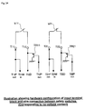
- Fig. 34 is an illustration sowing a wire connection between a hardware configuration and a safety switch of an input terminal block (corresponding to no-voltage contact)
- Fig. 35 is an illustration showing a wire connection between a hardware configuration and a safety switch of an input terminal block (corresponding to voltage contact).
- the input terminal block is provided with four terminals of T11, T12, T21, and T22.
- the break contact b11 of the first system of a safety switch is connected between the terminals T11 and T12.
- the break contact b21 of the second system is connected between the terminals T21 and T22.
- An input circuit and output circuit set in this terminal block are constituted as described below.
- An output circuit and input circuit are connected to the terminal block in anti-parallel though they are not illustrated in terminal T11.
- a signal output from the output circuit is expressed as T11P (out) and a signal input to the input circuit from the terminal T11 is expressed as T11M (in).
- An input circuit and output circuit are also set to the terminal T12 though they are not illustrated.
- a signal input to an input circuit from the terminal T12 is expressed as T12D and a signal output from an output circuit to drive a transistor TR11 is expressed as T12P (out).
- the terminal T21 is provided with an output circuit and input circuit in anti-parallel though they are not illustrated.
- a signal output to the terminal T21 from the output circuit is expressed as T21P (out) and a signal input to the input circuit from the terminal T21 is expressed as T21M (in).
- an input circuit and output circuit are also set to the terminal T22.
- a signal input to the input circuit from the terminal T22 is expressed as T22D and a signal output from the output circuit to drive a transistor TR21 is expressed as T22P (out).
- the contact b11 of the first system of a safety switch is connected between the terminals T11 and T12.
- the break contact b21 of the second system is connected between the terminals T21 and T22.
- the break contact b11 of the first system is connected between the power supply 24 V and the terminal T12.
- the break contact b21 of the second system is connected between the power supply 24V and the terminal T22.
- diagnosis processings are processings of properly supplying output signals to the terminals T11, T12, T21, and T22 previously explained, functions are previously fixed about outputting voltages to these terminals. That is, it is assumed that outputting voltages to the terminals T11 and T12 of the first system is perform by the first CPU and outputting voltages to the terminals T21 and T22 of the second system is performed by the second CPU.
- These relations are fixed in hardware.
- signals can be received from those four terminals T11, T12, T21, and T22 by the first CPU and second CPU in parallel. That is, signals can be received from these four terminals T11, T12, T21, and T22 by both the first CPU and second CPU.
- Figs. 28 and 29 When the first processings are started, the first CPU and second CPU first establish synchronization by executing communication between the CPUs each other (steps 701 and 721) .
- the first CPU determines whether T12D is on (step 702). As shown by the circuit in Fig. 34, it is possible to determine whether the break contact b11 of the first system is disconnected or it is not electrified by confirming whether the T12D is on ("H") or off ("L") when the T11P (out) is on ("H"). In this case, it is determined that the T12D is not on (NO in step 702), an error table 4 (described later) is updated (step 703) and occurrence of the disconnection or not-electrification is stored. However, when T12D is on ("H") (YES in step 702), it is determined that the disconnection or not-electrification does not occur.
- the first CPU turns on T12P ("H") (step 704) and executes the weight processing of 100 ⁇ s or more (step 705) and then, determines whether T12D is off ("L") (step 706).
- determining whether T12D is off ("L") while turning on T12P ("H") represents to diagnose the state of the input circuit connected to the terminal T12.
- a predetermined error table 1 is updated (step 707) and the trouble of the input circuit built in the terminal T12 at the first system is stored.
- the first CPU turns off T12P ("L") (step 708) and turns off T11P ("L”) (step 709), executes the weight processing of 300 ⁇ s or more (step 710), then in Fig. 29, determines whether T11min is off ("L") (step 711). In this case, determining whether T11min is off ("L") while turning off T12 ("L") and turning off T11P ("L") represents to determine whether a short circuit occurs between the break contact b11 of the first system and the break contact b21 of the second system. In this case, when it is determined that T11min is not off (“L") (NO in step 711), an error table 3 is updated (step 712) and the above described short circuit between the first system and the second system is stored.
- the first CPU executes to determine whether T12D is off ("L") (step 713).
- determining whether T12D is off (“L") represents a case in which wiring of 24 V to a mat switch is erroneously connected or disconnected particularly when a safety switch is the mat switch.
- an error table 6 is updated (step 714) and the fact that an abnormal wiring is applied to the mat switch is substantially stored.
- the first CPU turns on T11P ("H") and determines whether T11M is on (“H") (step 716). In this case, determining whether T11M is on ("H") while turning on T11P ("H") represents that a circuit built in the terminal T11 of the first system is troubleshot. In this case, when it is determined that T11M is not on ("H") (NO in step 716), an error table 5 is updated (step 717) and a trouble of the circuit built in the terminal T11 is stored.
- the second CPU performs the communication between the CPUs (step 721), executes the weight processing of 100 ⁇ s (step 722), then determines whether T12D is off ("L") (step 723).
- T12D is off
- the fact that T12D is off ("L") is the same as the processings (in steps 706 and 707) previously executed at the first CPU. This represents that the second CPU also determines whether the internal input circuit in the T12 is normal.
- stages #1, #2, and #3 are successively executed at the first CPU and finally, the both CPUs execute determination processings (in steps 718 and 725) when the state of the stage #1 is completed at the second CPU.
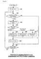
- Fig. 36 is a flowchart showing details of determination processing.
- This determination processing determines a trouble of a safety switch and/or troubles of the input and output circuits built in an input terminal block by referring to the contents of the error table shown in Fig. 37. That is, as shown in Fig. 37, a diagnosis result storage area is provided for the basic module and each of the expansion modules 1 to 8 in the input-diagnosis table. Moreover, in Fig. 37, the area in which "mode" is written shows operation modes of the modules.
- the upper side denotes processings by the first CPU and the lower side denotes the processing by the second CPU.
- the processing by the first CPU makes it possible to determine a trouble state of an internal circuit by referring to the signal state of T12D while turning on T2P (out) ("H").
- the processing makes it possible to determine a trouble state of the internal circuit as a short circuit between input systems by referring to the state of T11M (in) while turning off T11P (out) ("L").
- the processing makes it possible to determine a trouble state of the internal circuit as disconnection only in the case of a mat switch when the signal state of T12D is kept at "L" from the beginning as a result of referring to it. Moreover, in the case of the processing by the second CPU, it is possible to properly determine a trouble state of the internal circuit by referring to T12D.
- FIG. 31 to 33 second-half processings of the input diagnosis processing are described below by referring to Figs. 31 to 33.
- These processings correspond to the previously-described first-half processings in which the first CPU and second CPU are replaced each other. That is, in the case of this embodiment, it is possible to securely detect a short circuit between two systems of connected safety switches by alternately executing the same processing by the first CPU and second CPU and thereby providing a time difference between troubleshooting periods.
- the processings in Figs. 31 to 33 are completely the same as those in Figs. 28 to 30. Therefore, detailed description is omitted.
- Fig. 36 is a flowchart showing details of determination processing.
- table-1 error ⁇ 2 is first determined (step 801).
- an error code is set (step 802).
- table-2 error ⁇ 2 is determined (step 803). In this case, only when not table-2 error ⁇ 2 is determined (NO in step 803), an error code is set (step 804).
- table-5 error ⁇ 2 is determined (step 805). In this case, only when not table-5 error ⁇ 2 is determined (NO in step 805), an error code is set (step 806).
- step 807 it is determined whether the operation mode is a mat mode. In this case, when it is determined that the operation mode is not a mat mode (YES in step 807), table-3 error ⁇ 2 is determined (step 808). In this case, only when not table-3 error ⁇ 2 is determined (NO in step 808), an error code is set (step 809).
- step 810 when the operation mode is determined as a mat mode (NO in step 807), table-4 error ⁇ 2 is determined (step 810). In this case, only when not table-4 error ⁇ 2 is determined (NO in step 810), an error code is set (step 813).
- table-6 error ⁇ 2 is determined (step 811). In this case, only when not table-6 error ⁇ 2 is determined (NO in step 811), an error code is set (step 812).
- the safety controller stops operations and is shifted to the so-called lock-out state. That is, when a safety switch connected to an external unit is disconnected or short-circuited or an input circuit output circuit built in an input terminal block has a trouble, operations of the safety controller are immediately stopped and shift to a dangerous state due to these troubles is prevented.
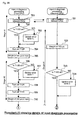
- Fig. 38 is a flowchart showing details of the output processing executed by a basic module or an expansion module.
- a pointer for designating a slot is initialized to "+1"(step 901) and then, it is determined whether the module (basic module or expansion module) set to the slot designated by the pointer is an output module (step 902).
- step 902 when it is determined that the module is an output module (YES in step 902), output determination values stored in steps 516, 517, 523, and 524 in the flowchart in Fig. 26 are read (step 903) and output processings corresponding to the determination values are executed (step 904).
- a corresponding slot is an output module while updating the value of a pointer designated by a slot +1 by +1.
- an output signal is transmitted to an external unit from a corresponding output terminal block of a basic module or expansion module by repeating the above processings (steps 903 and 904).
- a safety controller of the present invention stores a safety operation program for defining the relation between the state of a safety input signal and the state of a safety output signal in the program memories 202a and 202b in the basic memory 2 for each type of predetermined safety switches while setting an external input terminal section and the type of safety switches to be connected to the external terminal section through the personal computer (PC) 6. Thereafter, the controller selects a safety operation program corresponding to the switch type set by setting part among a plurality of safety operation programs stored in the program memories 202a and 202b serving as operation program storing part in the operation mode and executes the selected program for the external input terminal section set by the setting part. Therefore, it is possible to connect an optional type of safety switches to a basic and an expansion module and efficiently realize a desired safety system by properly executing operation programs corresponding to the safety switches and thereby variously combining an optional number of safety switches.
- each input terminal block not only externally-connected safety switches but also internal input and output circuits are properly troubleshot. Therefore, it is possible to operate a safety controller while maintaining a high safety together with the processing of them.
- Fig. 39 is a state transition diagram showing operations of a controller (input determining section) in an emergency stop switch.
- the state transition diagram includes seven states such as "INITIAL”, “READY#2", “TIMEOUT#2”, “ON”, “TIMEOUT#3", “TIMEOUT#1", and "READY#1". The transition between these states is performed when specific conditions are effected. In Fig. 39, these conditions are respectively expressed by an arrow and a symbol attached to the arrow.
- How to read the state transition diagram is easily understood by a person skilled in the art in accordance with the above procedure. However, main operations are understandably described below for confirmation by using a flowchart.
- Fig. 40 is a flowchart showing a processing program for determining that an emergency stop switch is changed from off to on.
- the terminals T12 and T13 (refer to Figs. 34 and 35) are off ("L") (step 1001).
- step 1002 it is determined whether T12 is on ("H"). In this case, when it is determined that T12 is not on ("H") (NO in step 1002), step 1009 is started and it is determined that the emergency stop switch is off.
- a inter-system sync monitoring timer is started (step 1004) to determine whether T22 is on ("H") (step 1005) by premising that the inter-system-sync monitoring timer is not currently started (NO in step 1003). In this case, when T22 is not on ("H") (NO in step 1005), it is waited for the inter-system-sync monitoring timer to expire (step 1008).
- the history processing to be described later step 1006 is executed and then it is determined that the emergency stop switch is on (step 1007).
- the inter-system-sync monitoring timer expires (YES in step 1008), it is determined that the emergency stop switch is off (step 1009).
- Fig. 41 is a flowchart showing a processing program for determining that the emergency stop switch is changed from on to off.
- the terminals T12 and T22 are on ("H") (step 1101).
- T12 is on ("H") (YES in step 1102) and T22 is also on (“H") (YES in step 1103), it is determined that the emergency stop switch is on.
- T12 and T22 is off ("L") (NO in step 1102 or 1103)
- the emergency stop switch is off (step 1105).
- step 1006 the history processing is executed in step 1006 while a safety switch operates.
- the history processing (step 1006) measures the sync shift time between input timings on input signals T12 and T22 of two systems of a safety switch and stores the time in a memory in time series.
- the sync shift time T1 shown in Fig. 43B is stored in an address designated by a pointer in a memory area constituting an FIFO stack while making the pointer step +1 by +1 (step 1201).
- contents of the pointer are cleared to 0 (step 1203) when the value of the pointer exceeds the final address (YES in step 1202).
- the previously-described sync shift times (T1) are successively stored in the history generation area (refer to Fig. 43A) formed in the work area of a RAM of the basic module 2 as the measured times between safety input systems as shown in Fig 43A. That is, in the case of the example in Fig. 43A, the sync shift times (T1) are stored in the area of addresses 0001, 0002, 0003, 0004,..., and 000F designated by the pointer as 95 ms, 100 ms, 102 ms, 100 ms,..., and 98 ms.
- the time chart in Fig. 43B shows the comparison between on-timings of input terminals T12 and T22 of two systems of a safety switch.
- sync shift times Differences between rise times of the on-timings serves as the sync shift times (T1). These sync shift times (T1) are compared with a monitoring threshold value (Th). When any one of the sync shift times (T1) exceeds the monitoring threshold value (Th), it is determined that the emergency stop switch is off (step 1009) because of the expiry of the timer as shown by step 1008 in the previous flowchart.
- a basic module reads reception data (step 1301) and when it is determined that a read command is a safety-input sync time read command (step 1302), memory contents are read by the number of designated histories (step 1303), and transmission data is generated in accordance with the memory contents and transmitted to the personal computer (PC) 6 outputting a read request (step 1304).
- the safety controller detects the rise time differences (sync shift times T1) between input signals of the first and second systems constituting an input switch while performing normal operations as shown in Fig. 40 and stores the differences in the history generation area in time series as shown in Fig. 43A, then transmits a predetermined read command from the personal computer (PC) 6 at the point of any time.
- the safety controller reads data from the history generation area, generates transmission data, and transmits the data to the personal computer (PC) 6.
- the personal computer (PC) 6 can be used for various purposes such as comparing a series of sync shift times (T1) read from the basic module with a proper threshold value, graphing the degree of the time-series change and thereby, determining the contact deterioration state of a safety switch to be handled, and estimating the remaining time up to seizure.
- T1 sync shift times
- Fig. 45 is a state transition diagram showing operations (input determining section) of a controller in the two-hand-control-switch mode.
- the state transition diagram includes 8 states such as "INITIAL#1", “INITIAL#2", “READY#1", “TIMEOUT#1”, “TIMEOUT#3”, “ON”, “TMIEOUT#2”, and "READY#2".
- shift conditions between these states are respectively expressed by an arrow and a symbol attached to the arrow as previously explained.
- a person skilled in the art will be able to easily understand the state transition diagram in accordance with the previous procedure. However, typical operations are understandably explained below for confirmation by referring to Figs. 46 to 48.
- step 1401 when the fist processing is started, it is waited for the terminals T12 and T22 to be off ("L") and the terminals T13 and T23 to be on ("H") (step 1401). Under the above state, when the terminals T12 and T22 become off ("L") and the terminals T13 and T23 become on (“H") (YES in step 1401), it is determined whether the terminal T12 is on ("H") (step 1402). In this case, when it is determined that the terminal T12 is also on (“H") (YES in step 1402), the inter-contact monitoring time is started (step 1404) and then it is determined whether the terminal T13 is off ("L") by premising that the inter-contact sync monitoring timer is not currently started (NO in step 1403).
- step 1405 it is determined whether the terminal T22 is on ("H") and the terminal T23 is off (“L") (step 1408). In this case, when it is determined that the terminal T22 is on ("H") and the terminal T23 is off (“L") (YES in step 1408), it is determined that the two-hand-control switch is on (step 1409).
- step 1406 when the inter-contact sync monitoring timer expires (YES in step 1406) while it is waited for the terminal T13 to be off ("L") (NO in step 1405), it is determined that the two-hand-control switch is off (step 1407) and the processing is completed. Moreover, unless the terminal T22 is on ("H") and T23 is off ("L") (NO in step 1408), the inter-system sync monitoring timer is started (step 1411) and then it is waited for the inter-system sync monitoring time to expire (NO in step 1412) by premising that the inter-system sync monitoring timer is not currently started (NO in step 1410). Under the above state, when the inter-system sync monitoring timer expires (YES in step 1412), it is determined that the two-hand-control switch is off (step 1413).
- Fig. 48 is a flowchart for showing a processing program for determining that the two-hand-control switch is changed from on to off.
- the terminals T12 and T22 are on ("H") and the terminals T13 and T23 are off ("L") (step 1501).
- T12 is on (YES in step 1502)
- T22 is on (YES in step 1503)
- T13 is off (YES in step 1504)
- T23 is off (YES in step 1505)
- it is determined that the two-hand-control switch is on (step 1506).
- any one of the facts is determined that T12 is not on (NO in step 1502), T22 is not on (NO in step 1503), T13 is not off (NO in step 1504), and T23 is not off (NO in step 1505), it is determined that the two-hand-control switch is off (step 1507).
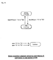
- Fig. 49 is a state transition diagram showing operations (input determining section) of a controller of a mat switch.
- the state transition diagram includes two states such as "INITIAL” and "ON". The shift between these states is performed in the case of mat-on or mat-off. Therefore, this is very simple.
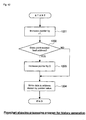
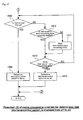
- Fig. 51 is a flowchart showing details of module check processing.
- the module check processing makes it possible to self-diagnose the determination on whether an optional expansion slot set to an expansion slot on a mother board is a preset type of expansion module.
- the module check processing is executed in, for example, the other diagnosis processing (step 602) shown in Fig. 27.
- Fig. 51 when the first processing is started, it is determined whether an ID is assigned to a memory corresponding to the slot (step 1701). In this case, when the ID is assigned to the memory (YES in step 1701), the ID is read from an actual module (step 1702) and then, the ID stored in the memory is collated with the ID read from the module (step 1703), an error is recognized when the both IDs are mismatched (step 1704), and start of a controller is inhibited. Because the above processing is applied to every slot set to a mother board, a malfunction is prevented by executing the module check processing when a different type of expansion module is set to designated slot due to an error of an operator though various types of expansion modules are set to slots from a personal computer.
- Fig. 52 is a wiring diagram showing a wire connection method for first back check and Fig. 53 is a flowchart showing the processing for the back check.
- a feedback terminal FB0 is set to the basic module 2.
- the auxiliary break contact MS1-2 and of the magnet switch MS1 and auxiliary break contact MS2-2 of the magnet switch MS2 are set in series between the FB0 and the power supply 24 V. Therefore, by observing the voltage ("H" or "L") of the feedback terminal FB0, it is possible to confirm whether the main make contacts MS1-1 and MS2-1 of the magnet switches MS1 and MS2 are actually turned off after transmitting a safety output signal to the magnet switches. That is, as shown in Fig.
- step 1804 when a monitoring time exceeds a set value (YES in step 1804) while a feedback input is kept on (step 1803) after a timer is started (step 1802), it is possible to immediately detect a contact seizure trouble of the main contact of MS1-1 or that of MS2-1 of the magnet switches MS1 and MS2 by determining the fact that the monitoring time exceeds the set value as an error.
- Fig. 54 is a wiring diagram showing a wire connection method for second back check
- Fig. 55 is a flowchart (1) showing the processing for the second back check
- Fig. 56 is a flowchart (2) showing the processing for the second back check.
- two feedback terminals FB1 and FB2 are set to an expansion unit 4A'.
- the auxiliary break contacts MS1-2 and MS2-2 of the magnet switches MS1 and MS2 are connected each other through a power supply.
- Contents of the history generation area shown in Fig. 57A can be properly read to the personal computer (PC) 6. That is, as shown by the flowchart in Fig. 56B, when reading reception data from the basic module (step 2101) and it is determined that a read command is a feedback-time read command (step 2102), contents of the memory are read by the specified number of histories (step 2103), and transmission data is generated in accordance with the read contents and transmitted to the personal computer (PC) 6 outputting a read request (step 2104).
- Fig. 55 by detecting the time difference in which a feedback input is turned on while a predetermined monitoring time elapses, storing the time difference in the history generation area in time series as sown in Fig. 57A, and then transmitting a predetermined read command from the personal computer (PC) 6 at any point of time, data is read from the history generation area and transmission data is generated and transmitted to the personal computer (PC) 6 as shown by the flowchart in Fig. 56B.
- the personal computer (PC) 6 can be used for various purposes such as comparing a series of feedback times read from the basic module with a proper threshold value, determining the contact deterioration sate of a magnet switch to be handled by graphing the degree of the time-series change of the feedback times, and estimating the remaining time up to seizure.
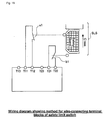
- Fig. 58 is an illustration (1) of a safety controller having an operation-state monitoring terminal.
- a safety controller having an operation-state monitoring terminal.
- PLC programmable controller
- SC safety switch
- contactors KM2 and KM3 are prevented from being carelessly operated by the safety controller (SC) because the safety switch operates whenever a worker enters a dangerous area when maintenance or operation is stopped by not outputting a cutoff output OUT2 or OUT3 in accordance with a signal sent from the safety switch even if a dangerous state is determined.
- control system of the apparatus is controlled by the programmable controller (PLC) and a person management system is independently executed b the safety controller (SC).
- PLC programmable controller
- SC safety controller
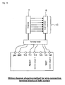
- Figs. 59A and 59B show illustrations (2) of a safety controller having an operation-state monitoring terminal.
- magnet switches KM1, KM2, and KM3 are used for the control system and person management system of a conventional apparatus respectively and the switch KM1 is turned on/off by a programmable controller (PLC) and the switches KM2 and KM3 are turned on/off in accordance with outputs OUT2 and OUT3 of a safety controller (SC).
- PLC programmable controller
- SC safety controller
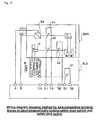
- Figs. 60A and 60B show illustrations of solenoid cutoff using an input circuit.
- This diagnosis processing can be performed at a proper timing, for example, immediately after power is turned on or during the diagnosis processing in the normal mode.
- Fig. 61 shows an output control mode (1) of an operation program corresponding to each safety switch and Fig. 62 shows an output control mode (2) of the operation program.
- Fig. 61A shows a mode of simultaneously turning off outputs of all output sections (OUTmain) of basic modules or outputs (OUT1 and OUT2) of all expansion output modules when it is determined that a safety switch is off in any one of input sections (INmain) of basic modules and two expansion modules (INadditional 1 and 2) under the control of the basic module (main).
- the configuration shown in Fig. 61B instantaneously turns off the output section (OUTmain) of a basic module and the output section (OUT1) of a first expansion module and makes the output section (OUT2) of a second expansion module to execute off-ready output when it is determined that a safety switch is off in any one of the input section (INmain) of a basic module and two expansion input modules (INadditional 1 and 2) under the control of the basic module (main).
- Fig. 62A instantaneously turns off the output section (INmain) of a basic module when the input section (OUTmain) of a basic module determines that a safety switch is off under the control of the basic module (main) while instantaneously turning off output sections (OUT1 and OUT2) of expansion modules when it is determined that a safety switch is off in either of input sections (INadditional 1 and 2) of two expansion modules.
- the configuration shown in Fig. 62B instantaneously turns off the output section (OUTmain) of a basic module and output sections (OUT1 and OUT2) of two expansion modules when the input section (INmain) of a basic module determines that a safety switch is off under the control of the basic module (main) and instantaneously turns off output sections (OUT1 and OUT2) of two expansion modules when either of input sections (INadditional 1 and 2) of two expansion modules determines that a safety switch is off.
- the safety operation program described above is fixedly built in when it is shipped from a factory, it cannot be changed or operated by a user. Therefore, by previously obtaining the approval of the safety standard also for export for Europe, even if a user performs setting corresponding to any safety switch, it is not necessary to obtain the approval of the safety standard each time after constructing a system.
- the present invention makes it possible to easily set a necessary operation program to any type of safety switch as long as the safety switch is one of a plurality of types of predetermined safety switches and moreover, it is not necessary to obtain the approval of the safety standard whenever building the program in a safety system even in the case of export to Europe or the like. Furthermore, according to the present invention, it is possible to construct a safety system including many safety switches or increase the number of safety switches in an existing safety system at a low cost in addition to the above mentioned.
Landscapes
- Physics & Mathematics (AREA)
- General Physics & Mathematics (AREA)
- Engineering & Computer Science (AREA)
- Automation & Control Theory (AREA)
- Programmable Controllers (AREA)
- Safety Devices In Control Systems (AREA)
Applications Claiming Priority (4)
| Application Number | Priority Date | Filing Date | Title |
|---|---|---|---|
| JP2003076578 | 2003-02-12 | ||
| JP2003076578 | 2003-02-12 | ||
| JP2003068942 | 2003-03-13 | ||
| JP2003068942 | 2003-03-13 |
Publications (3)
| Publication Number | Publication Date |
|---|---|
| EP1460497A2 true EP1460497A2 (de) | 2004-09-22 |
| EP1460497A3 EP1460497A3 (de) | 2005-09-28 |
| EP1460497B1 EP1460497B1 (de) | 2012-11-14 |
Family
ID=32828999
Family Applications (1)
| Application Number | Title | Priority Date | Filing Date |
|---|---|---|---|
| EP04002817A Revoked EP1460497B1 (de) | 2003-02-12 | 2004-02-09 | Sicherheitssteuerung |
Country Status (3)
| Country | Link |
|---|---|
| US (1) | US7242116B2 (de) |
| EP (1) | EP1460497B1 (de) |
| CN (1) | CN100375937C (de) |
Cited By (5)
| Publication number | Priority date | Publication date | Assignee | Title |
|---|---|---|---|---|
| EP1717654A3 (de) * | 2005-04-19 | 2007-12-05 | Omron Corporation | Eingabevorrichtung für eine Sicherheitseinheit |
| EP1717653A3 (de) * | 2005-04-19 | 2008-01-23 | Omron Corporation | Sicherheitsvorrichtung |
| FR2928498A1 (fr) * | 2008-03-07 | 2009-09-11 | Thales Sa | Dispositif modulaire pour la mise en marche securisee de l'alimentation d'un equipement electronique |
| EP2199878A1 (de) * | 2008-12-19 | 2010-06-23 | ABB Oy | Verfahren und Anordnung zur Überwachung von Verbindungen eines Schalters, der zur Aktivierung einer Sicherheitsfunktion bestimmt ist |
| CN103070218A (zh) * | 2011-10-25 | 2013-05-01 | 阿尔伯特汉特曼机械制造有限公司 | 食品机器、特别是加工和生产香肠的机器及其操作方法 |
Families Citing this family (54)
| Publication number | Priority date | Publication date | Assignee | Title |
|---|---|---|---|---|
| DE10213754A1 (de) * | 2002-03-18 | 2003-12-04 | Sick Ag | Sensor-Maschinen-Interface und Verfahren zu dessen Betrieb |
| DE102004041821A1 (de) * | 2004-08-27 | 2006-03-16 | Abb Research Ltd. | Vorrichtung und Verfahren zur Sicherung eines maschinell gesteuerten Handhabungsgerätes |
| BRPI0520690A2 (pt) * | 2005-11-21 | 2009-05-19 | Siemens Ag | processo de fabricação de um dispositivo de partida para um motor elétrico trifásico e respectivo dispositivo de partida |
| ATE528776T1 (de) * | 2007-08-07 | 2011-10-15 | Siemens Ag | Elektromagnetisches schaltgerät mit mehreren relativ zueinander abgestuften bereichen |
| DE102008019195A1 (de) * | 2008-04-17 | 2009-10-29 | Beckhoff Automation Gmbh | Verfahren zum Betreiben einer Sicherheitssteuerung und Automatisierungsnetzwerk mit einer solchen Sicherheitssteuerung |
| US8667352B2 (en) * | 2008-05-27 | 2014-03-04 | Freescale Semiconductor, Inc. | Semiconductor device and method for validating a state thereof |
| US9297709B2 (en) | 2013-03-15 | 2016-03-29 | Nike, Inc. | System and method for analyzing athletic activity |
| US9002680B2 (en) * | 2008-06-13 | 2015-04-07 | Nike, Inc. | Foot gestures for computer input and interface control |
| CN105768322A (zh) | 2008-06-13 | 2016-07-20 | 耐克创新有限合伙公司 | 具有传感器系统的鞋 |
| US10070680B2 (en) | 2008-06-13 | 2018-09-11 | Nike, Inc. | Footwear having sensor system |
| US9549585B2 (en) | 2008-06-13 | 2017-01-24 | Nike, Inc. | Footwear having sensor system |
| US9089182B2 (en) | 2008-06-13 | 2015-07-28 | Nike, Inc. | Footwear having sensor system |
| US20100063606A1 (en) * | 2008-09-11 | 2010-03-11 | Siemens Corporate Research, Inc. | Automated derivation of a logic-controller-behavior-model from a mechanical-machine-operation-model |
| US8214060B2 (en) * | 2008-12-10 | 2012-07-03 | Honeywell International Inc. | Building appliance controller with safety feature |
| US8118238B2 (en) * | 2008-12-10 | 2012-02-21 | Honeywell International Inc. | User interface for building controller |
| EP2383623B1 (de) * | 2010-04-30 | 2012-12-05 | Rockwell Automation Germany GmbH & Co. KG | Modulares Sicherheitsschaltsystem mit optischer Verbindung |
| DE102010037714B3 (de) * | 2010-09-22 | 2012-01-05 | Schneider Electric Automation Gmbh | Not-Aus-Modul-Anordnung |
| KR101818092B1 (ko) | 2010-11-10 | 2018-01-12 | 나이키 이노베이트 씨.브이. | 시간 기반 체육 활동 측정 및 표시를 위한 시스템 및 방법 |
| US9381420B2 (en) | 2011-02-17 | 2016-07-05 | Nike, Inc. | Workout user experience |
| US8827815B2 (en) | 2011-02-17 | 2014-09-09 | Nike, Inc. | Location mapping |
| EP3153046B1 (de) | 2011-02-17 | 2019-01-23 | NIKE Innovate C.V. | Schuhwerkeinsatz mit sensorsystem |
| DE102011109888B4 (de) * | 2011-08-10 | 2020-01-23 | Phoenix Contact Gmbh & Co. Kg | Verfahren und Vorrichtung zum automatischen Erstellen einer ausführbaren Sicherheitsfunktion für ein Gerät |
| US11071344B2 (en) | 2012-02-22 | 2021-07-27 | Nike, Inc. | Motorized shoe with gesture control |
| US11684111B2 (en) | 2012-02-22 | 2023-06-27 | Nike, Inc. | Motorized shoe with gesture control |
| US20130213147A1 (en) | 2012-02-22 | 2013-08-22 | Nike, Inc. | Footwear Having Sensor System |
| US20130213146A1 (en) | 2012-02-22 | 2013-08-22 | Nike, Inc. | Footwear Having Sensor System |
| US10926133B2 (en) | 2013-02-01 | 2021-02-23 | Nike, Inc. | System and method for analyzing athletic activity |
| US9743861B2 (en) | 2013-02-01 | 2017-08-29 | Nike, Inc. | System and method for analyzing athletic activity |
| US11006690B2 (en) | 2013-02-01 | 2021-05-18 | Nike, Inc. | System and method for analyzing athletic activity |
| US9599970B2 (en) | 2013-03-27 | 2017-03-21 | The United States Of America As Represented By The Secretary Of The Navy | Safety critical control system that includes control logic or machine readable instructions that selectively locks or enables the control system based on one or more machine implemented state machines that includes states associated with detection or matching of one or more predetermined signals on distinct conduction paths between elements of the control system and related methods |
| SG2013094396A (en) * | 2013-12-19 | 2015-07-30 | Rockwell Automation Asia Pacific Business Ctr Pte Ltd | Slice-io housing with side ventilation |
| US10020151B2 (en) | 2013-12-31 | 2018-07-10 | Rockwell Automation Technologies, Inc. | Safety relay configuration system with multiple test pulse schemes using graphical interface |
| US10152030B2 (en) * | 2013-12-31 | 2018-12-11 | Rockwell Automation Technologies, Inc. | Safety relay configuration system with safety monitoring and safety output function blocks |
| US9977407B2 (en) * | 2013-12-31 | 2018-05-22 | Rockwell Automation Technologies, Inc. | Safety relay configuration system for safety mat device using graphical interface |
| US9618133B2 (en) | 2014-02-14 | 2017-04-11 | Ross Operating Valve Company | Pneumatic valve with emergency stop button |
| US10295439B2 (en) * | 2014-05-21 | 2019-05-21 | Eaton Intelligent Power Limited | Enclosure diagnostic and control systems |
| US10402358B2 (en) | 2014-09-30 | 2019-09-03 | Honeywell International Inc. | Module auto addressing in platform bus |
| US10042375B2 (en) | 2014-09-30 | 2018-08-07 | Honeywell International Inc. | Universal opto-coupled voltage system |
| US10678204B2 (en) | 2014-09-30 | 2020-06-09 | Honeywell International Inc. | Universal analog cell for connecting the inputs and outputs of devices |
| US10288286B2 (en) | 2014-09-30 | 2019-05-14 | Honeywell International Inc. | Modular flame amplifier system with remote sensing |
| USD811350S1 (en) * | 2015-03-19 | 2018-02-27 | Phoenix Contact Gmbh & Co. Kg | Electrical connector |
| US9711886B2 (en) * | 2015-03-30 | 2017-07-18 | Honeywell International Inc. | SD card access door |
| US9864352B2 (en) | 2015-06-01 | 2018-01-09 | Rockwell Automation Asia Pacific Business Ctr. Pte., Ltd. | Slice I/O—field power bus breaker |
| US10672578B2 (en) * | 2015-08-26 | 2020-06-02 | David Stuckey Investments Pty Ltd | Solid-state relay |
| DE102016102150A1 (de) * | 2016-02-08 | 2017-08-10 | Phoenix Contact Gmbh & Co. Kg | Sicherheitsschaltvorrichtung |
| JP6540561B2 (ja) * | 2016-03-14 | 2019-07-10 | オムロン株式会社 | 評価システム、評価プログラムおよび評価方法 |
| US9768572B1 (en) | 2016-04-29 | 2017-09-19 | Banner Engineering Corp. | Quick-connector conversion system for safety controller |
| DE102016108321A1 (de) * | 2016-05-04 | 2017-11-09 | Beckhoff Automation Gmbh | Elektronische Reihenklemme für einen Datenbus |
| CN107717982B (zh) * | 2016-08-12 | 2020-09-25 | 财团法人工业技术研究院 | 机械手臂的控制装置及操作方法 |
| CN106647301B (zh) * | 2016-12-20 | 2019-09-17 | 王尚谦 | 一种智能家居安全运行方法及系统 |
| CN107918302B (zh) * | 2017-11-22 | 2019-09-24 | 宝鸡石油机械有限责任公司 | 一种具有多重保护机制的急停控制系统及控制方法 |
| USD904986S1 (en) | 2019-06-27 | 2020-12-15 | Banner Engineering Corp | Safety controller |
| US11270035B2 (en) * | 2019-07-10 | 2022-03-08 | Banner Engineering Corp | Methods to generate a wiring schema |
| US11500429B2 (en) * | 2020-03-24 | 2022-11-15 | Rockwell Automation Germany Gmbh & Co. Kg | Input signal coordination and method for use with an expansion module |
Citations (3)
| Publication number | Priority date | Publication date | Assignee | Title |
|---|---|---|---|---|
| US4415884A (en) * | 1981-10-07 | 1983-11-15 | Combustion Engineering, Inc. | Diagnostic circuit for programmable logic safety control systems |
| WO2002067065A2 (de) * | 2001-02-20 | 2002-08-29 | Pilz Gmbh & Co. | Verfahren und vorrichtung zum programmieren einer sicherheitssteuerung |
| WO2002098065A1 (fr) * | 2001-05-31 | 2002-12-05 | Omron Corporation | Systeme reseau de securite, esclaves de securite, controleur de securite, procede de communication, procede de collecte d'information et procede de surveillance dans un reseau de securite |
Family Cites Families (3)
| Publication number | Priority date | Publication date | Assignee | Title |
|---|---|---|---|---|
| JPH02118465A (ja) * | 1988-10-27 | 1990-05-02 | Omron Tateisi Electron Co | スイッチ診断装置 |
| US5628013A (en) * | 1992-09-30 | 1997-05-06 | Apple Computer, Inc. | Apparatus and method for allocating processing time in a frame-based computer system |
| US6388563B1 (en) * | 1999-09-28 | 2002-05-14 | Rockwell Automation Technologies, Inc. | Modular relay with network communications |
-
2004
- 2004-02-09 EP EP04002817A patent/EP1460497B1/de not_active Revoked
- 2004-02-11 US US10/775,338 patent/US7242116B2/en not_active Expired - Fee Related
- 2004-02-12 CN CNB2004100039690A patent/CN100375937C/zh not_active Expired - Fee Related
Patent Citations (3)
| Publication number | Priority date | Publication date | Assignee | Title |
|---|---|---|---|---|
| US4415884A (en) * | 1981-10-07 | 1983-11-15 | Combustion Engineering, Inc. | Diagnostic circuit for programmable logic safety control systems |
| WO2002067065A2 (de) * | 2001-02-20 | 2002-08-29 | Pilz Gmbh & Co. | Verfahren und vorrichtung zum programmieren einer sicherheitssteuerung |
| WO2002098065A1 (fr) * | 2001-05-31 | 2002-12-05 | Omron Corporation | Systeme reseau de securite, esclaves de securite, controleur de securite, procede de communication, procede de collecte d'information et procede de surveillance dans un reseau de securite |
Cited By (9)
| Publication number | Priority date | Publication date | Assignee | Title |
|---|---|---|---|---|
| EP1717654A3 (de) * | 2005-04-19 | 2007-12-05 | Omron Corporation | Eingabevorrichtung für eine Sicherheitseinheit |
| EP1717653A3 (de) * | 2005-04-19 | 2008-01-23 | Omron Corporation | Sicherheitsvorrichtung |
| US7555353B2 (en) | 2005-04-19 | 2009-06-30 | Omron Corporation | Input device of safety unit |
| US8887000B2 (en) | 2005-04-19 | 2014-11-11 | Omron Corporation | Safety device |
| FR2928498A1 (fr) * | 2008-03-07 | 2009-09-11 | Thales Sa | Dispositif modulaire pour la mise en marche securisee de l'alimentation d'un equipement electronique |
| US8150577B2 (en) | 2008-03-07 | 2012-04-03 | Thales | Modular device for turning on the power supply of an electronic item of equipment in a secure manner |
| EP2199878A1 (de) * | 2008-12-19 | 2010-06-23 | ABB Oy | Verfahren und Anordnung zur Überwachung von Verbindungen eines Schalters, der zur Aktivierung einer Sicherheitsfunktion bestimmt ist |
| US7868619B2 (en) | 2008-12-19 | 2011-01-11 | Abb Oy | Method and arrangement for monitoring connections of switch intended for activating safety function |
| CN103070218A (zh) * | 2011-10-25 | 2013-05-01 | 阿尔伯特汉特曼机械制造有限公司 | 食品机器、特别是加工和生产香肠的机器及其操作方法 |
Also Published As
| Publication number | Publication date |
|---|---|
| US20040218317A1 (en) | 2004-11-04 |
| CN100375937C (zh) | 2008-03-19 |
| EP1460497B1 (de) | 2012-11-14 |
| EP1460497A3 (de) | 2005-09-28 |
| US7242116B2 (en) | 2007-07-10 |
| CN1521581A (zh) | 2004-08-18 |
Similar Documents
| Publication | Publication Date | Title |
|---|---|---|
| EP1460497B1 (de) | Sicherheitssteuerung | |
| JP4893931B2 (ja) | セーフティ・コントローラ | |
| US6853292B1 (en) | Security control system, method for the operation thereof | |
| US8887000B2 (en) | Safety device | |
| US7813813B2 (en) | Safety unit, controller system, connection method of controllers, control method of the controller system and monitor method of the controller system | |
| JP4870149B2 (ja) | 電気負荷部の安全な切断用の安全スイッチング装置 | |
| JP4271592B2 (ja) | セーフティコントローラ | |
| JP6728347B2 (ja) | 配電装置 | |
| EP0857548A1 (de) | Sicherheitseinrichtung für Roboter | |
| KR101228807B1 (ko) | 전자접촉기 제어방법 및 이를 이용한 전자접촉기 | |
| US10328585B2 (en) | Robot control device and robot system | |
| US8587910B2 (en) | Function module and coupling module for a switch device control and system for switch device control | |
| US7304406B2 (en) | Control device for safety-critical components and corresponding method | |
| CN104659901B (zh) | 具有不中断的供电单元的电设备 | |
| CN109565250A (zh) | 软启动器、运行方法和开关系统 | |
| Bhimrao et al. | PLC based industrial automation system | |
| US9473050B2 (en) | Motor starter system and method for operating same | |
| CN112913099A (zh) | 用于控制用电器的能量供应的开关设备 | |
| CN213273305U (zh) | 控制柜、控制系统及风冷机组 | |
| CN110320864A (zh) | 一种工业机器人与数控设备交互的智能主机 | |
| CN113422541B (zh) | 一种提高隔离开关运行可靠性的方法 | |
| RU208023U1 (ru) | Контроллер управления турникетами | |
| US10937283B2 (en) | Switching device for selectively switching an electrical load, in particular for shutting down a dangerous machine installation | |
| JP6635238B1 (ja) | 安全制御装置および安全制御システム | |
| JP5772036B2 (ja) | 機械設備の制御装置 |
Legal Events
| Date | Code | Title | Description |
|---|---|---|---|
| PUAI | Public reference made under article 153(3) epc to a published international application that has entered the european phase |
Free format text: ORIGINAL CODE: 0009012 |
|
| AK | Designated contracting states |
Kind code of ref document: A2 Designated state(s): AT BE BG CH CY CZ DE DK EE ES FI FR GB GR HU IE IT LI LU MC NL PT RO SE SI SK TR |
|
| AX | Request for extension of the european patent |
Extension state: AL LT LV MK |
|
| PUAL | Search report despatched |
Free format text: ORIGINAL CODE: 0009013 |
|
| AK | Designated contracting states |
Kind code of ref document: A3 Designated state(s): AT BE BG CH CY CZ DE DK EE ES FI FR GB GR HU IE IT LI LU MC NL PT RO SE SI SK TR |
|
| AX | Request for extension of the european patent |
Extension state: AL LT LV MK |
|
| 17P | Request for examination filed |
Effective date: 20060307 |
|
| AKX | Designation fees paid |
Designated state(s): DE FR GB IT |
|
| 17Q | First examination report despatched |
Effective date: 20071002 |
|
| GRAP | Despatch of communication of intention to grant a patent |
Free format text: ORIGINAL CODE: EPIDOSNIGR1 |
|
| GRAC | Information related to communication of intention to grant a patent modified |
Free format text: ORIGINAL CODE: EPIDOSCIGR1 |
|
| GRAS | Grant fee paid |
Free format text: ORIGINAL CODE: EPIDOSNIGR3 |
|
| GRAA | (expected) grant |
Free format text: ORIGINAL CODE: 0009210 |
|
| AK | Designated contracting states |
Kind code of ref document: B1 Designated state(s): DE FR GB IT |
|
| REG | Reference to a national code |
Ref country code: GB Ref legal event code: FG4D |
|
| REG | Reference to a national code |
Ref country code: DE Ref legal event code: R096 Ref document number: 602004040000 Country of ref document: DE Effective date: 20130110 |
|
| RAP2 | Party data changed (patent owner data changed or rights of a patent transferred) |
Owner name: JSK CO., LTD. Owner name: OMRON CORPORATION |
|
| REG | Reference to a national code |
Ref country code: DE Ref legal event code: R081 Ref document number: 602004040000 Country of ref document: DE Owner name: JSK CO., LTD., JP Free format text: FORMER OWNER: OMRON CORP., JAPAN CONTROL ENGINEERING CO.,, , JP Effective date: 20130207 Ref country code: DE Ref legal event code: R081 Ref document number: 602004040000 Country of ref document: DE Owner name: OMRON CORP., JP Free format text: FORMER OWNER: OMRON CORP., JAPAN CONTROL ENGINEERING CO.,, , JP Effective date: 20121031 Ref country code: DE Ref legal event code: R082 Ref document number: 602004040000 Country of ref document: DE Representative=s name: KILIAN KILIAN & PARTNER, DE Effective date: 20130130 Ref country code: DE Ref legal event code: R081 Ref document number: 602004040000 Country of ref document: DE Owner name: JSK CO., LTD., JP Free format text: FORMER OWNER: OMRON CORP., JAPAN CONTROL ENGINEERING CO.,, , JP Effective date: 20121031 Ref country code: DE Ref legal event code: R081 Ref document number: 602004040000 Country of ref document: DE Owner name: OMRON CORP., JP Free format text: FORMER OWNER: OMRON CORP., JAPAN CONTROL ENGINEERING CO.,, , JP Effective date: 20130207 Ref country code: DE Ref legal event code: R082 Ref document number: 602004040000 Country of ref document: DE Representative=s name: KILIAN KILIAN & PARTNER, DE Effective date: 20130207 Ref country code: DE Ref legal event code: R081 Ref document number: 602004040000 Country of ref document: DE Owner name: JSK CO., LTD., TAKATSUKI-CITY, JP Free format text: FORMER OWNER: OMRON CORP., JAPAN CONTROL ENGINEERING CO.,, , JP Effective date: 20130207 Ref country code: DE Ref legal event code: R081 Ref document number: 602004040000 Country of ref document: DE Owner name: JSK CO., LTD., TAKATSUKI-CITY, JP Free format text: FORMER OWNER: OMRON CORP., JAPAN CONTROL ENGINEERING CO.,, , JP Effective date: 20121031 Ref country code: DE Ref legal event code: R081 Ref document number: 602004040000 Country of ref document: DE Owner name: OMRON CORP., JP Free format text: FORMER OWNERS: OMRON CORP., KYOTO-SHI, JP; JAPAN CONTROL ENGINEERING CO., LTD., OSAKA, TAKATSUKI, JP Effective date: 20130207 Ref country code: DE Ref legal event code: R081 Ref document number: 602004040000 Country of ref document: DE Owner name: JSK CO., LTD., TAKATSUKI-CITY, JP Free format text: FORMER OWNERS: OMRON CORP., KYOTO-SHI, JP; JAPAN CONTROL ENGINEERING CO., LTD., OSAKA, TAKATSUKI, JP Effective date: 20130207 Ref country code: DE Ref legal event code: R081 Ref document number: 602004040000 Country of ref document: DE Owner name: OMRON CORP., JP Free format text: FORMER OWNERS: OMRON CORP., KYOTO-SHI, JP; JAPAN CONTROL ENGINEERING CO., LTD., OSAKA, TAKATSUKI, JP Effective date: 20121031 Ref country code: DE Ref legal event code: R081 Ref document number: 602004040000 Country of ref document: DE Owner name: JSK CO., LTD., TAKATSUKI-CITY, JP Free format text: FORMER OWNERS: OMRON CORP., KYOTO-SHI, JP; JAPAN CONTROL ENGINEERING CO., LTD., OSAKA, TAKATSUKI, JP Effective date: 20121031 Ref country code: DE Ref legal event code: R082 Ref document number: 602004040000 Country of ref document: DE Representative=s name: KILIAN KILIAN & PARTNER MBB PATENTANWAELTE, DE Effective date: 20130207 Ref country code: DE Ref legal event code: R082 Ref document number: 602004040000 Country of ref document: DE Representative=s name: KILIAN KILIAN & PARTNER MBB PATENTANWAELTE, DE Effective date: 20130130 |
|
| PLBI | Opposition filed |
Free format text: ORIGINAL CODE: 0009260 |
|
| 26 | Opposition filed |
Opponent name: SICK AG Effective date: 20130709 |
|
| PLBI | Opposition filed |
Free format text: ORIGINAL CODE: 0009260 |
|
| PLAX | Notice of opposition and request to file observation + time limit sent |
Free format text: ORIGINAL CODE: EPIDOSNOBS2 |
|
| 26 | Opposition filed |
Opponent name: SCHNEKENBUEHL, ROBERT Effective date: 20130814 |
|
| REG | Reference to a national code |
Ref country code: DE Ref legal event code: R026 Ref document number: 602004040000 Country of ref document: DE Effective date: 20130709 |
|
| PLAF | Information modified related to communication of a notice of opposition and request to file observations + time limit |
Free format text: ORIGINAL CODE: EPIDOSCOBS2 |
|
| PLBB | Reply of patent proprietor to notice(s) of opposition received |
Free format text: ORIGINAL CODE: EPIDOSNOBS3 |
|
| REG | Reference to a national code |
Ref country code: DE Ref legal event code: R064 Ref document number: 602004040000 Country of ref document: DE Ref country code: DE Ref legal event code: R103 Ref document number: 602004040000 Country of ref document: DE |
|
| PGFP | Annual fee paid to national office [announced via postgrant information from national office to epo] |
Ref country code: DE Payment date: 20150225 Year of fee payment: 12 Ref country code: IT Payment date: 20150218 Year of fee payment: 12 |
|
| RDAF | Communication despatched that patent is revoked |
Free format text: ORIGINAL CODE: EPIDOSNREV1 |
|
| PGFP | Annual fee paid to national office [announced via postgrant information from national office to epo] |
Ref country code: GB Payment date: 20150225 Year of fee payment: 12 Ref country code: FR Payment date: 20150226 Year of fee payment: 12 |
|
| RDAG | Patent revoked |
Free format text: ORIGINAL CODE: 0009271 |
|
| STAA | Information on the status of an ep patent application or granted ep patent |
Free format text: STATUS: PATENT REVOKED |
|
| 27W | Patent revoked |
Effective date: 20150313 |
|
| GBPR | Gb: patent revoked under art. 102 of the ep convention designating the uk as contracting state |
Effective date: 20150313 |
|
| REG | Reference to a national code |
Ref country code: DE Ref legal event code: R107 Ref document number: 602004040000 Country of ref document: DE |