EP1460309A2 - Continuously variable transmission - Google Patents
Continuously variable transmission Download PDFInfo
- Publication number
- EP1460309A2 EP1460309A2 EP03028787A EP03028787A EP1460309A2 EP 1460309 A2 EP1460309 A2 EP 1460309A2 EP 03028787 A EP03028787 A EP 03028787A EP 03028787 A EP03028787 A EP 03028787A EP 1460309 A2 EP1460309 A2 EP 1460309A2
- Authority
- EP
- European Patent Office
- Prior art keywords
- transmission
- disc
- continuously variable
- gear
- segments
- Prior art date
- Legal status (The legal status is an assumption and is not a legal conclusion. Google has not performed a legal analysis and makes no representation as to the accuracy of the status listed.)
- Withdrawn
Links
Images


Classifications
-
- F—MECHANICAL ENGINEERING; LIGHTING; HEATING; WEAPONS; BLASTING
- F16—ENGINEERING ELEMENTS AND UNITS; GENERAL MEASURES FOR PRODUCING AND MAINTAINING EFFECTIVE FUNCTIONING OF MACHINES OR INSTALLATIONS; THERMAL INSULATION IN GENERAL
- F16H—GEARING
- F16H55/00—Elements with teeth or friction surfaces for conveying motion; Worms, pulleys or sheaves for gearing mechanisms
- F16H55/32—Friction members
- F16H55/52—Pulleys or friction discs of adjustable construction
- F16H55/54—Pulleys or friction discs of adjustable construction of which the bearing parts are radially adjustable
-
- B—PERFORMING OPERATIONS; TRANSPORTING
- B62—LAND VEHICLES FOR TRAVELLING OTHERWISE THAN ON RAILS
- B62M—RIDER PROPULSION OF WHEELED VEHICLES OR SLEDGES; POWERED PROPULSION OF SLEDGES OR SINGLE-TRACK CYCLES; TRANSMISSIONS SPECIALLY ADAPTED FOR SUCH VEHICLES
- B62M9/00—Transmissions characterised by use of an endless chain, belt, or the like
- B62M9/04—Transmissions characterised by use of an endless chain, belt, or the like of changeable ratio
- B62M9/06—Transmissions characterised by use of an endless chain, belt, or the like of changeable ratio using a single chain, belt, or the like
- B62M9/08—Transmissions characterised by use of an endless chain, belt, or the like of changeable ratio using a single chain, belt, or the like involving eccentrically- mounted or elliptically-shaped driving or driven wheel; with expansible driving or driven wheel
-
- F—MECHANICAL ENGINEERING; LIGHTING; HEATING; WEAPONS; BLASTING
- F16—ENGINEERING ELEMENTS AND UNITS; GENERAL MEASURES FOR PRODUCING AND MAINTAINING EFFECTIVE FUNCTIONING OF MACHINES OR INSTALLATIONS; THERMAL INSULATION IN GENERAL
- F16H—GEARING
- F16H9/00—Gearings for conveying rotary motion with variable gear ratio, or for reversing rotary motion, by endless flexible members
- F16H9/02—Gearings for conveying rotary motion with variable gear ratio, or for reversing rotary motion, by endless flexible members without members having orbital motion
- F16H9/04—Gearings for conveying rotary motion with variable gear ratio, or for reversing rotary motion, by endless flexible members without members having orbital motion using belts, V-belts, or ropes
- F16H9/10—Gearings for conveying rotary motion with variable gear ratio, or for reversing rotary motion, by endless flexible members without members having orbital motion using belts, V-belts, or ropes engaging a pulley provided with radially-actuatable elements carrying the belt
Definitions
- the invention relates to a continuously variable transmission with input and output shaft, as well as one or more pulley-receiving disks (gear disks), the diameter of which can be varied continuously.
- Infinitely variable gearbox are gearboxes with continuously variable output speed, which are mostly designed as traction mechanisms or liquid gearboxes. They optimally meet the requirements of vehicle and machine drives because they allow the speeds to be adapted to the respective operating conditions. By continuously changing the gear ratio, these gearboxes reduce the maximum turning power from the engine. V-belt Vario transmissions are also used for small cars and scooters. This leads to a strong change in the gear ratios, especially when starting off and braking.
- a sprocket change transmission (DE-PS 663180) and a V-belt variable transmission (DE 196 09 750 C2) are known from the prior art.
- a lateral, load-proportional coupling of the traction means and a control of the running circuit via coupling sleeves connected by cam disks with a forward and backward displacement of the coupling point are provided.
- a non-elastic, metal hinge is used as a traction device.
- the coupling means are designed as radially and axially movable metal clamping jaws. Due to the low coefficient of friction A high contact pressure must be generated between the traction device and the hinge in order to couple securely.
- Rolling elements are installed in the cams to prevent the coupling mechanism from becoming self-locking and from freeing up. With this device, only a small part of the traction force can be used to generate the coupling force, so that tangential slippage between the coupling means and traction device inevitably occurs during the entry and exit.
- the infinitely variable change in the gear ratio is also achieved by an infinitely variable change in the traction mechanism radius on at least one drive double pulley.
- the force transmission between the traction means and the drive double disks is also achieved here by coupling means acting laterally on the traction means.
- the coupling means arranged on the face plates are tangentially and radially movable. They are self-supporting or self-locking to achieve the load-dependent power transmission under load and disconnect automatically at the outlet point.
- the coupling means convert the tangential and / or radial belt movements and forces into axial spreading movements and thus into lateral pressure forces in the form of an axial contact force on the belt flank.
- the radial guidance of the traction device is achieved in this transmission by a feeler roller attached to the control arm, which rests on the inside of the traction device and, depending on the position of the control arm, specifies the traction device radius, and by control pins that can be moved in the axial direction.
- the control pins guide the traction device when changing the traction device radius, but are not involved in the power transmission mediated by the traction device.
- this control includes a variety of wear parts. For example, 10 coupling means per drive pulley are suggested for good concentricity. In addition to the wear sensitivity of the coupling means, it is also disadvantageous that they have to be set up with a considerable amount of time.
- the invention is based on the problem of the construction of continuously variable transmissions for different areas of application, the transmission disks of which are continuously variable in diameter, so that a continuous change in the gear ratio is possible.
- lateral coupling means which act on the traction means with clamping force should be dispensed with entirely.
- the object is achieved on the basis of a generic variable transmission (DE 196 09 750 C2), with coupling means acting laterally on the traction means, in that the transmission disks are constructed in segments and have a central bore to which a control element with a conical bearing that is movably mounted in the axial direction is attached External shape is present, the segments are continuously movable in the radial direction, the translation-effective diameter of each transmission disc can be regulated by displacing the control element in the axial direction while widening the central bore between the segments, the segments being guided and driven on both sides in the axial direction.
- the main idea of the invention is that the traction-circle radius of a gear disc of segment-like construction can be infinitely adjusted by a control element with a conical outer shape that is movably mounted in the axial direction, the segments and thus the disc diameter being widened at higher speeds. This expansion is caused by the control segment that rests with spring pressure.
- the segments of each transmission disk are guided on both sides below the outer area serving to receive the traction means in the axial direction, by means of two guide rings which are rigidly connected to the drive shaft.
- the segments of the gear disc, the control element and the guide rings which are rigidly connected to the axle on both sides form a freely rotatable unit together with appropriate storage.
- the shape of the segments is designed such that they are guided on their narrow side by their movement in the radial direction by rollers which are positioned on a concentric circle between the segments.
- Each segment is provided with an elongated hole aligned in the radial direction, through which a locking pin is anchored in the guide rings lying on the side. While the minimum traction circle radius of the gear disc can be adjusted by removing the control element from the central hole, the locking pin limits the maximum expansion of the individual segments when the control element is moved in the axial direction.
- the widened segments lie on the conical outside of the control element. Since the control element with constant contact pressure, which is created by a helical compression spring fastened in the hollow cylindrical drive shaft, rests laterally at the lower end of the segments, the transmission disc expands with increasing speeds. This is associated with a continuous change in the gear ratio.
- the simplest embodiment of a transmission using the transmission disc according to the invention is obtained by the Gear disc with a constant diameter in diameter and attached to a parallel output shaft connected by traction means.
- the corresponding output shaft could, for example, be the hub on the rear wheel of a bicycle.
- the traction device is guided by an additionally attached tensioning roller with slight tension.
- the segmented gear disc can be used for the modular construction of coupled gearboxes if it is attached to the input and output shafts.
- An inventive single-coupled and an inventive double-coupled continuously variable transmission are discussed below.
- a single-coupled, infinitely variable transmission is obtained using two transmission disks, which are fastened on a drive means connected to each other in parallel with the drive means and output shaft.
- Both the gear disc (drive disc) connected to the drive shaft and the gear disc (output disc) connected to the output shaft are provided with a control element. It is crucial for the control of the transmission that the control element on the drive shaft is mechanically coupled to the control element on the output shaft by a lever rotatably fixed between the axes.
- the transmission is installed in a housing that also forms the transmission frame.
- an additional disc is attached outside the housing, which has a constant diameter and is connected to the output shaft of the transmission.
- Double-coupled continuously variable transmission is
- the suitability of the transmission disc according to the invention for the modular construction of continuously variable transmissions is clearly expressed.
- two transmission disks which are directly opposite each other in pairs are coupled in terms of movement by means of traction means on two shafts which are constantly spaced apart and arranged in parallel.
- the first gear disc connected to the drive shaft is referred to as a drive pulley and corresponds in structure to the gear pulley according to the invention.
- Another gear washer is attached to the parallel transmission shaft.
- These two disks are referred to as transmission disks and also correspond in structure to the transmission disk according to the invention.
- the translation disks are rigidly connected to the translation shaft.
- the control elements of the transmission disks also have a conical outer shape and have a central bore on their flared side and are rigidly connected to one another on this flared side by a hollow cylinder.
- This unit created by the hollow cylinder is movably supported on the transmission shaft and is referred to as the control unit of the transmission shaft. Due to the constant spacing of the control elements on the transmission shaft, the transmission disks are dependent on one another in the setting of their translation-effective diameters.
- the double coupling of the gearbox now comes about because the movably mounted control element of the drive pulley and the control unit movably connected to the translation axis are coupled to one another by a lever which is rotatably fixed between the axes. If there is an expansion of the drive pulley at higher speeds, the axial movement of the control element of the drive pulley in the direction of the segments of the drive pulley is transmitted to the control unit of the transmission shaft by the lever fastened between the axles. Due to the movement coupling of the control elements, the expansion of the drive pulley is associated with a reduction in the diameter on the opposite transmission pulley, which is connected to the drive pulley by traction means.
- the movement of the control unit also has an effect on the diameter of the second transmission disk: if the diameter of the transmission disk connected to the drive disk is regulated to smaller diameters, the diameter of the second transmission disk is inevitably increased. Since both transmission discs are rigidly connected to each other on the transmission shaft, they have the same speed, but very different outside diameters.
- the coupling is such that with a maximum outer diameter of the drive disk, the second transmission disk also reaches its maximum outer diameter and thus generates the maximum speeds on the driven disk, which is constant in diameter and freely supported on the drive shaft, by means of a traction device connection.
- a tensioning roller is in contact with the traction device with slight tension.
- the gear disk which is freely supported on the drive shaft and has a constant diameter, is rigidly connected outside the housing to a further disk which is also constant in diameter.
- the traction means used to establish the operative connection between the transmission pulleys or between the transmission and driven pulleys are preferably V-belts or flat belts.
- the gear disk according to the invention and the gear shapes based thereon are also suitable for driving bicycles.
- the simplest form of a corresponding bicycle transmission is characterized in that a transmission disc according to the invention is connected to the pedals as a drive disc and is connected by traction means to a disc fixed on the hub of the rear wheel and of constant diameter.
- a tension roller with light tension is applied to the traction device.
- a simply coupled, continuously adjustable bicycle transmission can be constructed in two different ways with the transmission disc according to the invention.
- a transmission disk according to the invention is connected as a drive disk to the pedals of the two-wheel.
- a second identical gear disc is rigidly connected to the hub of the rear wheel via its shaft. Because the frame of the bicycle would be a hindrance, the control elements of the two transmission disks are in this case not connected by a lever, but by shift cables.
- the second option for installing a simply coupled, continuously variable transmission on the bicycle is to use the described, simply coupled, continuously variable transmission.
- the pedals are attached to the drive shaft of the gearbox and those outside the gearbox the disc is connected to the hub of the rear wheel by means of traction.
- a bicycle with a double-coupled continuously variable transmission can be obtained by the corresponding installation of the double-coupled continuously variable transmission according to the invention.
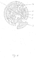
- FIG. 1 shows a gear disc 1 made up of six segments 3.
- the shape of the segments 3 is designed such that when they move in the radial direction on their narrow side they are guided by rollers 4 which are positioned on a concentric circle between the segments 3.
- Each segment 3 is provided with an elongated hole 6 oriented in the radial direction, through which a locking pin 5 anchored in the laterally adjacent guide rings 8a, 8b.
- the locking pin 5 limits the widening of the segments 3 in the radial direction when the control element 7a movable in the axial direction widens the segments 3 at the central bore 2.
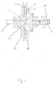
- FIG. 2 shows a gear disk 1a according to the invention in cross-section with the smallest possible disk diameter.
- the segments of the gear disk 1a are guided on both sides below the area serving to receive the traction means 12 in the axial direction, through two guide rings 8a, which are rigidly connected to the drive shaft 9.
- a control element 7a with a conical outer shape so that the tapered end abuts the central bore 2 of the gear disc 1a.
- the control element 7a is pressed by a helical compression spring 10 with constant contact pressure against the segments 3 of the gear disk 1a.
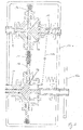
- a single-coupled, continuously variable transmission is shown in cross section in FIG.
- a gear disk 1 a according to the invention is connected to the drive shaft 9.
- a second gear disc 1 b according to the invention is fastened on the output shaft 11.
- the two gear discs are operatively connected by a traction means 12.
- the segments of the second gear disc 1b are widened to the maximum possible diameter by the conical control element 7b, while the gear disc 1a shows its smallest possible diameter.
- the movements of the control elements 7a and 7b are coupled to one another by a lever 13a. If higher drive speeds on the drive shaft 9 lead to an expansion of the gear disk 1a, the control element 7b is simultaneously retracted, the diameter of the gear disk 1b decreasing. Due to this coupling, mediated by the lever 13a, there is a continuous change in the gear ratio.
- a disk 16a of constant diameter is rigidly connected to the output shaft for further power transmission.
- FIG. 4 shows the cross section through a double-coupled, continuously variable transmission.
- this gear At the construction of this gear are three gear discs 1a, 1b bund 1c involved.
- the first gear disk 1a connected to the drive shaft 9 is referred to as the drive disk.
- the two transmission disks 1b and 1c fastened on the parallel transmission shaft are referred to as transmission disks.
- the translation disks 1b, 1c are rigidly connected to the translation shaft 17.
- the control elements 7b, 7c have a central bore 19a, 19b on their expanded side and are rigidly connected to one another at this point by a hollow cylinder 20. This unit is movably mounted on the transmission shaft and is referred to as the control unit 21 of the transmission shaft.
- the double coupling of the gearbox is achieved in that the movably mounted control element 7a of the drive pulley 1a and the control unit 21 movably connected to the transmission axis 17 are coupled to one another by a lever 13b rotatably fixed between the axes.
- the second transmission disc 1c is connected by a traction means 12 to an output disc 18 which is freely supported on the drive shaft 9 and has a constant diameter.
- the disk 18 is rigidly connected outside the housing 14b, which also represents the transmission frame, to a further disk 16b, which is also constant in diameter.
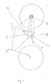
- FIG. 5 schematically shows the simplest form of a continuously variable bicycle transmission that can be achieved with the transmission disc according to the invention.
- the pedals 22 of the bicycle are rigidly connected to the axis 9 of the gear disc 1a.
- the variable-diameter gear disk 1a is connected by means of traction to a disk attached to the hub of the rear wheel 23.
- a tensioning roller 24 is applied to the traction device with slight tension.
- FIG 6 the use of the double-coupled continuously variable transmission as a bicycle transmission is shown schematically.
- the drive shaft 9 is rigidly connected to the pedals 22.
- the gear housing 14b is oriented during installation in the bicycle so that the long side of the transmission shaft 17 points in the direction of the bicycle saddle.
- the disk 16b which is constant in diameter for the transmission of force and which is constant in diameter, is connected by traction means to a disk fastened to the hub 23 and also constant in diameter.
Abstract
Description
Die Erfindung bezieht sich auf ein stufenlos einstellbares Getriebe mit Antriebs- und Abtriebswelle, sowie einer oder mehreren zugmittelaufnehmenden Scheiben (Getriebescheiben), die im Durchmesser stufenlos veränderbar sind.The invention relates to a continuously variable transmission with input and output shaft, as well as one or more pulley-receiving disks (gear disks), the diameter of which can be varied continuously.
Stufenlos einstellbares Getriebe (Variogetriebe), sind Getriebe mit stufenlos veränderlicher Abtriebsdrehzahl, die meist als Zugmittelgetriebe oder Flüssigkeitsgetriebe gestaltet sind. Sie erfüllen die Anforderungen von Fahrzeug- und Maschinenantrieben optimal, weil sie die Anpassung der Drehzahlen an die jeweiligen Betriebsverhältnisse erlauben. Durch stufenlose Änderung des Übersetzungsverhältnisses nehmen diese Getriebe vom Motor die jeweils maximale Drehleistung ab. Auch bei Kleinwagen und Motorrollern werden Keilriemen-Variogetriebe eingesetzt. Dabei kommt es besonders beim Anfahren und Abbremsen zu einer starken Veränderung der Übersetzungsverhältnisse.Infinitely variable gearbox (Vario gearbox) are gearboxes with continuously variable output speed, which are mostly designed as traction mechanisms or liquid gearboxes. They optimally meet the requirements of vehicle and machine drives because they allow the speeds to be adapted to the respective operating conditions. By continuously changing the gear ratio, these gearboxes reduce the maximum turning power from the engine. V-belt Vario transmissions are also used for small cars and scooters. This leads to a strong change in the gear ratios, especially when starting off and braking.
Zum Einsatz bei muskelkraftbetriebenen Fahrzeugen sind aus dem Stand der Technik ein Kettenräderwechselgetriebe (DE-PS 663180) und ein Keilriemen-Variogetriebe (DE 196 09 750 C2) bekannt. Beim erwähnten Kettenräderwechselgetriebe ist eine seitliche, lastproportionale Kupplung des Zugmittels und eine Steuerung des Laufkreises über durch Kurvenscheiben geschaltete Kuppelmäntel mit einer Vorund Rückverlagerung des Einkuppelpunktes vorgesehen. Als Zugmittel wird ein nichtelastisches, metallenes Gelenkband verwendet. Die Kuppelmittel sind als radial und axial bewegliche metallene Klemmbacken ausgebildet. Aufgrund des geringen Reibungsbeiwertes zwischen Zugmittel und Gelenkband muss eine hohe Anpresskraft erzeugt werden, um sicher zu kuppeln. Um zu verhindern, dass der Kuppelmechanismus nicht selbsthemmend wird und nicht mehr freikoppelt, sind in den Kurvenscheiben Wälzkörper installiert. Bei dieser Vorrichtung ist nur ein geringer Teil der Zugmittelkraft für die Erzeugung der Kuppelkraft nutzbar, so dass zwangsläufig tangentialer Schlupf zwischen Kuppelmittel und Zugmittel beim Ein- und Auslaufen auftritt.For use in muscle-powered vehicles, a sprocket change transmission (DE-PS 663180) and a V-belt variable transmission (DE 196 09 750 C2) are known from the prior art. In the chain sprocket change transmission mentioned, a lateral, load-proportional coupling of the traction means and a control of the running circuit via coupling sleeves connected by cam disks with a forward and backward displacement of the coupling point are provided. A non-elastic, metal hinge is used as a traction device. The coupling means are designed as radially and axially movable metal clamping jaws. Due to the low coefficient of friction A high contact pressure must be generated between the traction device and the hinge in order to couple securely. Rolling elements are installed in the cams to prevent the coupling mechanism from becoming self-locking and from freeing up. With this device, only a small part of the traction force can be used to generate the coupling force, so that tangential slippage between the coupling means and traction device inevitably occurs during the entry and exit.
Beim Keilriemen-Variogetriebe wird die stufenlose Änderung des Getriebe-Übersetzungsverhältnisses ebenfalls durch eine stufenlose Veränderung des Zugmittellaufkreisradius an mindestens einer Triebdoppelscheibe erreicht. Bei radialer Führung des Zugmittels wird auch hier die Kraftübertragung zwischen dem Zugmittel und den Triebdoppelscheiben durch seitlich am Zugmittel angreifende Kuppelmittel erreicht. Die an den Planscheiben angeordneten Kuppelmittel sind tangential und radial beweglich gelagert. Sie sind zur Erreichung der lastabhängigen Kraftübertragung unter Last selbst unterstützend bzw. selbsthemmend ausgeführt und kuppeln am Auslaufpunkt selbsttätig ab. Durch eine aufwendige und wartungsintensive Steuerung setzen die Kuppelmittel die tangentialen und/oder radialen Riemenbewegungen und -kräfte in axiale Spreizbewegungen und damit in seitliche Druckkräfte in Form einer axialen Anpresskraft auf die Riemenflanke um. Die radiale Führung des Zugmittels wird bei diesem Getriebe erreicht durch eine am Steuerarm befestigte Tastrolle, die innenseitig am Zugmittel anliegt und abhängig von der Stellung des Steuerarms dem Zugmittel- Laufkreisradius vorgibt, sowie durch Steuerstifte, die in axialer Richtung verfahrbar sind. Die Steuerstifte führen das Zugmittel bei der Veränderung des Zugmittel-Laufkreisradius, sind jedoch nicht an der durch das Zugmittel vermittelten Kraftübertragung beteiligt. Nachteilig ist, dass diese Steuerung eine Vielzahl von Verschleißteilen beinhaltet. Für einen guten Rundlauf werden beispielsweise 10 Kuppelmittel pro Triebscheibe vorgeschlagen. Neben der Verschleißempfindlichkeit der Kuppelmittel ist außerdem nachteilig, dass diese mit beträchtlichem Zeitaufwand eingestellt werden müssen.With the V-belt Vario transmission, the infinitely variable change in the gear ratio is also achieved by an infinitely variable change in the traction mechanism radius on at least one drive double pulley. With radial guidance of the traction means, the force transmission between the traction means and the drive double disks is also achieved here by coupling means acting laterally on the traction means. The coupling means arranged on the face plates are tangentially and radially movable. They are self-supporting or self-locking to achieve the load-dependent power transmission under load and disconnect automatically at the outlet point. Thanks to a complex and maintenance-intensive control, the coupling means convert the tangential and / or radial belt movements and forces into axial spreading movements and thus into lateral pressure forces in the form of an axial contact force on the belt flank. The radial guidance of the traction device is achieved in this transmission by a feeler roller attached to the control arm, which rests on the inside of the traction device and, depending on the position of the control arm, specifies the traction device radius, and by control pins that can be moved in the axial direction. The control pins guide the traction device when changing the traction device radius, but are not involved in the power transmission mediated by the traction device. The disadvantage is that this control includes a variety of wear parts. For example, 10 coupling means per drive pulley are suggested for good concentricity. In addition to the wear sensitivity of the coupling means, it is also disadvantageous that they have to be set up with a considerable amount of time.
Der Erfindung liegt das Problem der Konstruktion von stufenlos einstellbaren Getrieben für verschiedene Einsatzbereiche zugrunde, deren Getriebescheiben im Durchmesser stufenlos veränderbar sind, so dass eine stufenlose Änderung des Getriebe-Übersetzungsverhältnisses möglich ist. Dabei soll ganz auf seitliche mit Klemmkraft am Zugmittel angreifende Kuppelmittel verzichtet werden.The invention is based on the problem of the construction of continuously variable transmissions for different areas of application, the transmission disks of which are continuously variable in diameter, so that a continuous change in the gear ratio is possible. In this case, lateral coupling means which act on the traction means with clamping force should be dispensed with entirely.
Erfindungsgemäß wird die Aufgabe ausgehend von einem gattungsgemäßen Variogetriebe (DE 196 09 750 C2), mit seitlich am Zugmittel angreifenden Kuppelmitteln, dadurch gelöst, dass die Getriebescheiben segmentartig aufgebaut sind und eine mittige Bohrung aufweisen, an die ein in axialer Richtung beweglich gelagertes Steuerelement mit konischer Außenform anliegt, die Segmente in radialer Richtung stufenlos beweglich sind, der übersetzungswirksame Durchmesser jeder Getriebescheibe durch die Verschiebung des Steuerelementes in axialer Richtung unter Aufweitung der mittigen Bohrung zwischen den Segmenten regulierbar ist, wobei die Segmente in axialer Richtung beidseitig geführt und angetrieben sind.According to the invention, the object is achieved on the basis of a generic variable transmission (
Der Kerngedanke der Erfindung besteht darin, dass der Zugmittel-Laufkreisradius einer segmentartig aufgebauten Getriebescheibe durch ein in axialer Richtung beweglich gelagertes Steuerelement mit konischer Außenform stufenlos einstellbar ist, wobei es bei höheren Drehzahlen zu einer Aufweitung der Segmente und damit des Scheibendurchmessers kommt. Verursacht wird diese Aufweitung durch das mit Federdruck anliegende Steuersegment. Die Segmente jeder Getriebescheibe sind unterhalb des zur Aufnahme des Zugmittel dienenden äußeren Bereichs in axialer Richtung beidseitig geführt, durch zwei Führringe, die mit der Antriebswelle starr verbunden sind. Die Segmente der Getriebescheibe, das Steuerelement und die mit der Achse starr verbundenen beidseitig anliegenden Führringe bilden so zusammen, bei entsprechender Lagerung, eine frei drehbare Einheit.The main idea of the invention is that the traction-circle radius of a gear disc of segment-like construction can be infinitely adjusted by a control element with a conical outer shape that is movably mounted in the axial direction, the segments and thus the disc diameter being widened at higher speeds. This expansion is caused by the control segment that rests with spring pressure. The segments of each transmission disk are guided on both sides below the outer area serving to receive the traction means in the axial direction, by means of two guide rings which are rigidly connected to the drive shaft. The segments of the gear disc, the control element and the guide rings which are rigidly connected to the axle on both sides form a freely rotatable unit together with appropriate storage.
In der normalen Ausführungsform der erfindungsgemäßen Getriebescheibe ist die Form der Segmente so gestaltet, dass sie bei ihrer Bewegung in radialer Richtung an ihrer Schmalseite durch Rollen geführt werden, die auf einem konzentrischen Kreis zwischen den Segmenten positioniert sind. Jedes Segment ist mit einem in radialer Richtung ausgerichteten Langloch versehen, durch das ein in den seitlich anliegenden Führungsringen verankerter Sicherungsstift führt. Während der minimale Zugmittel-Laufkreisradius der Getriebescheibe durch die Entfernung des Steuerelementes aus der mittigen Bohrung einstellbar ist, begrenzt der genannte Sicherungsstift die maximale Aufweitung der einzelnen Segmente beim Verschieben des Steuerelementes in axialer Richtung. Die aufgeweiteten Segmente liegen dabei auf der konischen Außenseite des Steuerelementes auf. Da das Steuerelement mit konstantem Anpressdruck, der durch eine in der hohlzylindrischen Antriebswelle befestigten Schraubendruckfeder geschaffen wird, seitlich am unteren Ende der Segmente anliegt, kommt es bei zunehmenden Drehzahlen zu einer Aufweitung der Getriebescheibe. Verbunden damit ist eine stufenlose Änderung des Getriebe-Übersetzungsverhältnisses.In the normal embodiment of the gear disk according to the invention, the shape of the segments is designed such that they are guided on their narrow side by their movement in the radial direction by rollers which are positioned on a concentric circle between the segments. Each segment is provided with an elongated hole aligned in the radial direction, through which a locking pin is anchored in the guide rings lying on the side. While the minimum traction circle radius of the gear disc can be adjusted by removing the control element from the central hole, the locking pin limits the maximum expansion of the individual segments when the control element is moved in the axial direction. The widened segments lie on the conical outside of the control element. Since the control element with constant contact pressure, which is created by a helical compression spring fastened in the hollow cylindrical drive shaft, rests laterally at the lower end of the segments, the transmission disc expands with increasing speeds. This is associated with a continuous change in the gear ratio.
Die einfachste Ausführungsform eines Getriebes unter Verwendung der erfindungsgemäßen Getriebescheibe erhält man, in dem man die Getriebescheibe mit einer im Durchmesser konstanten und auf einer parallel verlaufenden Abtriebswelle befestigten Abtriebsscheibe durch Zugmittel verbindet. Die entsprechende Abtriebswelle könnte beispielsweise die Nabe am Hinterrad eines Fahrrades sein. Um zu vermeiden, dass das Zugmittel bei abnehmendem Durchmesser der Antriebsscheibe durchhängt, wird das Zugmittel von einer zusätzlich angebrachten Spannrolle mit leichter Spannung geführt.The simplest embodiment of a transmission using the transmission disc according to the invention is obtained by the Gear disc with a constant diameter in diameter and attached to a parallel output shaft connected by traction means. The corresponding output shaft could, for example, be the hub on the rear wheel of a bicycle. In order to prevent the traction device from sagging when the diameter of the drive pulley decreases, the traction device is guided by an additionally attached tensioning roller with slight tension.
Die segmentartig aufgebaute Getriebescheibe lässt sich bei entsprechender Anbringung auf Antriebs- und Abtriebswellen zum modulartigen Aufbau von gekoppelten Getrieben nutzen. Ein erfindungsgemäßes einfach-gekoppeltes und ein erfindungsgemäßes zweifach-gekoppeltes stufenlos schaltbares Getriebe werden im folgenden besprochen.The segmented gear disc can be used for the modular construction of coupled gearboxes if it is attached to the input and output shafts. An inventive single-coupled and an inventive double-coupled continuously variable transmission are discussed below.
In einer einfachen Ausführungsform erhält man unter Nutzung zweier Getriebescheiben, die auf zueinander paralleler Antriebs- und Abtriebswelle zugmittelverbunden befestigt sind, ein einfach-gekoppeltes stufenlos einstellbares Getriebe. Dabei ist sowohl die mit der Antriebswelle in Verbindung stehende Getriebescheibe (Antriebsscheibe), als auch die mit der Abtriebswelle in Verbindung stehende Getriebescheibe (Abtriebsscheibe) mit einem Steuerelement versehen. Entscheidend für die Steuerung des Getriebes ist, dass das Steuerelement auf der Antriebswelle mit dem Steuerelement auf der Abtriebswelle durch einen zwischen den Achsen drehbar fixierten Hebel mechanisch miteinander gekoppelt sind. Im Hinblick auf den Außendurchmesser der Getriebescheiben kann aufgrund der Koppelung von einer inversen Steuerung der beiden Getriebescheiben gesprochen werden: Während die Segmente der Antriebsscheibe bei höheren Drehzahlen durch das Steuerelement zu größerem Durchmesser aufgeweitet werden, wird das Steuerelement der Abtriebsscheibe von deren Segmenten wegbewegt, so dass sich diese nach innen bewegen und die Abtriebsscheibe einen geringeren Außendurchmesser aufweist. Durch das Verschieben des drehbar fixierten Hebels kann die Regulation des einfach-gekoppelten stufenlos einstellbaren Getriebes von außen zusätzlich beeinflusst werden.In a simple embodiment, a single-coupled, infinitely variable transmission is obtained using two transmission disks, which are fastened on a drive means connected to each other in parallel with the drive means and output shaft. Both the gear disc (drive disc) connected to the drive shaft and the gear disc (output disc) connected to the output shaft are provided with a control element. It is crucial for the control of the transmission that the control element on the drive shaft is mechanically coupled to the control element on the output shaft by a lever rotatably fixed between the axes. With regard to the outer diameter of the gear discs, due to the coupling One speaks of an inverse control of the two transmission disks: While the segments of the drive pulley are expanded to a larger diameter by the control element at higher speeds, the control element of the driven pulley is moved away from its segments so that they move inwards and the driven pulley has a smaller outer diameter having. By moving the rotatably fixed lever, the regulation of the simply coupled, continuously variable transmission can be influenced from the outside.
Zur Installation des einfach-gekoppelten stufenlos einstellbaren Getriebes an einer Maschine oder an einem Fahrrad wird das Getriebe in einem Gehäuse installiert, das zugleich das Getriebegestell bildet. Zur Übertragung der Kraft an das Hinterrad des Fahrrades oder eine andere nicht zum Getriebe gehörende Scheibe wird außerhalb des Gehäuses eine zusätzliche Scheibe befestigt, die einen konstantem Durchmesser aufweist und mit der Abtriebswelle des Getriebes verbunden ist.To install the simply coupled, continuously variable transmission on a machine or on a bicycle, the transmission is installed in a housing that also forms the transmission frame. To transmit the power to the rear wheel of the bicycle or another disc not belonging to the transmission, an additional disc is attached outside the housing, which has a constant diameter and is connected to the output shaft of the transmission.
In einer besonderen Ausführungsform des stufenlos einstellbaren Getriebes, nämlich in Form eines zweifach-gekoppelten Getriebes, kommt die Eignung der erfindungsgemäßen Getriebescheibe zum modulartigen Aufbau von stufenlos einstellbaren Getriebe deutlich zum Ausdruck. Beim zweifach-gekoppelten stufenlos einstellbaren Getriebe werden auf zwei konstant voneinander beabstandeten und parallel angeordneten Wellen zwei sich jeweils paarweise direkt gegenüberliegende Getriebescheiben durch Zugmittel bewegungsmäßig gekoppelt. Die erste mit der Antriebswelle verbundene Getriebescheibe wird als Antriebsscheibe bezeichnet und entspricht im Aufbau der erfindungsgemäßen Getriebescheibe. Auf der parallel verlaufenden Übersetzungswelle ist eine weitere Getriebescheibe befestigt. Diese beiden Scheiben werden als Übersetzungsscheiben bezeichnet und entsprechen im Aufbau ebenfalls der erfindungsgemäßen Getriebescheibe. Die Übersetzungsscheiben sind mit der Übersetzungswelle starr verbunden. Die Steuerelemente der Übersetzungsscheiben haben ebenfalls eine konische Außenform und weisen auf ihrer aufgeweiteten Seite eine mittige Bohrung auf und sind jeweils auf dieser aufgeweiteten Seite durch einen Hohlzylinder starr miteinander verbunden. Diese durch den Hohlzylinder geschaffene Einheit ist beweglich auf der Übersetzungswelle gelagert und wird als Steuereinheit der Übersetzungswelle bezeichnet. Aufgrund der konstanten Beabstandung der Steuerelemente auf der Übersetzungswelle sind die Übersetzungsscheiben in der Einstellung ihrer übersetzungswirksamen Durchmesser voneinander abhängig.In a special embodiment of the continuously variable transmission, namely in the form of a double-coupled transmission, the suitability of the transmission disc according to the invention for the modular construction of continuously variable transmissions is clearly expressed. In the case of the double-coupled continuously variable transmission, two transmission disks which are directly opposite each other in pairs are coupled in terms of movement by means of traction means on two shafts which are constantly spaced apart and arranged in parallel. The first gear disc connected to the drive shaft is referred to as a drive pulley and corresponds in structure to the gear pulley according to the invention. Another gear washer is attached to the parallel transmission shaft. These two disks are referred to as transmission disks and also correspond in structure to the transmission disk according to the invention. The translation disks are rigidly connected to the translation shaft. The control elements of the transmission disks also have a conical outer shape and have a central bore on their flared side and are rigidly connected to one another on this flared side by a hollow cylinder. This unit created by the hollow cylinder is movably supported on the transmission shaft and is referred to as the control unit of the transmission shaft. Due to the constant spacing of the control elements on the transmission shaft, the transmission disks are dependent on one another in the setting of their translation-effective diameters.
Die zweifache Koppelung des Getriebes kommt nun dadurch zustande, dass das beweglich gelagerte Steuerelement der Antriebsscheibe und die beweglich mit der Übersetzungsachse verbundene Steuereinheit durch einen zwischen den Achsen drehbar fixierten Hebel miteinander gekoppelt sind. Kommt es also bei höheren Drehzahlen zu einer Aufweitung der Antriebsscheibe, so wird die axiale Bewegung des Steuerelementes der Antriebsscheibe in Richtung der Segmente der Antriebsscheibe durch den zwischen den Achsen befestigten Hebel auf die Steuereinheit der Übersetzungswelle übertragen. Aufgrund der bewegungsmäßigen Koppelung der Steuerelemente ist die Aufweitung der Antriebsscheibe verbunden mit einer Verringerung des Durchmessers auf der gegenüberliegenden Übersetzungsscheibe, die mit der Antriebsscheibe durch Zugmittel verbunden ist. Bedingt durch die starre Verbindung der beiden Steuerelemente auf der Übersetzungswelle hat die Bewegung der Steuereinheit auch Auswirkung auf den Durchmesser der zweiten Übersetzungsscheibe: Wird der Durchmesser der mit der Antriebsscheibe verbundenen Übersetzungsscheibe zu kleineren Durchmessern reguliert, so wird zwangsweise der Durchmesser der zweiten Übersetzungsscheibe vergrößert. Da beide Übersetzungsscheiben auf der Übersetzungswelle starr miteinander verbunden sind, haben sie die gleiche Drehzahl, aber stark unterschiedliche Außendurchmesser. Die Koppelung ist derart, dass bei maximalem Außendurchmesser der Antriebsscheibe auch die zweite Übersetzungsscheibe ihren maximalen Außendurchmesser erreicht und somit auf die im Durchmesser konstante und frei auf der Antriebswelle gelagerte Abtriebsscheibe durch Zugmittelverbindung die maximale Drehzahlen erzeugt. Zur Spannung des Zugmittels bei abnehmendem Durchmesser der zweiten Übersetzungsscheibe liegt eine Spannrolle mit leichter Spannung am Zugmittel an.The double coupling of the gearbox now comes about because the movably mounted control element of the drive pulley and the control unit movably connected to the translation axis are coupled to one another by a lever which is rotatably fixed between the axes. If there is an expansion of the drive pulley at higher speeds, the axial movement of the control element of the drive pulley in the direction of the segments of the drive pulley is transmitted to the control unit of the transmission shaft by the lever fastened between the axles. Due to the movement coupling of the control elements, the expansion of the drive pulley is associated with a reduction in the diameter on the opposite transmission pulley, which is connected to the drive pulley by traction means. Due to the rigid connection of the two controls on the transmission shaft, the movement of the control unit also has an effect on the diameter of the second transmission disk: if the diameter of the transmission disk connected to the drive disk is regulated to smaller diameters, the diameter of the second transmission disk is inevitably increased. Since both transmission discs are rigidly connected to each other on the transmission shaft, they have the same speed, but very different outside diameters. The coupling is such that with a maximum outer diameter of the drive disk, the second transmission disk also reaches its maximum outer diameter and thus generates the maximum speeds on the driven disk, which is constant in diameter and freely supported on the drive shaft, by means of a traction device connection. For tensioning the traction device with a decreasing diameter of the second transmission disc, a tensioning roller is in contact with the traction device with slight tension.
Diese in ihrem Zusammenwirken beschriebenen wesentlichen Bestandteile des zweifach-gekoppelten stufenlos einstellbaren Getriebes werden in der beschriebenen Anordnung durch ein Gehäuse umgeben, das zugleich das Getriebegestell darstellt. Zur Kraftübertragung auf einen nicht zum Getriebe gehörenden Antrieb ist die auf der Antriebswelle frei gelagerte und im Durchmesser konstante Getriebescheibe außerhalb des Gehäuses mit einer weiteren, im Durchmesser ebenfalls konstanten Scheibe starr verbunden.These essential components of the double-coupled continuously variable transmission described in their interaction are surrounded in the arrangement described by a housing which also represents the transmission frame. For power transmission to a drive that does not belong to the gearbox, the gear disk, which is freely supported on the drive shaft and has a constant diameter, is rigidly connected outside the housing to a further disk which is also constant in diameter.
Die zur Herstellung der Wirkverbindung zwischen den Getriebescheiben bzw. zwischen den Getriebe- und Abtriebsscheiben eingesetzten Zugmittel sind vorzugsweise Keil- oder Flachriemen. Für die Kraftübertragung ausgehend von den außerhalb des Getriebegehäuses liegenden, im Durchmesser konstanten Scheiben, eignen sich als Zugmittel Keilriemen, Flachriemen, Zahnriemen, Zahnketten oder Rollketten.The traction means used to establish the operative connection between the transmission pulleys or between the transmission and driven pulleys are preferably V-belts or flat belts. Suitable for the power transmission from the disks outside the gear housing, which have a constant diameter, are suitable V-belts, flat belts, toothed belts, toothed chains or roller chains as traction devices.
Die erfindungsgemäße Getriebescheibe und die darauf aufbauenden Getriebeformen eignet sich auch zum Antrieb von Fahrrädern. Die einfachste Form eines entsprechenden Fahrradgetriebes ist dadurch gekennzeichnet, dass eine erfindungsgemäße Getriebescheibe als Antriebsscheibe mit den Pedalen in Verbindung steht und durch Zugmittel mit einer auf der Nabe des Hinterrades befestigten und im Durchmesser konstanten Scheibe verbunden ist. Um das Zugmittel bei kleineren Durchmessern der Antriebsscheibe unter Spannung zu halten, liegt am Zugmittel eine Spannrolle mit leichter Spannung an.The gear disk according to the invention and the gear shapes based thereon are also suitable for driving bicycles. The simplest form of a corresponding bicycle transmission is characterized in that a transmission disc according to the invention is connected to the pedals as a drive disc and is connected by traction means to a disc fixed on the hub of the rear wheel and of constant diameter. In order to keep the traction device under tension with smaller diameters of the drive pulley, a tension roller with light tension is applied to the traction device.
Ein einfach-gekoppeltes stufenlos einstellbares Fahrradgetriebe kann mit der erfindungsgemäßen Getriebescheibe auf zwei verschiedene Arten konstruiert werden. Im ersten Fall wird eine erfindungsgemäße Getriebescheibe als Antriebsscheibe mit den Pedalen des Zwei-Rades verbunden. Eine zweite baugleiche Getriebescheibe wird über ihre Welle starr mit der Nabe des Hinterrades verbunden. Weil der Rahmen des Fahrrades hinderlich wäre, sind die Steuerelemente der beiden Getriebescheiben in diesem Fall nicht durch einen Hebel, sondern durch Schaltzüge wirkverbunden.A simply coupled, continuously adjustable bicycle transmission can be constructed in two different ways with the transmission disc according to the invention. In the first case, a transmission disk according to the invention is connected as a drive disk to the pedals of the two-wheel. A second identical gear disc is rigidly connected to the hub of the rear wheel via its shaft. Because the frame of the bicycle would be a hindrance, the control elements of the two transmission disks are in this case not connected by a lever, but by shift cables.
Die zweite Möglichkeit zur Installation eines einfach-gekoppelten stufenlos einstellbaren Getriebes am Fahrrad besteht in der Verwendung des beschriebenen erfindungsgemäßen einfach-gekoppelten stufenlos einstellbaren Getriebes. Dabei werden die Pedale an der Antriebswelle des Getriebes befestigt und die außerhalb des Getriebegehäuses liegende Scheibe wird durch Zugmittel mit der Nabe des Hinterrades verbunden. Ein Fahrrad mit zweifach-gekoppelter stufenloser Schaltung erhält man durch den entsprechenden Einbau des erfindungsgemäßen zweifach-gekoppelten stufenlos einstellbaren Getriebes.The second option for installing a simply coupled, continuously variable transmission on the bicycle is to use the described, simply coupled, continuously variable transmission. The pedals are attached to the drive shaft of the gearbox and those outside the gearbox the disc is connected to the hub of the rear wheel by means of traction. A bicycle with a double-coupled continuously variable transmission can be obtained by the corresponding installation of the double-coupled continuously variable transmission according to the invention.
Weitere Einzelheiten und Merkmale der Erfindung lassen sich dem nachfolgenden Beschreibungsteil entnehmen. Darin werden mögliche Ausführungsbeispiele der auf die erfindungsgemäße Getriebescheibe aufbauenden Getriebeformen anhand von Zeichnungen näher erläutert.Further details and features of the invention can be found in the following description. In it, possible exemplary embodiments of the gear forms based on the gear disc according to the invention are explained in more detail with reference to drawings.
In Figur 1 ist eine aus sechs Segmenten 3 aufgebaute Getriebescheibe 1 abgebildet. Die Form der Segmente 3 ist so gestaltet, dass sie bei ihrer Bewegung in radialer Richtung an ihrer Schmalseite durch Rollen 4 geführt werden, die auf einem konzentrischen Kreis zwischen den Segmenten 3 positioniert sind. Jedes Segment 3 ist mit einem in radialer Richtung ausgerichteten Langloch 6 versehen, durch das ein in den seitlich anliegenden Führungsringen 8a, 8b verankerter Sicherungsstift 5 führt. Der Sicherungsstift 5 begrenzt die Aufweitung der Segmente 3 in radialer Richtung, wenn das in axialer Richtung bewegliche Steuerelement 7a die Segmente 3 an der mittigen Bohrung 2 aufweitet.FIG. 1 shows a gear disc 1 made up of six
In Figur 2 ist eine erfindungsgemäße Getriebescheibe 1a im Querschnitt mit dem kleinstmöglichen Scheibendurchmesser zu sehen. Die Segmente der Getriebescheibe 1a sind unterhalb des zur Aufnahme des Zugmittels 12 dienenden Bereichs in axialer Richtung beidseitig geführt, durch zwei Führringe 8a, die mit der Antriebswelle 9 starr verbunden sind. In der Antriebswelle 9 ist ein Steuerelement 7a mit konischer Außenform so gelagert, dass das verjüngte Ende an der mittigen Bohrung 2 der Getriebescheibe 1a anliegt. Das Steuerelement 7a wird durch eine Schraubendruckfeder 10 mit konstantem Anpressdruck gegen die Segmente 3 der Getriebescheibe 1a gepresst. Die beschriebenen Bestandteile: die Segmente der Getriebescheibe 1a, das Steuerelement 7a und die mit der Achse 9 starr verbundenen beidseitig anliegenden Führringe 8a und 8b bilden zusammen eine Einheit, die bei entsprechender Lagerung frei drehbar ist.FIG. 2 shows a gear disk 1a according to the invention in cross-section with the smallest possible disk diameter. The segments of the gear disk 1a are guided on both sides below the area serving to receive the traction means 12 in the axial direction, through two guide rings 8a, which are rigidly connected to the
In Figur 3 ist ein einfach-gekoppeltes stufenlos einstellbares Getriebe im Querschnitt gezeigt. Dabei ist eine erfindungsgemäße Getriebescheibe 1 a mit der Antriebswelle 9 verbunden. Parallel dazu ist eine zweite erfindungsgemäße Getriebescheibe 1 b auf der Abtriebswelle 11 befestigt. Die beiden Getriebescheiben sind durch ein Zugmittel 12 wirkverbunden. Die Segmente der zweiten Getriebescheibe 1b sind durch das konische Steuerelement 7b zum maximal möglichen Durchmesser aufgeweitet, während die Getriebescheibe 1a ihren kleinstmöglichen Durchmesser zeigt. Die Bewegungen der Steuerelemente 7a und 7b sind durch einen Hebel 13a miteinander gekoppelt. Wenn es durch höhere Antriebsdrehzahlen an der Antriebswelle 9 zu einer Aufweitung der Getriebescheibe 1a kommt, so wird gleichzeitig das Steuerelement 7b zurückgefahren, wobei der Durchmesser der Getriebescheibe 1b abnimmt. Aufgrund dieser, durch den Hebel 13a vermittelten Kopplung kommt es zu einer stufenlosen Änderung des Getriebe-Übersetzungsverhältnisses. Außerhalb des Getriebegehäuses 14a ist zur weiteren Kraftübertragung eine im Durchmesser konstante Scheibe 16a starr mit der Abtriebswelle verbunden.A single-coupled, continuously variable transmission is shown in cross section in FIG. A gear disk 1 a according to the invention is connected to the
In Figur 4 ist der Querschnitt durch ein zweifach-gekoppeltes stufenlos einstellbares Getriebes gezeigt. Am Aufbau dieses Getriebes sind drei erfindungsgemäße Getriebescheiben 1a, 1b bund 1c beteiligt. Die erste mit der Antriebswelle 9 verbundene Getriebescheibe 1a wird als Antriebsscheibe bezeichnet. Die beiden auf der parallel verlaufenden Übersetzungswelle befestigten Getriebescheiben 1b und 1c werden als Übersetzungsscheiben bezeichnet. Die Übersetzungsscheiben 1b, 1c sind mit der Übersetzungswelle 17 starr verbunden. Die Steuerelemente 7b, 7c weisen auf ihrer aufgeweiteten Seite eine mittige Bohrung 19a, 19b auf und sind an dieser Stelle durch einen Hohlzylinder 20 starr miteinander verbunden. Diese Einheit ist beweglich auf der Übersetzungswelle gelagert und wird als Steuereinheit 21 der Übersetzungswelle bezeichnet. Die zweifache Koppelung des Getriebes kommt dadurch zustande, dass das beweglich gelagerte Steuerelement 7a der Antriebsscheibe 1a und die beweglich mit der Übersetzungsachse 17 verbundene Steuereinheit 21 durch einen zwischen den Achsen drehbar fixierten Hebel 13b miteinander gekoppelt sind. Die zweite Übersetzungsscheibe 1c ist durch Zugmittel 12 mit einer auf der Antriebswelle 9 frei gelagerten und im Durchmesser konstanten Abtriebsscheibe 18 verbunden. Zur weiteren Kraftübertragung ist die Scheibe 18 außerhalb des Gehäuses 14b, das zugleich das Getriebegestell darstellt, mit einer weiteren im Durchmesser ebenfalls konstanten Scheibe 16b starr verbunden.FIG. 4 shows the cross section through a double-coupled, continuously variable transmission. At the construction of this gear are three gear discs 1a, 1b bund 1c involved. The first gear disk 1a connected to the
In Figur 5 ist die einfachste mit der erfindungsgemäßen Getriebescheibe zu erreichende Form eines stufenlos einstellbaren Fahrradgetriebes schematisch gezeigt. Die Pedale 22 des Fahrrads sind dabei mit der Achse 9 der Getriebescheibe 1a starr verbunden. Die im Durchmesser variable Getriebescheibe 1a ist durch Zugmittel mit einer an der Nabe des Hinterrades 23 befestigten Scheibe verbunden. Zur Spannung des Zugmittels bei abnehmendem Durchmesser der Getriebescheibe 1a liegt am Zugmittel eine Spannrolle 24 mit leichter Spannung an.FIG. 5 schematically shows the simplest form of a continuously variable bicycle transmission that can be achieved with the transmission disc according to the invention. The
In Figur 6 ist die Verwendung des zweifach-gekoppelten stufenlos einstellbaren Getriebes als Fahrradgetriebe schematisch gezeigt. Die Antriebswelle 9 ist dabei starr mit den Pedalen 22 verbunden. Das Getriebegehäuse 14b ist beim Einbau in das Fahrrad so orientiert, dass die Längsseite der Übersetzungswelle 17 in Richtung Fahrradsattel zeigt. Die zur Kraftübertragung außerhalb des Getriebegehäuses 14b liegende Scheibe 16b, die im Durchmesser konstant ist, ist durch Zugmittel mit einer an der Nabe 23 befestigten und im Durchmesser ebenfalls konstanten Scheibe verbunden.In Figure 6, the use of the double-coupled continuously variable transmission as a bicycle transmission is shown schematically. The
Claims (21)
Applications Claiming Priority (2)
| Application Number | Priority Date | Filing Date | Title |
|---|---|---|---|
| DE2003111432 DE10311432A1 (en) | 2003-03-15 | 2003-03-15 | Infinitely adjustable gear |
| DE10311432 | 2003-03-15 |
Publications (2)
| Publication Number | Publication Date |
|---|---|
| EP1460309A2 true EP1460309A2 (en) | 2004-09-22 |
| EP1460309A3 EP1460309A3 (en) | 2006-08-02 |
Family
ID=32797920
Family Applications (1)
| Application Number | Title | Priority Date | Filing Date |
|---|---|---|---|
| EP03028787A Withdrawn EP1460309A3 (en) | 2003-03-15 | 2003-12-13 | Continuously variable transmission |
Country Status (2)
| Country | Link |
|---|---|
| EP (1) | EP1460309A3 (en) |
| DE (1) | DE10311432A1 (en) |
Cited By (7)
| Publication number | Priority date | Publication date | Assignee | Title |
|---|---|---|---|---|
| EP2988022A3 (en) * | 2014-08-05 | 2016-03-02 | Deere & Company | Variable-speed belt drive assembly |
| CN106218240A (en) * | 2015-06-02 | 2016-12-14 | 富士通电子零件有限公司 | Printing equipment |
| NL2017150B1 (en) * | 2016-07-11 | 2018-01-17 | Drive Tech Holland Ltd | Transmission and vehicle provided with such a transmission. |
| CN110762172A (en) * | 2018-07-25 | 2020-02-07 | 重庆宗申无级变速传动有限公司 | Three-shaft speed-regulating conical disc type continuously variable transmission |
| CN111448405A (en) * | 2017-07-13 | 2020-07-24 | 先进传输系统控股有限公司 | Pulley and transmission system |
| US10753456B2 (en) | 2016-04-20 | 2020-08-25 | Ge Avio S.R.L. | Oil transfer unit for transferring oil between a stationary part and a rotating part |
| CN113483077A (en) * | 2021-07-29 | 2021-10-08 | 刘小梅 | Mechanical belt wheel and working method thereof |
Citations (2)
| Publication number | Priority date | Publication date | Assignee | Title |
|---|---|---|---|---|
| DE663180C (en) | 1936-06-28 | 1938-07-30 | Hofmann Walter | Chain wheel change gear with stepless regulation |
| DE19609750C2 (en) | 1996-03-13 | 1998-07-30 | Edgar Loehr | Infinitely adjustable gear |
Family Cites Families (13)
| Publication number | Priority date | Publication date | Assignee | Title |
|---|---|---|---|---|
| DE114379C (en) * | ||||
| GB191125516A (en) * | 1912-05-16 | 1913-01-16 | Dron & Lawson Ltd | Improvements in and relating to Variable Speed Gears. |
| US1374439A (en) * | 1919-10-25 | 1921-04-12 | Morris I Kopple | Variable-speed device |
| GB149723A (en) * | 1919-11-21 | 1920-08-26 | Henry Barclay Allan | An improved variable speed gear |
| DE634643C (en) * | 1933-07-09 | 1936-09-01 | Kamill Huebner | Change gears with V-belts, ropes or the like. |
| FR1098110A (en) * | 1954-01-06 | 1955-07-18 | Improvements to continuous gear changes | |
| NL6507654A (en) * | 1965-06-15 | 1966-12-16 | ||
| ES8405122A1 (en) * | 1981-09-09 | 1984-05-16 | Ybern Miro Pedro | Transmission ratio variators |
| US4842569A (en) * | 1987-11-16 | 1989-06-27 | Recreational Accessoried Corporation | Bicycle transmission having infinitely variable drive ratio |
| DE3914902A1 (en) * | 1989-05-05 | 1990-11-08 | Ernst Wollenschneider | Variable speed drive for bicycle - uses V=belts and split pulleys to produce stepless variation of speed ratio |
| GB2239063A (en) * | 1989-12-07 | 1991-06-19 | Fraser Milne | Variable speed drive comprising a pulley with radially movable parts |
| US5492506A (en) * | 1994-10-14 | 1996-02-20 | Lorance; R. Dennis | Continuously variable pulley |
| DE4446886A1 (en) * | 1994-12-27 | 1996-07-04 | Samy Dipl Ing Kamal | Continuously variable drive mechanism for cycle or motorcycle |
-
2003
- 2003-03-15 DE DE2003111432 patent/DE10311432A1/en not_active Withdrawn
- 2003-12-13 EP EP03028787A patent/EP1460309A3/en not_active Withdrawn
Patent Citations (2)
| Publication number | Priority date | Publication date | Assignee | Title |
|---|---|---|---|---|
| DE663180C (en) | 1936-06-28 | 1938-07-30 | Hofmann Walter | Chain wheel change gear with stepless regulation |
| DE19609750C2 (en) | 1996-03-13 | 1998-07-30 | Edgar Loehr | Infinitely adjustable gear |
Cited By (10)
| Publication number | Priority date | Publication date | Assignee | Title |
|---|---|---|---|---|
| EP2988022A3 (en) * | 2014-08-05 | 2016-03-02 | Deere & Company | Variable-speed belt drive assembly |
| CN106218240A (en) * | 2015-06-02 | 2016-12-14 | 富士通电子零件有限公司 | Printing equipment |
| CN106218240B (en) * | 2015-06-02 | 2018-11-27 | 富士通电子零件有限公司 | Printing equipment |
| US10753456B2 (en) | 2016-04-20 | 2020-08-25 | Ge Avio S.R.L. | Oil transfer unit for transferring oil between a stationary part and a rotating part |
| NL2017150B1 (en) * | 2016-07-11 | 2018-01-17 | Drive Tech Holland Ltd | Transmission and vehicle provided with such a transmission. |
| WO2018012966A1 (en) * | 2016-07-11 | 2018-01-18 | Drive Technology Holland Ltd. | Transmission and vehicle provided with such a transmission |
| US11326671B2 (en) | 2016-07-11 | 2022-05-10 | Drive Technology Holland Ltd. | Transmission and vehicle provided with such a transmission |
| CN111448405A (en) * | 2017-07-13 | 2020-07-24 | 先进传输系统控股有限公司 | Pulley and transmission system |
| CN110762172A (en) * | 2018-07-25 | 2020-02-07 | 重庆宗申无级变速传动有限公司 | Three-shaft speed-regulating conical disc type continuously variable transmission |
| CN113483077A (en) * | 2021-07-29 | 2021-10-08 | 刘小梅 | Mechanical belt wheel and working method thereof |
Also Published As
| Publication number | Publication date |
|---|---|
| DE10311432A1 (en) | 2004-09-23 |
| EP1460309A3 (en) | 2006-08-02 |
Similar Documents
| Publication | Publication Date | Title |
|---|---|---|
| DE19725834A1 (en) | Continuously switchable transmission system for vehicles | |
| EP1604133A1 (en) | Modular transmission unit, in particular multistage transmission | |
| DE19530615C2 (en) | Conical pulley belt transmission | |
| EP0947732A1 (en) | Infinitely variable belt and cone pulley transmission | |
| DE60015738T2 (en) | Continuously variable transmission with lubrication nozzles in the output direction to a radial position of maximum power transmission of the belt | |
| DE4321588C2 (en) | Stepless friction roller gear | |
| EP1460309A2 (en) | Continuously variable transmission | |
| DE19643437C2 (en) | Infinitely adjustable gear | |
| DE3107255A1 (en) | Chain or belt drive | |
| DE112009003633T5 (en) | Continuously variable friction gear | |
| DE10222520A1 (en) | Automatic transmission with at least two sets of conical pulleys | |
| DE4435779A1 (en) | Infinitely variable transmission | |
| EP0084160B1 (en) | Chain drive | |
| DE102020103472B4 (en) | Vehicle transmission with at least one CVT gear stage | |
| DE10010741A1 (en) | Infinitely variable change-speed gear esp. for motor vehicles has drive wheel with two facing taper wheels at adjustable axial distance and connected to torque-holding hub of drive wheel | |
| WO1996020360A1 (en) | Continuously variable drive mechanism with a tension member and adjustable belt pulleys or chain wheels | |
| DE19609750C2 (en) | Infinitely adjustable gear | |
| EP1384017B1 (en) | Continuously variable friction gear | |
| DE60313463T2 (en) | Stepless transmission | |
| DE3600627C1 (en) | Planetary friction gear system with elastically deformed planet gears and infinitely variable rpm control | |
| DE19633274A1 (en) | Infinitely variable-ratio belt drive | |
| EP1506357B1 (en) | Automatic gearbox with a variator with at least two sets of conical disks | |
| DE10346894B3 (en) | Continuously variable drive transmission e.g. for automobile, with pivoted coupling levers providing drive coupling between outer ring and eccentrically rotating inner ring | |
| DE10361332B4 (en) | Variator disk for a motor vehicle toroidal gearbox comprises a curved running surface arranged coaxially to a variator axis and on which rollers of a toroidal variator can run | |
| AT128141B (en) | Chain, belt or rope drive. |
Legal Events
| Date | Code | Title | Description |
|---|---|---|---|
| PUAI | Public reference made under article 153(3) epc to a published international application that has entered the european phase |
Free format text: ORIGINAL CODE: 0009012 |
|
| AK | Designated contracting states |
Kind code of ref document: A2 Designated state(s): AT BE BG CH CY CZ DE DK EE ES FI FR GB GR HU IE IT LI LU MC NL PT RO SE SI SK TR |
|
| AX | Request for extension of the european patent |
Extension state: AL LT LV MK |
|
| PUAL | Search report despatched |
Free format text: ORIGINAL CODE: 0009013 |
|
| AK | Designated contracting states |
Kind code of ref document: A3 Designated state(s): AT BE BG CH CY CZ DE DK EE ES FI FR GB GR HU IE IT LI LU MC NL PT RO SE SI SK TR |
|
| AX | Request for extension of the european patent |
Extension state: AL LT LV MK |
|
| AKX | Designation fees paid | ||
| STAA | Information on the status of an ep patent application or granted ep patent |
Free format text: STATUS: THE APPLICATION IS DEEMED TO BE WITHDRAWN |
|
| 18D | Application deemed to be withdrawn |
Effective date: 20070203 |
|
| REG | Reference to a national code |
Ref country code: DE Ref legal event code: 8566 |