EP1459975A1 - Système et méthode pour commander les fonctions operationelles d'une bicyclette - Google Patents
Système et méthode pour commander les fonctions operationelles d'une bicyclette Download PDFInfo
- Publication number
- EP1459975A1 EP1459975A1 EP03425181A EP03425181A EP1459975A1 EP 1459975 A1 EP1459975 A1 EP 1459975A1 EP 03425181 A EP03425181 A EP 03425181A EP 03425181 A EP03425181 A EP 03425181A EP 1459975 A1 EP1459975 A1 EP 1459975A1
- Authority
- EP
- European Patent Office
- Prior art keywords
- unit
- cycle
- actuator
- functions
- controlling
- Prior art date
- Legal status (The legal status is an assumption and is not a legal conclusion. Google has not performed a legal analysis and makes no representation as to the accuracy of the status listed.)
- Withdrawn
Links
Images


Classifications
-
- B—PERFORMING OPERATIONS; TRANSPORTING
- B62—LAND VEHICLES FOR TRAVELLING OTHERWISE THAN ON RAILS
- B62M—RIDER PROPULSION OF WHEELED VEHICLES OR SLEDGES; POWERED PROPULSION OF SLEDGES OR SINGLE-TRACK CYCLES; TRANSMISSIONS SPECIALLY ADAPTED FOR SUCH VEHICLES
- B62M25/00—Actuators for gearing speed-change mechanisms specially adapted for cycles
- B62M25/08—Actuators for gearing speed-change mechanisms specially adapted for cycles with electrical or fluid transmitting systems
Definitions
- the present invention relates to control systems for cycles and has been developed with particular attention to competition bicycles; however, the reference to this possible application, and in particular to the application in racing bicycles, is not to be meant in any way as limiting the possible fields of application of the invention.
- These electronic control systems are also designed for enabling the user to control actuators of different sorts for modifying, according to given criteria, and by acting both in an automatic way and via specific commands issued by the user, the aforesaid operation/running conditions of the cycle.
- the technique is known of controlling the gear shift and the derailleur shift of a cycle by means of electrical actuators.
- control systems are provided with display units.
- These display units contain a processor with storage capacity, the so-called cycle computer, in which there is stored information that may also include sensitive information regarding the user.
- Figure 1 illustrates the structure of a known electronic control system 1 destined for equipping a cycle (not illustrated).
- the system 1 is made up of a set of functional blocks interconnected at the communication-channel level.
- the system 1 comprises a display unit 11, designed to function as interface for display and management of the system, to provide information at a visual level to the user, and to enable setting of different modes of use of the electronic control system 1.
- the display unit 11 also incorporates cycle-computer functions, which can be controlled through push-buttons 20, and interacts through a connection 101 with the remaining part of the electronic control system 1 for performing functions of initialization and pre-setting.
- the display unit 11 is in signal and power electrical connection with a control unit 12, which is destined to function as interface and as a module for management of the requests made by the user, enabling conversion of the requests issued by the user both for positioning the gear shift and the derailleur.
- a control unit 12 which is destined to function as interface and as a module for management of the requests made by the user, enabling conversion of the requests issued by the user both for positioning the gear shift and the derailleur.
- Such requests are generated by operating a push-button 18 corresponding to the derailleur and a push-button 19 corresponding to the gear shift, and take the form of signals or communication frames to be sent to a power unit 13, which is able to carry out said requests.
- the power unit 13 is therefore designed to execute a function of control of specific operations, for instance the control of members for servo-assisted operation, such as the gear shift and the derailleur of the cycle.
- the communication frames are sent to the power unit 13 by means of a connection 102, which sets it in signal and power connection with the control unit 12.
- the power unit 13 provides for management of the positioning requests for the gear shift and for the derailleur, controlling operation of a gear shift actuator 14 and a derailleur actuator 15, which are associated to respective position transducers 16 and 17.
- the position transducers 16 and 17 provide information on the position of the gear shift and of the derailleur to the power unit 13 so as to enable an optimal control of the actuators 14 and 15 and execution of procedures according to particular modalities that can be implemented by the cycle, such as, for instance, the zero-setting of the position of the actuators and the compensation of position drifts or offsets.
- the display unit 11 is realized in a removable way with respect to the control unit 12 and to the power unit 13, as well as with respect to the cycle frame.
- the possibility of removing the display unit involves an increased danger of thefts, or else of loss of the display unit following upon impact or falls.
- the control system of the cycle can thus remain non-functioning, preventing the user not only from knowing the operation/running conditions of the cycle but also from modifying the aforesaid operation/running conditions of the cycle. In particular, the user could find himself prevented from using the gear shift of the cycle.
- the object of the present invention is to prevent the drawbacks outlined above and to propose a solution that will prevent total inoperability of the electronic control system of a cycle in absence of its display unit.
- the solution according to the invention foresees that, even in the condition of removal of the display unit, the fixed part of the system will be able to ensure execution of at least some of the basic functions corresponding to the locomotion of the cycle, such as typically the functions corresponding to the gear shift and to the derailleur.
- the control system continues to react to the activation of the commands, and preferably this occurs according to modalities of operation that do not differ appreciably from the modalities of operation ensured by the system when the display unit is regularly associated to the system.
- Figure 2 illustrates the partial block diagram of a system for controlling the operating functions of a cycle 2 according to the invention.
- Such system refers, in general terms, to the basic diagram of the system 12 already described previously.
- the system 2 thus comprises a display unit 21, a control unit 22 and a power unit 23.
- the power unit 23 supplies the control unit 22 by means of a connection 102, which comes under a supply bus 103 and a communication bus 104.
- a connection 105 of the disconnectable type extends the supply bus 103 and the communication bus 104 to the display unit 21.
- the disconnectable connection 105 can be obtained by a suitable four-conductor male-female connector, or else by sliding contacts.
- a microcontroller 27 is arranged, which is provided with inputs 28 and 29 for receiving respective commands corresponding to the gear shift and to the derailleur.
- the microprocessor 27 thus provides for forwarding said commands, on the communication bus 104, to the power unit 23.
- the control unit 22 comprises an auxiliary supply circuit 30, which monitors, in a known way, operation of an auxiliary battery 34 for the microcontroller 27.
- the display unit 21 comprises a display 24, driven by a microprocessor 25.
- Said microprocessor 25 is suitable for performing the cycle-computer functions and for communicating by means of the communication bus 104 with the control unit 22.
- An auxiliary supply circuit 26 monitors, in a known way, operation of an auxiliary battery 33 for the microcontroller 25.
- the display unit 22 further comprises a magnet 31, whilst three magnetic switches 32, of the reed type, i.e. which are activated for closing by the presence of the magnet 31, are placed on the communication bus 104 and on one of the conductors of the supply bus 103.
- the magnet 31 operates, as has been said, so as to keep said magnetic switches 32 closed.
- connection 105 thus interrupts communication of the signals and the supply between the control unit 22 and the display unit 21. Opening of the circuit via the switches 32 then has the effect of electrically insulating the control unit 22 with respect to the contacts (distal segments) of the connection 105, segments which may be seen in Figure 2 in the area comprised between the blocks representing the units 21 and 22, which may remain exposed as a result of the removal of the display unit 21.
- the microcontroller 27 can then be connected by a signal line 35 to the switches 32 so as to enable detection of the condition of operation, i.e., open or closed condition.
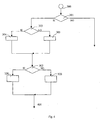
- FIGS 3, 4 and 5 illustrate, by way of example, the flowcharts corresponding to the method for controlling the operating functions of a cycle control implemented in the electronic control system 2.
- Figure 3 illustrates the part of procedure corresponding to the display unit 21.
- the choice step 201 identifies the operation of requesting whether the user wishes to enter programming mode.
- control goes to a set of choice steps from 202 to 207, which are implemented in conditioned sequence and which, if the answer "YES” is given (whatever the step considered between 202 and 207), lead to performing a step 220 for sending the request to the power unit 23.
- step 202 corresponds to the request as to whether the user wishes to proceed to a step for resetting the actuator.
- step 202 the control passes to a choice step 203, where the user is asked whether he wishes to exit the zero-setting step.
- step 203 the control passes to step 204, which asks the user whether he wishes to proceed to a compensation step.
- step 204 the control passes to step 205, where the user is asked whether he wishes to exit from the compensation step.
- step 205 the control passes to step 206, where the user is asked whether the manual mode of operation is to be set.
- step 206 the control passes to step 207, where the user is asked whether the automatic mode of operation is to be set.
- step 207 the control passes to end-of-procedure.
- Figure 4 illustrates the part of procedure corresponding to the control unit 22.
- a choice step 301 there is executed the operation asking whether a command is present at input, i.e., at the inputs 28 and 29, as a result of operation of the controls 18 and 19.
- control passes to a choice step 303, which evaluates whether the display unit 21 is present, i.e., connected to the control unit 22.
- control passes to a choice step 302, which evaluates whether the command is directed to the gear shift or the derailleur.
- step 320 for sending the corresponding request to the power unit 23.
- request comprises information on the presence or not of the display unit 22 obtained via steps 304 and 305.
- Figure 5 illustrates the part of procedure corresponding to the power unit 23.
- a choice step 401 is executed, which involves the operation of evaluating whether a command is present at input, forwarded by the steps of blocks 220 and 320.
- control passes to a choice step 405, which evaluates whether the display unit 21 is present, i.e., connected to the control unit 22, in particular on the basis of the request coming from blocks 320.
- control passes to a choice step 402, which evaluates whether the command detected at input requests execution of a step for zero-setting of an actuator.
- control passes to a block designated by 406, in which the operation of displacement of the actuator is executed as long as the command is present at input to block 401.
- control passes to a block 403, which evaluates whether the command requests execution of a step for compensation of the position of an actuator.
- control passes to a block designated by 407, in which the operation of compensation of the actuator is executed as long as the command is present at input to block 401.
- control passes to a choice step 404, which evaluates whether the command is of manual or automatic type.
- the control passes to a choice step 412, which evaluates whether the command detected at input requests execution of a step corresponding to the choice of a operation mode or setting of a parameter.
- control passes to a block, designated by 414, in which the values corresponding to the last parameter values already stored are re-loaded, said values being regarded in any case as reliable as compared to the uncertain state of the values that would appear upon removal of the display unit 21 during a procedure of choice of parameters.
- a block 415 there is performed the operation of resetting the operating mode.
- a block 416 there is set the request for normal procedure, which is sent to the corresponding choice step 404.
- control passes to the choice step 404.
- connection line 105 is interrupted and the control unit 22 can no longer receive commands from the display unit 21; namely, it can no longer transfer the requests in blocks 220 from the display unit 21 to the power unit 23.
- the procedures corresponding to the control unit 22 and to the power unit 23 are, however, organized so as to maintain operative a set of basic locomotion functions, in particular the control of the gear shift and of the derailleur, so as to enable the controls even with the display unit 21 removed, so that, for instance, the commands that appear at the choice step 301, imparted by the push-buttons 18 and 19, are received from the control unit 22 and forwarded to the corresponding choice step 401 relating the power unit 23.
- the control system 2 therefore continues to operate only according to a basic or normal operating mode.
- the electronic control system proposed may advantageously be employed also in anomalous situations, such as those of malfunctioning, theft or loss of the display unit.
- the invention can be implemented in the form of a control system (initial installation or retrofit), which is able to control the operating functions of a cycle and which comprises at least one first unit and one second unit that are able to co-operate functionally with one another, with the first unit being configured for being selectively removable from the cycle.
- the second unit is then configured for implementing the set of basic locomotion functions of the cycle, guaranteeing performance thereof (even) in conditions of removal of the first unit.
- the invention can also be realized by configuring, with an appropriate software, a programmable control system, which comprises at least one first unit and one second unit, which are able to co-operate functionally with one another, with the first unit selectively removable from the cycle, causing the second unit to be able to implement the basic locomotion functions of the cycle, ensuring performance thereof in conditions of removal of the first unit from the cycle.
- a programmable control system which comprises at least one first unit and one second unit, which are able to co-operate functionally with one another, with the first unit selectively removable from the cycle, causing the second unit to be able to implement the basic locomotion functions of the cycle, ensuring performance thereof in conditions of removal of the first unit from the cycle.
- the invention regards therefore also the aforesaid software, intended as computer-program product.
Landscapes
- Engineering & Computer Science (AREA)
- Chemical & Material Sciences (AREA)
- Combustion & Propulsion (AREA)
- Transportation (AREA)
- Mechanical Engineering (AREA)
- Control Of Transmission Device (AREA)
- Control Of Vehicle Engines Or Engines For Specific Uses (AREA)
- Steering Devices For Bicycles And Motorcycles (AREA)
- Mechanical Control Devices (AREA)
Priority Applications (5)
| Application Number | Priority Date | Filing Date | Title |
|---|---|---|---|
| EP03425181A EP1459975A1 (fr) | 2003-03-21 | 2003-03-21 | Système et méthode pour commander les fonctions operationelles d'une bicyclette |
| TW093106879A TW200500263A (en) | 2003-03-21 | 2004-03-15 | System and method for controlling the operating functions of a cycle, for example a competition bicycle, corresponding units and computer program product |
| JP2004073257A JP2004352221A (ja) | 2003-03-21 | 2004-03-15 | 自転車の動作機能を制御するためのシステム、方法、装置およびコンピュータプログラム製品 |
| CNA2004100301128A CN1550409A (zh) | 2003-03-21 | 2004-03-19 | 控制脚踏车的系统和方法,相应单元和计算机程序产品 |
| US10/806,569 US20040225380A1 (en) | 2003-03-21 | 2004-03-22 | System and method for controlling the operating functions of a cycle, corresponding units and computer program product |
Applications Claiming Priority (1)
| Application Number | Priority Date | Filing Date | Title |
|---|---|---|---|
| EP03425181A EP1459975A1 (fr) | 2003-03-21 | 2003-03-21 | Système et méthode pour commander les fonctions operationelles d'une bicyclette |
Publications (1)
| Publication Number | Publication Date |
|---|---|
| EP1459975A1 true EP1459975A1 (fr) | 2004-09-22 |
Family
ID=32799224
Family Applications (1)
| Application Number | Title | Priority Date | Filing Date |
|---|---|---|---|
| EP03425181A Withdrawn EP1459975A1 (fr) | 2003-03-21 | 2003-03-21 | Système et méthode pour commander les fonctions operationelles d'une bicyclette |
Country Status (5)
| Country | Link |
|---|---|
| US (1) | US20040225380A1 (fr) |
| EP (1) | EP1459975A1 (fr) |
| JP (1) | JP2004352221A (fr) |
| CN (1) | CN1550409A (fr) |
| TW (1) | TW200500263A (fr) |
Families Citing this family (4)
| Publication number | Priority date | Publication date | Assignee | Title |
|---|---|---|---|---|
| DE60315590T2 (de) * | 2003-03-21 | 2008-05-08 | Campagnolo S.R.L. | Einheiten zur Steuerung der Betriebsfunktionen eines Fahrrads |
| JP2005104286A (ja) * | 2003-09-30 | 2005-04-21 | Shimano Inc | 自転車用電子制御装置 |
| ITMI20071181A1 (it) * | 2007-06-12 | 2008-12-13 | Campagnolo Srl | Metodo di controllo elettronico di un cambio di bicicletta e sistema elettronico per bicicletta |
| KR101799956B1 (ko) | 2014-01-20 | 2017-11-21 | 가부시키가이샤 아이에이치아이 | 엔진 |
Citations (1)
| Publication number | Priority date | Publication date | Assignee | Title |
|---|---|---|---|---|
| US20010027495A1 (en) * | 2000-03-29 | 2001-10-04 | Valentino Campagnolo | Multiprocessor control system for cycles, for example for competition bicycles |
Family Cites Families (8)
| Publication number | Priority date | Publication date | Assignee | Title |
|---|---|---|---|---|
| US5059158A (en) * | 1990-05-08 | 1991-10-22 | E.B.T., Inc. | Electronic transmission control system for a bicycle |
| US6367833B1 (en) * | 2000-09-13 | 2002-04-09 | Shimano, Inc. | Automatic shifting control device for a bicycle |
| JP2003130197A (ja) * | 2001-10-22 | 2003-05-08 | Shimano Inc | 自転車用変速制御装置及び自転車用変速制御方法 |
| JP3654868B2 (ja) * | 2002-02-21 | 2005-06-02 | 株式会社シマノ | 自転車用変速制御装置及び自転車用変速制御方法 |
| JP2003252271A (ja) * | 2002-02-27 | 2003-09-10 | Shimano Inc | 自転車用表示装置 |
| US6781510B2 (en) * | 2002-07-24 | 2004-08-24 | Shimano, Inc. | Bicycle computer control arrangement and method |
| ATE521530T1 (de) * | 2002-12-06 | 2011-09-15 | Campagnolo Srl | Elektronisch, servobetätigte fahrradgangschaltung und zugehöriges verfahren |
| ATE353814T1 (de) * | 2002-12-06 | 2007-03-15 | Campagnolo Srl | Elektronisch, servobetätigte fahrradgangschaltung und zugehöriges verfahren |
-
2003
- 2003-03-21 EP EP03425181A patent/EP1459975A1/fr not_active Withdrawn
-
2004
- 2004-03-15 JP JP2004073257A patent/JP2004352221A/ja active Pending
- 2004-03-15 TW TW093106879A patent/TW200500263A/zh unknown
- 2004-03-19 CN CNA2004100301128A patent/CN1550409A/zh active Pending
- 2004-03-22 US US10/806,569 patent/US20040225380A1/en not_active Abandoned
Patent Citations (1)
| Publication number | Priority date | Publication date | Assignee | Title |
|---|---|---|---|---|
| US20010027495A1 (en) * | 2000-03-29 | 2001-10-04 | Valentino Campagnolo | Multiprocessor control system for cycles, for example for competition bicycles |
Also Published As
| Publication number | Publication date |
|---|---|
| TW200500263A (en) | 2005-01-01 |
| JP2004352221A (ja) | 2004-12-16 |
| US20040225380A1 (en) | 2004-11-11 |
| CN1550409A (zh) | 2004-12-01 |
Similar Documents
| Publication | Publication Date | Title |
|---|---|---|
| CN113212240B (zh) | 车辆控制装置、方法、存储介质和车辆 | |
| EP2949516B1 (fr) | Contrôleur de bloc d'alimentation pour véhicule | |
| EP1619375B1 (fr) | Dispositif pour commander un moteur électrique et procédé pour surveiller un fonctionnement défectueux d'un moteur électrique | |
| US20060175902A1 (en) | Method and apparatus for start control of a vehicle | |
| JP2008087534A (ja) | 車両用負荷制御システム | |
| US7923161B2 (en) | Fuel cell system | |
| CN104340120B (zh) | 车载负载控制系统 | |
| EP1459975A1 (fr) | Système et méthode pour commander les fonctions operationelles d'une bicyclette | |
| US11541930B2 (en) | Rotary electric machine control device | |
| US6970776B2 (en) | Communication error detecting method for bus communication network in vehicle | |
| JP2003026024A (ja) | 電動パワーステアリングの制御装置 | |
| US20060109090A1 (en) | Antitheft device | |
| US9474024B2 (en) | Mobile communication apparatus switching on and off state with distance from communicating external apparatus | |
| EP1460731B1 (fr) | Eléments pour controler les fonctions d'utilisation d'une bicyclette | |
| US8987945B2 (en) | Switch supervision device, control system and control method | |
| EP4001018A1 (fr) | Système d'alimentation électrique embarqué | |
| CN102695867B (zh) | 车辆启动控制装置 | |
| CN103201812A (zh) | 组合开关 | |
| JP3994570B2 (ja) | 集合電池の過放電防止装置 | |
| JP3895912B2 (ja) | 制御ユニット及び、多重通信システム | |
| EP3960523B1 (fr) | Engin de travail | |
| CN110723131A (zh) | 混动汽车的真空泵控制方法、装置、系统及存储介质 | |
| JP7063312B2 (ja) | 電子制御装置 | |
| KR101155199B1 (ko) | 지역 내부 연결 네트워크 통신을 사용하는 차량용 선루프제어 시스템 및 방법 | |
| KR20220032750A (ko) | 조향 제어 장치 및 방법 |
Legal Events
| Date | Code | Title | Description |
|---|---|---|---|
| PUAI | Public reference made under article 153(3) epc to a published international application that has entered the european phase |
Free format text: ORIGINAL CODE: 0009012 |
|
| AK | Designated contracting states |
Kind code of ref document: A1 Designated state(s): AT BE BG CH CY CZ DE DK EE ES FI FR GB GR HU IE IT LI LU MC NL PT RO SE SI SK TR |
|
| AX | Request for extension of the european patent |
Extension state: AL LT LV MK |
|
| 17P | Request for examination filed |
Effective date: 20050314 |
|
| AKX | Designation fees paid |
Designated state(s): AT BE BG CH CY CZ DE DK EE ES FI FR GB GR HU IE IT LI LU MC NL PT RO SE SI SK TR |
|
| 17Q | First examination report despatched |
Effective date: 20081127 |
|
| STAA | Information on the status of an ep patent application or granted ep patent |
Free format text: STATUS: THE APPLICATION IS DEEMED TO BE WITHDRAWN |
|
| 18D | Application deemed to be withdrawn |
Effective date: 20091030 |