EP1459962A2 - Servolenkung und Nullpunktbestimmung für einen Drehmomentsensor in einer Servolenkung - Google Patents
Servolenkung und Nullpunktbestimmung für einen Drehmomentsensor in einer Servolenkung Download PDFInfo
- Publication number
- EP1459962A2 EP1459962A2 EP04003402A EP04003402A EP1459962A2 EP 1459962 A2 EP1459962 A2 EP 1459962A2 EP 04003402 A EP04003402 A EP 04003402A EP 04003402 A EP04003402 A EP 04003402A EP 1459962 A2 EP1459962 A2 EP 1459962A2
- Authority
- EP
- European Patent Office
- Prior art keywords
- torque
- steering
- power
- handle
- initial
- Prior art date
- Legal status (The legal status is an assumption and is not a legal conclusion. Google has not performed a legal analysis and makes no representation as to the accuracy of the status listed.)
- Withdrawn
Links
- 238000001514 detection method Methods 0.000 claims abstract description 62
- 230000003247 decreasing effect Effects 0.000 claims abstract description 58
- 230000007935 neutral effect Effects 0.000 claims abstract description 29
- 230000010355 oscillation Effects 0.000 claims abstract description 19
- 238000003860 storage Methods 0.000 claims description 15
- 230000033001 locomotion Effects 0.000 claims description 11
- 230000005540 biological transmission Effects 0.000 claims description 7
- 238000004904 shortening Methods 0.000 claims description 6
- 230000004044 response Effects 0.000 claims description 5
- 230000009471 action Effects 0.000 claims description 2
- 230000003252 repetitive effect Effects 0.000 abstract description 4
- 238000012545 processing Methods 0.000 description 23
- 238000004088 simulation Methods 0.000 description 21
- 230000008030 elimination Effects 0.000 description 19
- 238000003379 elimination reaction Methods 0.000 description 18
- 238000013500 data storage Methods 0.000 description 16
- 238000004519 manufacturing process Methods 0.000 description 10
- 238000010276 construction Methods 0.000 description 9
- 230000004048 modification Effects 0.000 description 8
- 238000012986 modification Methods 0.000 description 8
- 230000007423 decrease Effects 0.000 description 5
- 230000003292 diminished effect Effects 0.000 description 5
- 238000000034 method Methods 0.000 description 5
- 230000015654 memory Effects 0.000 description 4
- 230000003467 diminishing effect Effects 0.000 description 3
- 230000006870 function Effects 0.000 description 3
- 238000007689 inspection Methods 0.000 description 3
- 230000007246 mechanism Effects 0.000 description 3
- 230000008569 process Effects 0.000 description 3
- 230000008439 repair process Effects 0.000 description 3
- 238000004891 communication Methods 0.000 description 2
- 238000012790 confirmation Methods 0.000 description 2
- 230000008901 benefit Effects 0.000 description 1
- 239000012530 fluid Substances 0.000 description 1
- 238000010348 incorporation Methods 0.000 description 1
- 230000003534 oscillatory effect Effects 0.000 description 1
- 230000009467 reduction Effects 0.000 description 1
- 230000001846 repelling effect Effects 0.000 description 1
- 230000007704 transition Effects 0.000 description 1
Images






Classifications
-
- B—PERFORMING OPERATIONS; TRANSPORTING
- B62—LAND VEHICLES FOR TRAVELLING OTHERWISE THAN ON RAILS
- B62D—MOTOR VEHICLES; TRAILERS
- B62D6/00—Arrangements for automatically controlling steering depending on driving conditions sensed and responded to, e.g. control circuits
- B62D6/08—Arrangements for automatically controlling steering depending on driving conditions sensed and responded to, e.g. control circuits responsive only to driver input torque
- B62D6/10—Arrangements for automatically controlling steering depending on driving conditions sensed and responded to, e.g. control circuits responsive only to driver input torque characterised by means for sensing or determining torque
-
- G—PHYSICS
- G01—MEASURING; TESTING
- G01L—MEASURING FORCE, STRESS, TORQUE, WORK, MECHANICAL POWER, MECHANICAL EFFICIENCY, OR FLUID PRESSURE
- G01L5/00—Apparatus for, or methods of, measuring force, work, mechanical power, or torque, specially adapted for specific purposes
- G01L5/22—Apparatus for, or methods of, measuring force, work, mechanical power, or torque, specially adapted for specific purposes for measuring the force applied to control members, e.g. control members of vehicles, triggers
- G01L5/221—Apparatus for, or methods of, measuring force, work, mechanical power, or torque, specially adapted for specific purposes for measuring the force applied to control members, e.g. control members of vehicles, triggers to steering wheels, e.g. for power assisted steering
Definitions
- the present invention relates to a power steering device for vehicles such as automobiles or motorcars, and more particularly, to a power steering device capable of detecting an origin or zero-point torque of a torque sensor incorporated therein. It also relates to a zero-point setting device for a torque sensor incorporated in such a power steering device.
- power assist mechanisms for steering manipulation have been widespread as steering devices of vehicles and particularly, as those of automobiles or motorcars. For this reason, these days such power steering devices are installed on almost all the motorcars manufactured in factories. Therefore, it is often the case that the repair or replacement of such power steering devices is done at car dealers regardless of whether new cars or used cars.
- power steering devices are of the type that the steering torque applied to a handle shaft through a steering handle is detected by torque detection means and that a drive power corresponding to the detected torque is generated by assist power generating means such as an electric motor and is transmitted to steerable wheels, as exemplified in Japanese unexamined, published patent applications No. 2000-168597 and No. 2001-341656.
- the steering handle In the initial setting of steering control of the power steering device, the steering handle is stationarily held at a neutral position in the steering direction with the applied torque having been removed, in which state the torque detection means then detects and indicates an initial torque.
- This initial torque includes an origin torque corresponding to the assembling error in manufacturing and a residual torque generated due to the imperfect returning of the steering handle.
- the origin torque cannot be eliminated unless the torque detection device is disassembled and adjusted.
- the origin torque exists as a peculiar value (i.e., constant value) to the device to be compensated easily. Therefore, the origin torque is relatively small in the influence upon the,regular steering control insofar as the value thereof is specified at the time of the initial setting.
- the residual torque is liable to cause wrong steering control when the imperfect returning of the steering handle is corrected upon shifting to the regular steering control state. And, the influenced by the residual torque is liable to be more exerted on a power steering device of rack assist type than on that of column assist type.
- the assist power generating means and the torque detection means are provided close to the steering shaft (rack shaft) as shown in the aforementioned Japanese '597 application and hence that the distance between the steering handle and the torque detection means becomes longer than that in the column assist type power steering device wherein the assist power generating means and the torque detection means are provided on a steering column, as shown in the aforementioned Japanese '656 application.
- a power steering device of the type wherein a steering torque applied to a handle shaft through a steering handle is detected by torque detection means and wherein a drive power corresponding to the steering torque is applied from assist power generating means to steerable wheels.
- the power steering device comprises residual torque decreasing command means for operating the assist power generating means to turn the steering handle a minute rotational angle in positive and negative-going directions about a handle axis after the steering handle is once held stationarily at a neutral position in the steering direction so that a residual torque remaining as hysteresis between the steering handle and the torque detection means can be decreased.
- the assist power generating means such as, e.g., electric motor which is provided on the power steering device for steering control is utilized to decrease (or eliminate) the residual torque.
- the operation for decreasing the residual torque can be carried out precisely in a short period of time without introducing a large-scale facility therefor.
- the rate at which the residual torque remains in the detected value of the initial torque becomes small. Accordingly, when the power steering device is then brought into the regular steering control state and is controlled based on the initial torque from which the residual torque has been eliminated, it can be prevented from being wrong operated, so that the stability in controlled can be enhanced.
- a power steering device is of the type wherein a steering torque applied to a handle shaft through a steering handle is detected by torque detection means which is provided with a torsion bar and a pair of angle detection sensors arranged apart from each other in the axial direction of the torsion bar and wherein a drive power corresponding to the steering torque is applied from assist power generating means to steerable wheels.
- the power steering device comprises residual torque decreasing command means for operating the assist power generating means to turn the steering handle a minute rotational angle in positive and negative-going directions about a handle axis after the steering handle is once held stationarily at a neutral position in the steering direction, so that a residual torque remaining as hysteresis between the steering handle and the torque detection means can be decreased.
- the power steering device further comprises initial torque detection command means for making the assist power generating means terminate the minute angle rotational motion and for issuing a command to detect by the torque detection means an initial torque which is caused primarily by the difference in origin position between the pair of angle detection sensors with the residual torque being diminished.
- decreasing (or eliminating) the residual torque from the output of the torque detection means can be performed precisely in a short period of time. Therefore, an origin torque of the torque detection means which is essential in manufacturing the power steering device can be detected as precisely and quickly as possible with the residual torque being decreased (or, eliminated) to the utmost.
- a zero-point setting device for a torque sensor in a power steering device having a torque sensor provided in a steering power transmission system from a steering handle to steerable wheels of a vehicle for detecting a steering torque and steering control means for controlling a steering drive device to apply a steering power to said steerable wheels.
- the zero-point setting device comprises steerable wheel oscillating means operable prior to detecting a zero-point torque error of the torque sensor in the state that the steerable wheels are held at a reference position such as a neutral position or the like with the steering handle being not given any steering torque applied thereto, for oscillating the steerable wheels within a minute angular range in the steering direction so that the amplitude of the oscillation is gradually decreased to the termination of the oscillation.
- the zero-point setting device further comprises zero-point torque detection means for detecting an output of the torque sensor as the zero-point torque error at or around at the termination of the oscillation, and storage means for storing the zero-point torque error in a storage area of the steering control means so that in the later actual operation of the steering drive device, the same is controlled by the steering control means based on a compensated torque which is calculated from both of an output of the torque sensor and the zero-point torque error stored in the storage means.
- the operation for decreasing (or, eliminating) the residual torque remaining in the steering power transmission system can be performed precisely in a short period of time. Therefore, in the process of detecting an initial torque for the initial setting of the power steering device of the type having the torque detection means which is composed of a torsion bar and a pair of angle detection sensors, an origin torque of the torque detection means which is essential in manufacturing the power steering device can be detected as precisely and quickly as possible with the residual torque being decreased (or, eliminated) to the utmost.
- FIG. 1 schematically shows the general construction of an electric power steering device as one example of the power steering devices to which the present invention is applied.
- vehicle used herein means an automobile or motorcar
- the electric power steering device 100 (hereinafter referred to as "power steering device") has a steering handle 1 connected to a handle shaft 2, and a pinion shaft 3 connected to the handle shaft 2 through a torsion bar 11 is provided with a pinion 4, which is in meshing engagement with rack teeth 5a of a steering shaft 5.
- a D.C. assist motor 20 as assist power generating means is assembled coaxially through a ball screw mechanism (not shown).
- the power steering device 100 is constructed as of the rack assist type that the drive power of the assist motor 20 assists the reciprocative movement of the steering shaft 5 given by the steering handle 1.
- a torque sensor 10 serving as torque detection means is provided between the handle shaft 2 and the pinion shaft 3.
- the torque sensor 10 is composed of the torsion bar 11 and a pair of resolvers 12, 12 installed spaced apart from each other in the axial direction of the torsion bar 11.
- the torsion bar 11 interconnects the facing ends of the handle shaft 2 and the pinion shaft 3, and the resolvers 12, 12 serve as angle detecting sensors.
- the rotational angular position of the assist motor 20 is detected by a motor angular position detecting section 21 including a rotary encoder or the like.
- the assist motor 20 driven through a motor driver 22 generates a drive power (rotational power) corresponding to the steering torque detected by the torque sensor 10.
- a control unit or section 30 includes a CPU (Central Processing Unit) 31, a RAM (Random Access Memory) 32, a ROM (Read-Only Memory) 33, an input/output interface 34 and the like, which are connected via a bus 35 for data transmission and receiving thereby to be constituted as a microcomputer.
- the ROM 33 has a program storage area 33a and a data storage area 33b.
- the program storage area 33a has stored therein a steering control program for controlling the foregoing steering angle and the steering torque, an initial setting program referred to later, and the like.
- the data storage area 33b has stored therein an initial torque referred to later and thus, performs the function as initial torque storage means.
- the CPU 31 performs many functions such as residual torque decreasing command means, initial torque detection command means, initial torque storage command means and the like which will be described later.
- the initial setting program stored in the program storage area 33a is designed for detecting an initial torque to store the same in the data storage area 33b after decreasing (eliminating) a residual torque from the initial torque and makes it possible to use the detected initial torque as a compensation value for the steering torque in the steering control program.
- an initial setting program is prepared to be started upon receipt of a particular trigger signal transmitted from a small-sized tester (i.e., a portable terminal device) 40 which is temporally brought into connection with the input/output interface 34. Therefore, it is easy for dealer mechanics to perform the initial setting (i.e., detecting and storing the initial torque) of each power steering device to be repaired or adjusted in the dealer service site or repair shop.
- an external microcomputer which is equipped in a manufacturing plant or the like, in which case the initial setting program may be downloaded from the microcomputer by way of a communication line, a suitable storage medium or the like to the steering control section 30, and the initial setting program may be started upon receipt of a trigger signal from the external microcomputer.
- the CPU 31 When having the trigger signal input thereto, the CPU 31 reads the initial setting program from the program storage area 33a of the ROM 33 and executes at least the following processing of the read-out program in the order of steps described below. That is, the CPU 31:
- the data storage area 33b may be constituted by an EPROM (Erasable Programmable Read-Only Memory) so that the initial torque can be written thereinto each time the initial setting is done.
- EPROM Erasable Programmable Read-Only Memory
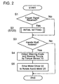
- FIG. 2 shows the general configuration of the steering control program, in accordance with which the CPU 31 watches for a trigger signal from the external device, and upon receipt of the trigger signal (YES at step S1), proceeds to the initial setting program S2 shown in Figure 3.
- the CPU 31 checks whether or not, the handle shaft 2 has begun to rotate with the steering handle 1, from the variation in the angular difference between the pair of resolvers 12, 12 (step S3).
- the CPU 31 detects the steering angle of the handle shaft 2 and the steering torque by the torque sensor 10 (step S4). Then, the CPU 31 operates the motor driver 22 and drives the assist motor 20.
- the handle shaft 2 is not rotated (NO at step S3), the CPU 31 terminates the program to execute nothing.
- FIG 3 shows the details of the initial setting program S2.
- the CPU 31 at step S21 instructs the worker to rotate and hold the steering handle 1 stationarily at the neutral position in the steering direction, and thus, the worker does so in response thereto.
- the CPU 31 at step S22 sets a simulation torque value (Tk) (e.g., +2N ⁇ m) to be applied to the steering handle 1, and at step S23, compares a target rotational angle ( ⁇ m) to which the steering handle 1 is assumed to be rotated minutely based on the simulation torque value (Tk), with the absolute value of an actual rotational angle ( ⁇ z) being detected by the torque sensor 10.
- Tk simulation torque value
- step S27 to apply to the assist motor 20 an electric current corresponding in current value and application time period to the simulation torque value (Tk) (i.e., the target rotational angle ⁇ m).
- Tk simulation torque value
- an electric current corresponding to +2N • m is applied to the assist motor 20 for 60 milliseconds as referred to Figure 4(A).
- step S23 Since the target rotational angle ( ⁇ m) is larger than zero (0) first at step S28 (i.e., NO at step S28), return is made to step S23 to again compare the target rotational angle ( ⁇ m) with the absolute value of the actual rotational angle ( ⁇ z).
- > ⁇ m i.e., YES at step S23
- the CPU 31 reverses the simulation torque value (Tk) at step S24 and decreases or decrements the same at step S25 (e.g., to -1.5 N • m) to diminish the target rotational angle ( ⁇ m) in correspondence thereto at step S26).
- the CPU 31 at step S27 applies to the assist motor 20 an electric current corresponding in current value and application time period to the simulation torque value (Tk) (i.e., a target rotational angle ( ⁇ m)) which is set again through steps S24 and S25.
- Tk simulation torque value
- ⁇ m target rotational angle
- an electric current corresponding to -1.5N • m is applied to the assist motor 20 for 60 milliseconds, as referred to Figure 4(a).
- steps S24 to S27 there may be executed at least one of the processing for decreasing the absolute value of the electric current flown through the assist motor 20 and the processing for shortening the time period for which the electric current is applied to the assist motor 20.
- both of the aforementioned two processing are executed, whereby the absolute value of the torque value which causes the steering handle 1 to turn repetitively in positive and negative going directions is made smaller and smaller as time goes by. It results accordingly that the steering handle 1 is rotated by the assist motor 20 periodically in the positive and negative-going directions in response to the predetermined torque value (i.e., the simulation torque value (Tk)).
- Tk simulation torque value
- the assist motor 20 While the torque sensor 10 detects the torque applied by the assist motor 20 during these steps of processing, the assist motor 20 is controlled to drivingly rotate the steering handle 1 a minute angle based on the simulation torque value (Tk) which has been set in advance in accordance with the initial setting program independently of the torque value detected by the torque sensor 10.
- Tk simulation torque value
- the minute rotational motion of the steering handle 1 by the assist motor 20 is terminated under the judgment that the residual torque should have been decreased sufficiently (i.e., approximately zero), and then an initial torque T0 (e.g., +0.2 N • m) is detected by the torque sensor 10 at step S29.
- the CPU 31 at step S30 stores the detected initial torque T0 as a compensation value in steering torque control, in the data storage area 33b of the steering control section 30.
- the program may be arranged to make the worker push a confirmation switch when the worker confirms that the steering handle 1 has been held stationarily at the neutral position.
- the assist motor 20 is operated to rotate the steering handle 1 with the predetermined torque value repetitively in the positive and negative-going directions while gradually decreasing or decrementing the absolute value of the torque value in connection with the time passage. Therefore, it becomes realized to restrain the occurrence of the imperfect returning phenomenon (i.e., hysteresis phenomenon) of the steering handle 1 thereby to decrease (or, eliminate) the residual torque within a short period of time to the extent that the same no longer obstructs the steering control operation.
- the drive torque of a DC motor is in proportion to the value of an electric current flown therethrough. Therefore, in the processing for diminishing the residual torque, if the value of an electric current flown through the assist motor 20 is taken as an objective or target to be controlled, it becomes possible to precisely control the torque value of the assist motor (DC motor) 20.
- means for decreasing the rotational power (torque) which is applied by the assist motor 20 to the steering handle 1 can be selected from the followings:
- the followings are the points to which cares are to be taken in executing the initial setting program stored in the steering control section 30 at inspection processes of manufacturing sites, factory floors or the like or at service sites of car dealers or the like.
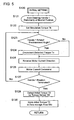
- Figure 5 shows a flow chart modified from that shown in Figure 3, and Figure 6 is an explanatory view showing the state of a processing for decreasing the residual torque in accordance with the processing shown in Figure 5.
- Steps S23 through S28 in Figure 3 for decrementing the residual torque are altered and shown as steps S123 through S127 in Figure 5.
- the assist motor 20 is rotated reversibly so that the steering handle 1 is given the rotational force in the negative or positive-going direction in dependence upon the plus or minus of a torque value detected by the torque sensor 10.
- step S122 is executed to set a simulation torque value (Tk) (e.g., +2N • m) to be applied to the steering handle 1 in the same manner as was done in the processing shown in Figure 3. That is, the steering handle 1 in the first rotation is rotated at a predetermined torque value (i.e., the simulation torque value (Tk)) and in a predetermined rotational direction. Whether or not, the steering handle 1 has been turned a predetermined angle is confirmed at step S123 by reference to the torque value detected by the torque sensor 10. If the rotation through the predetermined angle has been attained (i.e., YES at step S123), the steering handle 1 is then rotated to cancel the torque value (Ts) so that the residual torque can be decreased (or, eliminated).
- Tk simulation torque value
- a smaller torque than the detected torque value (Ts) is set at step S124 and the direction of the electric current flown through the assist motor 20 is reversed at step S125, after which an electric current corresponding to the smaller torque is applied to the assist motor 20 to flow in the reversed direction at step S126.
- step S123 for repeating the residual torque decreasing (or, elimination) processing while gradually diminishing the detected torque value (Ts) and while switching the turning direction form one direction to the other direction and vice versa.
- the detected torque value (Ts) is gradually made smaller (i.e., smaller and smaller), so that it no longer becomes to have a drive power (rotational force) to turn the steering handle 1.
- step S127 i.e., YES at step S127
- step S1 i.e., YES at step S127
- an initial torque (T0) is detected by the torque sensor 10 at step S129, and the detected initial torque (T0) is stored in the data storage area 33b at step S130.
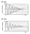
- the assist motor 20 in this particular modification periodically repeats the rotations in the positive and negative-going directions as depicted in Figures 6(a) and 6(b), so that the steering handle 1 can be given a rotational power in the negative or positive-going direction (i.e., the rotational power to cancel the detected torque power) in dependence on the plus or minus sign of the torque value detected by the torque sensor 10.
- the residual torque can be diminished (or, eliminated) only through a relatively simplified control of providing the assist motor 20 with a rotational power which can cancel the torque value detected by the torque sensor 10.
- means for decreasing the rotational power (torque) which is applied by the assist motor 20 to the steering handle 1 can be selected, in the same manner as done in the embodiment shown in Figures 3, 4(a) and 4(b), from the followings:
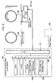
- the power steering device 100 in the second embodiment basically takes the same construction as the foregoing first embodiment shown in Figure 1 except for the following additional construction. That is, in the second embodiment shown in Figure 7, the assist motor 20 driven by the motor driver 22 generates a drive power which corresponds to the applied torque to the torsion bar 11 detected by the torque sensor 10.
- the vehicle with the power steering device 100 is parked or placed on a flat floor.
- a pair of turntables 56, 56 are placed so that mounting surfaces thereof for the steerable wheels 6, 6 lie at the same level as the floor.
- the turntables 56, 56 are moved up and down in dependence on the height of the steerable wheels 6, 6, so that the same load as exerted when the vehicle is grounded on the floor is applied on each of the turntables 6, 6.
- the steering control section 30 basically takes the same construction as described in connection with the foregoing first embodiment.
- a residual toque elimination control section 50 is further provided, which is responsive to signals from the resolvers 12, 12 for controlling the turntables 56, 56, as described later in detail.
- the CPU 31 of the steering control section 30 reads an initial setting program from the program storage area 33a of the ROM 33 and executes at least the following processing of the read-out program in the order of steps described below. That is, the CPU 31:
- the data storage area 33b in this second embodiment may be constituted by an E 2 PROM (Electrically Erasable Programmable Read-Only Memory) so that the initial torque can be written thereinto each time the initial setting is done.
- E 2 PROM Electrically Erasable Programmable Read-Only Memory
- FIG 9 shows the general configuration of the steering control program.
- the CPU 31 watches for the trigger signal from the external device, and upon receipt of the trigger signal (YES at step S201), detects an initial toque by the torque sensor 10 to store the initial torque in the data storage area 33b at step S202. In the absence of the trigger signal (NO at step S201), the CPU 31 checks whether or not, a torque has been applied on the torsion bar 11, from the variation in the angular difference between the pair of resolvers 12, 12 (step S203).
- the CPU 31 detects the applied torque by the torque sensor 10 (step S204). Then, the CPU 31 operates the motor driver 22 and drives the assist motor 20 with a drive power corresponding to a net torque which is obtained by compensating the applied torque detected by the torque sensor 10 for the initial torque stored in the data storage area 33b (step S205). On the other hand, when there occurred no angular difference on the resolvers 12, 12 (NO at step S203), the CPU 31 terminates the program to execute nothing.
- the residual toque elimination control section 50 is composed of a CPU 51, a RAM 52, a ROM 53, an input/output interface 54 or the like, which are connected via a bus 55 for data transmission and receiving thereby to constitute a microcomputer.
- the ROM 53 includes a program storage area 53a and a data storage area 53b.
- the program storage area 53a has stored a residual toque elimination control program therein, while the data storage area 53b is to store an simulation torque, as referred to later.
- the residual toque elimination control section 50 is connected to the torque sensor 10 and a motor 57 via the input/output interface 54.
- the motor 57 is able to rotate turntables 56, 56 within a minute angular range through a reduction mechanism 58.
- a reduction mechanism 58 In this particular embodiment shown in Figure 8, only the turntable 56 at the right side in the vehicle traveling direction is rotatable by the motor 57, while the other turntable 56 at the left side in the vehicle traveling direction is left rotatable freely.
- both of the turntables 56, 56 at the right and left sides are rotatable within the minute angular range.
- a small-sized tester i.e., a portable terminal device 40 is temporally or permanently brought into connection with the input/output interface 54, and the residual torque elimination control program is prepared to be started upon receipt of the particular trigger signal transmitted from the small-sized tester 40.
- an external microcomputer which is equipped in a manufacturing plant or the like, in which case the residual torque elimination control program may be downloaded from the microcomputer by way of a communication line, a suitable storage medium or the like to the residual torque elimination control section 50, and the residual torque elimination control program may be started upon receipt of the trigger signal from the external microcomputer.
- the CPU 51 When having the trigger signal input thereto, the CPU 51 reads the residual torque elimination control program from the program storage area 53a of the ROM 53 and executes the residual torque elimination control program. That is, in the state that the steering handle 1 is held stationarily at the neutral position in the steering direction, the CPU 51 operates the motor 57 to rotate the turntable 56 a minute angle, so that a residual torque remaining as hysteresis between the steering handle 1 and the torque sensor 10 can be decreased or eliminated.
- the data storage area 33b may be constituted by an E 2 PROM which is capable of performing electrical writing-in and electrical erasion so that a simulation torque suitable to the construction of the power steering device 100 can be written thereinto.
- the CPU 51 at step S221 instructs the worker to rotate and hold the steering handle 1 stationarily at the neutral position in the steering direction, and thus, the worker does so in response thereto.
- the CPU 51 at step S222 sets a simulation torque value (Tk) (e.g., +2N • m) to be applied to the turntable 56, and at step S223, compares a target rotational angle ( ⁇ m) through which the turntable 56 is assumed to be rotated minutely based on the simulation torque value (Tk), with the absolute value of an actual rotational angle ( ⁇ z) being detected by the torque sensor 10.
- Tk simulation torque value
- ⁇ m target rotational angle
- step S227 to apply to the motor 57 an electric current corresponding in current value and application time period to the simulation torque value (Tk) (i.e., the target rotational angle ⁇ m).
- Tk simulation torque value
- an electric current corresponding to the torque of +2N • m is applied to the motor 57 for 60 milliseconds as referred to Figure 4(a).
- step S228 Since the target rotational angle ( ⁇ m) is larger than zero (0) first at step S228 (i.e., NO at step S228), return is made to step S223 to again compare the target rotational angle ( ⁇ m) with the absolute value of the actual rotational angle ( ⁇ z). Then, there comes
- Tk simulation torque value
- the CPU 51 at step S227 applies to the motor 57 an electric current corresponding in current value and application time period to the decreased simulation torque value (Tk) (i.e., a target rotational angle ⁇ m) which has been set again through steps S224 to S226.
- Tk simulation torque value
- an electric current corresponding to -1.5N m is applied to the motor 57 for 60 milliseconds, as referred to Figure 4(a).
- steps S224 to S227 there is executed at least one of the processing for decreasing or decrementing the absolute value of the electric current flown through the motor 57 and the processing for shortening the time period for which the electric current is applied to the motor 57.
- both of the aforementioned two processing are executed, whereby the absolute value of the torque value which causes the turntable 56 to turn repetitively in positive and negative going directions is made smaller and smaller as time goes by. It results accordingly that the turntable 56 is turned by the motor 57 periodically in the positive and negative-going directions with the predetermined torque value (i.e., the simulation torque value (Tk)) being kept.
- the predetermined torque value i.e., the simulation torque value (Tk)
- the motor 57 While the torque sensor 10 continues to detect the torque applied by the motor 57 during these steps of processing, the motor 57 is controlled to drivingly turn the turntable 56 a minute angle at the simulation torque value (Tk) which has been set in advance in accordance with the residual torque elimination program independently of the torque value detected by the torque sensor 10. Thereafter, when the target rotational angle ( ⁇ m) is judged at step S228 to have become zero or smaller than zero (i.e., YES at step S228), the minute turning motion by the motor 57 is terminated (stopped) under the judgment that the residual torque has been diminished sufficiently (i.e., approximately to zero).
- the transitions of the target rotational angle ⁇ m and the actual rotational angle ( ⁇ z) are represented as shown in Figure 4(b).
- the trigger signal is transmitted from the tester 40 to the steering control section 30.
- the CPU 31 of the steering control section 30 executes the initial setting program to detect an initial torque (T0), e.g., +0.2 N ⁇ m) by the torque sensor 10 at step S229. Then, the CPU 31 at step S230 stores the detected initial torque (T0) as a compensation value in steering torque control, in the data storage area 33b of the steering control section 30.
- the program may be arranged to make the worker push a confirmation switch when the worker confirms that the steering handle 1 has been held stationarily at the neutral position.
- the steerable wheels 6, 6 are turned by the turntables 56, 56 with the torque of the predetermined value repetitively in the positive and negative-going directions while decrementing the absolute value of the torque value as time passes.
- the drive torque of a DC motor is in proportion to the value of an electric current flowing therethrough. Therefore, in the processing for decreasing the residual torque, if the value of an electric current flowing through the motor 57 is taken as an objective or target to be controlled, it becomes possible to precisely control the torque value of the motor (DC motor) 57.
- means for decreasing the rotational power (torque) applied by the motor 57 to the turntable 56 can be selected from the followings:
- the turntable 6 is turned by the motor 57 in the aforementioned residual torque elimination control, it may be oscillated by a solenoid substituting for the motor 57, or it may be oscillated by utilizing magnetic attraction and repelling forces in the combination of an electromagnet and a permanent magnet.
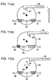
- Figures 11(a) to 11(c) show the turntable 56 in this modification as viewed from the bottom thereof.
- the connecting portion 62 of springs 60, 61 connected in series is secured to the turntable 56, and respective opposite ends of these springs 60, 61 are secured to those portions outside the turntable 56 with each of these springs 60, 61 extending perpendicularly to the direction in which the vehicle travels.
- the springs 60, 61 act as elastic support means for applying two urging forces which are opposite in direction to urge but equal to each other in magnitude, to the turntable 56 in the turn direction of the same so that the turntable 56 is held at its neutral position but allowed to turn against the urging forces of the springs 60, 61.
- a protrusion 64 is provided on the turntable 56 at a portion opposite to the connecting portion 62 with respect to a rotational center 63 of the turntable 56.
- a shaft 59 of an L-letter shape is further provided to draw the protrusion 64 toward the left, as viewed from the top of the turntable 56, of the direction in which the vehicle travels.
- the shaft 59 operates as oscillation starting means for turning the turntable 56 to a predetermined angular position shown in Figure 11(b) within the minute angular range in one direction against one of the springs 60, 61 and then for releasing the turntable 56 when the predetermined angular position is reached, thereby to enable the turntable 56 to oscillate in the positive and negative-going directions until the oscillation is gradually decreased to zero due to the natural decremental action of the springs 60, 61.
- the protrusion 64 is also drawn in the same direction as the shaft 50 is drawn.
- the shaft 59 is drawn to the predetermined position shown in Figure 11(b)
- the protrusion 64 is disengaged from the shaft 59.
- the springs 60, 61 oscillate by their memories while gradually diminishing the amplitudes of their oscillations, and so does the turntable 56.
- the steerable wheel 6 placed thereon oscillates thereby to eliminate the residual torque.
- the other steerable wheel 6, together with the other turn table 56 also oscillates because the two steerable wheels 6, 6 are connected to each other through the steering linkage.
- the springs 60, 61 in this modification there are employed those of the characteristic capable of providing the simulation torque as shown in Figure 4(a). Further, no particular restriction is imposed on the means for drawing the shaft 59 as long as it is controllable like the combination of a motor and gears, like a solenoid or like a fluid cylinder or so forth. Furthermore, in place of the shaft 59, there may be used an arrangement in which a cam to contact with the protrusion 64 is provided with a rotational shaft being located outside the turntable 56. No particular restrictions are imposed on the mounting positions for the springs 60, 61, the shaft 59 and the protrusion 64 as long as they are arranged to be able to eliminate the residual torque.
- the trigger signal is transmitted from the small-sized tester 40 to the steering control section 30, and the initial setting program is executed, whereby the initial torque (T0) is detected by the torque sensor 10 to be stored in the data storage area 33b.
- the followings are the points to which cares are to be taken in executing the residual torque elimination control program stored in the residual torque elimination control section 50 and the initial setting program stored in the steering control section 30 at inspection processes of manufacturing sites, factory floors or the like or at service sites of car dealers or the like.
- the present invention may be applicable to that of a column assist type.
- the present invention may be practiced in power steering devices of the type that the steering force is variable like, e.g., a speed responsive type, a rotational speed responsive type or the like.
- electric motor, hydraulic motor, hydraulic cylinder or the like may be used to constitute the assist power generating means.
- a modification may be made that after minute turn motions are carried out plural times with a predetermined simulation torque value (Tk) having been set (e.g., ⁇ 2 N • m), the simulation torque (Tk) may be made smaller (e.g., to ⁇ 1.5 N • m) prior to the subsequent minute turn motions at the plural times.
- Tk simulation torque value
- a power steering device is provided which is capable of detecting an initial torque of torque detection means precisely in a short period of time in the initial setting therefor.
- assist power generating means such as an electric motor for applying assist power to a handle shaft is used to rotate a steering handle within a minute rotational range in positive and negative-going directions from a neutral position in the steering direction.
- the rotation of the steering handle in this initial setting is performed so that the amplitude of the repetitive rotations in the positive and negative-going directions are decremented as time passes.
- an output of the torque detection means is detected as the initial torque with the steering handle being held stationarily at the neutral position.
- a zero-point detection device for a torque sensor in a power steering device having steerable wheel oscillating means which comprises turntables rotatable within a minute rotational range in positive and negative going directions and a turntable oscillating device for oscillating the turntables within the minute angular range in its steering direction by applying a drive power of a decremental pattern so that the amplitude of the oscillation is decreased gradually.
- steerable wheel oscillating means which comprises turntables rotatable within a minute rotational range in positive and negative going directions and a turntable oscillating device for oscillating the turntables within the minute angular range in its steering direction by applying a drive power of a decremental pattern so that the amplitude of the oscillation is decreased gradually.
Landscapes
- Engineering & Computer Science (AREA)
- Physics & Mathematics (AREA)
- General Physics & Mathematics (AREA)
- Chemical & Material Sciences (AREA)
- Combustion & Propulsion (AREA)
- Transportation (AREA)
- Mechanical Engineering (AREA)
- Steering Control In Accordance With Driving Conditions (AREA)
- Power Steering Mechanism (AREA)
Applications Claiming Priority (4)
| Application Number | Priority Date | Filing Date | Title |
|---|---|---|---|
| JP2003073041 | 2003-03-18 | ||
| JP2003073041A JP4143448B2 (ja) | 2003-03-18 | 2003-03-18 | パワーステアリング装置 |
| JP2003100807 | 2003-04-03 | ||
| JP2003100807A JP4058516B2 (ja) | 2003-04-03 | 2003-04-03 | 車両用操舵装置におけるトルクセンサのゼロ点設定装置 |
Publications (2)
| Publication Number | Publication Date |
|---|---|
| EP1459962A2 true EP1459962A2 (de) | 2004-09-22 |
| EP1459962A3 EP1459962A3 (de) | 2005-06-15 |
Family
ID=32829004
Family Applications (1)
| Application Number | Title | Priority Date | Filing Date |
|---|---|---|---|
| EP04003402A Withdrawn EP1459962A3 (de) | 2003-03-18 | 2004-02-16 | Servolenkung und Nullpunktbestimmung für einen Drehmomentsensor in einer Servolenkung |
Country Status (2)
| Country | Link |
|---|---|
| US (1) | US20040182626A1 (de) |
| EP (1) | EP1459962A3 (de) |
Cited By (1)
| Publication number | Priority date | Publication date | Assignee | Title |
|---|---|---|---|---|
| CN110319967A (zh) * | 2019-07-11 | 2019-10-11 | 吉林瑞铭机电设备有限公司 | 一种eps手柄力自动检测机 |
Families Citing this family (8)
| Publication number | Priority date | Publication date | Assignee | Title |
|---|---|---|---|---|
| FR2892086B1 (fr) * | 2005-10-19 | 2009-08-21 | Peugeot Citroen Automobiles Sa | Systeme d'aide a la manoeuvre pour un vehicule automobile. |
| ATE441567T1 (de) * | 2005-11-30 | 2009-09-15 | Svend Egenfeldt | Fernsteuersystem |
| US8660754B2 (en) * | 2007-08-17 | 2014-02-25 | Sauer-Danfoss Aps | Steer by wire control system |
| CN103808452B (zh) * | 2012-11-15 | 2016-09-14 | 台达电子工业股份有限公司 | 电动助力转向装置的零点调整方法及其调零装置 |
| DE102015200122B4 (de) * | 2015-01-08 | 2016-11-03 | Robert Bosch Gmbh | Verfahren und Vorrichtung zum Betreiben eines Kraftfahrzeugs mit einer Sicherheitseinrichtung zur Kompensation fehlerhafter Drehmomente |
| EP3330160B1 (de) * | 2015-07-31 | 2020-03-18 | Nissan Motor Co., Ltd. | Steer-by-wire-system und steuerungsverfahren für steer-by-wire-system |
| KR102341111B1 (ko) * | 2015-12-14 | 2021-12-21 | 현대모비스 주식회사 | 전동식 조향 장치 및 그 제어 방법 |
| CN114483013B (zh) * | 2021-12-30 | 2025-01-28 | 中国石油天然气集团有限公司 | 泥浆压力波信号调制装置及方法 |
Citations (3)
| Publication number | Priority date | Publication date | Assignee | Title |
|---|---|---|---|---|
| JP2000168597A (ja) | 1998-12-08 | 2000-06-20 | Toyota Motor Corp | 電動式パワーステアリング装置 |
| JP2001194251A (ja) | 2000-01-06 | 2001-07-19 | Tamagawa Seiki Co Ltd | パワーステアリング検出装置 |
| JP2001341656A (ja) | 2000-06-01 | 2001-12-11 | Toyoda Mach Works Ltd | 電動式パワーステアリング装置及びウォームギヤのバックラッシ調整装置 |
Family Cites Families (7)
| Publication number | Priority date | Publication date | Assignee | Title |
|---|---|---|---|---|
| DE2819394C2 (de) * | 1977-08-20 | 1985-01-17 | Laycock Engineering Ltd., Sheffield, Yorkshire | Vorrichtung zum Ermitteln des Spieles in den zu einer lenkbaren Achse eines Fahrzeuges gehörenden Bauteilen |
| DE2840408C2 (de) * | 1978-09-16 | 1980-12-18 | Fischer-Stahlbau Karl Josef Fischer, 4000 Duesseldorf | Vorrichtung zur Ermittlung einer relativen Beweglichkeit zwischen Teilen des Fahrwerks oder der Lenkung bei einem Fahrzeug |
| US5136507A (en) * | 1990-06-01 | 1992-08-04 | Honda Giken Kogyo Kabushiki Kaisha | System for correctively controlling turning movement of vehicle |
| GB9203651D0 (en) * | 1992-02-19 | 1992-04-08 | Lotus Car | Suspension testing apparatus and method |
| JP2000146722A (ja) * | 1998-09-01 | 2000-05-26 | Toyoda Mach Works Ltd | トルクセンサ |
| JP3525429B2 (ja) * | 1998-12-25 | 2004-05-10 | トヨタ自動車株式会社 | 操舵制御装置 |
| DE10034135C1 (de) * | 2000-07-13 | 2001-10-25 | Daimler Chrysler Ag | Verfahren und Vorrichtung zur präzisen Ermittlung des Drehmomentes einer fahrerbetätigten Lenkhandhabe in einem Fahrzeug mit elektrischer Fahrzeuglenkung |
-
2004
- 2004-02-04 US US10/770,447 patent/US20040182626A1/en not_active Abandoned
- 2004-02-16 EP EP04003402A patent/EP1459962A3/de not_active Withdrawn
Patent Citations (3)
| Publication number | Priority date | Publication date | Assignee | Title |
|---|---|---|---|---|
| JP2000168597A (ja) | 1998-12-08 | 2000-06-20 | Toyota Motor Corp | 電動式パワーステアリング装置 |
| JP2001194251A (ja) | 2000-01-06 | 2001-07-19 | Tamagawa Seiki Co Ltd | パワーステアリング検出装置 |
| JP2001341656A (ja) | 2000-06-01 | 2001-12-11 | Toyoda Mach Works Ltd | 電動式パワーステアリング装置及びウォームギヤのバックラッシ調整装置 |
Cited By (1)
| Publication number | Priority date | Publication date | Assignee | Title |
|---|---|---|---|---|
| CN110319967A (zh) * | 2019-07-11 | 2019-10-11 | 吉林瑞铭机电设备有限公司 | 一种eps手柄力自动检测机 |
Also Published As
| Publication number | Publication date |
|---|---|
| US20040182626A1 (en) | 2004-09-23 |
| EP1459962A3 (de) | 2005-06-15 |
Similar Documents
| Publication | Publication Date | Title |
|---|---|---|
| US7431117B2 (en) | Steering control apparatus | |
| EP1650101B1 (de) | Lenkregeleinrichtung | |
| EP2266863B1 (de) | Fahrzeugspurwinkelsteuerung | |
| US6983817B2 (en) | Power steering device | |
| EP1459962A2 (de) | Servolenkung und Nullpunktbestimmung für einen Drehmomentsensor in einer Servolenkung | |
| JP6412950B2 (ja) | 自動車用ステアリングシステム | |
| EP1321349A2 (de) | Elektrische Servolenkung | |
| AU2011240163A1 (en) | Steering method and steering system for an industrial truck | |
| US6561307B1 (en) | Independent suspension steering system | |
| JP4404487B2 (ja) | 電気的に助成される自動車用パワーアシスト付きステアリング | |
| JPS62258862A (ja) | 電動パワ−ステアリング装置 | |
| EP1279585B1 (de) | Lenkeinrichtung in einem Fahrzeug und Nutzfahrzeug | |
| JP4058516B2 (ja) | 車両用操舵装置におけるトルクセンサのゼロ点設定装置 | |
| EP0563885A2 (de) | Hinterradlenkung für Kraftfahrzeuge | |
| JP2010234937A (ja) | 駐車支援装置 | |
| JP4757507B2 (ja) | 車両用操舵装置 | |
| JP2004224234A (ja) | 車両用操舵装置 | |
| JP4143448B2 (ja) | パワーステアリング装置 | |
| JP2004210200A (ja) | 車両用操舵制御装置 | |
| JP4692743B2 (ja) | 操舵システム | |
| EP4403439B1 (de) | Lenksystem | |
| JPH10329743A (ja) | 操舵制御装置 | |
| JP3886950B2 (ja) | 車両の操舵制御装置 | |
| JPH054271B2 (de) | ||
| JPS6185278A (ja) | 車両の4輪操舵装置 |
Legal Events
| Date | Code | Title | Description |
|---|---|---|---|
| PUAI | Public reference made under article 153(3) epc to a published international application that has entered the european phase |
Free format text: ORIGINAL CODE: 0009012 |
|
| AK | Designated contracting states |
Kind code of ref document: A2 Designated state(s): AT BE BG CH CY CZ DE DK EE ES FI FR GB GR HU IE IT LI LU MC NL PT RO SE SI SK TR |
|
| AX | Request for extension of the european patent |
Extension state: AL LT LV MK |
|
| PUAL | Search report despatched |
Free format text: ORIGINAL CODE: 0009013 |
|
| AK | Designated contracting states |
Kind code of ref document: A3 Designated state(s): AT BE BG CH CY CZ DE DK EE ES FI FR GB GR HU IE IT LI LU MC NL PT RO SE SI SK TR |
|
| AX | Request for extension of the european patent |
Extension state: AL LT LV MK |
|
| AKX | Designation fees paid |
Designated state(s): DE FR GB |
|
| STAA | Information on the status of an ep patent application or granted ep patent |
Free format text: STATUS: THE APPLICATION IS DEEMED TO BE WITHDRAWN |
|
| 18D | Application deemed to be withdrawn |
Effective date: 20051216 |