EP1458967B1 - Turbine a gaz a commande deportee - Google Patents
Turbine a gaz a commande deportee Download PDFInfo
- Publication number
- EP1458967B1 EP1458967B1 EP02774199A EP02774199A EP1458967B1 EP 1458967 B1 EP1458967 B1 EP 1458967B1 EP 02774199 A EP02774199 A EP 02774199A EP 02774199 A EP02774199 A EP 02774199A EP 1458967 B1 EP1458967 B1 EP 1458967B1
- Authority
- EP
- European Patent Office
- Prior art keywords
- shaft
- turbine engine
- module
- gas turbine
- gas
- Prior art date
- Legal status (The legal status is an assumption and is not a legal conclusion. Google has not performed a legal analysis and makes no representation as to the accuracy of the status listed.)
- Expired - Lifetime
Links
- 230000008901 benefit Effects 0.000 description 3
- 238000009420 retrofitting Methods 0.000 description 3
- 239000000446 fuel Substances 0.000 description 2
- 238000002485 combustion reaction Methods 0.000 description 1
- 238000011109 contamination Methods 0.000 description 1
- 230000000694 effects Effects 0.000 description 1
- 238000009434 installation Methods 0.000 description 1
- 238000012986 modification Methods 0.000 description 1
- 230000004048 modification Effects 0.000 description 1
- 238000004904 shortening Methods 0.000 description 1
- 239000007858 starting material Substances 0.000 description 1
Images


Classifications
-
- F—MECHANICAL ENGINEERING; LIGHTING; HEATING; WEAPONS; BLASTING
- F02—COMBUSTION ENGINES; HOT-GAS OR COMBUSTION-PRODUCT ENGINE PLANTS
- F02C—GAS-TURBINE PLANTS; AIR INTAKES FOR JET-PROPULSION PLANTS; CONTROLLING FUEL SUPPLY IN AIR-BREATHING JET-PROPULSION PLANTS
- F02C7/00—Features, components parts, details or accessories, not provided for in, or of interest apart form groups F02C1/00 - F02C6/00; Air intakes for jet-propulsion plants
- F02C7/36—Power transmission arrangements between the different shafts of the gas turbine plant, or between the gas-turbine plant and the power user
-
- F—MECHANICAL ENGINEERING; LIGHTING; HEATING; WEAPONS; BLASTING
- F02—COMBUSTION ENGINES; HOT-GAS OR COMBUSTION-PRODUCT ENGINE PLANTS
- F02C—GAS-TURBINE PLANTS; AIR INTAKES FOR JET-PROPULSION PLANTS; CONTROLLING FUEL SUPPLY IN AIR-BREATHING JET-PROPULSION PLANTS
- F02C6/00—Plural gas-turbine plants; Combinations of gas-turbine plants with other apparatus; Adaptations of gas-turbine plants for special use
- F02C6/20—Adaptations of gas-turbine plants for driving vehicles
- F02C6/206—Adaptations of gas-turbine plants for driving vehicles the vehicles being airscrew driven
-
- F—MECHANICAL ENGINEERING; LIGHTING; HEATING; WEAPONS; BLASTING
- F02—COMBUSTION ENGINES; HOT-GAS OR COMBUSTION-PRODUCT ENGINE PLANTS
- F02K—JET-PROPULSION PLANTS
- F02K3/00—Plants including a gas turbine driving a compressor or a ducted fan
- F02K3/02—Plants including a gas turbine driving a compressor or a ducted fan in which part of the working fluid by-passes the turbine and combustion chamber
- F02K3/04—Plants including a gas turbine driving a compressor or a ducted fan in which part of the working fluid by-passes the turbine and combustion chamber the plant including ducted fans, i.e. fans with high volume, low pressure outputs, for augmenting the jet thrust, e.g. of double-flow type
- F02K3/068—Plants including a gas turbine driving a compressor or a ducted fan in which part of the working fluid by-passes the turbine and combustion chamber the plant including ducted fans, i.e. fans with high volume, low pressure outputs, for augmenting the jet thrust, e.g. of double-flow type being characterised by a short axial length relative to the diameter
-
- Y—GENERAL TAGGING OF NEW TECHNOLOGICAL DEVELOPMENTS; GENERAL TAGGING OF CROSS-SECTIONAL TECHNOLOGIES SPANNING OVER SEVERAL SECTIONS OF THE IPC; TECHNICAL SUBJECTS COVERED BY FORMER USPC CROSS-REFERENCE ART COLLECTIONS [XRACs] AND DIGESTS
- Y02—TECHNOLOGIES OR APPLICATIONS FOR MITIGATION OR ADAPTATION AGAINST CLIMATE CHANGE
- Y02T—CLIMATE CHANGE MITIGATION TECHNOLOGIES RELATED TO TRANSPORTATION
- Y02T50/00—Aeronautics or air transport
- Y02T50/60—Efficient propulsion technologies, e.g. for aircraft
Definitions
- the present invention relates to gas turbine engine design, and in particular, to a gas turbine engine having an offset driven output shaft.
- a gas turbine engine as claimed in claim 1.
- a gas turbine engine comprising a gas generator module having an turbine shaft for providing rotating output power, and a reduction gearbox module adapted to drivingly connect the gas generator module to an output shaft, wherein the reduction gearbox module is drivingly connected to the turbine shaft through a bevel gear on the turbine shaft.
- Fig. 1 is an isometric view of a gas turbine engine in accordance with the present invention.
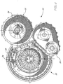
- Fig. 2 is a front view of the gas turbine engine of Fig. 1 .
- Fig. 3 is a partial cross-sectional view of the gas turbine engine of Fig. 1 .
- Engine 10 includes a gas generator module 12, a reduction gearbox module 14 and an accessory gearbox module 16.
- the gas generator module 12 generally has a compressor portion 18, a turbine portion 20, and a combustor portion 22. These components are all generally symmetrically placed about the centreline CL of gas generator module 12.
- both the reduction gearbox module 14 and the accessory gearbox module 16 are offset from the main engine centreline CL.
- the offset centreline of the reduction gearbox module 14 is denoted by OCL.
- the compressor portion 18 includes an air inlet 24, a booster stage or boosted rotor type low pressure (LP) compressor 26 (which may be of the type described in co-pending application serial no. USSN-09/680281 . and a centrifugal impeller 28 type high pressure (HP) compressor at the outlet end of a compressor air flow duct 30.
- the air inlet configuration is relatively straight and generally parallel and concentric to each of the centreline axis CL, the compressor portion 18 and the turbine portion 20, as will be discussed further below.
- the turbine portion 20 of the gas generator module 12 is typical and generally includes turbine discs (not shown) connected to a set of drive shafts, in this case an inner LP turbine shaft 36 and an outer HP turbine shaft 38.
- the HP shaft 38 drives the impeller 28, while the LP shaft 36 drives the rotor 26, the reduction gearbox module 14 and the accessory gearbox module 16.
- these components may be driven by different shafts.
- the reduction gearbox module 14 receives input power from an RGB tower shaft 40 drivingly connected, via bevel gear 42 and bevel gear 44, to the LP shaft 36.
- the tower shaft 40 extends at an angle to the main centreline CL and LP turbine shaft 36, and in this case is roughly perpendicular thereto.
- the tower shaft extends through the inlet gas path 30 through a fairing 46.
- a bevel gear set 48 transfers rotational power to an RGB input shaft 50 which, in turn, drives an RGB output shaft 52 through an epicyclic reduction gear train 54.
- the output shaft 52 terminates (in this example) in a propeller flange 56 for connection of a suitable propeller (not shown).
- the epicyclic reduction gear train 54 is typical and generally includes a central sun gear 60, a plurality of planet gears 62 on a carrier 64, mounted for rotation within a fixed outer ring gear 66.
- the sun gear 60 is driven by the input shaft 50 and the planet gear carrier 64 drives the output shaft 52.
- the accessory gearbox module 16 is driven from the LP shaft 36 via an AGB tower shaft 70.
- the AGB output shaft 72 is used to drive accessory devices, such as fuel pumps, starter generators, mechanical fuel controls, air/oil separators, and oil pumps, etc.
- bearings of this embodiment include LP turbine shaft bearings 80, HP turbine shaft bearings 82, an roller bearing 84 and an ball and roller bearing combination 86 supporting the RGB tower shaft 40, a ball bearing 88 and a roller bearing 90 journalling shaft 50, and a ball bearing 92 and a roller bearing 94 journalling shaft 52.
- a ball bearing 96 and roller bearing 98 support the AGB tower shaft 70.
- the operation of the gas generator 12 causes output rotational power to be delivered by the LP turbine shaft 36.
- the LP shaft rotates, which can be at speeds upward of 25,000 to 30,000 RPM, torque is transferred via bevel gear 42 and bevel gear 44, to RGB tower shaft 40, then through bevel gear set 48 to RGB input shaft 50, and through reduction gear train 54 to the RGB output shaft 52.
- the reduced speed of the output shaft 52 is typically around 2000 RPM, but depends on the application.
- the present invention has a reduction gearbox module which is offset from the main centreline, driven by a drive shaft which is angled relative to the main turbine output shaft.
- This offset permits a substantially more compact design to be achieved, with the overall shape approximating the "short and fat" engine envelopes in aircraft designed to be powered by piston engines. It allows the reduction gearbox to be placed more or less laterally beside the gas generator module, significantly shortening the length of the overall unit.
- the gas path is relatively unobstructed by the main gearbox and thus a straighter, 'line-of-sight' inlet air flow is possible.
- the present invention permits a parallel (rather than serial) arrangement of main gearbox and gas generator, which permits the overall length of the gas path to be substantially shortened.
- the benefits of a shorter, straighter gas path are well known.
- the straight inlet also allows 'ram' air pressure effect increase the inlet air pressure in the turboprop when in flight, which improves engine output power and performance.
- the shorter inlet duct length reduces the area where de-icing is required, and the use of the boosted rotor multiplies the benefit in this respect.
- the shaft 40 of the present invention extends at an angle to the main centreline CL (i.e. is not parallel to it), and in this case is almost perpendicular thereto. In fact, in this case, the shaft 40 is canted slightly aft to permit a placement for propeller flange 56 which is as close as possible to inlet duct 24.
- the relative positioning of the gas generator module 12 and the reduction gearbox module 14 is a matter of design choice, and the amount of offset and the relative angles between the modules may vary, depending on the parameters of the intended application.
- the present invention also permits the placement of the engine on the wing to be optimized. Typically, it is desirable to keep the engine relatively low on the wing to reduce losses, however the propeller of course cannot be permitted to touch the ground.
- the present invention can permit the prop to be positioned higher, relative to the wing, while the engine is kept lower, which is particularly advantageous in low-wing applications.
- the offset output drive also permits the propeller in a turboprop application to include a double acting propeller pitch control, which offers an additional weight savings.
- the placement of the reduction gearbox module 14 also permits the boosted rotor and high turbine rotor to be removed without disturbing the oil system, which reduces the potential for oil contamination.
Landscapes
- Engineering & Computer Science (AREA)
- Chemical & Material Sciences (AREA)
- Combustion & Propulsion (AREA)
- Mechanical Engineering (AREA)
- General Engineering & Computer Science (AREA)
- Connection Of Motors, Electrical Generators, Mechanical Devices, And The Like (AREA)
- Structures Of Non-Positive Displacement Pumps (AREA)
- Gear Transmission (AREA)
Abstract
Claims (8)
- Moteur à turbine à gaz (10) comprenant :- un module générateur de gaz (12) comprenant un arbre de turbine (36) pour fournir une puissance de sortie de rotation, dans lequel ledit module générateur de gaz (12) comprend une portion de compresseur (18), une portion de chambre de combustion (22), et une portion de turbine (20) : et- un arbre d'entraînement intermédiaire (40) raccordé avec faculté d'entraînement à l'arbre de turbine (36) ; et- un module réducteur (14) comportant un arbre d'entrée de boîtier d'engrenage (50) et un arbre de puissance de sortie principal (52), dans lequel l'arbre d'entrée de boîtier d'engrenage (50) est raccordé avec faculté d'entraînement à l'arbre d'entraînement intermédiaire (40),caractérisé en ce que :l'arbre d'entraînement intermédiaire (40) est incliné à l'amère formant un angle avec l'arbre de turbine (36) ;le module générateur de gaz (12) comporte un trajet d'air d'admission (30) et l'arbre d'entraînement intermédiaire (40) s'étend à travers le trajet d'air d'admission (30) à travers un carénage (46) ; etledit module réducteur (14) est disposé sensiblement latéralement à côté du module générateur de gaz (12).
- Moteur à turbine à gaz (10) selon la revendication 1, dans lequel le trajet d'air d'admission (30) est sensiblement droit et sensiblement non obstrué par le module réducteur (14).
- Moteur à turbine à gaz (10) selon la revendication 1 ou 2, dans lequel le trajet d'air d'admission (30) est sensiblement parallèle à un axe longitudinal (CL) du module générateur de gaz (12).
- Moteur à turbine à gaz (10) selon l'une quelconque des revendications précédentes, dans lequel l'arbre de turbine (36) et l'arbre d'entrée de boîtier d'engrenage (50) sont sensiblement parallèles.
- Moteur à turbine à gaz (10) selon l'une quelconque des revendications précédentes, dans lequel l'arbre de turbine (36) comprend une roue conique (42) adaptée pour entraîner avec faculté de rotation l'arbre intermédiaire (40).
- Moteur à turbine à gaz (10) selon l'une quelconque des revendications précédentes, dans lequel le module réducteur (14) comporte un moyen de réduction de vitesse d'arbre (54) interposé de façon opérationnelle entre l'arbre d'entrée de boîtier d'engrenage (50) et l'arbre de puissance de sortie principal (52).
- Moteur à turbine à gaz (10) selon l'une quelconque des revendications précédentes, dans lequel l'arbre de puissance de sortie principal (52) est adapté pour permettre le montage d'une hélice sur celui-ci.
- Moteur à turbine à gaz (10) selon l'une quelconque des revendications précédentes, dans lequel le module générateur de gaz (12) comporte une portion avant qui est sensiblement alignée avec une portion avant du module réducteur (14).
Applications Claiming Priority (3)
| Application Number | Priority Date | Filing Date | Title |
|---|---|---|---|
| US10/026,844 US6735954B2 (en) | 2001-12-21 | 2001-12-21 | Offset drive for gas turbine engine |
| US26844 | 2001-12-21 | ||
| PCT/CA2002/001709 WO2003056162A1 (fr) | 2001-12-21 | 2002-11-07 | Turbine a gaz a commande deportee |
Publications (2)
| Publication Number | Publication Date |
|---|---|
| EP1458967A1 EP1458967A1 (fr) | 2004-09-22 |
| EP1458967B1 true EP1458967B1 (fr) | 2012-05-02 |
Family
ID=21834115
Family Applications (1)
| Application Number | Title | Priority Date | Filing Date |
|---|---|---|---|
| EP02774199A Expired - Lifetime EP1458967B1 (fr) | 2001-12-21 | 2002-11-07 | Turbine a gaz a commande deportee |
Country Status (5)
| Country | Link |
|---|---|
| US (2) | US6735954B2 (fr) |
| EP (1) | EP1458967B1 (fr) |
| JP (1) | JP2005513346A (fr) |
| CA (1) | CA2470699C (fr) |
| WO (1) | WO2003056162A1 (fr) |
Families Citing this family (57)
| Publication number | Priority date | Publication date | Assignee | Title |
|---|---|---|---|---|
| GB2420157B (en) * | 2003-05-14 | 2006-06-28 | Rolls Royce Plc | A stator vane assembly for a turbomachine |
| US7055303B2 (en) * | 2003-12-22 | 2006-06-06 | Pratt & Whitney Canada Corp. | Gas turbine engine architecture |
| US7055330B2 (en) * | 2004-02-25 | 2006-06-06 | United Technologies Corp | Apparatus for driving an accessory gearbox in a gas turbine engine |
| US7690186B2 (en) * | 2005-11-09 | 2010-04-06 | Pratt & Whitney Canada Corp. | Gas turbine engine including apparatus to transfer power between multiple shafts |
| US20080016880A1 (en) * | 2006-07-24 | 2008-01-24 | Vittorio Bruno | Gas turbine starter gear shaft and method of manufacture |
| FR2915523A1 (fr) * | 2007-04-27 | 2008-10-31 | Snecma Sa | Dispositif de production d'energie electrique dans un moteur a turbine a gaz a double corps |
| US9719428B2 (en) * | 2007-11-30 | 2017-08-01 | United Technologies Corporation | Gas turbine engine with pylon mounted accessory drive |
| US20090188334A1 (en) * | 2008-01-25 | 2009-07-30 | United Technologies Corp. | Accessory Gearboxes and Related Gas Turbine Engine Systems |
| US8192143B2 (en) * | 2008-05-21 | 2012-06-05 | United Technologies Corporation | Gearbox assembly |
| US20140174056A1 (en) | 2008-06-02 | 2014-06-26 | United Technologies Corporation | Gas turbine engine with low stage count low pressure turbine |
| US8128021B2 (en) | 2008-06-02 | 2012-03-06 | United Technologies Corporation | Engine mount system for a turbofan gas turbine engine |
| US20100005810A1 (en) * | 2008-07-11 | 2010-01-14 | Rob Jarrell | Power transmission among shafts in a turbine engine |
| US8439631B2 (en) * | 2008-09-05 | 2013-05-14 | Rolls-Royce Corporation | Shaft coupling arrangement |
| FR2950109B1 (fr) * | 2009-09-17 | 2012-07-27 | Turbomeca | Turbomoteur a arbres paralleles |
| US9816441B2 (en) * | 2009-03-30 | 2017-11-14 | United Technologies Corporation | Gas turbine engine with stacked accessory components |
| US9650964B2 (en) * | 2010-12-28 | 2017-05-16 | General Electric Company | Accessory gearbox with a starter/generator |
| US8814502B2 (en) | 2011-05-31 | 2014-08-26 | Pratt & Whitney Canada Corp. | Dual input drive AGB for gas turbine engines |
| US9523422B2 (en) | 2011-06-08 | 2016-12-20 | United Technologies Corporation | Flexible support structure for a geared architecture gas turbine engine |
| US8297917B1 (en) | 2011-06-08 | 2012-10-30 | United Technologies Corporation | Flexible support structure for a geared architecture gas turbine engine |
| US9631558B2 (en) | 2012-01-03 | 2017-04-25 | United Technologies Corporation | Geared architecture for high speed and small volume fan drive turbine |
| US8814503B2 (en) | 2011-06-08 | 2014-08-26 | United Technologies Corporation | Flexible support structure for a geared architecture gas turbine engine |
| US8770922B2 (en) | 2011-06-08 | 2014-07-08 | United Technologies Corporation | Flexible support structure for a geared architecture gas turbine engine |
| US9133729B1 (en) | 2011-06-08 | 2015-09-15 | United Technologies Corporation | Flexible support structure for a geared architecture gas turbine engine |
| US9239012B2 (en) | 2011-06-08 | 2016-01-19 | United Technologies Corporation | Flexible support structure for a geared architecture gas turbine engine |
| US9021778B2 (en) | 2011-06-28 | 2015-05-05 | United Technologies Corporation | Differential gear system with carrier drive |
| US8789354B2 (en) | 2012-02-10 | 2014-07-29 | United Technologies Corporation | Gas turbine engine with separate core and propulsion unit |
| US10125693B2 (en) | 2012-04-02 | 2018-11-13 | United Technologies Corporation | Geared turbofan engine with power density range |
| US8572943B1 (en) | 2012-05-31 | 2013-11-05 | United Technologies Corporation | Fundamental gear system architecture |
| US8756908B2 (en) | 2012-05-31 | 2014-06-24 | United Technologies Corporation | Fundamental gear system architecture |
| US20150308351A1 (en) | 2012-05-31 | 2015-10-29 | United Technologies Corporation | Fundamental gear system architecture |
| US9016068B2 (en) | 2012-07-13 | 2015-04-28 | United Technologies Corporation | Mid-turbine frame with oil system mounts |
| EP2971698B1 (fr) | 2013-03-12 | 2021-04-21 | Raytheon Technologies Corporation | Accouplement flexible pour turbine à engrenages |
| US9752500B2 (en) * | 2013-03-14 | 2017-09-05 | Pratt & Whitney Canada Corp. | Gas turbine engine with transmission and method of adjusting rotational speed |
| US10094281B2 (en) | 2014-01-30 | 2018-10-09 | United Technologies Corporation | Gas turbine engine with twin offset gas generators |
| FR3017658B1 (fr) * | 2014-02-18 | 2019-04-12 | Safran Transmission Systems | Boitier d'entrainement d'equipements pour turbomachine |
| FR3020410B1 (fr) * | 2014-04-29 | 2021-09-17 | Snecma | Turbomachine d'aeronef a prelevement de puissance mecanique ameliore |
| US10072732B2 (en) * | 2014-11-19 | 2018-09-11 | Pratt & Whitney Canada Corp. | Gear with optimized gear web shape |
| US9611789B2 (en) * | 2015-03-27 | 2017-04-04 | Pratt & Whitney Canada Corp. | Reduction gearbox for a gas turbine engine |
| US10119465B2 (en) | 2015-06-23 | 2018-11-06 | United Technologies Corporation | Geared turbofan with independent flexible ring gears and oil collectors |
| US10590854B2 (en) * | 2016-01-26 | 2020-03-17 | United Technologies Corporation | Geared gas turbine engine |
| US10717539B2 (en) * | 2016-05-05 | 2020-07-21 | Pratt & Whitney Canada Corp. | Hybrid gas-electric turbine engine |
| US10883424B2 (en) | 2016-07-19 | 2021-01-05 | Pratt & Whitney Canada Corp. | Multi-spool gas turbine engine architecture |
| US11035293B2 (en) | 2016-09-15 | 2021-06-15 | Pratt & Whitney Canada Corp. | Reverse flow gas turbine engine with offset RGB |
| US10738709B2 (en) | 2017-02-09 | 2020-08-11 | Pratt & Whitney Canada Corp. | Multi-spool gas turbine engine |
| US10808624B2 (en) | 2017-02-09 | 2020-10-20 | Pratt & Whitney Canada Corp. | Turbine rotor with low over-speed requirements |
| US11174782B2 (en) | 2017-02-10 | 2021-11-16 | Pratt & Whitney Canada Corp. | Planetary gearbox for gas turbine engine |
| US10746188B2 (en) | 2017-03-14 | 2020-08-18 | Pratt & Whitney Canada Corp. | Inter-shaft bearing connected to a compressor boost system |
| US10215052B2 (en) | 2017-03-14 | 2019-02-26 | Pratt & Whitney Canada Corp. | Inter-shaft bearing arrangement |
| US10260423B2 (en) * | 2017-04-18 | 2019-04-16 | United Technologies Corporation | Towershaft support |
| US10519871B2 (en) | 2017-05-18 | 2019-12-31 | Pratt & Whitney Canada Corp. | Support assembly for a propeller shaft |
| US11072435B2 (en) * | 2018-10-25 | 2021-07-27 | Honeywell International Inc. | Inlet flow structure for turboprop engine |
| US11174916B2 (en) | 2019-03-21 | 2021-11-16 | Pratt & Whitney Canada Corp. | Aircraft engine reduction gearbox |
| US11788464B2 (en) * | 2019-05-30 | 2023-10-17 | Joseph Michael Teets | Advanced 2-spool turboprop engine |
| CN110486165B (zh) * | 2019-07-31 | 2021-05-07 | 中国航发南方工业有限公司 | 涡桨发动机及无人机 |
| JP7340318B2 (ja) * | 2019-12-20 | 2023-09-07 | 株式会社Subaru | 遠心式オイルミストセパレータ、レシプロエンジン及び航空機 |
| US11215077B1 (en) * | 2020-08-17 | 2022-01-04 | Raytheon Technologies Corporation | Integral gear support and bearing damper pedestal |
| US11268453B1 (en) | 2021-03-17 | 2022-03-08 | Pratt & Whitney Canada Corp. | Lubrication system for aircraft engine reduction gearbox |
Citations (11)
| Publication number | Priority date | Publication date | Assignee | Title |
|---|---|---|---|---|
| GB926947A (en) * | 1961-11-27 | 1963-05-22 | Rolls Royce | Improvements relating to gas turbine engine casings |
| US3269118A (en) * | 1965-04-28 | 1966-08-30 | United Aircraft Corp | Accessory case mounting |
| US3680309A (en) * | 1969-09-25 | 1972-08-01 | Garrett Corp | Two-spool auxiliary power unit and control means |
| EP0147351A1 (fr) * | 1983-12-05 | 1985-07-03 | United Technologies Corporation | Structure de support pour palier |
| US4683714A (en) * | 1986-06-17 | 1987-08-04 | General Motors Corporation | Oil scavenge system |
| EP0392401A1 (fr) * | 1989-04-10 | 1990-10-17 | Mtu Motoren- Und Turbinen-Union MàNchen Gmbh | Dispositif de commande de courant pour turbo-statoréacteur |
| US5103631A (en) * | 1989-03-14 | 1992-04-14 | Rolls-Royce Plc | Differential gear assembly |
| US5349814A (en) * | 1993-02-03 | 1994-09-27 | General Electric Company | Air-start assembly and method |
| EP0659234A1 (fr) * | 1993-07-06 | 1995-06-28 | ROLLS-ROYCE plc | Transfert de puissance d'arbre dans des turbo-moteurs a combustion |
| US6058791A (en) * | 1998-03-19 | 2000-05-09 | Alliedsignal, Inc. | Accessory mechanical drive for a gas turbine engine |
| EP1270903B1 (fr) * | 2001-06-19 | 2006-05-17 | Snecma | Dispositif de secours au rallumage d'un turbo-réacteur en auto-rotation |
Family Cites Families (20)
| Publication number | Priority date | Publication date | Assignee | Title |
|---|---|---|---|---|
| US2540991A (en) | 1942-03-06 | 1951-02-06 | Lockheed Aircraft Corp | Gas reaction aircraft power plant |
| US2563744A (en) | 1942-03-06 | 1951-08-07 | Lockheed Aircraft Corp | Gas turbine power plant having internal cooling means |
| US2874585A (en) * | 1957-12-16 | 1959-02-24 | Baldwin Lima Hamilton Corp | Gas turbine with automatic shift responsive to turbine speed and gas pressure |
| DE1124823B (de) | 1959-05-02 | 1962-03-01 | Daimler Benz Ag | Antrieb fuer Flugzeuge |
| US3008296A (en) * | 1959-08-20 | 1961-11-14 | Power Jets Res & Dev Ltd | Turbine power plant |
| DE1108082B (de) | 1960-06-28 | 1961-05-31 | Ernst Heinkel Flugzeugbau G M | Luftfahrzeug mit Propellerturbinen |
| FR1274606A (fr) | 1960-09-14 | 1961-10-27 | Snecma | Turboréacteur de faible dimension axiale notamment pour la sustentation, par réaction, d'aérodynes à décollage vertical |
| US3792586A (en) | 1973-01-22 | 1974-02-19 | Avco Corp | Bearing assembly systems |
| US3958655A (en) | 1973-05-22 | 1976-05-25 | United Turbine Ab & Co., Kommanditbolag | Gas turbine engine for vehicle propulsion |
| GB1559879A (en) | 1976-08-14 | 1980-01-30 | Rolls Royce | Bevel gearing |
| US4183207A (en) | 1978-03-07 | 1980-01-15 | Avco Corporation | Oil-conducting strut for turbine engines |
| US4270408A (en) | 1978-10-13 | 1981-06-02 | General Motors Corporation | Gear drive for gas turbine engine |
| US4478551A (en) | 1981-12-08 | 1984-10-23 | United Technologies Corporation | Turbine exhaust case design |
| US4525995A (en) | 1983-04-04 | 1985-07-02 | Williams International Corporation | Oil scavening system for gas turbine engine |
| US4756664A (en) | 1985-10-03 | 1988-07-12 | Sundstrand Corporation | Scavenge oil system |
| DE3622022A1 (de) | 1986-07-01 | 1988-01-07 | Kloeckner Humboldt Deutz Ag | Gasturbinentriebwerk |
| US4825645A (en) | 1987-09-08 | 1989-05-02 | General Motors Corporation | Power turbine and reduction gear assembly |
| FR2631386A1 (fr) | 1988-05-11 | 1989-11-17 | Snecma | Turbomachine comportant une grille d'entree incorporant des tubes de passage d'huile |
| US5320305A (en) | 1992-07-22 | 1994-06-14 | Lockheed Corporation | Propulsion system for an aircraft providing V/STOL capability |
| US6041589A (en) | 1998-01-09 | 2000-03-28 | General Electric Company | Asymmetric turboprop booster |
-
2001
- 2001-12-21 US US10/026,844 patent/US6735954B2/en not_active Expired - Lifetime
-
2002
- 2002-11-07 EP EP02774199A patent/EP1458967B1/fr not_active Expired - Lifetime
- 2002-11-07 WO PCT/CA2002/001709 patent/WO2003056162A1/fr active Application Filing
- 2002-11-07 JP JP2003556658A patent/JP2005513346A/ja not_active Ceased
- 2002-11-07 CA CA2470699A patent/CA2470699C/fr not_active Expired - Fee Related
-
2004
- 2004-02-25 US US10/536,117 patent/US20090104019A1/en not_active Abandoned
Patent Citations (11)
| Publication number | Priority date | Publication date | Assignee | Title |
|---|---|---|---|---|
| GB926947A (en) * | 1961-11-27 | 1963-05-22 | Rolls Royce | Improvements relating to gas turbine engine casings |
| US3269118A (en) * | 1965-04-28 | 1966-08-30 | United Aircraft Corp | Accessory case mounting |
| US3680309A (en) * | 1969-09-25 | 1972-08-01 | Garrett Corp | Two-spool auxiliary power unit and control means |
| EP0147351A1 (fr) * | 1983-12-05 | 1985-07-03 | United Technologies Corporation | Structure de support pour palier |
| US4683714A (en) * | 1986-06-17 | 1987-08-04 | General Motors Corporation | Oil scavenge system |
| US5103631A (en) * | 1989-03-14 | 1992-04-14 | Rolls-Royce Plc | Differential gear assembly |
| EP0392401A1 (fr) * | 1989-04-10 | 1990-10-17 | Mtu Motoren- Und Turbinen-Union MàNchen Gmbh | Dispositif de commande de courant pour turbo-statoréacteur |
| US5349814A (en) * | 1993-02-03 | 1994-09-27 | General Electric Company | Air-start assembly and method |
| EP0659234A1 (fr) * | 1993-07-06 | 1995-06-28 | ROLLS-ROYCE plc | Transfert de puissance d'arbre dans des turbo-moteurs a combustion |
| US6058791A (en) * | 1998-03-19 | 2000-05-09 | Alliedsignal, Inc. | Accessory mechanical drive for a gas turbine engine |
| EP1270903B1 (fr) * | 2001-06-19 | 2006-05-17 | Snecma | Dispositif de secours au rallumage d'un turbo-réacteur en auto-rotation |
Also Published As
| Publication number | Publication date |
|---|---|
| CA2470699C (fr) | 2010-04-13 |
| WO2003056162A1 (fr) | 2003-07-10 |
| US20030115885A1 (en) | 2003-06-26 |
| US6735954B2 (en) | 2004-05-18 |
| US20090104019A1 (en) | 2009-04-23 |
| EP1458967A1 (fr) | 2004-09-22 |
| CA2470699A1 (fr) | 2003-07-10 |
| JP2005513346A (ja) | 2005-05-12 |
Similar Documents
| Publication | Publication Date | Title |
|---|---|---|
| EP1458967B1 (fr) | Turbine a gaz a commande deportee | |
| US7882691B2 (en) | High to low pressure spool summing gearbox for accessory power extraction and electric start | |
| EP2065585B1 (fr) | Moteur à turbine à gaz doté d'un entraînement accessoire monté sur pylône | |
| US4251987A (en) | Differential geared engine | |
| US7040082B2 (en) | Assistance and emergency drive for electrically-driven accessories | |
| EP3273033B1 (fr) | Prise de puissance d'arbre de turbine | |
| CN112664320A (zh) | 燃气涡轮发动机增压器构造和操作方法 | |
| EP3199782A1 (fr) | Turbine à gaz à boîtier de transmission | |
| EP2372129A2 (fr) | Arrangement de montage pour les accessoires de turbines à gaz | |
| US4796424A (en) | Intake for a turbopropeller gas turbine engine | |
| US20120117940A1 (en) | Gas turbine engine with pylon mounted accessory drive | |
| US11686253B2 (en) | Through-flow gas turbine engine with electric motor and electric generator | |
| WO2017200665A1 (fr) | Système et procédé pour moteur à entraînement intégré à boîte à engrenages principale avant | |
| EP3885551B1 (fr) | Moteur à turbine électrique hybride | |
| CN110657045B (zh) | 飞行器推进机组及具有这种推进机组的飞行器后部 | |
| RU2522208C1 (ru) | Пилон газотурбинного двигателя в сборе и система газотурбинного двигателя | |
| CN111140362A (zh) | 气体涡轮引擎附件的冷却 | |
| US11725592B2 (en) | Aeronautical propulsion system having a low leakage flow rate and improved propulsion efficiency | |
| US9447695B2 (en) | Diffuser seal for geared turbofan or turboprop engines | |
| CN112739896A (zh) | 具有减速机构的涡轮喷气发动机 | |
| US11052994B2 (en) | System for changing the pitch of a turboprop engine comprising an upstream pair of contrarotating propellers | |
| US11624319B2 (en) | Reverse-flow gas turbine engine with electric motor | |
| US20240263586A1 (en) | Turbine engine including transfer gearbox and accessory gearbox |
Legal Events
| Date | Code | Title | Description |
|---|---|---|---|
| PUAI | Public reference made under article 153(3) epc to a published international application that has entered the european phase |
Free format text: ORIGINAL CODE: 0009012 |
|
| 17P | Request for examination filed |
Effective date: 20040713 |
|
| AK | Designated contracting states |
Kind code of ref document: A1 Designated state(s): AT BE BG CH CY CZ DE DK EE ES FI FR GB GR IE IT LI LU MC NL PT SE SK TR |
|
| 17Q | First examination report despatched |
Effective date: 20071116 |
|
| GRAP | Despatch of communication of intention to grant a patent |
Free format text: ORIGINAL CODE: EPIDOSNIGR1 |
|
| GRAS | Grant fee paid |
Free format text: ORIGINAL CODE: EPIDOSNIGR3 |
|
| GRAA | (expected) grant |
Free format text: ORIGINAL CODE: 0009210 |
|
| AK | Designated contracting states |
Kind code of ref document: B1 Designated state(s): DE FR GB |
|
| REG | Reference to a national code |
Ref country code: GB Ref legal event code: FG4D |
|
| REG | Reference to a national code |
Ref country code: DE Ref legal event code: R096 Ref document number: 60242821 Country of ref document: DE Effective date: 20120628 |
|
| PLBE | No opposition filed within time limit |
Free format text: ORIGINAL CODE: 0009261 |
|
| STAA | Information on the status of an ep patent application or granted ep patent |
Free format text: STATUS: NO OPPOSITION FILED WITHIN TIME LIMIT |
|
| 26N | No opposition filed |
Effective date: 20130205 |
|
| REG | Reference to a national code |
Ref country code: DE Ref legal event code: R097 Ref document number: 60242821 Country of ref document: DE Effective date: 20130205 |
|
| REG | Reference to a national code |
Ref country code: FR Ref legal event code: PLFP Year of fee payment: 14 |
|
| REG | Reference to a national code |
Ref country code: FR Ref legal event code: PLFP Year of fee payment: 15 |
|
| PGFP | Annual fee paid to national office [announced via postgrant information from national office to epo] |
Ref country code: DE Payment date: 20161020 Year of fee payment: 15 |
|
| REG | Reference to a national code |
Ref country code: DE Ref legal event code: R082 Ref document number: 60242821 Country of ref document: DE Representative=s name: SCHMITT-NILSON SCHRAUD WAIBEL WOHLFROM PATENTA, DE |
|
| REG | Reference to a national code |
Ref country code: FR Ref legal event code: PLFP Year of fee payment: 16 |
|
| REG | Reference to a national code |
Ref country code: DE Ref legal event code: R119 Ref document number: 60242821 Country of ref document: DE |
|
| REG | Reference to a national code |
Ref country code: FR Ref legal event code: PLFP Year of fee payment: 17 |
|
| PG25 | Lapsed in a contracting state [announced via postgrant information from national office to epo] |
Ref country code: DE Free format text: LAPSE BECAUSE OF NON-PAYMENT OF DUE FEES Effective date: 20180602 |
|
| PGFP | Annual fee paid to national office [announced via postgrant information from national office to epo] |
Ref country code: FR Payment date: 20181024 Year of fee payment: 17 Ref country code: GB Payment date: 20181024 Year of fee payment: 17 |
|
| GBPC | Gb: european patent ceased through non-payment of renewal fee |
Effective date: 20191107 |
|
| PG25 | Lapsed in a contracting state [announced via postgrant information from national office to epo] |
Ref country code: FR Free format text: LAPSE BECAUSE OF NON-PAYMENT OF DUE FEES Effective date: 20191130 Ref country code: GB Free format text: LAPSE BECAUSE OF NON-PAYMENT OF DUE FEES Effective date: 20191107 |