EP1457683B1 - Radiallüfterrad, insbesondere aus Kunststoff - Google Patents
Radiallüfterrad, insbesondere aus Kunststoff Download PDFInfo
- Publication number
- EP1457683B1 EP1457683B1 EP04005006A EP04005006A EP1457683B1 EP 1457683 B1 EP1457683 B1 EP 1457683B1 EP 04005006 A EP04005006 A EP 04005006A EP 04005006 A EP04005006 A EP 04005006A EP 1457683 B1 EP1457683 B1 EP 1457683B1
- Authority
- EP
- European Patent Office
- Prior art keywords
- webs
- radial fan
- plastic
- vanes
- blades
- Prior art date
- Legal status (The legal status is an assumption and is not a legal conclusion. Google has not performed a legal analysis and makes no representation as to the accuracy of the status listed.)
- Expired - Lifetime
Links
Images


Classifications
-
- F—MECHANICAL ENGINEERING; LIGHTING; HEATING; WEAPONS; BLASTING
- F04—POSITIVE - DISPLACEMENT MACHINES FOR LIQUIDS; PUMPS FOR LIQUIDS OR ELASTIC FLUIDS
- F04D—NON-POSITIVE-DISPLACEMENT PUMPS
- F04D29/00—Details, component parts, or accessories
- F04D29/02—Selection of particular materials
- F04D29/023—Selection of particular materials especially adapted for elastic fluid pumps
-
- F—MECHANICAL ENGINEERING; LIGHTING; HEATING; WEAPONS; BLASTING
- F04—POSITIVE - DISPLACEMENT MACHINES FOR LIQUIDS; PUMPS FOR LIQUIDS OR ELASTIC FLUIDS
- F04D—NON-POSITIVE-DISPLACEMENT PUMPS
- F04D29/00—Details, component parts, or accessories
- F04D29/26—Rotors specially for elastic fluids
- F04D29/28—Rotors specially for elastic fluids for centrifugal or helico-centrifugal pumps for radial-flow or helico-centrifugal pumps
- F04D29/281—Rotors specially for elastic fluids for centrifugal or helico-centrifugal pumps for radial-flow or helico-centrifugal pumps for fans or blowers
- F04D29/282—Rotors specially for elastic fluids for centrifugal or helico-centrifugal pumps for radial-flow or helico-centrifugal pumps for fans or blowers the leading edge of each vane being substantially parallel to the rotation axis
-
- F—MECHANICAL ENGINEERING; LIGHTING; HEATING; WEAPONS; BLASTING
- F04—POSITIVE - DISPLACEMENT MACHINES FOR LIQUIDS; PUMPS FOR LIQUIDS OR ELASTIC FLUIDS
- F04D—NON-POSITIVE-DISPLACEMENT PUMPS
- F04D29/00—Details, component parts, or accessories
- F04D29/26—Rotors specially for elastic fluids
- F04D29/28—Rotors specially for elastic fluids for centrifugal or helico-centrifugal pumps for radial-flow or helico-centrifugal pumps
- F04D29/30—Vanes
-
- F—MECHANICAL ENGINEERING; LIGHTING; HEATING; WEAPONS; BLASTING
- F05—INDEXING SCHEMES RELATING TO ENGINES OR PUMPS IN VARIOUS SUBCLASSES OF CLASSES F01-F04
- F05D—INDEXING SCHEME FOR ASPECTS RELATING TO NON-POSITIVE-DISPLACEMENT MACHINES OR ENGINES, GAS-TURBINES OR JET-PROPULSION PLANTS
- F05D2300/00—Materials; Properties thereof
- F05D2300/40—Organic materials
- F05D2300/43—Synthetic polymers, e.g. plastics; Rubber
Definitions
- the invention relates to a radial fan, in particular made of plastic and in particular for a motor vehicle.
- Conventional radial fan wheels eg as out DE 3 312 933 A1 . EP 0 622 548 A . DE 1 041 637 B or US 2002/182079 A1 known, are usually made of a metal sheet or made of plastic. Due to the occurrence of relatively large centrifugal forces at high speeds, deformations of the blades take place so that high voltages occur in the region of the connection sites between the individual blades and the two rings. This is particularly problematic in plastic radial fan wheels.
- a radial fan for a motor vehicle provided with a plurality of arranged between two rings blades, which are designed as hollow profiles, wherein webs are provided between the two walls of the blades, wherein the radius is smaller than the thickness of the web.
- the rigidity of the blades is increased and the stresses in the region of the connection points are reduced, so that higher rotational speeds and thus higher volume flows, as required, for example, for cooling motor vehicles, with plastic Radial fan wheels without the occurrence of material problems can be achieved.
- the stiffness can be further increased in the plastic by reinforcements, for example by glass fibers. As a result of the cavities weight and material can be saved.
- cheaper plastics can be used for the same applications, thus reducing the manufacturing costs. As a result of the lower deformations at high speeds, fewer imbalances occur, so that the operation is safer and the probability of failure is lower.
- the webs are arranged perpendicular to the wall of the blades, so that an optimal stiffening takes place.
- the distance between two webs one to three times, preferably about twice, the distance between the opposite walls of the blades. This results in optimum stiffness with minimal weight.
- the thickness of the webs is approximately equal to or slightly greater than the thickness of the walls of the blades.
- a radius is preferably provided at the transition from a wall to a web, which is preferably slightly smaller than the thickness of the web. The radius reduces the risk of cracking due to a more uniform stress distribution in the critical areas.
- An inventive plastic radial fan 1 for engine cooling of a motor vehicle has six arranged between two parallel rings 2 blades 3, which are connected to each other via tethers 4.
- the outer shape of the blades 3 corresponds to that of conventional blades, ie the blades 3 have in the plane parallel to the rings 2 a slightly curved profile and in the axial direction, perpendicular to the rings 2 extending walls.
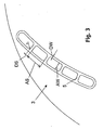
- the blades are 3, as best of all Fig. 3 can be seen formed as a hollow sections with a plurality of continuous webs 5.
- the webs 5 are each arranged substantially perpendicular to the corresponding walls of the blades 3.
- the thickness DS of the webs 5 is slightly larger than the thickness DW of the wall according to the present embodiment.
- the transitions from the webs 5 to the two walls of the blade 3 are rounded with a radius R.
- the radius R is according to the present embodiment, slightly smaller than the thickness DS of the webs 5 and corresponds to the thickness of the wall DW.
- the distance AS between two adjacent webs 5 is about twice as large as the distance AW of the two walls of the blade 3.
Landscapes
- Engineering & Computer Science (AREA)
- Mechanical Engineering (AREA)
- General Engineering & Computer Science (AREA)
- Structures Of Non-Positive Displacement Pumps (AREA)
Description
- Die Erfindung betrifft ein Radiallüfterrad, insbesondere aus Kunststoff und insbesondere für ein Kraftfahrzeug.
- Herkömmliche Radiallüfterräder, z.B. wie aus
DE 3 312 933 A1 ,EP 0 622 548 A ,DE 1 041 637 B oderUS 2002/182079 A1 bekannt, sind in der Regel aus einem Blech gefertigt oder bestehen aus Kunststoff. Auf Grund von auftretenden relativ großen Fliehkräften hoher Drehzahlen erfolgen Verformungen der Schaufeln, so dass es im Bereich der Anbindungsstellen zwischen den einzelnen Schaufeln und den beiden Ringen zu hohen Spannungen kommt. Dies ist insbesondere bei Kunststoff-Radiallüfterrädern problematisch. - Es ist Aufgabe der Erfindung, ein verbessertes Radiallüfterrad, insbesondere aus Kunststoff, zur Verfügung zu stellen.
- Diese Aufgabe wird gelöst durch ein Radiallüfterrad mit den Merkmalen des Anspruchs 1. Vorteilhafte Ausgestaltungen sind Gegenstand der Unteransprüche.
- Erfindungsgemäß ist ein Radiallüfterrad für ein Kraftfahrzeug, mit einer Mehrzahl von zwischen zwei Ringen angeordneten Schaufeln vorgesehen, die als Hohlprofile ausgebildet sind, wobei zwischen den beiden Wänden der Schaufeln Stege vorgesehen sind, wobei der Radius kleiner als die Dicke des Steges ist.
- Durch die doppelwandige Ausgestaltung der Schaufeln, wobei Verbindungsstege vorgesehen sind, werden die Steifigkeit der Schaufeln erhöht und die Spannungen im Bereich der Anbindungsstellen verringert, so dass auch höhere Drehzahlen und somit höhere Volumenströme, wie sie beispielsweise zur Kühlung von Kraftfahrzeugen erforderlich sind, mit Kunststoff-Radiallüfterrädern ohne das Auftreten von Materialproblemen erreicht werden können. Die Steifigkeit kann durch Verstärkungen, beispielsweise durch Glasfasern, im Kunststoff weiter erhöht werden. In Folge der Hohlräume kann Gewicht und Material eingespart werden. Außerdem können für gleiche Anwendungen billigere Kunststoffe verwendet werden, so dass sich die Herstellungskosten verringern. In Folge der geringeren Verformungen bei hohen Geschwindigkeiten treten weniger Unwuchten auf, so dass der Betrieb sicherer und die Ausfallwahrscheinlichkeit geringer ist.
- Vorzugsweise sind die Stege senkrecht zur Wand der Schaufeln angeordnet, so dass eine optimale Versteifung erfolgt.
- Bevorzugt beträgt der Abstand zweier Stege ein- bis dreimal, vorzugsweise ca. zweimal, den Abstand der gegenüberliegenden Wände der Schaufeln. Dies bewirkt eine optimale Steifigkeit bei minimalem Gewicht.
- Vorzugsweise ist die Dicke der Stege etwa gleich oder etwas größer als die Dicke der Wände der Schaufeln. Dabei ist bevorzugt am Übergang von einer Wand zu einem Steg ein Radius vorgesehen, der vorzugsweise etwas kleiner als die Dicke des Steges ist. Der Radius verringert das Risiko von Rissbildungen in Folge einer gleichmäßigeren Spannungsverteilung in den kritischen Bereichen.
- Im folgenden wird die Erfindung anhand eines Ausführungsbeispiels unter Bezugnahme auf die Zeichnung im einzelnen erläutert. In der Zeichnung zeigen:
- Fig. 1
- eine perspektivische Ansicht eines erfindungsgemäßen Radiallüfterrades aus Kunststoff,
- Fig. 2
- eine Detailansicht des Radiallüfterrades von
Fig. 1 und - Fig. 3
- einen Schnitt durch eine Schaufel des Radiallüfterrades von
Fig. 1 . - Ein erfindungsgemäßes Kunststoff-Radiallüfterrad 1 für die Motorkühlung eines Kraftfahrzeugs weist sechs zwischen zwei paralellen Ringen 2 angeordnete Schaufeln 3 auf, welche über Anbindungsstellen 4 miteinander verbunden sind. Die äußere Form der Schaufeln 3 entspricht derjenigen herkömmlicher Schaufeln, d.h. die Schaufeln 3 weisen in der Ebene parallel zu den Ringen 2 ein leicht gekrümmtes Profil und in axialer Richtung, senkrecht zu den Ringen 2 verlaufende Wände auf. Im Gegensatz zu herkömmlichen Schaufeln sind die Schaufeln 3, wie am besten aus
Fig. 3 ersichtlich ist, als Hohlprofile mit einer Mehrzahl von durchgehenden Stegen 5 ausgebildet. Die Stege 5 sind dabei jeweils im wesentlichen senkrecht zu den entsprechenden Wänden der Schaufeln 3 angeordnet. - Die Dicke DS der Stege 5 ist gemäß dem vorliegenden Ausführungsbeispiel etwas größer als die Dicke DW der Wand. Die Übergänge von den Stegen 5 zu den beiden Wänden der Schaufel 3 sind mit einem Radius R abgerundet. Der Radius R ist gemäß dem vorliegenden Ausführungsbeispiel etwas kleiner als die Dicke DS der Stege 5 und entspricht der Dicke der Wand DW. Der Abstand AS zwischen zwei benachbarten Stegen 5 ist etwa doppelt so groß wie der Abstand AW der beiden Wände der Schaufel 3.
-
- 1
- Radiallüfterrad
- 2
- Ring
- 3
- Schaufel
- 4
- Anbindungsstelle
- 5
- Steg
- AS
- Abstand zwischen zwei benachbarten Stegen
- AW
- Abstand der beiden Wände der Schaufel
- DS
- Dicke Steg
- DW
- Dicke Wand
- Radius
- R
Claims (5)
- Radiallüfterrad aus Kunststoff, mit einer Mehrzahl von zwischen zwei Ringen (2) angeordneten Schaufeln (3), wobei die Schaufeln (3) als Hohlprofile ausgebildet sind, wobei zwischen den beiden Wänden der Schaufeln (3) Stege (5) vorgesehen sind, wobei der Radius (R), der am Übergang von einer Wand zu einem Steg (5) vorgesehen ist, kleiner als die Dicke (DS) des Steges (3) ist.
- Radiallüfterrad nach Anspruch 1, dadurch gekennzeichnet, dass die Stege (5) senkrecht zur Wand der Schaufeln (3) angeordnet sind.
- Radiallüfterrad nach Anspruch 1 oder 2, dadurch gekennzeichnet, dass der Abstand (AS) zweier Stege (5) ein- bis dreimal so groß wie der Abstand (AW) der gegenüberliegenden Wände der Schaufeln (3) ist.
- Radiallüfterrad nach Anspruch 3, dadurch gekennzeichnet, dass der Abstand (AS) zweier Stege (5) 1,8 bis 2,2-mal so groß wie der Abstand (AW) der gegenüberliegenden Wände der Schaufeln (3) ist.
- Radiallüfterrad nach einem der vorhergehenden Ansprüche, dadurch gekennzeichnet, dass die Dicke (DS) der Stege (5) gleich oder etwas größer als die Dicke (DW) der Wände der Schaufeln (3) ist.
Applications Claiming Priority (2)
| Application Number | Priority Date | Filing Date | Title |
|---|---|---|---|
| DE10310868 | 2003-03-11 | ||
| DE10310868A DE10310868A1 (de) | 2003-03-11 | 2003-03-11 | Radiallüfterrad, insbesondere aus Kunststoff |
Publications (3)
| Publication Number | Publication Date |
|---|---|
| EP1457683A2 EP1457683A2 (de) | 2004-09-15 |
| EP1457683A3 EP1457683A3 (de) | 2005-11-30 |
| EP1457683B1 true EP1457683B1 (de) | 2009-05-20 |
Family
ID=32748213
Family Applications (1)
| Application Number | Title | Priority Date | Filing Date |
|---|---|---|---|
| EP04005006A Expired - Lifetime EP1457683B1 (de) | 2003-03-11 | 2004-03-03 | Radiallüfterrad, insbesondere aus Kunststoff |
Country Status (2)
| Country | Link |
|---|---|
| EP (1) | EP1457683B1 (de) |
| DE (2) | DE10310868A1 (de) |
Cited By (1)
| Publication number | Priority date | Publication date | Assignee | Title |
|---|---|---|---|---|
| US9022731B2 (en) | 2009-11-03 | 2015-05-05 | Alessandro Seccareccia | Centrifugal ceiling fan |
Families Citing this family (3)
| Publication number | Priority date | Publication date | Assignee | Title |
|---|---|---|---|---|
| DE102009001095A1 (de) | 2009-02-24 | 2010-08-26 | Bfa Anlagen + System Gmbh | Lüfterrad |
| US10415584B2 (en) * | 2017-10-20 | 2019-09-17 | Minebea Mitsumi Inc. | Impeller and fan using the same |
| CN110792635B (zh) * | 2018-08-02 | 2021-07-23 | 宁波方太厨具有限公司 | 一种散热风机及安装有该风机的厨房空气调节系统 |
Family Cites Families (6)
| Publication number | Priority date | Publication date | Assignee | Title |
|---|---|---|---|---|
| GB608703A (en) * | 1940-02-19 | 1948-09-20 | Machf Gebr Stork & Co N V | Improvements in and relating to centrifugal fans |
| DE1041637B (de) * | 1955-06-24 | 1958-10-23 | Licentia Gmbh | Radialgeblaese mit Blechschaufeln |
| DD205221A1 (de) * | 1982-06-01 | 1983-12-21 | Plastluefter & Anlagenbau Veb | Schaufel fuer laufraeder von kreiselarbeitsmaschinen |
| US4565495A (en) * | 1983-08-11 | 1986-01-21 | Electric Power Research Institute, Inc. | Armoring system for an airfoil centrifugal fan |
| DE4308972C1 (de) * | 1993-03-22 | 1994-04-14 | Sunder Plassmann Christoph | Laufrad für Radialventilatoren |
| US6508627B2 (en) * | 2001-05-30 | 2003-01-21 | Lau Industries, Inc. | Airfoil blade and method for its manufacture |
-
2003
- 2003-03-11 DE DE10310868A patent/DE10310868A1/de not_active Withdrawn
-
2004
- 2004-03-03 DE DE502004009498T patent/DE502004009498D1/de not_active Expired - Lifetime
- 2004-03-03 EP EP04005006A patent/EP1457683B1/de not_active Expired - Lifetime
Cited By (1)
| Publication number | Priority date | Publication date | Assignee | Title |
|---|---|---|---|---|
| US9022731B2 (en) | 2009-11-03 | 2015-05-05 | Alessandro Seccareccia | Centrifugal ceiling fan |
Also Published As
| Publication number | Publication date |
|---|---|
| DE502004009498D1 (de) | 2009-07-02 |
| EP1457683A3 (de) | 2005-11-30 |
| EP1457683A2 (de) | 2004-09-15 |
| DE10310868A1 (de) | 2004-09-23 |
Similar Documents
| Publication | Publication Date | Title |
|---|---|---|
| EP2753535B1 (de) | Hybridbauteil und verfahren zur herstellung eines hybridbauteils | |
| EP2154404B1 (de) | Fluidleitung | |
| EP2435237B1 (de) | Strukturbauteil und herstellungsverfahren für ein strukturbauteil | |
| EP3172447B1 (de) | Schaufel für ein laufrad | |
| WO2018153880A1 (de) | Batteriegehäuse für eine fahrzeugbatterie und fahrgestell für ein elektrofahrzeug | |
| EP1954550B1 (de) | Montageträger in hybridstruktur | |
| EP1902220B1 (de) | Laufrad | |
| EP3123581B1 (de) | Leitungsführungseinrichtung mit einstückigem gelenk und entsprechendes kettenglied | |
| EP1161624B1 (de) | Gebauter kolben | |
| EP3789635B1 (de) | Zahnrad | |
| EP2787182B1 (de) | Leitschaufel für eine Strömungsmaschine, Leitschaufelgitter und Verfahren zur Herstellung einer Leitschaufel oder eines Leitschaufelgitters | |
| EP2592264B1 (de) | Blattanschluss für ein Rotorblatt einer Windenergieanlage | |
| WO2008000231A1 (de) | Kunststoffpendelstütze | |
| EP1104368B1 (de) | Platine | |
| EP2170485B1 (de) | Abscheider | |
| DE2944987C3 (de) | Laufschaufel für Dampfturbinen | |
| EP3023185B1 (de) | Um eine oszillations- oder drehachse drehantreibbares werkzeug mit einem antriebsprofil zur kupplung mit einem abtriebsprofil | |
| EP1457683A2 (de) | Radiallüfterrad, insbesondere aus Kunststoff | |
| EP1291266B1 (de) | Hybridträger für ein Kraftfahrzeug | |
| EP2994615B1 (de) | Rotor für eine thermische strömungsmaschine | |
| EP3112589A1 (de) | Turbinenschaufel | |
| EP3724512A1 (de) | Gehäuse hergestellt in einem arbeitsgang | |
| EP2433014B1 (de) | Ventilatorschaufel | |
| DE102018208298A1 (de) | Koppelstange, Radaufhängung und Verfahren zur Herstellung einer Koppelstange | |
| EP3170986A1 (de) | Schaufelcluster mit umfangssicherung |
Legal Events
| Date | Code | Title | Description |
|---|---|---|---|
| PUAI | Public reference made under article 153(3) epc to a published international application that has entered the european phase |
Free format text: ORIGINAL CODE: 0009012 |
|
| AK | Designated contracting states |
Kind code of ref document: A2 Designated state(s): AT BE BG CH CY CZ DE DK EE ES FI FR GB GR HU IE IT LI LU MC NL PL PT RO SE SI SK TR |
|
| AX | Request for extension of the european patent |
Extension state: AL LT LV MK |
|
| PUAL | Search report despatched |
Free format text: ORIGINAL CODE: 0009013 |
|
| AK | Designated contracting states |
Kind code of ref document: A3 Designated state(s): AT BE BG CH CY CZ DE DK EE ES FI FR GB GR HU IE IT LI LU MC NL PL PT RO SE SI SK TR |
|
| AX | Request for extension of the european patent |
Extension state: AL LT LV MK |
|
| 17P | Request for examination filed |
Effective date: 20060530 |
|
| AKX | Designation fees paid |
Designated state(s): DE ES FR IT NL SE |
|
| 17Q | First examination report despatched |
Effective date: 20070111 |
|
| GRAP | Despatch of communication of intention to grant a patent |
Free format text: ORIGINAL CODE: EPIDOSNIGR1 |
|
| GRAS | Grant fee paid |
Free format text: ORIGINAL CODE: EPIDOSNIGR3 |
|
| GRAA | (expected) grant |
Free format text: ORIGINAL CODE: 0009210 |
|
| AK | Designated contracting states |
Kind code of ref document: B1 Designated state(s): DE ES FR IT NL SE |
|
| REF | Corresponds to: |
Ref document number: 502004009498 Country of ref document: DE Date of ref document: 20090702 Kind code of ref document: P |
|
| PG25 | Lapsed in a contracting state [announced via postgrant information from national office to epo] |
Ref country code: ES Free format text: LAPSE BECAUSE OF FAILURE TO SUBMIT A TRANSLATION OF THE DESCRIPTION OR TO PAY THE FEE WITHIN THE PRESCRIBED TIME-LIMIT Effective date: 20090831 |
|
| NLV1 | Nl: lapsed or annulled due to failure to fulfill the requirements of art. 29p and 29m of the patents act | ||
| PG25 | Lapsed in a contracting state [announced via postgrant information from national office to epo] |
Ref country code: NL Free format text: LAPSE BECAUSE OF FAILURE TO SUBMIT A TRANSLATION OF THE DESCRIPTION OR TO PAY THE FEE WITHIN THE PRESCRIBED TIME-LIMIT Effective date: 20090520 Ref country code: SE Free format text: LAPSE BECAUSE OF FAILURE TO SUBMIT A TRANSLATION OF THE DESCRIPTION OR TO PAY THE FEE WITHIN THE PRESCRIBED TIME-LIMIT Effective date: 20090820 |
|
| PLBE | No opposition filed within time limit |
Free format text: ORIGINAL CODE: 0009261 |
|
| STAA | Information on the status of an ep patent application or granted ep patent |
Free format text: STATUS: NO OPPOSITION FILED WITHIN TIME LIMIT |
|
| 26N | No opposition filed |
Effective date: 20100223 |
|
| REG | Reference to a national code |
Ref country code: FR Ref legal event code: ST Effective date: 20101130 |
|
| PG25 | Lapsed in a contracting state [announced via postgrant information from national office to epo] |
Ref country code: FR Free format text: LAPSE BECAUSE OF NON-PAYMENT OF DUE FEES Effective date: 20100331 |
|
| PG25 | Lapsed in a contracting state [announced via postgrant information from national office to epo] |
Ref country code: IT Free format text: LAPSE BECAUSE OF FAILURE TO SUBMIT A TRANSLATION OF THE DESCRIPTION OR TO PAY THE FEE WITHIN THE PRESCRIBED TIME-LIMIT Effective date: 20090520 |
|
| PGFP | Annual fee paid to national office [announced via postgrant information from national office to epo] |
Ref country code: DE Payment date: 20120411 Year of fee payment: 9 |
|
| REG | Reference to a national code |
Ref country code: DE Ref legal event code: R119 Ref document number: 502004009498 Country of ref document: DE Effective date: 20131001 |
|
| PG25 | Lapsed in a contracting state [announced via postgrant information from national office to epo] |
Ref country code: DE Free format text: LAPSE BECAUSE OF NON-PAYMENT OF DUE FEES Effective date: 20131001 |