EP1457406A2 - Reservoir with an integrated bracket - Google Patents
Reservoir with an integrated bracket Download PDFInfo
- Publication number
- EP1457406A2 EP1457406A2 EP04005945A EP04005945A EP1457406A2 EP 1457406 A2 EP1457406 A2 EP 1457406A2 EP 04005945 A EP04005945 A EP 04005945A EP 04005945 A EP04005945 A EP 04005945A EP 1457406 A2 EP1457406 A2 EP 1457406A2
- Authority
- EP
- European Patent Office
- Prior art keywords
- tank
- vehicle
- reservoir
- bracket
- moved
- Prior art date
- Legal status (The legal status is an assumption and is not a legal conclusion. Google has not performed a legal analysis and makes no representation as to the accuracy of the status listed.)
- Granted
Links
- 239000012530 fluid Substances 0.000 claims abstract description 27
- 230000035939 shock Effects 0.000 description 12
- 239000006096 absorbing agent Substances 0.000 description 11
- 229920003002 synthetic resin Polymers 0.000 description 3
- 239000000057 synthetic resin Substances 0.000 description 3
- 238000000034 method Methods 0.000 description 2
- 230000003247 decreasing effect Effects 0.000 description 1
- 238000012423 maintenance Methods 0.000 description 1
- 239000000463 material Substances 0.000 description 1
- 239000002184 metal Substances 0.000 description 1
- 238000012986 modification Methods 0.000 description 1
- 230000004048 modification Effects 0.000 description 1
Images


Classifications
-
- B—PERFORMING OPERATIONS; TRANSPORTING
- B60—VEHICLES IN GENERAL
- B60S—SERVICING, CLEANING, REPAIRING, SUPPORTING, LIFTING, OR MANOEUVRING OF VEHICLES, NOT OTHERWISE PROVIDED FOR
- B60S1/00—Cleaning of vehicles
- B60S1/02—Cleaning windscreens, windows or optical devices
- B60S1/46—Cleaning windscreens, windows or optical devices using liquid; Windscreen washers
- B60S1/48—Liquid supply therefor
- B60S1/50—Arrangement of reservoir
-
- B—PERFORMING OPERATIONS; TRANSPORTING
- B60—VEHICLES IN GENERAL
- B60R—VEHICLES, VEHICLE FITTINGS, OR VEHICLE PARTS, NOT OTHERWISE PROVIDED FOR
- B60R21/00—Arrangements or fittings on vehicles for protecting or preventing injuries to occupants or pedestrians in case of accidents or other traffic risks
- B60R21/34—Protecting non-occupants of a vehicle, e.g. pedestrians
-
- B—PERFORMING OPERATIONS; TRANSPORTING
- B60—VEHICLES IN GENERAL
- B60T—VEHICLE BRAKE CONTROL SYSTEMS OR PARTS THEREOF; BRAKE CONTROL SYSTEMS OR PARTS THEREOF, IN GENERAL; ARRANGEMENT OF BRAKING ELEMENTS ON VEHICLES IN GENERAL; PORTABLE DEVICES FOR PREVENTING UNWANTED MOVEMENT OF VEHICLES; VEHICLE MODIFICATIONS TO FACILITATE COOLING OF BRAKES
- B60T11/00—Transmitting braking action from initiating means to ultimate brake actuator without power assistance or drive or where such assistance or drive is irrelevant
- B60T11/10—Transmitting braking action from initiating means to ultimate brake actuator without power assistance or drive or where such assistance or drive is irrelevant transmitting by fluid means, e.g. hydraulic
- B60T11/26—Reservoirs
-
- B—PERFORMING OPERATIONS; TRANSPORTING
- B62—LAND VEHICLES FOR TRAVELLING OTHERWISE THAN ON RAILS
- B62D—MOTOR VEHICLES; TRAILERS
- B62D5/00—Power-assisted or power-driven steering
- B62D5/06—Power-assisted or power-driven steering fluid, i.e. using a pressurised fluid for most or all the force required for steering a vehicle
- B62D5/062—Details, component parts
-
- B—PERFORMING OPERATIONS; TRANSPORTING
- B60—VEHICLES IN GENERAL
- B60R—VEHICLES, VEHICLE FITTINGS, OR VEHICLE PARTS, NOT OTHERWISE PROVIDED FOR
- B60R21/00—Arrangements or fittings on vehicles for protecting or preventing injuries to occupants or pedestrians in case of accidents or other traffic risks
- B60R21/34—Protecting non-occupants of a vehicle, e.g. pedestrians
- B60R2021/343—Protecting non-occupants of a vehicle, e.g. pedestrians using deformable body panel, bodywork or components
Definitions
- This invention relates to a reservoir that a bracket is integrated with, more particularly to a reservoir that is installed into engine compartments of vehicles.
- Japanese Utility-Model Publication No. 6-16172 discloses a reservoir to reserve various oil such as power steering oil for vehicles.
- this reservoir comprises a tank made of synthetic resin and a bracket made of metal to attach the tank with a body of the vehicle, a reservoir in which a tank and a bracket are integrally molded of synthetic resin is known.
- Japanese Laid-Open Patent Application No. 8-258668 discloses a method for protecting a pedestrian who is hit by a vehicle.
- the pedestrian is thrown up by a front bumper of the vehicle and received by an engine hood according to the method.
- shock of the pedestrian collided to the engine hood is relieved by deformation of the engine hood. That is, the engine hood is deformed downwardly by collision of the pedestrian, and functions as a shock absorber.
- a reservoir is arranged upward into an engine compartment, because of easy access for oil maintenance, and is rigidly fixed to a body of the vehicle. Therefore, the deformed engine hood collides with the reservoir, and further deformation of the engine hood is prevented by the reservoir. This means that ability of the engine hood as the shock absorber for the pedestrian is deteriorated.
- a first aspect of the present invention provides a reservoir to reserve fluid for a vehicle.
- the reservoir comprises a tank reserving the fluid, a bracket integrated with the tank to install the tank in the vehicle, and an attaching portion arranged with the bracket.
- the attaching portion is configured so that the tank can be moved for the vehicle to absorb force that acts to the tank when the tank receives force larger than a predetermined value.
- a second aspect of the present invention provides another reservoir to reserve fluid for a vehicle.
- the reservoir comprises a tank reserving the fluid, a bracket integrated with the tank to install the tank in the vehicle, an attaching portion arranged with the bracket to be fixed to the vehicle, and a connecting portion arranged with the bracket to connect the attaching portion to the tank.
- the connecting portion is configured so that the tank can be moved for the vehicle to absorb force that acts to the tank when the tank receives force larger than a predetermined value.
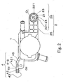
- a reservoir as a first embodiment of the present invention will be described with reference to Figs. 1-4.
- the reservoir that is arranged at upper place into an engine compartment of a vehicle as one of components of a power steering apparatus mainly comprises a tank 1 and a first and a second brackets 2, 4. Oil for the power steering apparatus is reserved into the tank 1.
- the reservoir is fixed to a body of the vehicle in the engine compartment by the brackets 2, 4 and bolts 9 as fixtures.
- Material of the tank 1 and brackets 2, 4 is synthetic resin, and the brackets 2, 4 are integrally molded with the tank 1.
- the first bracket 2 is horizontally formed on an upper portion of the tank 1.
- the first bracket 2 comprises a first attaching portion 29 and a first connecting portion 25 that connects the tank 1 to the first attaching portion 29.
- a through hole 219 in which the bolt 9 is inserted is formed in the center of the first attaching portion 29.
- Plural arc-shaped concavities (four in this embodiment) 221 are formed on the first attaching portion 29 around the through hole 219 concentrically.
- a boss portion 21 around the through hole 29, a flange portion 23 located at the outside of the arc-shaped concavities 221 and rib portions 24 connecting the flange portion 23 to the boss portion 21 are formed on the attaching portion 29.
- the flange portion 23 is continued to the tank 1 along both edges of the first connecting portion 25 and the middle of them.
- the first connecting portion 25 is separated by the continued flange portions and ribs connecting them so that plural concavities (six in this embodiment) are formed on the first connecting portion 25.
- the above-described first bracket 2 functions as a shock absorber for force acting on the reservoir. That is, when the tank 1 receives excessive force (larger than a predetermined value) of its side direction, plastic deformation furthermore subsidiary fracture occur at the rib portions 24 and plane portions 22 that are thin bottoms of the arc-shaped concavities 221, which are located between the flange portion 23 and the boss portion 21. The excessive force that the tank 1 receives is absorbed by the plastic deformation or the subsidiary fracture of the rib portions 24 and the thin plane portions 22.
- a notch 3 is formed at a middle of the first connecting portion 25. That is, section modules of the connecting portion 25 in its side view (the longitudinal direction) are decreased at the portion where the notch 3 is formed. Longitudinal location of a vertex of the notch 3 accords with the location of one of the ribs defining the concavities on the first connecting portion 25. Therefore, according to the first bracket 2, the first connecting portion 25 functions as a shock absorber for force of a direction that is parallel to the line O 1 -O 1 . That is, when the tank 1 receives excessive force (larger than a predetermined vale) of its ups and downs direction, plastic deformation furthermore subsidiary fracture occur at notch 3 of the first connecting portion 25.
- the excessive force that the tank 1 receives is absorbed by the plastic deformation or the subsidiary fracture at the notch 3 of the first connecting portion 25. Further, because the section modules of the connecting portion 25 are small at the notch 3, stress concentration occurs at the notch 3 rather than a root 27 of the first connecting portion 25. Therefore, not the root 27 but the notch 4 of the first connecting portion is fractured by the excessive force. If the connecting portion 25 is fractured at the root 27, the tank 1 also may be broken up. Breakage of the tank 1 causes of oil leak. However, according to the above-described first bracket 2, the connecting portion 25 is not fractured at the root 27. Therefore, oil leak is prevented, even if the tank 1 received the excessive force.
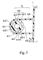
- the second bracket 4 is vertically formed on a middle in the vertical direction and a side in the horizontal direction of the tank 1.
- the second bracket 4 comprises an second attaching portion 49 and a second connecting portion 45 that connects the tank 1 to the attaching portion 49.
- a through hole 419 in which the bolt 9 is inserted is formed in the center of the second attaching portion 49.
- Plural arc-shaped concavities (four in this embodiment) 421 are formed on the second attaching portion 49 around the through hole 419 concentrically.
- a boss portion 41 around the through hole 419, a flange portion 43 located at the outside of the arc-shaped concavities 421 and rib portions 44 connecting the flange portion 43 to the boss portion 41 are formed on the second attaching portion 49.
- the flange portion 43 is continued to the tank 1 along both edges of the connecting portion 45.
- the above-described second bracket 4 functions as a shock absorber for force acting on the reservoir. That is, when the tank 1 receives excessive force (larger than a predetermined vale) of its side direction, plastic deformation, furthermore subsidiary fracture occur at the rib portions 44 and plane portions 42 that are thin bottoms of the arc-shaped concavities 421, which are located between the flange portion 43 and the boss portion 41. The excessive force that the tank 1 received is absorbed by the plastic deformation or the subsidiary fracture of the rib portions 44 and the thin plane portion 42.
- the P direction force causes the plastic deformation or the subsidiary fracture of the rib portions 24 and the thin plane portions 22 because the tank 1 is inclined in the direction as shown by an arrow T2.
- the flange portion 23 which is connected with the tank 1 and the boss portion 21 which is fixed by the bolt 9 become to be able to move relatively in order to absorb force acting on the reservoir.
- the tank 1 since the impact strength acting to the tank 1 is absorbed by the plastic deformation and subsidiary fracture of the first and/or the second brackets 2,4, damage that the pedestrian who is thrown up the engine hood of the vehicle receives is reduced. Further, since the tank 1 can be turned because of the plastic deformation and subsidiary fracture of the first and/or the second brackets 2, 4, further deformation of the engine hood is not prevented by the tank 1. Namely, the tank 1 not only has shock-absorbing function itself and but also does not prevent shock-absorbing function of the engine hood. Therefore, the pedestrian who is hit by the vehicle and thrown up on the engine hood can be protected.
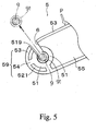
- a reservoir as a second embodiment of the present invention will be described with reference to Fig. 5. Because only the second bracket 4 of the first embodiment is different with the same of the second embodiment, a second bracket 5 of the second embodiment will be described and description for others will be omitted.
- the second bracket 5 is vertically formed on middle in the vertical direction and side in the horizontal direction of the tank 1.
- the second bracket 5 comprises a second attaching portion 59 and a second connecting portion 55 that connects the tank 1 to the second attaching portion 59.
- a through hole 519 in which the bolt 9 is inserted together with a collar 91 is formed in the center of the second attaching portion 59.
- Plural arc-shaped concavities (two in this embodiment) 521 are formed on the second attaching portion 59 around the through hole 519 concentrically.
- a boss portion 51 around the through hole 519, a flange portion 53 located at the out side of the arc-shaped concavities 521 and rib portions 54 connecting the flange portion 53 to the boss portion 51 are formed on the second attaching portion 59.
- the flange portion 53 is continued to the tank 1 along both edges of the second connecting portion 45.
- a slit 6 that is continued to the through hole 59 is upwardly formed at the second attaching portion 59.
- a width of the slit 6 is defined to be slightly narrower than the diameter of the collar 91.
- the above-described second bracket 5 functions as a shock absorber for impact strength shown by the arrow P. That is, when the tank 1 receives excessive force (larger than a predetermined value) of its ups and downs direction, the bolt 9 and the collar 91 are detached from the through hole 519. Then, the second attaching portion 59 is deformed to be widened so that the collar 91 goes through, and the collar 91 slides on the slit 6. Therefore, the impact strength that the tank 1 receives is absorbed by the deformation of the attaching portion 59 and the friction between the collar 91 and walls defining the slit 6. Further, because the bolt 9 is detached from the through hole 519, the tank 1 becomes being able to be turned. Therefore, further deformation of the engine hood is not prevented by the tank 1.
- first and the second brackets 2, 4 that function as the shock absorber are used according to the first and the second embodiments, it is possible that only one of the first and second brackets 2, 4 is used. Further, it is possible that one of the first and the second brackets 2, 4 that functions as the shock absorber and another bracket that does not function as such shock absorber are used. Furthermore, although both of the attaching portion 29 and the connecting portion 25 of the first bracket 2 function as the shock absorber, it is possible that a bracket that functions as the shock absorber at only one of the attaching portion and connecting portion is used.
- a reservoir to reserve fluid for a vehicle comprises a tank and two brackets integrated with the tank to install the tank in the vehicle.
- An attaching portion is arranged with each of the brackets to be fixed to the vehicle.
- a connecting portion is arranged with each of the brackets to connect the attaching portion to the tank.
- One of the connecting portion has a notch that is deformed or fractured so that the tank can be moved for the vehicle to absorb force that acts to the tank when the tank receives force larger than a predetermined value.
- the attaching portion has plural rib portions that is deformed or fractured so that the tank can be moved for the vehicle to absorb force that acts to the tank when the tank receives a force larger than a predetermined value.
Landscapes
- Engineering & Computer Science (AREA)
- Mechanical Engineering (AREA)
- Transportation (AREA)
- Chemical & Material Sciences (AREA)
- Combustion & Propulsion (AREA)
- Water Supply & Treatment (AREA)
- Power Steering Mechanism (AREA)
- Transmission Of Braking Force In Braking Systems (AREA)
- Cooling, Air Intake And Gas Exhaust, And Fuel Tank Arrangements In Propulsion Units (AREA)
- Supply Devices, Intensifiers, Converters, And Telemotors (AREA)
Abstract
Description
Claims (16)
- A reservoir to reserve fluid for a vehicle comprising:a tank reserving the fluid;a bracket integrated with the tank to install the tank in the vehicle; andan attaching portion arranged with the bracket and configured so that the tank can be moved for the vehicle to absorb force that acts to the tank when the tank receives force larger than a predetermined value.
- A reservoir to reserve fluid for a vehicle according to claim 1, wherein:the attaching portion comprises a boss portion fixed to the vehicle and a flange portion arranged around the boss portion and connected to the tank; andthe flange portion can be moved for the boss portion so as to absorb the force that acts to the tank when the tank receives the force larger than the predetermined value.
- A reservoir to reserve fluid for a vehicle according to claim 2, wherein:the attaching portion comprises plural rib portions connecting the boss portion to the flange portion; andthe rib portions can be deformed so that the tank is moved for the vehicle.
- A reservoir to reserve fluid for a vehicle according to claim 3, wherein:the attaching portion further comprises plural thin plane portions that are connecting the boss portion to the flange portion and arranged between the rib portions; andthe thin plane portions can be also deformed so that the tank is moved for the vehicle.
- A reservoir to reserve fluid for a vehicle according to claim 2, wherein:the attaching portion comprises plural rib portions connecting the boss portion to the flange portion; andthe rib portions can be fractured so that the tank is moved for the vehicle.
- A reservoir to reserve fluid for a vehicle according to claim 3, wherein:the attaching portion further comprises plural thin plane portions that are connecting the boss portion to the flange portion and arranged between the rib portions; andthe thin plane portions can be also fractured so that tank is moved for the vehicle.
- A reservoir to reserve fluid for a vehicle according to claim 1, wherein
the attaching portion comprises a boss portion in which a through hole is formed so that a fixture to fix the tank with the vehicle is inserted in, and a slit configured so that the fixture can be detached from the through hole; and
the fixture is detached from the through hole when the tank receives the force larger than the predetermined value. - A reservoir to reserve fluid for a vehicle comprising:a tank reserving the fluid;a bracket integrated with the tank to install the tank in the vehicle;an attaching portion arranged with the bracket to be fixed to the vehicle; anda connecting portion arranged with the bracket to connect the attaching portion to the tank and configured so that the tank can be moved for the vehicle to absorb force that acts to the tank when the tank receives force larger than a predetermined value.
- A reservoir to reserve fluid for a vehicle according to claim 8, wherein:the connecting portion comprises a notch that is defined as a portion which section modules in the longitudinal direction is smaller than other portions; andthe notch can be deformed so that the tank is moved for the vehicle.
- A reservoir to reserve fluid for a vehicle according to claim 8, wherein:the connecting portion comprises a notch that is defined as a portion which section modules in the longitudinal direction is smaller than other portions; andthe notch can be fractured so that the tank is moved for the vehicle.
- A reservoir to reserve fluid for a vehicle comprising:a tank reserving the fluid;a first and a second brackets integrated with the tank to install the tank in the vehicle;a first attaching portion arranged with the first bracket and configured so that the tank can be moved in the horizontal direction for the vehicle to absorb force that acts to the tank in the horizontal direction when the tank receives force larger than a predetermined value;a second attaching portion arranged with the second bracket and configured so that the tank can be moved in the vertical direction for the vehicle to absorb force that acts to the tank in the vertical direction when the tank receives the force larger than the predetermined value.
- A reservoir to reserve fluid for a vehicle comprising:a tank reserving the fluid;a first and a second brackets integrated with the tank to install the tank in the vehicle;a first attaching portion arranged with the bracket to be fixed to the vehicle;a first connecting portion arranged with the first bracket to connect the first attaching portion to the tank and configured so that the tank can be moved for the vehicle to absorb force that acts to the tank when the tank receives force larger than a predetermined value; anda second attaching portion arranged with the second bracket and configured so that the tank can be moved for the vehicle to absorb force that acts to the tank when the tank receives the force larger than the predetermined value.
- A reservoir to reserve fluid for a vehicle according to claim 12, wherein:the first connecting portion comprises a notch that is defined as a portion which section modules in the longitudinal direction is smaller than other portions; andthe second attaching portion comprises a boss portion fixed to the vehicle, a flange portion arranged around the boss portion and connected to the tank, and plural rib portions connection the boss portion to the flange portion.
- A reservoir to reserve fluid for a vehicle according to claim 13, wherein:the notch can be deformed or fractured so that the tank is moved for the vehicle; andthe rib portion can be deformed or fractured so that the tank is moved for the vehicle.
- A reservoir to reserve fluid for a vehicle comprising:a tank reserving the fluid;a bracket integrated with the tank to install the tank in the vehicle; andabsorbing means arranged with the bracket for absorbing force that acts to the tank when the tank receives force larger than a predetermined value.
- A vehicle comprises:an engine compartment;an engine hood covering the engine compartment; anda reservoir installed at a place that is upper in the engine compartment and close to the engine hood, wherein the reservoir comprises a tank reserving the fluid, a bracket integrated with the tank to install the tank in the vehicle, and a attaching portion arranged with the bracket and configured so that the tank can be moved for the vehicle to absorb force that acts to the tank when the tank receives force larger than a predetermined value.
Applications Claiming Priority (2)
| Application Number | Priority Date | Filing Date | Title |
|---|---|---|---|
| JP2003065923 | 2003-03-12 | ||
| JP2003065923A JP4089473B2 (en) | 2003-03-12 | 2003-03-12 | Reservoir tank with integrated bracket |
Publications (3)
| Publication Number | Publication Date |
|---|---|
| EP1457406A2 true EP1457406A2 (en) | 2004-09-15 |
| EP1457406A3 EP1457406A3 (en) | 2006-08-16 |
| EP1457406B1 EP1457406B1 (en) | 2008-10-15 |
Family
ID=32767925
Family Applications (1)
| Application Number | Title | Priority Date | Filing Date |
|---|---|---|---|
| EP04005945A Expired - Lifetime EP1457406B1 (en) | 2003-03-12 | 2004-03-11 | Reservoir with an integrated bracket |
Country Status (4)
| Country | Link |
|---|---|
| US (1) | US7374145B2 (en) |
| EP (1) | EP1457406B1 (en) |
| JP (1) | JP4089473B2 (en) |
| DE (1) | DE602004017069D1 (en) |
Cited By (7)
| Publication number | Priority date | Publication date | Assignee | Title |
|---|---|---|---|---|
| WO2008043642A1 (en) * | 2006-10-06 | 2008-04-17 | Faurecia Kunststoffe Automobilsysteme Gmbh | Support for the front unit of a motor vehicle and method for its production |
| FR2964351A1 (en) * | 2010-09-06 | 2012-03-09 | Peugeot Citroen Automobiles Sa | Windscreen washer fluid storage reservoir for motor vehicle, has retractable trough integrated with tank by seal so as to be disintegrated from tank in case of pedestrian impact on trough, where seal is made of high flexible material |
| FR2979310A1 (en) * | 2011-08-30 | 2013-03-01 | Peugeot Citroen Automobiles Sa | Reservoir for storing liquid e.g. brake fluid, for hydraulic braking control device of vehicle, has container and connector configured to allow swing of reservoir in event of contact of reservoir with cap during pedestrian shock |
| DE102009036617B4 (en) * | 2008-08-07 | 2015-01-08 | Mitsubishi Jidosha Kogyo Kabushiki Kaisha | Mounting structure for washer inlet |
| FR3019513A1 (en) * | 2014-04-04 | 2015-10-09 | Peugeot Citroen Automobiles Sa | FLUID RESERVOIR ARRANGEMENT, ESPECIALLY BRAKE LIQUID TANK ON A VEHICLE |
| DE102015213107A1 (en) * | 2015-07-13 | 2017-01-19 | Volkswagen Aktiengesellschaft | Windscreen cleaning system for a vehicle |
| FR3059287A1 (en) * | 2016-11-29 | 2018-06-01 | Renault S.A.S. | SYSTEM FOR FIXING A COOLING JAR IN A VEHICLE |
Families Citing this family (15)
| Publication number | Priority date | Publication date | Assignee | Title |
|---|---|---|---|---|
| ATE195513T1 (en) * | 1994-04-11 | 2000-09-15 | Chugai Pharmaceutical Co Ltd | 22-THIAVITAMIN D3 DERIVATIVES |
| JP4598736B2 (en) * | 2006-09-13 | 2010-12-15 | 本田技研工業株式会社 | Reservoir tank mounting structure |
| DE102009030136B4 (en) * | 2009-06-24 | 2021-07-01 | Dr. Ing. H.C. F. Porsche Aktiengesellschaft | Motor vehicle body part |
| JP5353795B2 (en) * | 2010-03-31 | 2013-11-27 | コベルコ建機株式会社 | Work machine |
| DE102013201866A1 (en) * | 2012-09-26 | 2014-03-27 | Montaplast Gmbh | Pedestrian guard arrangement i.e. air filter, for passenger car, has passenger car fastened external bodywork part covering portion of passenger car with motor-fixed components and cup shaped absorber placed on external bodywork part |
| DE102013201870A1 (en) * | 2012-09-26 | 2014-03-27 | Montaplast Gmbh | Pedestrian safety arrangement for motor vehicle, has fixed components which are formed for realizing relative displacement of fixture in relation to external main portion or fixed components in impact to external main portion |
| JP2017019470A (en) * | 2015-07-15 | 2017-01-26 | キャタピラー エス エー アール エル | Synthetic resin tank |
| KR101702786B1 (en) * | 2015-12-30 | 2017-02-06 | 쌍용자동차 주식회사 | Coolant reservoir tank mounting for automobile |
| DE102016224152A1 (en) * | 2016-12-05 | 2018-06-07 | Robert Bosch Gmbh | wiper device |
| US20180339674A1 (en) * | 2017-05-24 | 2018-11-29 | Ford Global Technologies, Llc | Isolated fluid reservoir in a vehicle for pedestrian protection |
| US10611332B2 (en) * | 2017-09-06 | 2020-04-07 | Ford Global Technologies, Llc | Collapsible fluid reservoir in a vehicle for pedestrian protection |
| DE102017217662A1 (en) * | 2017-10-05 | 2019-04-11 | Bayerische Motoren Werke Aktiengesellschaft | Tank assembly on a frame of a motorcycle, frame member for a motorcycle and assembly method |
| JP7268641B2 (en) * | 2020-05-21 | 2023-05-08 | トヨタ車体株式会社 | tank equipment |
| USD984351S1 (en) * | 2021-09-29 | 2023-04-25 | Paccar Inc | Fluid reservoir |
| DE102022121745A1 (en) * | 2022-08-29 | 2024-02-29 | Audi Aktiengesellschaft | Brake system assembly |
Citations (3)
| Publication number | Priority date | Publication date | Assignee | Title |
|---|---|---|---|---|
| JPH0616172U (en) | 1992-07-31 | 1994-03-01 | 豊田工機株式会社 | Mounting device for resin containers |
| JPH08258668A (en) | 1995-03-22 | 1996-10-08 | Toyota Motor Corp | Pedestrian protection airbag system |
| DE10011944A1 (en) | 2000-03-11 | 2001-09-13 | Opel Adam Ag | Fixture of brake reservoir under bonnet in engine space of road vehicle uses one or more supports (6,7) between brake cylinder and the reservoir, which hold the reservoir in an installed position |
Family Cites Families (17)
| Publication number | Priority date | Publication date | Assignee | Title |
|---|---|---|---|---|
| US1638782A (en) * | 1927-08-09 | Poration | ||
| US1321857A (en) * | 1919-11-18 | of detroit | ||
| US1611906A (en) * | 1925-05-27 | 1926-12-28 | Int Motor Co | Tank support |
| JPS54170540U (en) | 1978-05-23 | 1979-12-01 | ||
| US4223899A (en) * | 1978-12-04 | 1980-09-23 | Allis-Chalmers Corporation | Isolated fuel tank |
| JPH0616172A (en) | 1992-06-29 | 1994-01-25 | Mitsubishi Heavy Ind Ltd | Ship with movable bow valve also used for anti-pitching |
| JP3432597B2 (en) * | 1994-05-30 | 2003-08-04 | 本田技研工業株式会社 | Car rear chassis structure |
| JP3457153B2 (en) | 1997-07-24 | 2003-10-14 | 本田技研工業株式会社 | Vehicle wiper device |
| JP3218003B2 (en) | 1998-02-03 | 2001-10-15 | アスモ株式会社 | Wiper device |
| FR2775456B1 (en) | 1998-02-27 | 2000-05-12 | Valeo Systemes Dessuyage | WIPER DEVICE FOR A MOTOR VEHICLE COMPRISING A FIXING PLATE WHICH MAY BE ERASED IN THE EVENT OF IMPACT, AND A PLATINY BELONGING TO SUCH A DEVICE |
| DE19810934C2 (en) * | 1998-03-13 | 2001-04-26 | Daimler Chrysler Ag | Device for fastening a fuel tank |
| JP3603984B2 (en) | 1998-04-24 | 2004-12-22 | 本田技研工業株式会社 | Vehicle wiper device |
| JP4081216B2 (en) | 2000-02-04 | 2008-04-23 | 株式会社ミツバ | Wiper pivot |
| US6820908B1 (en) * | 2000-04-28 | 2004-11-23 | Freundenberg-Nok General Partnership | Isolation mount |
| JP2002127875A (en) | 2000-10-25 | 2002-05-09 | Asmo Co Ltd | Washer device |
| JP4708560B2 (en) | 2000-12-28 | 2011-06-22 | 富士重工業株式会社 | Vehicle wiper device |
| JP4142376B2 (en) * | 2002-09-10 | 2008-09-03 | 本田技研工業株式会社 | Motorcycle fuel tank mounting structure |
-
2003
- 2003-03-12 JP JP2003065923A patent/JP4089473B2/en not_active Expired - Fee Related
-
2004
- 2004-03-10 US US10/796,144 patent/US7374145B2/en not_active Expired - Fee Related
- 2004-03-11 EP EP04005945A patent/EP1457406B1/en not_active Expired - Lifetime
- 2004-03-11 DE DE602004017069T patent/DE602004017069D1/en not_active Expired - Fee Related
Patent Citations (3)
| Publication number | Priority date | Publication date | Assignee | Title |
|---|---|---|---|---|
| JPH0616172U (en) | 1992-07-31 | 1994-03-01 | 豊田工機株式会社 | Mounting device for resin containers |
| JPH08258668A (en) | 1995-03-22 | 1996-10-08 | Toyota Motor Corp | Pedestrian protection airbag system |
| DE10011944A1 (en) | 2000-03-11 | 2001-09-13 | Opel Adam Ag | Fixture of brake reservoir under bonnet in engine space of road vehicle uses one or more supports (6,7) between brake cylinder and the reservoir, which hold the reservoir in an installed position |
Cited By (10)
| Publication number | Priority date | Publication date | Assignee | Title |
|---|---|---|---|---|
| WO2008043642A1 (en) * | 2006-10-06 | 2008-04-17 | Faurecia Kunststoffe Automobilsysteme Gmbh | Support for the front unit of a motor vehicle and method for its production |
| EP2275311A3 (en) * | 2006-10-06 | 2011-02-02 | Faurecia Kunststoffe Automobilsysteme GmbH | Support for the front unit of a motor vehicle and production method |
| US8109560B2 (en) | 2006-10-06 | 2012-02-07 | Faurecia Kunststoffe Automobilsysteme Gmbh | Support for the front unit of a motor vehicle and method for its production |
| DE102009036617B4 (en) * | 2008-08-07 | 2015-01-08 | Mitsubishi Jidosha Kogyo Kabushiki Kaisha | Mounting structure for washer inlet |
| FR2964351A1 (en) * | 2010-09-06 | 2012-03-09 | Peugeot Citroen Automobiles Sa | Windscreen washer fluid storage reservoir for motor vehicle, has retractable trough integrated with tank by seal so as to be disintegrated from tank in case of pedestrian impact on trough, where seal is made of high flexible material |
| FR2979310A1 (en) * | 2011-08-30 | 2013-03-01 | Peugeot Citroen Automobiles Sa | Reservoir for storing liquid e.g. brake fluid, for hydraulic braking control device of vehicle, has container and connector configured to allow swing of reservoir in event of contact of reservoir with cap during pedestrian shock |
| FR3019513A1 (en) * | 2014-04-04 | 2015-10-09 | Peugeot Citroen Automobiles Sa | FLUID RESERVOIR ARRANGEMENT, ESPECIALLY BRAKE LIQUID TANK ON A VEHICLE |
| DE102015213107A1 (en) * | 2015-07-13 | 2017-01-19 | Volkswagen Aktiengesellschaft | Windscreen cleaning system for a vehicle |
| FR3059287A1 (en) * | 2016-11-29 | 2018-06-01 | Renault S.A.S. | SYSTEM FOR FIXING A COOLING JAR IN A VEHICLE |
| WO2018099807A1 (en) * | 2016-11-29 | 2018-06-07 | Renault S.A.S. | System for attaching a coolant bottle in a vehicle |
Also Published As
| Publication number | Publication date |
|---|---|
| EP1457406B1 (en) | 2008-10-15 |
| JP2004268864A (en) | 2004-09-30 |
| DE602004017069D1 (en) | 2008-11-27 |
| US7374145B2 (en) | 2008-05-20 |
| JP4089473B2 (en) | 2008-05-28 |
| US20040238247A1 (en) | 2004-12-02 |
| EP1457406A3 (en) | 2006-08-16 |
Similar Documents
| Publication | Publication Date | Title |
|---|---|---|
| US20040238247A1 (en) | Reservoir that a bracket is integrated with | |
| US10370034B2 (en) | Vehicle body reinforcement structure corresponding to small overlap collision | |
| US20160368535A1 (en) | Front vehicle body structure | |
| US7695056B2 (en) | Floorboard for light-weight vehicle | |
| CN101327772A (en) | Hybrid energy absorber for automobile bumper | |
| US6848738B2 (en) | Vehicle structure for pedestrian protection | |
| US12344313B2 (en) | Side sill reinforcement structure of vehicle | |
| US20150367795A1 (en) | Bumper back beam for vehicle | |
| RU2416534C2 (en) | Shock absorbing device | |
| CN204488630U (en) | Motor vehicle headlamp assembly and the headlight module for power actuated vehicle | |
| US6648400B2 (en) | Rear vehicle body structure for pickup trucks | |
| JP5857655B2 (en) | Vehicle harness arrangement structure | |
| US20160251050A1 (en) | Multi-Functional Footboard Support of a Motor Scooter | |
| KR20090126154A (en) | Fastening structure at the bottom of rear bumper | |
| KR20220163819A (en) | Cowl crossbar | |
| KR100282920B1 (en) | Coupling Structure of Automobile Radiator Support Member | |
| KR200155469Y1 (en) | Bumper structure | |
| KR200147046Y1 (en) | Center pillar upper reinforcement structure | |
| JP2001039196A (en) | Assist grip of automobile | |
| KR20040083280A (en) | Cover for vehicles bumper | |
| KR200147950Y1 (en) | Car Front Side Member | |
| KR100369001B1 (en) | Bumper for vehicle | |
| KR100872337B1 (en) | Reinforcing member for preventing dash of car panel | |
| KR0159852B1 (en) | Air fender of a car | |
| KR100306710B1 (en) | Bottom protection of the car |
Legal Events
| Date | Code | Title | Description |
|---|---|---|---|
| PUAI | Public reference made under article 153(3) epc to a published international application that has entered the european phase |
Free format text: ORIGINAL CODE: 0009012 |
|
| AK | Designated contracting states |
Kind code of ref document: A2 Designated state(s): AT BE BG CH CY CZ DE DK EE ES FI FR GB GR HU IE IT LI LU MC NL PL PT RO SE SI SK TR |
|
| AX | Request for extension of the european patent |
Extension state: AL LT LV MK |
|
| PUAL | Search report despatched |
Free format text: ORIGINAL CODE: 0009013 |
|
| RIC1 | Information provided on ipc code assigned before grant |
Ipc: B60S 1/50 20060101ALI20060629BHEP Ipc: B60R 21/34 20060101AFI20060629BHEP Ipc: B62D 5/06 20060101ALI20060629BHEP |
|
| AK | Designated contracting states |
Kind code of ref document: A3 Designated state(s): AT BE BG CH CY CZ DE DK EE ES FI FR GB GR HU IE IT LI LU MC NL PL PT RO SE SI SK TR |
|
| AX | Request for extension of the european patent |
Extension state: AL LT LV MK |
|
| RAP1 | Party data changed (applicant data changed or rights of an application transferred) |
Owner name: JTEKT CORPORATION |
|
| RIN1 | Information on inventor provided before grant (corrected) |
Inventor name: KIRA, YASUSHIJTEKT CORPORATION Inventor name: HIRANO, YASUHISAJTEKT CORPORATION Inventor name: OHAHSI, TATSUYAJTEKT CORPORATION Inventor name: HAYASHI, YOSHIMASAJTEKT CORPORATION |
|
| 17P | Request for examination filed |
Effective date: 20070124 |
|
| AKX | Designation fees paid |
Designated state(s): DE FR GB |
|
| 17Q | First examination report despatched |
Effective date: 20071001 |
|
| GRAP | Despatch of communication of intention to grant a patent |
Free format text: ORIGINAL CODE: EPIDOSNIGR1 |
|
| GRAS | Grant fee paid |
Free format text: ORIGINAL CODE: EPIDOSNIGR3 |
|
| GRAA | (expected) grant |
Free format text: ORIGINAL CODE: 0009210 |
|
| AK | Designated contracting states |
Kind code of ref document: B1 Designated state(s): DE FR GB |
|
| REG | Reference to a national code |
Ref country code: GB Ref legal event code: FG4D |
|
| REF | Corresponds to: |
Ref document number: 602004017069 Country of ref document: DE Date of ref document: 20081127 Kind code of ref document: P |
|
| PLBE | No opposition filed within time limit |
Free format text: ORIGINAL CODE: 0009261 |
|
| STAA | Information on the status of an ep patent application or granted ep patent |
Free format text: STATUS: NO OPPOSITION FILED WITHIN TIME LIMIT |
|
| PGFP | Annual fee paid to national office [announced via postgrant information from national office to epo] |
Ref country code: DE Payment date: 20090306 Year of fee payment: 6 |
|
| 26N | No opposition filed |
Effective date: 20090716 |
|
| PGFP | Annual fee paid to national office [announced via postgrant information from national office to epo] |
Ref country code: FR Payment date: 20090316 Year of fee payment: 6 |
|
| GBPC | Gb: european patent ceased through non-payment of renewal fee |
Effective date: 20090311 |
|
| PG25 | Lapsed in a contracting state [announced via postgrant information from national office to epo] |
Ref country code: GB Free format text: LAPSE BECAUSE OF NON-PAYMENT OF DUE FEES Effective date: 20090311 |
|
| REG | Reference to a national code |
Ref country code: FR Ref legal event code: ST Effective date: 20101130 |
|
| PG25 | Lapsed in a contracting state [announced via postgrant information from national office to epo] |
Ref country code: FR Free format text: LAPSE BECAUSE OF NON-PAYMENT OF DUE FEES Effective date: 20100331 |
|
| PG25 | Lapsed in a contracting state [announced via postgrant information from national office to epo] |
Ref country code: DE Free format text: LAPSE BECAUSE OF NON-PAYMENT OF DUE FEES Effective date: 20101001 |