EP1457250A1 - Gas separator fixing structure and gas separating device using the same - Google Patents
Gas separator fixing structure and gas separating device using the same Download PDFInfo
- Publication number
- EP1457250A1 EP1457250A1 EP02802053A EP02802053A EP1457250A1 EP 1457250 A1 EP1457250 A1 EP 1457250A1 EP 02802053 A EP02802053 A EP 02802053A EP 02802053 A EP02802053 A EP 02802053A EP 1457250 A1 EP1457250 A1 EP 1457250A1
- Authority
- EP
- European Patent Office
- Prior art keywords
- gas
- gas separator
- fixing structure
- ring
- packing
- Prior art date
- Legal status (The legal status is an assumption and is not a legal conclusion. Google has not performed a legal analysis and makes no representation as to the accuracy of the status listed.)
- Granted
Links
Images

Classifications
-
- B—PERFORMING OPERATIONS; TRANSPORTING
- B01—PHYSICAL OR CHEMICAL PROCESSES OR APPARATUS IN GENERAL
- B01D—SEPARATION
- B01D63/00—Apparatus in general for separation processes using semi-permeable membranes
- B01D63/06—Tubular membrane modules
- B01D63/061—Manufacturing thereof
-
- B—PERFORMING OPERATIONS; TRANSPORTING
- B01—PHYSICAL OR CHEMICAL PROCESSES OR APPARATUS IN GENERAL
- B01D—SEPARATION
- B01D53/00—Separation of gases or vapours; Recovering vapours of volatile solvents from gases; Chemical or biological purification of waste gases, e.g. engine exhaust gases, smoke, fumes, flue gases, aerosols
- B01D53/22—Separation of gases or vapours; Recovering vapours of volatile solvents from gases; Chemical or biological purification of waste gases, e.g. engine exhaust gases, smoke, fumes, flue gases, aerosols by diffusion
-
- B—PERFORMING OPERATIONS; TRANSPORTING
- B01—PHYSICAL OR CHEMICAL PROCESSES OR APPARATUS IN GENERAL
- B01D—SEPARATION
- B01D63/00—Apparatus in general for separation processes using semi-permeable membranes
- B01D63/06—Tubular membrane modules
- B01D63/062—Tubular membrane modules with membranes on a surface of a support tube
- B01D63/063—Tubular membrane modules with membranes on a surface of a support tube on the inner surface thereof
-
- B—PERFORMING OPERATIONS; TRANSPORTING
- B01—PHYSICAL OR CHEMICAL PROCESSES OR APPARATUS IN GENERAL
- B01D—SEPARATION
- B01D63/00—Apparatus in general for separation processes using semi-permeable membranes
- B01D63/06—Tubular membrane modules
- B01D63/062—Tubular membrane modules with membranes on a surface of a support tube
- B01D63/065—Tubular membrane modules with membranes on a surface of a support tube on the outer surface thereof
-
- B—PERFORMING OPERATIONS; TRANSPORTING
- B01—PHYSICAL OR CHEMICAL PROCESSES OR APPARATUS IN GENERAL
- B01D—SEPARATION
- B01D63/00—Apparatus in general for separation processes using semi-permeable membranes
- B01D63/06—Tubular membrane modules
- B01D63/066—Tubular membrane modules with a porous block having membrane coated passages
-
- B—PERFORMING OPERATIONS; TRANSPORTING
- B01—PHYSICAL OR CHEMICAL PROCESSES OR APPARATUS IN GENERAL
- B01D—SEPARATION
- B01D2257/00—Components to be removed
- B01D2257/10—Single element gases other than halogens
- B01D2257/108—Hydrogen
-
- B—PERFORMING OPERATIONS; TRANSPORTING
- B01—PHYSICAL OR CHEMICAL PROCESSES OR APPARATUS IN GENERAL
- B01D—SEPARATION
- B01D2313/00—Details relating to membrane modules or apparatus
- B01D2313/06—External membrane module supporting or fixing means
-
- B—PERFORMING OPERATIONS; TRANSPORTING
- B01—PHYSICAL OR CHEMICAL PROCESSES OR APPARATUS IN GENERAL
- B01D—SEPARATION
- B01D2313/00—Details relating to membrane modules or apparatus
- B01D2313/21—Specific headers, end caps
Definitions
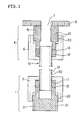
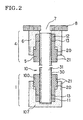
- the cap-like metal member comprises a first cap-like or ring-shaped packing presser which gives a tightening pressure to one gland packing in the axial direction of the tubular support and a ring-shaped or cap-like lower stopper which inhibits movement of the one gland packing
- the ring-shaped metal member comprises a second ring-shaped packing presser which gives a tightening pressure to another gland packing in the axial direction of the tubular support and a ring-shaped upper stopper which inhibits movement of the another gland packing.
- a thread groove 20 may be formed at the portion where the ring-shaped packing pressers 110 and 120 and the ring-shaped stoppers 130 and 140 contact with each other in order to give a tightening pressure to the gland packings 11 and 12 and hold the tightening pressure.
- the material of the cap-like metal member 1 and the ring-shaped metal member 4 is SUS304 (thermal expansion coefficient: 17 ⁇ 10 -6 /°C)
- the thermal expansion coefficient is 2-3 times that of the porous ceramics
- leakage of the extremely small amount of the gas to be treated is supposed to occur with decrease of stress of the gland packings 11 and 12 under high temperature conditions, but the gas separator fixing structure of the present invention can be suitably employed depending on the use of the resulting separated gas (Fig. 1).
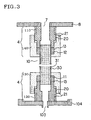
- Fig. 4 is a sectional view which shows one embodiment of the gas separating device of the present invention.
- the gas to be treated which is introduced from an inlet 101 enters into the gas separator 10 from one end thereof through the through hole 7 of the flange 8.
- the separated gas selectively permeates through a gas separation member 30 and flows out of the gas separator 10, and flows out from an outlet 102.
- the gas which does not permeate is discharged from another end of the gas separator 10 through an outlet 103.
- the reference numeral 105 indicates a lid and 106 indicates a fixing member.
- the permissible amount of the gas which leaks from the seal portion depends on the area of the separation membrane, the amount of hydrogen permeating through the separation membrane, and the amount of the gas to be treated permeating through pin holes of the separation membrane. Taking these conditions into consideration, the permissible amount of the gas leaking from the seal portion at 300°C is assumed to be about 30 ml/min.
Landscapes
- Chemical & Material Sciences (AREA)
- Chemical Kinetics & Catalysis (AREA)
- Engineering & Computer Science (AREA)
- Manufacturing & Machinery (AREA)
- Analytical Chemistry (AREA)
- General Chemical & Material Sciences (AREA)
- Oil, Petroleum & Natural Gas (AREA)
- Separation Using Semi-Permeable Membranes (AREA)
- Hydrogen, Water And Hydrids (AREA)
Abstract
Description
| Example | Flow rate of argon gas (ml/min.) | |||
| Temperature of measurement | ||||
| 25 °C | 300 °C | 600 °C | ||
| Number of cycles (times) | 1 | 0.4 | 0.1 | 0.3 |
| 2 | 0.7 | 0.4 | 0.3 | |
| 3 | 0.8 | 0.4 | 0.3 | |
| 4 | 1.0 | 0.5 | 0.4 | |
| 5 | 1.1 | 0.5 | 0.4 |
Claims (22)
- A gas separator fixing structure provided with a gas separator having a gas separation membrane formed on at least one surface of a tubular support having a through hole in axial direction and comprising porous ceramics, characterized in that a cap-like metal member and a ring-shaped metal member are compression-fixed to one and the other open end of the gas separator through seal members, respectively, and seal members are gland packings.
- A gas separator fixing structure according to claim 1, wherein the cap-like metal member comprises a first cap-like or ring-shaped packing presser which gives a tightening pressure to one of the gland packings in the axial direction of the tubular support and a ring-shaped or cap-like lower stopper which inhibits movement of the one of the gland packings, and the ring-shaped metal member comprises a second ring-shaped packing presser which gives a tightening pressure to another gland packing in the axial direction of the tubular support and a ring-shaped upper stopper which inhibits movement of the another gland packing.
- A gas separator fixing structure according to claim 2, wherein the first packing presser has a convex shape which directly presses one of the gland packings by its tip portion, and the lower stopper has a concave shape which directly contacts with the one of the gland packings and fits to the convex shape of the first packing presser, and the second packing presser has a convex shape which directly presses another gland packing by its tip portion, and the upper stopper has a concave shape which directly contacts with the another gland packing and can fit to the convex shape of the second packing presser.
- A gas separator fixing structure provided with a gas separator having a gas separation membrane formed on at least one surface of a tubular support having a through hole in axial direction and comprising porous ceramics, characterized in that ring-shaped metal members are fixed to both open ends of the gas separator through seal members, respectively, and the seal members are gland packings.
- A gas separator fixing structure according to claim 4, wherein the ring-shaped metal member comprises a ring-shaped packing presser which gives a tightening pressure to the gland packing in the axial direction of the tubular support and a ring-shaped stopper which inhibits movement of the gland packing.
- A gas separator fixing structure according to claim 5, wherein the ring-shaped packing presser has a convex shape which directly presses the gland packing by its tip portion, and the ring-shaped stopper has a concave shape which directly contacts with the gland packing and can fit to the convex shape of the ring-shaped packing presser.
- A gas separator fixing structure according to any one of claims 1-6, wherein the tubular support has a plurality of through holes arranged in rows.
- A gas separator fixing structure according to any one of claims 1-7, wherein the maximum value of operating --temperature range of the gland packing is 300°C or higher.
- A gas separator fixing structure according to any one of claims 1-8, wherein the maximum value of operating temperature range of the gland packing in a non-oxidizing atmosphere is 350°C or higher.
- A gas separator fixing structure according to any one of claims 1-9, wherein the maximum value of operating temperature range of the gland packing in a non-oxidizing atmosphere is 600°C or higher.
- A gas separator fixing structure according to any one of claims 1-10, wherein the main component of the gland packings is expanded graphite.
- A gas separator fixing structure according to any one of claims 1-11, wherein the porous ceramics is alumina.
- A gas separator fixing structure according to any one of claims 1-12, wherein the gas separation membrane is a hydrogen separation membrane through which hydrogen selectively permeates.
- A gas separator fixing structure according to any one of claims 1-13, wherein the gas separation membrane comprises palladium or a metal containing palladium.
- A gas separator fixing structure according to any one of claims 1-14, wherein the material constituting the cap-like metal member and/or ring-shaped metal member has a thermal expansion coefficient of 4 × 10⁻⁶ - 10 × 10-6/°C.
- A gas separator fixing structure according to any one of claims 1-15, wherein the material constituting the cap-like metal member and/or ring-shaped metal member is Permalloy.
- A gas separator fixing structure according to any one of claims 1-16 which is used at a temperature in the range of 250-1650°C.
- A gas separator fixing structure according to any one of claims 1-17 which is used at a temperature in the range of 300-600°C.
- A gas separator fixing structure according to any one of claims 1-18 which is used under a pressure of 0.1-10 MPa in the total pressure of the gas to be treated.
- A gas separating device provided with a pressure container, characterized in that the ring-shaped metal member of the gas separator fixing structure according to any one of claims 1-19 is fixed to the inner surface of the pressure container.
- A gas separating device in which a specific gas component in a gas to be treated which flows into the device from an inlet is allowed to permeate a gas separation membrane and to flow out from a first outlet, and the gas which does not permeate through the gas separation member is allowed to flow out from a second outlet, characterized in that the gas separator fixing structure of any one of claims 4-19 is fixed in a container having an inlet, a first outlet and a second outlet.
- A gas separating device according to claim 21 which is provided with a buffer which absorbs expansion of the gas separator.
Applications Claiming Priority (3)
| Application Number | Priority Date | Filing Date | Title |
|---|---|---|---|
| JP2001324411 | 2001-10-23 | ||
| JP2001324411A JP3933907B2 (en) | 2001-10-23 | 2001-10-23 | Gas separator fixing structure and gas separator using the same |
| PCT/JP2002/010961 WO2003035230A1 (en) | 2001-10-23 | 2002-10-22 | Gas separator fixing structure and gas separating device using the same |
Publications (3)
| Publication Number | Publication Date |
|---|---|
| EP1457250A1 true EP1457250A1 (en) | 2004-09-15 |
| EP1457250A4 EP1457250A4 (en) | 2007-06-13 |
| EP1457250B1 EP1457250B1 (en) | 2013-02-27 |
Family
ID=19141141
Family Applications (1)
| Application Number | Title | Priority Date | Filing Date |
|---|---|---|---|
| EP02802053A Expired - Lifetime EP1457250B1 (en) | 2001-10-23 | 2002-10-22 | Gas separating device |
Country Status (4)
| Country | Link |
|---|---|
| US (1) | US6958087B2 (en) |
| EP (1) | EP1457250B1 (en) |
| JP (1) | JP3933907B2 (en) |
| WO (1) | WO2003035230A1 (en) |
Cited By (2)
| Publication number | Priority date | Publication date | Assignee | Title |
|---|---|---|---|---|
| WO2010138454A1 (en) * | 2009-05-28 | 2010-12-02 | Corning Incorporated | Gas separation module |
| EP2711070A4 (en) * | 2011-05-17 | 2015-01-14 | Hitachi Shipbuilding Eng Co | DEVICE FOR ACQUIRING SEPARATION MEMBRANE ELEMENTS FOR SEPARATION MEMBRANE MODULE |
Families Citing this family (26)
| Publication number | Priority date | Publication date | Assignee | Title |
|---|---|---|---|---|
| US7255729B2 (en) * | 2003-05-30 | 2007-08-14 | Noritake Co., Limited | Porous cylindrical-body module, structure for supporting porous cylindrical bodies, and method for fastening a supporting member |
| JP4897233B2 (en) * | 2004-03-31 | 2012-03-14 | 日本アルコール産業株式会社 | Vacuum maintenance device and vacuum maintenance method thereof |
| US7297183B2 (en) * | 2004-09-20 | 2007-11-20 | Idatech, Llc | Hydrogen purification devices, components, and fuel processing systems containing the same |
| RU2292232C2 (en) * | 2004-10-25 | 2007-01-27 | Общество с ограниченной ответственностью "Объединенный центр исследований и разработок" (ООО "ЮРД-Центр") | Reactor for gas separation and/or carrying out chemical reactions and method for manufacturing the same |
| US7923105B2 (en) * | 2004-12-01 | 2011-04-12 | Ngk Insulators, Ltd. | Hydrogen separator and process for production thereof |
| JP4490383B2 (en) * | 2006-03-13 | 2010-06-23 | 日本碍子株式会社 | Hydrogen gas separator fixing structure and hydrogen gas separator using the same |
| JP2008246315A (en) * | 2007-03-29 | 2008-10-16 | Ngk Spark Plug Co Ltd | Hydrogen separator and fuel cell |
| JP2008246314A (en) * | 2007-03-29 | 2008-10-16 | Ngk Spark Plug Co Ltd | Hydrogen separator and fuel cell |
| JP5814506B2 (en) * | 2007-06-11 | 2015-11-17 | 日本碍子株式会社 | Hydrogen separation membrane and selectively permeable membrane reactor |
| CN101687138A (en) * | 2007-07-02 | 2010-03-31 | 株式会社东芝 | Hollow fiber membrane dehumidifier |
| JP5149026B2 (en) * | 2008-02-06 | 2013-02-20 | 日本特殊陶業株式会社 | Hydrogen separator |
| JP4898725B2 (en) * | 2008-03-07 | 2012-03-21 | 日本特殊陶業株式会社 | Hydrogen separator |
| BRPI1013068A2 (en) | 2009-05-18 | 2016-04-05 | Ngk Insulators Ltd | ceramic pervaporation membrane and vapor permeable ceramic membrane |
| JP5749474B2 (en) * | 2010-02-22 | 2015-07-15 | 日本碍子株式会社 | Gas separator fixing structure and method of using gas separator fixing structure |
| JP5554747B2 (en) * | 2010-05-21 | 2014-07-23 | 日本特殊陶業株式会社 | Gas seal composite and apparatus comprising the gas seal composite |
| IT1401192B1 (en) * | 2010-06-16 | 2013-07-12 | Enea Agenzia Naz Per Le Nuove Tecnologie L En E Lo Sviluppo Economico Sostenibile | MEMBRANE REACTOR FOR THE TREATMENT OF GAS CONTAINING TRIZIO |
| WO2012128217A1 (en) | 2011-03-22 | 2012-09-27 | 日本碍子株式会社 | Honeycomb-shaped ceramic separation-membrane structure |
| WO2013054794A1 (en) | 2011-10-11 | 2013-04-18 | 日本碍子株式会社 | Ceramic filter |
| JP6008943B2 (en) | 2012-03-30 | 2016-10-19 | 日本碍子株式会社 | Honeycomb-shaped ceramic porous body, manufacturing method thereof, and honeycomb-shaped ceramic separation membrane structure |
| JP5663634B2 (en) * | 2013-07-16 | 2015-02-04 | 日立造船株式会社 | Membrane separation member of separation membrane module, attachment device for membrane separation member in separation membrane module, and separation membrane module |
| WO2016072421A1 (en) * | 2014-11-05 | 2016-05-12 | 日本碍子株式会社 | Package, method for storing or transporting sub-nano membrane structure, and sub-nano membrane structure |
| WO2017169468A1 (en) | 2016-03-31 | 2017-10-05 | 日本碍子株式会社 | Monolithic separation membrane structure |
| CN108883377B (en) | 2016-03-31 | 2021-05-07 | 日本碍子株式会社 | Porous support, method for producing porous support, separation membrane structure, and method for producing separation membrane structure |
| WO2017169363A1 (en) | 2016-03-31 | 2017-10-05 | 日本碍子株式会社 | Monolithic base material and production method therefor |
| TWI890107B (en) * | 2022-08-02 | 2025-07-11 | 日商日本碍子股份有限公司 | Separation membrane module |
| CN116803958B (en) * | 2023-06-27 | 2024-10-15 | 濮阳天地人环保科技股份有限公司 | Preparation method of ceramic filter element and sewage filtering catalytic oxidation device comprising ceramic filter element |
Family Cites Families (23)
| Publication number | Priority date | Publication date | Assignee | Title |
|---|---|---|---|---|
| US2671337A (en) * | 1951-03-31 | 1954-03-09 | Universal Oil Prod Co | Hydrogen analyzer |
| US3437357A (en) * | 1967-02-01 | 1969-04-08 | Engelhard Ind Inc | Seal for thin tubing |
| US3761382A (en) * | 1972-06-21 | 1973-09-25 | Triangle Environment Corp | Ers and the like apparatus for generating purifying and delivering hydrogen for analyz |
| JPS52135319A (en) * | 1976-05-07 | 1977-11-12 | Nippon Kokuen Kogyo Kk | Packing articles for sleep joint and manufacture |
| JPS5624486Y2 (en) * | 1978-06-08 | 1981-06-09 | ||
| JPS58204880A (en) * | 1982-05-21 | 1983-11-29 | 日立粉末冶金株式会社 | Method of bonding glass or ceramic to sintering material |
| JPS62273030A (en) | 1986-05-20 | 1987-11-27 | Ise Kagaku Kogyo Kk | Method for producing hydrogen separation medium |
| JPS63171617A (en) | 1987-01-09 | 1988-07-15 | Shozaburo Saito | Composite membrane excellent in permselectivity of hydrogen and its production |
| US5131261A (en) * | 1988-08-26 | 1992-07-21 | The Dow Chemical Company | Permeation measurement device |
| DE3916511A1 (en) * | 1989-05-20 | 1990-12-13 | Seitz Filter Werke | MEMBRANE FILTER DEVICE FOR MICRO AND ULTRAFILTRATION OF FLUIDS IN THE CROSSFLOW PROCESS |
| JP2740969B2 (en) * | 1989-10-04 | 1998-04-15 | イビデン株式会社 | Semiconductor mounting substrate |
| US5498278A (en) * | 1990-08-10 | 1996-03-12 | Bend Research, Inc. | Composite hydrogen separation element and module |
| JP3402515B2 (en) * | 1994-05-23 | 2003-05-06 | 日本碍子株式会社 | Hydrogen separator, hydrogen separator using the same, and method for producing hydrogen separator |
| WO2000022690A1 (en) * | 1998-10-14 | 2000-04-20 | Northwest Power Systems, Llc | Fuel processing system |
| US6139810A (en) * | 1998-06-03 | 2000-10-31 | Praxair Technology, Inc. | Tube and shell reactor with oxygen selective ion transport ceramic reaction tubes |
| DE19846041A1 (en) * | 1998-10-07 | 2000-04-20 | Membraflow Gmbh & Co Kg Filter | Membrane module |
| US6248157B1 (en) * | 1999-08-20 | 2001-06-19 | Systec Inc. | Vacuum degassing |
| JP2001246232A (en) * | 2000-03-03 | 2001-09-11 | Japan Gore Tex Inc | Gas permeable membrane device |
| US6454274B2 (en) * | 2000-03-27 | 2002-09-24 | Praxair Technology, Inc. | Joint assembly for joining a ceramic membrane to a tube sheet |
| JP3770791B2 (en) * | 2000-12-19 | 2006-04-26 | 株式会社ノリタケカンパニーリミテド | High temperature type membrane reformer |
| GB0106478D0 (en) * | 2001-03-16 | 2001-05-02 | Univ Robert Gordon | Apparatus and method |
| US6554015B1 (en) * | 2001-08-07 | 2003-04-29 | The United States Of America As Represented By The United States Department Of Energy | Single piece silver/palladium cell for adjusting or measuring a level of hydrogen and methods therefor |
| WO2003024577A1 (en) * | 2001-09-17 | 2003-03-27 | Ngk Insulators, Ltd. | Method for preparing ddr type zeolite film, ddr type zeolite film, and composite ddr type zeolite film, and method for preparation thereof |
-
2001
- 2001-10-23 JP JP2001324411A patent/JP3933907B2/en not_active Expired - Lifetime
-
2002
- 2002-10-22 EP EP02802053A patent/EP1457250B1/en not_active Expired - Lifetime
- 2002-10-22 WO PCT/JP2002/010961 patent/WO2003035230A1/en not_active Ceased
-
2004
- 2004-04-09 US US10/822,131 patent/US6958087B2/en not_active Expired - Lifetime
Cited By (3)
| Publication number | Priority date | Publication date | Assignee | Title |
|---|---|---|---|---|
| WO2010138454A1 (en) * | 2009-05-28 | 2010-12-02 | Corning Incorporated | Gas separation module |
| US8101010B2 (en) | 2009-05-28 | 2012-01-24 | Corning Incorporated | Gas separation module |
| EP2711070A4 (en) * | 2011-05-17 | 2015-01-14 | Hitachi Shipbuilding Eng Co | DEVICE FOR ACQUIRING SEPARATION MEMBRANE ELEMENTS FOR SEPARATION MEMBRANE MODULE |
Also Published As
| Publication number | Publication date |
|---|---|
| US20040187690A1 (en) | 2004-09-30 |
| WO2003035230A1 (en) | 2003-05-01 |
| US6958087B2 (en) | 2005-10-25 |
| JP2003126662A (en) | 2003-05-07 |
| EP1457250A4 (en) | 2007-06-13 |
| JP3933907B2 (en) | 2007-06-20 |
| EP1457250B1 (en) | 2013-02-27 |
Similar Documents
| Publication | Publication Date | Title |
|---|---|---|
| US6958087B2 (en) | Gas separator fixing structure and gas separating device using the same | |
| US7708812B2 (en) | Hydrogen gas separator fixing structure and hydrogen gas separating device using the same | |
| US5518530A (en) | Connected body comprising a gas separator and a metal, and apparatus for separating hydrogen gas from a mixed gas | |
| KR100370447B1 (en) | Seal element, seal assembly, sealing method | |
| US8182592B2 (en) | Shell feed type gas separation membrane module | |
| KR100306016B1 (en) | Modules for filtration, separation, purification or catalytic conversion of gases or liquids | |
| JP3402515B2 (en) | Hydrogen separator, hydrogen separator using the same, and method for producing hydrogen separator | |
| EP2147897B1 (en) | Hydrogen separator and method of operating hydrogen separator | |
| FI122170B (en) | Hydrogen separation membrane | |
| CA2399145C (en) | Hydrogen-permeable structure and method for preparation thereof | |
| US8110022B2 (en) | Hydrogen purifier module and method for forming the same | |
| JP4742233B2 (en) | Ceramic heat exchanger | |
| RU2322285C2 (en) | Method and device for separating gases | |
| JP2008238068A (en) | Hollow fiber membrane module | |
| JP5749474B2 (en) | Gas separator fixing structure and method of using gas separator fixing structure | |
| JP5623819B2 (en) | Gas seal composite and apparatus comprising the gas seal composite | |
| JP2013034913A (en) | Hydrogen separation apparatus | |
| JP4890938B2 (en) | Gas separation tube housing structure | |
| JP4522415B2 (en) | Membrane manufacturing method | |
| JP2007090295A (en) | Hydrogen separation member and method for producing the same | |
| Zheng et al. | Defect size analysis approach combined with silicate gel/ceramic particles for defect repair of Pd composite membranes | |
| JP5012204B2 (en) | Housing-equipped hollow fiber membrane module | |
| JP2003326138A (en) | Method of sealing end of porous ceramic hollow fiber membrane | |
| Haydn et al. | PM Functional Materials: Metal-Supported Palladium Membranes for Hydrogen Separation | |
| JP2008253869A (en) | Shell feed type gas separation membrane module |
Legal Events
| Date | Code | Title | Description |
|---|---|---|---|
| PUAI | Public reference made under article 153(3) epc to a published international application that has entered the european phase |
Free format text: ORIGINAL CODE: 0009012 |
|
| 17P | Request for examination filed |
Effective date: 20040503 |
|
| AK | Designated contracting states |
Kind code of ref document: A1 Designated state(s): AT BE BG CH CY CZ DE DK EE ES FI FR GB GR IE IT LI LU MC NL PT SE SK TR |
|
| AX | Request for extension of the european patent |
Extension state: AL LT LV MK RO SI |
|
| A4 | Supplementary search report drawn up and despatched |
Effective date: 20070516 |
|
| 17Q | First examination report despatched |
Effective date: 20080613 |
|
| GRAP | Despatch of communication of intention to grant a patent |
Free format text: ORIGINAL CODE: EPIDOSNIGR1 |
|
| RTI1 | Title (correction) |
Free format text: GAS SEPARATING DEVICE |
|
| GRAP | Despatch of communication of intention to grant a patent |
Free format text: ORIGINAL CODE: EPIDOSNIGR1 |
|
| GRAS | Grant fee paid |
Free format text: ORIGINAL CODE: EPIDOSNIGR3 |
|
| GRAA | (expected) grant |
Free format text: ORIGINAL CODE: 0009210 |
|
| AK | Designated contracting states |
Kind code of ref document: B1 Designated state(s): CH DE FR GB IT LI |
|
| REG | Reference to a national code |
Ref country code: GB Ref legal event code: FG4D |
|
| REG | Reference to a national code |
Ref country code: CH Ref legal event code: EP |
|
| REG | Reference to a national code |
Ref country code: DE Ref legal event code: R096 Ref document number: 60244588 Country of ref document: DE Effective date: 20130425 |
|
| PLBE | No opposition filed within time limit |
Free format text: ORIGINAL CODE: 0009261 |
|
| STAA | Information on the status of an ep patent application or granted ep patent |
Free format text: STATUS: NO OPPOSITION FILED WITHIN TIME LIMIT |
|
| 26N | No opposition filed |
Effective date: 20131128 |
|
| REG | Reference to a national code |
Ref country code: DE Ref legal event code: R097 Ref document number: 60244588 Country of ref document: DE Effective date: 20131128 |
|
| REG | Reference to a national code |
Ref country code: CH Ref legal event code: PL |
|
| PG25 | Lapsed in a contracting state [announced via postgrant information from national office to epo] |
Ref country code: CH Free format text: LAPSE BECAUSE OF NON-PAYMENT OF DUE FEES Effective date: 20131031 Ref country code: LI Free format text: LAPSE BECAUSE OF NON-PAYMENT OF DUE FEES Effective date: 20131031 |
|
| REG | Reference to a national code |
Ref country code: FR Ref legal event code: PLFP Year of fee payment: 15 |
|
| PGFP | Annual fee paid to national office [announced via postgrant information from national office to epo] |
Ref country code: FR Payment date: 20160919 Year of fee payment: 15 |
|
| PGFP | Annual fee paid to national office [announced via postgrant information from national office to epo] |
Ref country code: GB Payment date: 20161019 Year of fee payment: 15 |
|
| PGFP | Annual fee paid to national office [announced via postgrant information from national office to epo] |
Ref country code: IT Payment date: 20161024 Year of fee payment: 15 |
|
| GBPC | Gb: european patent ceased through non-payment of renewal fee |
Effective date: 20171022 |
|
| REG | Reference to a national code |
Ref country code: FR Ref legal event code: ST Effective date: 20180629 |
|
| PG25 | Lapsed in a contracting state [announced via postgrant information from national office to epo] |
Ref country code: GB Free format text: LAPSE BECAUSE OF NON-PAYMENT OF DUE FEES Effective date: 20171022 |
|
| PG25 | Lapsed in a contracting state [announced via postgrant information from national office to epo] |
Ref country code: FR Free format text: LAPSE BECAUSE OF NON-PAYMENT OF DUE FEES Effective date: 20171031 |
|
| PG25 | Lapsed in a contracting state [announced via postgrant information from national office to epo] |
Ref country code: IT Free format text: LAPSE BECAUSE OF NON-PAYMENT OF DUE FEES Effective date: 20171022 |
|
| PGFP | Annual fee paid to national office [announced via postgrant information from national office to epo] |
Ref country code: DE Payment date: 20210914 Year of fee payment: 20 |
|
| REG | Reference to a national code |
Ref country code: DE Ref legal event code: R071 Ref document number: 60244588 Country of ref document: DE |