EP1455119A2 - Fahrzeug mit hydrostatischem Getriebe - Google Patents
Fahrzeug mit hydrostatischem Getriebe Download PDFInfo
- Publication number
- EP1455119A2 EP1455119A2 EP04005456A EP04005456A EP1455119A2 EP 1455119 A2 EP1455119 A2 EP 1455119A2 EP 04005456 A EP04005456 A EP 04005456A EP 04005456 A EP04005456 A EP 04005456A EP 1455119 A2 EP1455119 A2 EP 1455119A2
- Authority
- EP
- European Patent Office
- Prior art keywords
- actuating device
- vehicle
- vehicle according
- hydraulic pump
- accelerator pedal
- Prior art date
- Legal status (The legal status is an assumption and is not a legal conclusion. Google has not performed a legal analysis and makes no representation as to the accuracy of the status listed.)
- Granted
Links
Images

Classifications
-
- F—MECHANICAL ENGINEERING; LIGHTING; HEATING; WEAPONS; BLASTING
- F16—ENGINEERING ELEMENTS AND UNITS; GENERAL MEASURES FOR PRODUCING AND MAINTAINING EFFECTIVE FUNCTIONING OF MACHINES OR INSTALLATIONS; THERMAL INSULATION IN GENERAL
- F16H—GEARING
- F16H61/00—Control functions within control units of change-speed- or reversing-gearings for conveying rotary motion ; Control of exclusively fluid gearing, friction gearing, gearings with endless flexible members or other particular types of gearing
- F16H61/38—Control of exclusively fluid gearing
- F16H61/40—Control of exclusively fluid gearing hydrostatic
- F16H61/42—Control of exclusively fluid gearing hydrostatic involving adjustment of a pump or motor with adjustable output or capacity
-
- B—PERFORMING OPERATIONS; TRANSPORTING
- B60—VEHICLES IN GENERAL
- B60W—CONJOINT CONTROL OF VEHICLE SUB-UNITS OF DIFFERENT TYPE OR DIFFERENT FUNCTION; CONTROL SYSTEMS SPECIALLY ADAPTED FOR HYBRID VEHICLES; ROAD VEHICLE DRIVE CONTROL SYSTEMS FOR PURPOSES NOT RELATED TO THE CONTROL OF A PARTICULAR SUB-UNIT
- B60W10/00—Conjoint control of vehicle sub-units of different type or different function
- B60W10/04—Conjoint control of vehicle sub-units of different type or different function including control of propulsion units
- B60W10/06—Conjoint control of vehicle sub-units of different type or different function including control of propulsion units including control of combustion engines
-
- B—PERFORMING OPERATIONS; TRANSPORTING
- B60—VEHICLES IN GENERAL
- B60W—CONJOINT CONTROL OF VEHICLE SUB-UNITS OF DIFFERENT TYPE OR DIFFERENT FUNCTION; CONTROL SYSTEMS SPECIALLY ADAPTED FOR HYBRID VEHICLES; ROAD VEHICLE DRIVE CONTROL SYSTEMS FOR PURPOSES NOT RELATED TO THE CONTROL OF A PARTICULAR SUB-UNIT
- B60W30/00—Purposes of road vehicle drive control systems not related to the control of a particular sub-unit, e.g. of systems using conjoint control of vehicle sub-units
- B60W30/18—Propelling the vehicle
- B60W30/182—Selecting between different operative modes, e.g. comfort and performance modes
-
- F—MECHANICAL ENGINEERING; LIGHTING; HEATING; WEAPONS; BLASTING
- F16—ENGINEERING ELEMENTS AND UNITS; GENERAL MEASURES FOR PRODUCING AND MAINTAINING EFFECTIVE FUNCTIONING OF MACHINES OR INSTALLATIONS; THERMAL INSULATION IN GENERAL
- F16H—GEARING
- F16H61/00—Control functions within control units of change-speed- or reversing-gearings for conveying rotary motion ; Control of exclusively fluid gearing, friction gearing, gearings with endless flexible members or other particular types of gearing
- F16H61/38—Control of exclusively fluid gearing
- F16H61/40—Control of exclusively fluid gearing hydrostatic
- F16H61/42—Control of exclusively fluid gearing hydrostatic involving adjustment of a pump or motor with adjustable output or capacity
- F16H61/437—Pump capacity control by mechanical control means, e.g. by levers or pedals
-
- B—PERFORMING OPERATIONS; TRANSPORTING
- B60—VEHICLES IN GENERAL
- B60Y—INDEXING SCHEME RELATING TO ASPECTS CROSS-CUTTING VEHICLE TECHNOLOGY
- B60Y2200/00—Type of vehicle
- B60Y2200/20—Off-Road Vehicles
- B60Y2200/22—Agricultural vehicles
- B60Y2200/222—Harvesters
-
- F—MECHANICAL ENGINEERING; LIGHTING; HEATING; WEAPONS; BLASTING
- F16—ENGINEERING ELEMENTS AND UNITS; GENERAL MEASURES FOR PRODUCING AND MAINTAINING EFFECTIVE FUNCTIONING OF MACHINES OR INSTALLATIONS; THERMAL INSULATION IN GENERAL
- F16H—GEARING
- F16H59/00—Control inputs to control units of change-speed- or reversing-gearings for conveying rotary motion
- F16H59/02—Selector apparatus
- F16H59/04—Ratio selector apparatus
- F16H59/06—Ratio selector apparatus the ratio being infinitely variable
- F16H2059/065—Inching pedals for setting the ratio of a hydrostatic transmission
-
- F—MECHANICAL ENGINEERING; LIGHTING; HEATING; WEAPONS; BLASTING
- F16—ENGINEERING ELEMENTS AND UNITS; GENERAL MEASURES FOR PRODUCING AND MAINTAINING EFFECTIVE FUNCTIONING OF MACHINES OR INSTALLATIONS; THERMAL INSULATION IN GENERAL
- F16H—GEARING
- F16H59/00—Control inputs to control units of change-speed- or reversing-gearings for conveying rotary motion
- F16H59/14—Inputs being a function of torque or torque demand
- F16H59/18—Inputs being a function of torque or torque demand dependent on the position of the accelerator pedal
Definitions
- the invention relates to a vehicle, in particular a towing vehicle or vehicle with power take-off, comprising an internal combustion engine, at least one of the internal combustion engine driven hydraulic pump with controllable Delivery volume, at least one hydraulic motor, which from the hydraulic pump is driven, a hydraulic motor one or more drive elements drives the vehicle, an accelerator pedal which can be actuated by the driver Setting the speed of the internal combustion engine in a road driving mode and a first actuating device for control that can be actuated by the driver of the delivery volume of the hydraulic pump in a working mode.
- a corresponding vehicle is known for example from DE 41 11 921 A1.
- Such a vehicle can be used in a road driving mode like conventional vehicle with automatic transmission control, the speed is regulated via the accelerator pedal as an accelerator pedal.
- the speed is controlled by controlling the delivery volume the hydraulic pump (at a set target speed of the internal combustion engine), the speed over the first actuator, which is particularly manually operable, is also permanently adjustable.
- the invention has for its object the vehicle mentioned to improve so that it has extensive control options.
- a second actuating device is coupled to the accelerator pedal and can be operated via the accelerator pedal, and with that in working mode Delivery volume of the hydraulic pump is controllable.
- a driver In the working mode, a driver then has the option of changing the speed of the vehicle (which is set via the delivery volume of the hydraulic pump is), either via the first actuating device or via the second actuating device to control.
- the first actuating device is, for example around a potentiometer at which a certain angular position certain funding volume means.
- the position of the Potentiometers received after adjustment that is, it is an explicit one Actuation (with "effort") necessary to set a state change.
- the possibility is provided for a driver is, in work mode, the speed via the accelerator pedal control, whereby a force is necessary to a set position to keep;
- the accelerator pedal is based on a specific one Relieved position or heavily loaded, then the speed changes.
- the accelerator pedal does not act as an accelerator pedal, but as an actuator for that Delivery volume of a hydraulic pump.
- a switch is provided, with which the driver either the first adjusting device or the second adjusting device for controlling the delivery volume the hydraulic pump can be activated in work mode.
- a driver can then, depending on his habits, set himself whether he should operate the accelerator pedal during work mode or whether he wants a fixed setting especially desires via a manually operated potentiometer.
- the first actuating device comprises a potentiometer with which a certain delivery volume is adjustable, for example over a certain Angular position. This angular position is retained.
- Accelerator pedals are usually designed in such a way that they return to a starting position when the load is released. When you let go of the accelerator pedal therefore reduces the delivery volume.
- the delivery volume of the hydraulic pump is in the work mode proportional to the position of the activated actuator. Dependent on the position of the actuator is then proportional Speed.
- the second actuator is coupled to a controller, which drive the Vehicle controls and / or regulates. If a certain target engine speed is undershot, the second adjusting device can accordingly influence.
- the second actuating device is then advantageous for a limit load control the internal combustion engine can be deactivated if it turns out that the internal combustion engine outside of a tolerance range around a target engine speed must be operated.
- the engine speed is below the internal combustion engine a starting speed deactivated the second actuating device. This allows Prevent the engine from being subjected to excessive loads when starting off.
- the second actuator is deactivated.
- the break point is, for example, about 20% of the maximum delivery volume. Below the break point, the internal combustion engine can be overloaded be so that the second actuating device is deactivated by another To prevent the delivery volume from falling.
- the first actuator and the second are in the road travel mode Actuator deactivated, so that here a speed control over the accelerator pedal in the manner of a conventional vehicle with accelerator pedal and can be done with automatic transmission, the speed of the internal combustion engine is adjusted via the accelerator pedal.
- the activation is preferably carried out and deactivation of the actuating device when changing to work mode or automatically when exiting work mode, being in work mode the driver has the choice of either the first or the second actuating device to activate.
- Sub-modes of the work mode can also be provided be identical in terms of the control of the vehicle, only that in one case the first control device and in the other case the second Actuator is activated.
- An embodiment of a vehicle according to the invention which in Figure 1, includes a chassis 10 having a front axle 12 and one Rear axle 14.
- the front axle is with front wheels 16 and the rear axle provided with rear wheels 18.
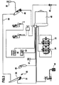
- An internal combustion engine 20 such as, for example, is used to drive the vehicle a diesel engine that drives a hydraulic pump. It can be used for the front axle 12 a first hydraulic pump 22 and for the rear axle 14 a second hydraulic pump 24 may be provided (FIG. 3) or only one only hydraulic pump.
- Hydraulic pumps 22 and 24 drive one or more hydraulic motors Hydromotor) on (not shown in the drawing), which for example a drives mechanical transmission with drive elements, via which accordingly the front axle 12 and the rear axle 14 can be driven. It can also wheel motors can be provided as hydraulic motors, which the wheels 16, 18 drive directly.
- Hydromotor Hydromotor
- the internal combustion engine 20 also has a front Power take-off 26 and a rear power take-off 28 drives. These power take-offs 26, 28 are connected to the internal combustion engine via a power take-off clutch 20 connectable.
- Additional devices can be mounted on the chassis 10 of the vehicle either via the front power take-off 26 or the rear power take-off 28 can be driven.
- the vehicle shown in FIGS. 1 and 2 there is one Snow blower 30 mounted on a front of the chassis 10 and over the front power take-off 26 driven.
- the vehicle is steered conventionally via a steering wheel 32.
- the internal combustion engine is controlled via an accelerator pedal 34 and in particular a foot pedal.
- the accelerator pedal 34 then acts as an accelerator pedal.
- There is also a hand throttle 36 is provided, via which the internal combustion engine 20 accordingly is controllable, i.e. the engine speed meets the corresponding requirements, especially an additional device, is adaptable.
- the individual driving states of the vehicle are controlled by the driver Program selector switch 38 adjustable, via which certain driving modes can be set are. For choosing the direction of travel and in particular for switching There is a travel selector lever between forward and reverse travel 40 provided. Instead of this travel direction preselection lever 40 an additional toggle switch is provided on the program selector switch 38 be so that in every driving mode between driving forward and driving backwards (and zero position) is switchable.
- a reset pedal 44 (inching pedal) is also provided.
- the vehicle according to the invention comprises an electronic control 46 ( Figure 3), which has a process computer and a programmable memory the controller 46 being connected to a position transmitter, which is the respective position of an actuating device for controlling the delivery volume the hydraulic pump detects and the control a maximum parameter transmitted.
- the controller controls one in the Stored program and the maximum parameter transmitted Delivery volume of the hydraulic pump. A corresponding control is also described in DE 41 11 921 A1, to which reference is made in full becomes.
- a tachometer 49 determines the actual value of the speed of the internal combustion engine and supplies this value to the controller 46.
- driving modes P1, P2, P3 and P4 are provided, whereby the respective driving mode is adjustable with the program selector switch 38.
- the program modes P1 and P2 which are road travel modes (P1 for fast road travel and P2 for slow road travel), for example the speed control via the accelerator pedal 34 as an accelerator pedal.
- the accelerator pedal 34 thereby forms a first actuating device with which the internal combustion engine 20 is controllable.
- the engine speed of the internal combustion engine 20 can be controlled via the accelerator pedal 34 and possibly additionally the delivery volume of the hydraulic pump or Adjust hydraulic pumps 22, 24.
- P1, P2 then begins to pivot the hydraulic pump 22 or 24, for example, that is to drive the associated hydraulic motor, if one determined starting speed as the speed of the internal combustion engine 20 or a certain approach point is reached via the position of the foot pedal 34.
- a certain break point which is defined by the fact that the Hydraulic pump 22 or 24 a certain delivery volume is reached made sure that the delivery volume of the pump to the maximum Funding volume can be increased.
- the break point is, for example at about 20% of the funding volume in relation to the maximum Delivery volume.
- the vehicle can be operated in the manner of a operate conventional vehicles with automatic transmission, the Return pedal 44 (inch pedal) acts as a brake and clutch and the accelerator pedal 34 as an accelerator pedal.
- a work mode P3 the speed of the vehicle alone is over the delivery volume of the hydraulic pump 22 or 24 controlled. This is about the hand throttle lever 36 a target engine speed in particular for the over Power take-off 26 or 28 driven auxiliary device via the hand throttle lever 36 set.
- a motor speed potentiometer 48 is adjusted accordingly, so that the setpoint can be transmitted to the controller 46.
- the speed of the vehicle is then, for example, manually operable Potentiometer 37 set.
- a first actuating device is formed, via which the delivery volume in working mode P3 the hydraulic pump 22 or 24 is controllable.
- One is in particular Proportional control is provided, in which the delivery volume is proportional to the position and in particular the rotational position of the hand throttle lever.
- controller 46 compares the actual value of the engine speed (measured via the speed sensor 49) with the setpoint. Is the engine speed of the internal combustion engine 20 is smaller than one corresponding to the break point Speed, then the control of the delivery volume of the Hydraulic pump 22 or 24 blocked via the first actuating device 36. is correspondingly the potentiometer 37 in a position which corresponds to a delivery volume below the break point, then the control is over this potentiometer 37 locked.
- the engine speed drops during control below a target starting speed or the first actuating device in brought such a position that the delivery volume of the hydraulic pump 22nd or 24 falls below the break point, then the first actuating device is also blocked.
- a second actuating device 50 is now provided, which via a switch and in particular the program selector switch 38 (FIG. 2) can be activated in work mode P4.
- the working mode P4 corresponds in terms of the drive control of the vehicle the work mode P3, only that the Control of the delivery volume of the hydraulic pump via the second control device 50 instead of via the first actuating device 37.
- a driver can for the work mode decide whether to use the speed control the first actuating device with potentiometer 37 or the second actuating device 50 wants to perform.
- the second actuating device 50 can be used the delivery volume of the hydraulic pump 22 or 24 with a fixed setting Control the target speed of the internal combustion engine 20. For this purpose, it includes a potentiometer 51, which is coupled to the accelerator pedal 34.
- the second actuating device 50 is coupled to the accelerator pedal 34 such that actuation / release of the accelerator pedal 34 the speed when the second actuating device 50 is activated can control the vehicle via the control of the delivery volume.
- the driver must, in order to a certain volume (corresponding to a certain speed), provided the second actuating device 50 activated, leave your foot on the accelerator pedal 34. By further depressing he can reach a higher speed. Alternatively it is possible to activate the first actuating device 37. Here is a constant hold on not necessary if maintaining a certain speed shall be.
- a driver can therefore decide whether, depending on the activation of the first actuating device 37 or the second adjusting device 50 a constant speed by hand or using the accelerator pedal 34.
- the second actuating device 50 is connected to the controller 46 is coupled for a limit load control. If the position of the accelerator pedal 34 is that the delivery volume of the hydraulic pump 22 or 24 below the If the point of inflection lies, then the second actuating device 50 is deactivated because it is unsuitable Conditions for the work mode exist.
- a blocking device 54 with a switch 55 can also be provided which wheels 16 of the front axle 12 or wheels 18 of the rear axle 14 with one another can be coupled in order to drive them at the same speed.
- open Locking device are the wheels 16 and 18 with any speed differences drivable, with a mechanical connecting element for the Coupling ensures.
- the accelerator pedal 34 is with an element which actuates the potentiometer 48 mechanically connected, for example via a Bowden cable 58. This mechanical connection is effective in road driving mode P1 or P2 to be able to control the engine speed accordingly.
Landscapes
- Engineering & Computer Science (AREA)
- Mechanical Engineering (AREA)
- General Engineering & Computer Science (AREA)
- Chemical & Material Sciences (AREA)
- Combustion & Propulsion (AREA)
- Transportation (AREA)
- Automation & Control Theory (AREA)
- Control Of Fluid Gearings (AREA)
- Control Of Vehicle Engines Or Engines For Specific Uses (AREA)
- Control Of Transmission Device (AREA)
Abstract
Description
- Figur 1
- eine Seitenansicht eines Ausführungsbeispiels eines erfindungsgemäßen Fahrzeugs (in diesem Fall eines Kommunalfahrzeugs mit Nebenabtrieben);
- Figur 2
- eine Draufsicht auf das Fahrzeug gemäß Figur 1 mit offenem Dach, und
- Figur 3
- schematisch ein Ausführungsbeispiel eines Hydraulik- und Steuerungsschemas.
Claims (14)
- Fahrzeug, insbesondere Zugfahrzeug oder Fahrzeug mit Nebenabtrieb (26; 28), umfassend einen Verbrennungsmotor (20), mindestens eine von dem Verbrennungsmotor (20) angetriebene Hydraulikpumpe (22; 24) mit steuerbarem Fördervolumen, mindestens einen Hydromotor, welcher von der mindestens einen Hydraulikpumpe (22; 24) angetrieben ist, wobei ein Hydromotor ein oder mehrere Antriebselemente des Fahrzeugs antreibt, ein vom Fahrer betätigbares Fahrpedal (34) zur Einstellung der Drehzahl des Verbrennungsmotors (20) in einem Straßenfahrt-Modus (P1; P2) und eine vom Fahrer betätigbare erste Stelleinrichtung (36) zur Steuerung des Fördervolumens der Hydraulikpumpe (22; 24) in einem Arbeits-Modus (P3),
dadurch gekennzeichnet, daß eine zweite Stelleinrichtung (50) an das Fahrpedal (34) gekoppelt ist und über das Fahrpedal (34) betätigbar ist, und mit der im Arbeits-Modus (P4) das Fördervolumen der Hydraulikpumpe (22; 24) steuerbar ist. - Fahrzeug nach Anspruch 1, dadurch gekennzeichnet, daß ein Schalter (38) vorgesehen ist, mit dem vom Fahrer entweder die erste Stelleinrichtung (37) oder die zweite Stelleinrichtung (50) zur Steuerung des Fördervolumens der Hydraulikpumpe (22; 24) im Arbeits-Modus (P3; P4) aktivierbar ist.
- Fahrzeug nach Anspruch 1 oder 2, dadurch gekennzeichnet, daß die erste Stelleinrichtung ein Potentiometer (37) umfaßt.
- Fahrzeug nach einem der vorangehenden Ansprüche, dadurch gekennzeichnet, daß die zweite Stelleinrichtung ein über das Fahrpedal (34) betätigbares Potentiometer (51) umfaßt.
- Fahrzeug nach einem der vorangehenden Ansprüche, dadurch gekennzeichnet, daß im Arbeits-Modus (P3; P4) das Fördervolumen der Hydraulikpumpe (22; 24) proportional zur Stellung der aktivierten Stelleinrichtung (37; 50) eingestellt ist.
- Fahrzeug nach einem der vorangehenden Ansprüche, dadurch gekennzeichnet, daß im Straßenfahrt-Modus (P1, P2) das Fahrpedal (34) als Gaspedal für den Verbrennungsmotor (20) wirkt.
- Fahrzeug nach einem der vorangehenden Ansprüche, dadurch gekennzeichnet, daß im Arbeits-Modus (P4) bei aktivierter zweiter Stelleinrichtung (50) das Fahrpedal (34) als Steuerpedal für das Fördervolumen der Hydraulikpumpe (22; 24) wirkt.
- Fahrzeug nach einem der vorangehenden Ansprüche, dadurch gekennzeichnet, daß im Arbeits-Modus (P3; P4) eine Motordrehzahl des Verbrennungsmotors (20) fest eingestellt ist.
- Fahrzeug nach einem der vorangehenden Ansprüche, dadurch gekennzeichnet, daß die zweite Stelleinrichtung (50) an eine Steuerung (26) gekoppelt ist, welche den oder die Antriebe des Fahrzeugs steuert und/oder regelt.
- Fahrzeug nach Anspruch 9, dadurch gekennzeichnet, daß die zweite Stelleinrichtung (50) über eine Grenzlastregelung für den Verbrennungsmotor (20) deaktivierbar ist.
- Fahrzeug nach Anspruch 9 oder 10, dadurch gekennzeichnet, daß bei einer Motordrehzahl des Verbrennungsmotors (20) unterhalb einer Anfahr-Solldrehzahl die zweite Stelleinrichtung (50) deaktiviert ist.
- Fahrzeug nach einem der Ansprüche 9 bis 11, dadurch gekennzeichnet, daß bei Erreichen einer Stellung der zweiten Stelleinrichtung (50), welche einem Fördervolumen unterhalb eines Knickpunkts der Hydraulikpumpe (22; 24) entspricht, die zweite Stelleinrichtung (50) deaktiviert ist oder wird.
- Fahrzeug nach einem der vorangehenden Ansprüche, dadurch gekennzeichnet, daß im Straßenfahrt-Modus (P1; P2) die zweite Stelleinrichtung (50) deaktiviert ist.
- Fahrzeug nach einem der vorangehenden Ansprüche, dadurch gekennzeichnet, daß im Straßenfahrt-Modus (P1; P2) die erste Stelleinrichtung (36) deaktiviert ist.
Applications Claiming Priority (2)
| Application Number | Priority Date | Filing Date | Title |
|---|---|---|---|
| DE10310980 | 2003-03-07 | ||
| DE10310980A DE10310980B3 (de) | 2003-03-07 | 2003-03-07 | Fahrzeug |
Publications (3)
| Publication Number | Publication Date |
|---|---|
| EP1455119A2 true EP1455119A2 (de) | 2004-09-08 |
| EP1455119A3 EP1455119A3 (de) | 2010-12-08 |
| EP1455119B1 EP1455119B1 (de) | 2011-12-28 |
Family
ID=32049681
Family Applications (1)
| Application Number | Title | Priority Date | Filing Date |
|---|---|---|---|
| EP04005456A Expired - Lifetime EP1455119B1 (de) | 2003-03-07 | 2004-03-08 | Fahrzeug mit hydrostatischem Getriebe |
Country Status (3)
| Country | Link |
|---|---|
| EP (1) | EP1455119B1 (de) |
| AT (1) | ATE538983T1 (de) |
| DE (1) | DE10310980B3 (de) |
Cited By (3)
| Publication number | Priority date | Publication date | Assignee | Title |
|---|---|---|---|---|
| GB2531766A (en) * | 2014-10-29 | 2016-05-04 | Bamford Excavators Ltd | Working Machine |
| US9469290B2 (en) | 2012-08-16 | 2016-10-18 | Cnh Industrial America Llc | Power/economy mode control system for an agricultural vehicle |
| US10119247B2 (en) | 2014-10-29 | 2018-11-06 | J. C. Bamford Excavators Limited | Working machine |
Families Citing this family (3)
| Publication number | Priority date | Publication date | Assignee | Title |
|---|---|---|---|---|
| GB2420168A (en) * | 2004-11-16 | 2006-05-17 | Agco Gmbh & Co | Hydraulic transmission with bypass 'clutch' valve |
| DE102012020984A1 (de) | 2012-10-25 | 2014-04-30 | Liebherr-Hydraulikbagger Gmbh | Vorrichtung zur Fahrgeschwindigkeitssteuerung/-regelung eines Arbeitsfahrzeugs und Verfahren hierzu |
| DE102017219997A1 (de) * | 2017-11-10 | 2019-05-16 | Zf Friedrichshafen Ag | Verfahren zur Steuerung eines für ein land- oder bauwirtschaftlich nutzbares Arbeitsfahrzeug vorgesehenen Fahrantriebes sowie Nebenabtriebes und Steuereinrichtung derselben |
Citations (2)
| Publication number | Priority date | Publication date | Assignee | Title |
|---|---|---|---|---|
| DE4111921A1 (de) | 1991-04-12 | 1992-10-15 | Holder Gmbh & Co Geb | Fahrzeug |
| DE19539043A1 (de) | 1995-10-20 | 1997-04-24 | Holder Gmbh & Co Geb | Hydrostatisch angetriebenes Fahrzeug |
Family Cites Families (4)
| Publication number | Priority date | Publication date | Assignee | Title |
|---|---|---|---|---|
| DE2362221A1 (de) * | 1973-12-14 | 1975-06-19 | Kloeckner Humboldt Deutz Ag | Steuereinrichtung fuer ein aus einer brennkraftmaschine und einem hydrostatischen getriebe gebildetes antriebsaggregat |
| GB2234328B (en) * | 1989-07-12 | 1993-09-08 | Johnston Eng Ltd | Improvements in vehicle control systems |
| EP0967107B1 (de) * | 1998-06-25 | 2001-09-19 | ZF FRIEDRICHSHAFEN Aktiengesellschaft | Verfahren zum Steuern einer Fahrzeugantriebseinheit mit stufenlos verstellbarem Getriebe |
| DE19921697A1 (de) * | 1999-05-12 | 2000-11-16 | Claas Selbstfahr Erntemasch | Verfahren und Vorrichtung zur Drehzahlvorgabe an einen Antriebsmotor an einer Arbeitsmaschine |
-
2003
- 2003-03-07 DE DE10310980A patent/DE10310980B3/de not_active Expired - Fee Related
-
2004
- 2004-03-08 EP EP04005456A patent/EP1455119B1/de not_active Expired - Lifetime
- 2004-03-08 AT AT04005456T patent/ATE538983T1/de active
Patent Citations (2)
| Publication number | Priority date | Publication date | Assignee | Title |
|---|---|---|---|---|
| DE4111921A1 (de) | 1991-04-12 | 1992-10-15 | Holder Gmbh & Co Geb | Fahrzeug |
| DE19539043A1 (de) | 1995-10-20 | 1997-04-24 | Holder Gmbh & Co Geb | Hydrostatisch angetriebenes Fahrzeug |
Cited By (8)
| Publication number | Priority date | Publication date | Assignee | Title |
|---|---|---|---|---|
| US9469290B2 (en) | 2012-08-16 | 2016-10-18 | Cnh Industrial America Llc | Power/economy mode control system for an agricultural vehicle |
| GB2531766A (en) * | 2014-10-29 | 2016-05-04 | Bamford Excavators Ltd | Working Machine |
| US20160121722A1 (en) * | 2014-10-29 | 2016-05-05 | J. C. Bamford Excavators Limited | Working Machine |
| KR20160052392A (ko) * | 2014-10-29 | 2016-05-12 | 제이씨 뱀포드 엑스카베이터즈 리미티드 | 작업 기계 |
| US9994105B2 (en) | 2014-10-29 | 2018-06-12 | J. C. Bamford Excavators Limited | Working machine |
| US10119247B2 (en) | 2014-10-29 | 2018-11-06 | J. C. Bamford Excavators Limited | Working machine |
| US11111649B2 (en) | 2014-10-29 | 2021-09-07 | J. C. Bamford Excavators Limited | Working machine |
| KR102536756B1 (ko) | 2014-10-29 | 2023-05-25 | 제이씨 뱀포드 엑스카베이터즈 리미티드 | 작업 기계 |
Also Published As
| Publication number | Publication date |
|---|---|
| EP1455119A3 (de) | 2010-12-08 |
| EP1455119B1 (de) | 2011-12-28 |
| ATE538983T1 (de) | 2012-01-15 |
| DE10310980B3 (de) | 2004-04-29 |
Similar Documents
| Publication | Publication Date | Title |
|---|---|---|
| EP1177114B1 (de) | Vorrichtung und verfahren zum verändern der ist-geschwindigkeit eines arbeitsfahrzeuges mit stufenlosgetriebe und tempomatfunktion | |
| EP1743823B1 (de) | Antriebssystem eines Arbeitsfahrzeugs | |
| DE69106143T2 (de) | Einrichtung und verfahren zum bedienen eines fahrzeugantriebs und dessen anordnung. | |
| EP1052388B1 (de) | Verfahren zur Drehzahlvorgabe an einem Antriebsmotor an einer Arbeitsmaschine | |
| EP1268231B1 (de) | Rangiermodus bei fahrzeugen mit automatisierter kupplung | |
| EP0947414B1 (de) | Lenksteuersystem für Raupenfahrzeug | |
| DE602005002867T2 (de) | Kontrollsystem, insbesondere für einen Traktor | |
| DE4420116A1 (de) | Retardersteuerung | |
| EP1350658A1 (de) | Antriebssystem eines Arbeitsfahrzeugs | |
| DE2522719A1 (de) | Getriebesteuereinrichtung | |
| DE3928670C2 (de) | Geschwindigkeitsregeleinrichtung für ein Fahrzeug | |
| DE69302797T2 (de) | Steuervorrichtung für ein automatisiertes Getriebe eines Nutzfahrzeuges | |
| EP1236933B1 (de) | Antriebssystem eines Arbeitsfahrzeugs | |
| EP2434133A1 (de) | Motorsteuerungskonzept und Vorrichtung zum Steuern der Leistung eines Motorfahrzeugs | |
| EP1455119B1 (de) | Fahrzeug mit hydrostatischem Getriebe | |
| DE4219050C2 (de) | Bedienungsoberfläche für die Ansteuerung einer Antriebsmaschine und eines stufenlos verstellbaren Getriebes | |
| DE4111921C2 (de) | Fahrzeug | |
| DE69304303T2 (de) | Verfahren und einrichtung zur fahrzeuggeschwindigkeitsregelung | |
| EP1484213B1 (de) | Verfahren und Vorrichtung zur Regelung der Fahrgeschwindigkeit eines Kraftfahrzeugs | |
| DE10214598B4 (de) | Fahrantrieb für eine landwirtschaftliche Erntemaschine mit Steuerung der Fahrgeschwindigkeit bei Straßenfahrten | |
| DE69821944T2 (de) | Verfahren zur Steuerung eines Verbrennungsmotors | |
| DE3245518C2 (de) | Steuersystem für eine Antriebsvorrichtung für landwirtschaftliche Zugmaschinen | |
| DE102016220005A1 (de) | Geschwindigkeitssteuermechanismus für ein Fahrzeug | |
| WO2002102647A1 (de) | Motorgerät | |
| DE1455804B2 (de) | Steuereinrichtung fur die An tnebs und die Bremsleistung einer mit einem stufenlos verstellbaren Getriebe kombinierten Antnebsma schme fur Fahrzeuge |
Legal Events
| Date | Code | Title | Description |
|---|---|---|---|
| PUAI | Public reference made under article 153(3) epc to a published international application that has entered the european phase |
Free format text: ORIGINAL CODE: 0009012 |
|
| AK | Designated contracting states |
Kind code of ref document: A2 Designated state(s): AT BE BG CH CY CZ DE DK EE ES FI FR GB GR HU IE IT LI LU MC NL PL PT RO SE SI SK TR |
|
| AX | Request for extension of the european patent |
Extension state: AL LT LV MK |
|
| RAP1 | Party data changed (applicant data changed or rights of an application transferred) |
Owner name: HOLDER INDUSTRIES GMBH |
|
| PUAL | Search report despatched |
Free format text: ORIGINAL CODE: 0009013 |
|
| AK | Designated contracting states |
Kind code of ref document: A3 Designated state(s): AT BE BG CH CY CZ DE DK EE ES FI FR GB GR HU IE IT LI LU MC NL PL PT RO SE SI SK TR |
|
| AX | Request for extension of the european patent |
Extension state: AL LT LV MK |
|
| REG | Reference to a national code |
Ref country code: DE Ref legal event code: R079 Ref document number: 502004013178 Country of ref document: DE Free format text: PREVIOUS MAIN CLASS: F16H0061420000 Ipc: B60W0030180000 |
|
| 17P | Request for examination filed |
Effective date: 20110601 |
|
| GRAP | Despatch of communication of intention to grant a patent |
Free format text: ORIGINAL CODE: EPIDOSNIGR1 |
|
| RIC1 | Information provided on ipc code assigned before grant |
Ipc: B60W 10/30 20060101ALN20110705BHEP Ipc: B60W 10/10 20060101ALN20110705BHEP Ipc: B60W 30/18 20060101AFI20110705BHEP |
|
| AKX | Designation fees paid |
Designated state(s): AT BE BG CH CY CZ DE DK EE ES FI FR GB GR HU IE IT LI LU MC NL PL PT RO SE SI SK TR |
|
| GRAS | Grant fee paid |
Free format text: ORIGINAL CODE: EPIDOSNIGR3 |
|
| GRAA | (expected) grant |
Free format text: ORIGINAL CODE: 0009210 |
|
| AK | Designated contracting states |
Kind code of ref document: B1 Designated state(s): AT BE BG CH CY CZ DE DK EE ES FI FR GB GR HU IE IT LI LU MC NL PL PT RO SE SI SK TR |
|
| REG | Reference to a national code |
Ref country code: GB Ref legal event code: FG4D Free format text: NOT ENGLISH |
|
| REG | Reference to a national code |
Ref country code: CH Ref legal event code: EP |
|
| REG | Reference to a national code |
Ref country code: AT Ref legal event code: REF Ref document number: 538983 Country of ref document: AT Kind code of ref document: T Effective date: 20120115 |
|
| REG | Reference to a national code |
Ref country code: IE Ref legal event code: FG4D |
|
| REG | Reference to a national code |
Ref country code: CH Ref legal event code: PFA Owner name: MAX HOLDER GMBH Free format text: HOLDER INDUSTRIES GMBH#MAX-HOLDER-STRASSE 1#72555 METZINGEN (DE) -TRANSFER TO- MAX HOLDER GMBH#MAX-HOLDER-STR. 1#72555 METZINGEN (DE) Ref country code: CH Ref legal event code: NV Representative=s name: ISLER & PEDRAZZINI AG |
|
| RAP2 | Party data changed (patent owner data changed or rights of a patent transferred) |
Owner name: MAX HOLDER GMBH |
|
| REG | Reference to a national code |
Ref country code: DE Ref legal event code: R096 Ref document number: 502004013178 Country of ref document: DE Effective date: 20120308 |
|
| REG | Reference to a national code |
Ref country code: NL Ref legal event code: VDEP Effective date: 20111228 |
|
| PG25 | Lapsed in a contracting state [announced via postgrant information from national office to epo] |
Ref country code: GR Free format text: LAPSE BECAUSE OF FAILURE TO SUBMIT A TRANSLATION OF THE DESCRIPTION OR TO PAY THE FEE WITHIN THE PRESCRIBED TIME-LIMIT Effective date: 20120329 Ref country code: SI Free format text: LAPSE BECAUSE OF FAILURE TO SUBMIT A TRANSLATION OF THE DESCRIPTION OR TO PAY THE FEE WITHIN THE PRESCRIBED TIME-LIMIT Effective date: 20111228 Ref country code: SE Free format text: LAPSE BECAUSE OF FAILURE TO SUBMIT A TRANSLATION OF THE DESCRIPTION OR TO PAY THE FEE WITHIN THE PRESCRIBED TIME-LIMIT Effective date: 20111228 |
|
| PG25 | Lapsed in a contracting state [announced via postgrant information from national office to epo] |
Ref country code: CY Free format text: LAPSE BECAUSE OF FAILURE TO SUBMIT A TRANSLATION OF THE DESCRIPTION OR TO PAY THE FEE WITHIN THE PRESCRIBED TIME-LIMIT Effective date: 20111228 |
|
| REG | Reference to a national code |
Ref country code: IE Ref legal event code: FD4D |
|
| PG25 | Lapsed in a contracting state [announced via postgrant information from national office to epo] |
Ref country code: EE Free format text: LAPSE BECAUSE OF FAILURE TO SUBMIT A TRANSLATION OF THE DESCRIPTION OR TO PAY THE FEE WITHIN THE PRESCRIBED TIME-LIMIT Effective date: 20111228 Ref country code: NL Free format text: LAPSE BECAUSE OF FAILURE TO SUBMIT A TRANSLATION OF THE DESCRIPTION OR TO PAY THE FEE WITHIN THE PRESCRIBED TIME-LIMIT Effective date: 20111228 Ref country code: CZ Free format text: LAPSE BECAUSE OF FAILURE TO SUBMIT A TRANSLATION OF THE DESCRIPTION OR TO PAY THE FEE WITHIN THE PRESCRIBED TIME-LIMIT Effective date: 20111228 Ref country code: BG Free format text: LAPSE BECAUSE OF FAILURE TO SUBMIT A TRANSLATION OF THE DESCRIPTION OR TO PAY THE FEE WITHIN THE PRESCRIBED TIME-LIMIT Effective date: 20120328 Ref country code: SK Free format text: LAPSE BECAUSE OF FAILURE TO SUBMIT A TRANSLATION OF THE DESCRIPTION OR TO PAY THE FEE WITHIN THE PRESCRIBED TIME-LIMIT Effective date: 20111228 Ref country code: IE Free format text: LAPSE BECAUSE OF FAILURE TO SUBMIT A TRANSLATION OF THE DESCRIPTION OR TO PAY THE FEE WITHIN THE PRESCRIBED TIME-LIMIT Effective date: 20111228 |
|
| PG25 | Lapsed in a contracting state [announced via postgrant information from national office to epo] |
Ref country code: PT Free format text: LAPSE BECAUSE OF FAILURE TO SUBMIT A TRANSLATION OF THE DESCRIPTION OR TO PAY THE FEE WITHIN THE PRESCRIBED TIME-LIMIT Effective date: 20120430 Ref country code: RO Free format text: LAPSE BECAUSE OF FAILURE TO SUBMIT A TRANSLATION OF THE DESCRIPTION OR TO PAY THE FEE WITHIN THE PRESCRIBED TIME-LIMIT Effective date: 20111228 Ref country code: PL Free format text: LAPSE BECAUSE OF FAILURE TO SUBMIT A TRANSLATION OF THE DESCRIPTION OR TO PAY THE FEE WITHIN THE PRESCRIBED TIME-LIMIT Effective date: 20111228 |
|
| BERE | Be: lapsed |
Owner name: HOLDER INDUSTRIES G.M.B.H. Effective date: 20120331 |
|
| REG | Reference to a national code |
Ref country code: DE Ref legal event code: R082 Ref document number: 502004013178 Country of ref document: DE Representative=s name: HOEGER, STELLRECHT & PARTNER PATENTANWAELTE, DE |
|
| PG25 | Lapsed in a contracting state [announced via postgrant information from national office to epo] |
Ref country code: DK Free format text: LAPSE BECAUSE OF FAILURE TO SUBMIT A TRANSLATION OF THE DESCRIPTION OR TO PAY THE FEE WITHIN THE PRESCRIBED TIME-LIMIT Effective date: 20111228 Ref country code: MC Free format text: LAPSE BECAUSE OF NON-PAYMENT OF DUE FEES Effective date: 20120331 |
|
| PLBE | No opposition filed within time limit |
Free format text: ORIGINAL CODE: 0009261 |
|
| STAA | Information on the status of an ep patent application or granted ep patent |
Free format text: STATUS: NO OPPOSITION FILED WITHIN TIME LIMIT |
|
| REG | Reference to a national code |
Ref country code: AT Ref legal event code: HC Ref document number: 538983 Country of ref document: AT Kind code of ref document: T Owner name: MAX HOLDER GMBH, DE Effective date: 20120924 |
|
| GBPC | Gb: european patent ceased through non-payment of renewal fee |
Effective date: 20120328 |
|
| PG25 | Lapsed in a contracting state [announced via postgrant information from national office to epo] |
Ref country code: IT Free format text: LAPSE BECAUSE OF FAILURE TO SUBMIT A TRANSLATION OF THE DESCRIPTION OR TO PAY THE FEE WITHIN THE PRESCRIBED TIME-LIMIT Effective date: 20111228 |
|
| 26N | No opposition filed |
Effective date: 20121001 |
|
| REG | Reference to a national code |
Ref country code: DE Ref legal event code: R081 Ref document number: 502004013178 Country of ref document: DE Owner name: MAX HOLDER GMBH, DE Free format text: FORMER OWNER: GEBRUEDER HOLDER GMBH, 72555 METZINGEN, DE Effective date: 20120116 Ref country code: DE Ref legal event code: R082 Ref document number: 502004013178 Country of ref document: DE Representative=s name: , Effective date: 20121029 Ref country code: DE Ref legal event code: R081 Ref document number: 502004013178 Country of ref document: DE Owner name: MAX HOLDER GMBH, DE Free format text: FORMER OWNER: HOLDER INDUSTRIES GMBH, 72555 METZINGEN, DE Effective date: 20121029 Ref country code: DE Ref legal event code: R082 Ref document number: 502004013178 Country of ref document: DE Representative=s name: HOEGER, STELLRECHT & PARTNER PATENTANWAELTE, DE Effective date: 20121029 Ref country code: DE Ref legal event code: R082 Ref document number: 502004013178 Country of ref document: DE Representative=s name: KOHLER SCHMID MOEBUS, DE Effective date: 20121029 Ref country code: DE Ref legal event code: R082 Ref document number: 502004013178 Country of ref document: DE Representative=s name: KOHLER SCHMID MOEBUS PATENTANWAELTE PARTNERSCH, DE Effective date: 20121029 |
|
| REG | Reference to a national code |
Ref country code: DE Ref legal event code: R097 Ref document number: 502004013178 Country of ref document: DE Effective date: 20121001 |
|
| PG25 | Lapsed in a contracting state [announced via postgrant information from national office to epo] |
Ref country code: BE Free format text: LAPSE BECAUSE OF NON-PAYMENT OF DUE FEES Effective date: 20120331 Ref country code: GB Free format text: LAPSE BECAUSE OF NON-PAYMENT OF DUE FEES Effective date: 20120328 |
|
| PG25 | Lapsed in a contracting state [announced via postgrant information from national office to epo] |
Ref country code: ES Free format text: LAPSE BECAUSE OF FAILURE TO SUBMIT A TRANSLATION OF THE DESCRIPTION OR TO PAY THE FEE WITHIN THE PRESCRIBED TIME-LIMIT Effective date: 20120408 |
|
| REG | Reference to a national code |
Ref country code: DE Ref legal event code: R082 Ref document number: 502004013178 Country of ref document: DE Representative=s name: KOHLER SCHMID MOEBUS, DE Ref country code: DE Ref legal event code: R082 Ref document number: 502004013178 Country of ref document: DE Representative=s name: KOHLER SCHMID MOEBUS PATENTANWAELTE PARTNERSCH, DE Ref country code: DE Ref legal event code: R082 Ref document number: 502004013178 Country of ref document: DE Representative=s name: , |
|
| PG25 | Lapsed in a contracting state [announced via postgrant information from national office to epo] |
Ref country code: FI Free format text: LAPSE BECAUSE OF FAILURE TO SUBMIT A TRANSLATION OF THE DESCRIPTION OR TO PAY THE FEE WITHIN THE PRESCRIBED TIME-LIMIT Effective date: 20111228 |
|
| PG25 | Lapsed in a contracting state [announced via postgrant information from national office to epo] |
Ref country code: TR Free format text: LAPSE BECAUSE OF FAILURE TO SUBMIT A TRANSLATION OF THE DESCRIPTION OR TO PAY THE FEE WITHIN THE PRESCRIBED TIME-LIMIT Effective date: 20111228 |
|
| PG25 | Lapsed in a contracting state [announced via postgrant information from national office to epo] |
Ref country code: LU Free format text: LAPSE BECAUSE OF NON-PAYMENT OF DUE FEES Effective date: 20120308 |
|
| PG25 | Lapsed in a contracting state [announced via postgrant information from national office to epo] |
Ref country code: HU Free format text: LAPSE BECAUSE OF FAILURE TO SUBMIT A TRANSLATION OF THE DESCRIPTION OR TO PAY THE FEE WITHIN THE PRESCRIBED TIME-LIMIT Effective date: 20040308 |
|
| REG | Reference to a national code |
Ref country code: FR Ref legal event code: PLFP Year of fee payment: 13 |
|
| REG | Reference to a national code |
Ref country code: FR Ref legal event code: PLFP Year of fee payment: 14 |
|
| REG | Reference to a national code |
Ref country code: FR Ref legal event code: PLFP Year of fee payment: 15 |
|
| PGFP | Annual fee paid to national office [announced via postgrant information from national office to epo] |
Ref country code: DE Payment date: 20200108 Year of fee payment: 17 Ref country code: AT Payment date: 20200319 Year of fee payment: 17 |
|
| PGFP | Annual fee paid to national office [announced via postgrant information from national office to epo] |
Ref country code: CH Payment date: 20200211 Year of fee payment: 17 |
|
| PGFP | Annual fee paid to national office [announced via postgrant information from national office to epo] |
Ref country code: FR Payment date: 20200324 Year of fee payment: 17 |
|
| REG | Reference to a national code |
Ref country code: DE Ref legal event code: R119 Ref document number: 502004013178 Country of ref document: DE |
|
| REG | Reference to a national code |
Ref country code: CH Ref legal event code: PL |
|
| REG | Reference to a national code |
Ref country code: AT Ref legal event code: MM01 Ref document number: 538983 Country of ref document: AT Kind code of ref document: T Effective date: 20210308 |
|
| PG25 | Lapsed in a contracting state [announced via postgrant information from national office to epo] |
Ref country code: CH Free format text: LAPSE BECAUSE OF NON-PAYMENT OF DUE FEES Effective date: 20210331 Ref country code: AT Free format text: LAPSE BECAUSE OF NON-PAYMENT OF DUE FEES Effective date: 20210308 Ref country code: LI Free format text: LAPSE BECAUSE OF NON-PAYMENT OF DUE FEES Effective date: 20210331 Ref country code: DE Free format text: LAPSE BECAUSE OF NON-PAYMENT OF DUE FEES Effective date: 20211001 Ref country code: FR Free format text: LAPSE BECAUSE OF NON-PAYMENT OF DUE FEES Effective date: 20210331 |