EP1454869B1 - Passenger conveyor - Google Patents
Passenger conveyor Download PDFInfo
- Publication number
- EP1454869B1 EP1454869B1 EP01274915A EP01274915A EP1454869B1 EP 1454869 B1 EP1454869 B1 EP 1454869B1 EP 01274915 A EP01274915 A EP 01274915A EP 01274915 A EP01274915 A EP 01274915A EP 1454869 B1 EP1454869 B1 EP 1454869B1
- Authority
- EP
- European Patent Office
- Prior art keywords
- stairs
- balustrade
- slope
- handrail
- moving
- Prior art date
- Legal status (The legal status is an assumption and is not a legal conclusion. Google has not performed a legal analysis and makes no representation as to the accuracy of the status listed.)
- Expired - Lifetime
Links
Images


Classifications
-
- B—PERFORMING OPERATIONS; TRANSPORTING
- B66—HOISTING; LIFTING; HAULING
- B66B—ELEVATORS; ESCALATORS OR MOVING WALKWAYS
- B66B23/00—Component parts of escalators or moving walkways
- B66B23/22—Balustrades
- B66B23/225—Lighting systems therefor
-
- B—PERFORMING OPERATIONS; TRANSPORTING
- B66—HOISTING; LIFTING; HAULING
- B66B—ELEVATORS; ESCALATORS OR MOVING WALKWAYS
- B66B23/00—Component parts of escalators or moving walkways
- B66B23/02—Driving gear
- B66B23/026—Driving gear with a drive or carrying sprocket wheel located at end portions
Definitions
- the present invention relates to a passenger conveyor such as an escalator, an electrically operated road and the like, and more particularly to a passenger conveyor which is preferably placed in a narrow place.
- the former of the prior arts mentioned above has an advantage that the width can be made narrower at a degree by which extra drive chain and drive sprocket for power transmission can be omitted by directly driving the stairs and the stairs chain by the electric motor.
- the latter of the prior arts can make the passenger to get on the passenger conveyor on the safe side in a point that it is possible to reduce a change that the baggage of the passenger hits the balustrade panel.
- the baggage hits the step portion such as a back side of a member guiding the moving handrail or the like, and there is a problem that an overturning trouble of the passenger is brought about.
- JP-A-2001 139 273 discloses a passenger conveyor with the features of the pre-characterizing portion of Claim 1. Another related passenger conveyor is disclosed in US-A-5 135 097 .
- An object of the present invention is to provide a passenger conveyor which can sufficiently reduce a width.
- Another object of the present invention is to provide a passenger conveyor on which a passenger can get with slowing down even in the case that a width is reduced, and a baggage or the like can be prevented from hitting a back side of a member for guiding a moving handrail at a time of getting off.
- a teeth portion of a drive sprocket which is coaxially provided in a main sprocket winding a stairs chain for connecting a plurality of step boards, and right and left side frames constituting a main frame are overlapped in a vertical projection.
- an interval between opposing inner surfaces of balustrades provided in a rising manner in both sides of the stairs in a moving direction is formed wider than an interval between the moving handrails, and the expanded inner surface interval is formed so as to get close to the moving handrail interval step by step in a terminal end portion of the balustrade in a longitudinal direction.
- the teeth portion of the drive sprocket and the side frames of the main frame are arranged so as to be overlapped in the vertical projection, it is possible to do away with a gap existing between the teeth portion of the drive sprocket and the side frames, and it is possible to get the side frames close to the drive sprocket at that degree, so that it is possible to reduce a width of the main frame.
- the baggage or the like of the passenger since the baggage or the like of the passenger is not in contact with the balustrade by making the interval between the right and left balustrade inner surfaces wider than the interval between the moving handrails, the passenger can get on the conveyor with slowing down. Further, since the expanded inner surface interval is formed so as to get close to the moving handrail interval step by step in the terminal end portion of the balustrade in the longitudinal direction, the baggage or the like does not hit the back side or the like of the member guiding the moving handrail at a time when the passenger get off.
- an escalator 1 is structured on the basis of a main frame 4 placed between an upper floor 2 and a lower floor 3 in an architectural structure.
- the main frame 4 is constituted, as shown in Fig. 3 , by a pair of left and right side frames 5A and 5B, a bottom plate 6 and cross beams 7 which connect the left and right side frames 5A and 58.
- the side frames 5A and 5B are constituted by a top cord member 8A and a lower cord member 83 which extend in a longitudinal direction of the escalator, and a vertical member 9 which connects the top cord member 8A and the bottom cord member 8B.
- An upper horizontal portion 10 constituting an upper machine room is formed in a side of the upper floor 2 of the main frame 4 in the structure mentioned above, a lower horizontal portion 11 constituting a lower machine room is formed in a side of the lower floor 3, and a slope portion 12 is connected between the upper horizontal portion 10 and the lower horizontal portion 11.
- an upper portion of the upper horizontal portion 10 and an upper portion of the lower horizontal portion 11 are closed by entrance floors 10F and 11 F by which a passenger gets on and off.
- a pair of main sprockets 13 and a pair of driven sprockets 14 are pivotally supported below the entrance floors 10F and 11 F of the upper horizontal portion 10 and the lower horizontal portion 11 of the main frame 4 structured in the manner mentioned above, respectively.
- a pair of main sprockets 13 are fixed to a drive shaft 15, and both end portions of the drive shaft 15 are rotatably supported by a bearing 16.
- the bearing 16 is fixed to vertical members 9 of the side frames 5A and 5B, and a vertical projection of the bearing exists within a width h of side frames 5A and 5B.
- An endless stair chain 17 is wound around the main sprocket 13 and the driven sprocket 14, and a stair 18 is connected to the stair chain 17.
- the stair 18 has a front wheel 19A and a rear wheel 19B which travel on a guide rail placed within the main frame 4. Further, the front wheel 19A is rotatably supported to a front wheel shaft protruding in a width direction of the stair 17, and a lot of stairs 18 can be connected to the stair chain 17 by connecting the front wheel shaft to the stair chain 17.
- a balustrade 20 is provided in a rising manner in each of the side frames 5A and 5B, and a moving handrail 21 is guided to a peripheral edge of the balustrade 20.
- the balustrade 20 is provided with a support column 22 which is provided in a rising manner in the top chord member 8A of the side frames 5A and 5B, a handrail frame 23 which is supported to an upper end of the support column 22, a balustrade panel 24 which has an upper end supported to an upper end of the support column 22 within the handrail frame 23 and a lower end supported to a lower end portion of the support column 22, and is positioned in a side of the stair 18 of the support column 22, an inner deck cover 26 which covers a lower portion of the balustrade panel 24, a skirt guard 27 which sections between the inner deck cover 26 and the stair 18, and an outer deck cover 25 which is provided in an outer side of the handrail frame 23.
- a decorative outward packing board 28 is provided in an outer side of the balustrade 20 in a side of the stairs S vertically from the outer deck cover 25, the handrail 23 of the balustrade 20 in the side of the wall W is close to the wall W, a gap therebetween is closed by the outer deck cover 25, whereby an execution of the outward packing board 28 is omitted.
- the balustrade panel 24 of the balustrade 20 structured in the manner mentioned above has a peripheral edge portion 29 in which an end portion is faced into the handrail frame 23, a base portion in which an end portion is faced into the inner deck cover 26, an inner surface portion 31 which is positioned in an opposite stair side with respect to the peripheral edge portion 29 and the base portion 30 and has a height H corresponding to most of a vertical height, and slope portions 32A and 32B which are formed at an angle 01 equal to or more than 90 degree with respect to the inner surface portion 31 between the inner surface portion 31 and the peripheral edge portion 29, and the base portion 30.
- a recess portion open to the stair 18 is entirely formed by the inner surface portion 31, the peripheral edge portion 29 and the base portion 30.
- the recess portion having the inner surface portion 31 with the height H is formed approximately all along the length of the balustrade 20, guides a baggage of the passenger to the stair side as shown in arrows B and C in Fig. 5 , and is formed such as to be connected to the peripheral edge portion 29 via the slope portion 32A in a terminal end portion in a longitudinal direction of the balustrade 20. Further, the recess portion is expanded only at a width Wa in one side from a center A of the moving handrail 21, and the width Wa contributes to expansion in an upper side of the passenger's foot. In this case, the recess portion is a linear recess portion which is formed by the peripheral edge portion 29, the base portion 30 and the inner surface portion 31, however, may be formed as an entirely curved surface.
- the slope portion 32A between the peripheral edge portion 29 and the inner surface portion 31 in the balustrade panel 24 has a slope angle which does not cross the handrail frame 23 on a slope extension.
- the slope portion 32B between the base portion 30 and the inner surface portion 31 has a slope angle which does not cross the inner deck cover 26 on a slope extension.
- a slope angle 02 ( Fig. 6 ) of the slope portion 32A in the terminal end portion of the balustrade 20 in the longitudinal direction is formed larger than the angle 01 mentioned above, whereby it is possible to smoothly guide the baggage of the passenger getting off the escalator positioned within the recess portion of the balustrade panel 24 as shown by an arrow E.
- the structure in which the slope extension of the slope portion 32A does not cross the handrail frame 23 is not essential, and there is no problem that the slope extension of the slope portion 32A may cross the handrail frame 23 as far as a large step is not generated with respect to the handrail frame 23.
- an operation switch 50 such as a start switch and a stop switch of the escalator 1 are provided in the slope portion 32A in Fig. 6 which forms the terminal end slope surface of the terminal end portion in the longitudinal direction of the balustrade panel 24, and a switch box 51 is mounted to a back side thereof.
- a function improving effect of an operability that is, an easily remarkable function and an easily operable function.
- the inner surface portion 31 is a surface which is apart from the moving handrail of the balustrade described in claim 1, and the slope portion 32A forms a surface which moves close to the moving handrail.
- the recess portion provided in the balustrade in the portion surrounded by the moving handrail described in claim 2 is a recess portion formed by the inner surface portion 31, the peripheral edge portion 29 and the base portion 30.
- the interval of the balustrade panel described in claim 3 is an interval between the right and left balustrade panels 24, the expanded balustrade panel interval is an interval W1 between the right and left inner surface portions 31, and the interval of the moving handrail is an interval W2 between the right and left moving handrails 21.
- a drive sprocket 33 is fixed to an opposite stair side of one main sprocket 13.
- the drive sprocket 33 is formed in a dish shape expanding toward the bearing 16, and a teeth portion formed in an outer periphery is formed such that the teeth portion of the drive sprocket 33 and the side frame 5A overlap seen from a flat face while facing into the width h of the side frame 5A in the main frame 4, in other words, the teeth portion of the drive sprocket 33 and the side frame 5A are arranged such that vertical projections thereof lap over each other. Accordingly, three elements comprising the teeth portion of the drive sprocket 33, the bearing 16 and the side frame 5A of the main frame 4 are positioned within the width h of the side frame 5A such that the vertical projections thereof overlap each other.
- a power transmission chain 34 is wound around the teeth portion of the drive sprocket 33, and the power transmission chain 34 is wound around a sprocket 36 of a driving machine apparatus 35 placed within the upper horizontal portion 10 of the main frame 4 corresponding to an outer side of a reciprocating passage of the stairs 18.
- the driving machine apparatus 35 is constituted by an electric motor 37, a reduction gear 38, a brake 39 and the like, however, the reduction gear 39 is not necessarily required.
- a handrail drive sprocket 40 is fixed to an opposite side to the stair in each of a pair of main sprockets 13, and a handrail drive chain 41 is wound around the handrail drive sprocket 40 as shown in Fig. 4 .
- the handrail drive chain 41 is structured such as to drive a handrail drive apparatus 43 ( Fig. 2 ) via a turning roller 42.
- the handrail drive apparatus 43 is structured such as to drive a return side of the moving handrail 21 in an inner side of the balustrade 20 by a well-known means.
- the drive mechanism apparatus 35 is placed in an outer side in the longitudinal direction from a moving locus in a turning portion of the stairs 18, a maintenance and inspection space is not blocked by the stairs in comparison with the structure in which the driving machine apparatus is attached to a periphery of the drive shaft 15, and it is possible to easily maintain and inspect the driving machine apparatus 35.
- the escalator 1 In the case of placing the narrow escalator 1 having the structure mentioned above in a narrow place of an architectural structure, for example, the existing stairs of a station house or the like, the escalator 1 is normally placed close to one wall W in a width direction of the stairs S, as shown in Fig. 1 , and the balustrade 20 in an opposite side of the escalator 1 to the wall W is formed as a partition wall between the stairs S and the escalator 1.
- the width of the stairs S utilized by the passenger becomes narrow, however, since the installation width Wo of the escalator 1 is narrow as mentioned above, it is possible to reduce the used width of the stairs S to the minimum.
- the recess portion is actually formed by denting the balustrade panel 24 arranged vertically at the positions of the peripheral edge portion 29 and the base portion 30 to the outer direction of the escalator 1, an occasion that the baggage is in contact with the balustrade panel 24 is reduced even if the passenger gets on the escalator while directing the baggage to the balustrade panel 24, so that the passenger can gets on the escalator with slowing down.
- the slope portion 32A is formed in the balustrade panel 24 formed in the recess portion, and is inclined at the slope angle by which the slope extension of the slope portion 32A does not cross the handrail frame 23, the passenger reaches the getting-off port in a state in which the passenger makes the baggage to face to the recess portion of the balustrade panel 24. Accordingly, even if the passenger is going to get off the escalator in this state, the baggage is guided to the stairs side along the slope portion 32A, so that the baggage does not come into collision with the back side of the handrail 23 corresponding to the member for guiding the moving handrail 21, and it is possible to prevent the overturning trouble due to the baggage collision.
- Fig. 7 shows the other embodiment which is an example useful to understand the present invention and which is largely different from the embodiment mentioned above in the structure of the balustrade, and has the same structures as those of the embodiment mentioned above in the structure of the main frame, the stairs and the drive mechanism of the moving handrail.
- a balustrade 60 in this embodiment is constituted by a balustrade panel 61 which is vertically fixed to the side frame 5A via a fixing device 62, a handrail frame 23 which is fixed to a peripheral edge of the balustrade panel 61 via a fixing device 63 and guides the moving handrail 21, a covering body 64 which is fixed to the fixing device 63 in the peripheral edge of the balustrade panel 61 and covers a lower portion of the fixing device 63, an inner deck cover 65 which covers a base portion of the balustrade panel 61 and an upper portion in a side of the fixing device 62, the skirt guard 27 which sections between the inner deck cover 65 and the stairs 18, and the outer deck cover 25 which is placed between the handrail frame 23 and the peripheral edge of the balustrade panel 61.
- the balustrade panel 61 is formed, for example, by a reinforced glass plate, a reinforced synthetic resin plate or the like, and has the same function serving as a design product as that of the outward packing product in the embodiment mentioned above. Further, the covering body 64 is placed at a slant with respect to the balustrade panel 61, and the slope is set more gentle that the slope of the covering body 64 placed so as to oppose to the stairs moving section, such that a direction of the baggage of the passenger is not rapidly changed in the terminal end portion in the longitudinal direction of the balustrade.
- balustrade 60 having the structure mentioned above, since the support column 22, the balustrade panel 24 and the outward packing plate 28 in the embodiment mentioned above are structured by one balustrade panel 61, it is possible to further expand an interval W3 between a pair of opposing balustrade panels 61 in comparison with the interval W1 between the balustrade panels 24 in accordance with the embodiment mentioned above.
- balustrade lighting equipment built-in by utilizing a space 66 which is formed between an upper end (a peripheral edge) of the balustrade panel 61 and the handrail 23 by the covering body 64, whereby it is possible to provide the balustrade 60 with light.
- an operation switch may be provided in a terminal end portion in a balustrade longitudinal direction of the covering body 64, in the same manner as that of the embodiment.
- the embodiment mentioned above is described on the basis of the escalator which is exemplified as the passenger conveyor.
- the present invention can be applied to an electrically operated road in which no step is generated between the step plates.
- the structure of the embodiments mentioned above and claims can be applied by replacing the stairs described in the embodiments mentioned above and claims by the step plate.
- the passenger conveyor which can sufficiently reduce the width, and it is possible to obtain the passenger conveyor which the passenger can get on even in the case that the width is reduced, and the baggage does not come into collision with the member for guiding the moving handrail at a time when the passenger gets off.
Landscapes
- Escalators And Moving Walkways (AREA)
Description
- The present invention relates to a passenger conveyor such as an escalator, an electrically operated road and the like, and more particularly to a passenger conveyor which is preferably placed in a narrow place.
- In conventional, in order to make a width of a passenger conveyor narrow, there have been already proposed a structure in which an electric motor is placed around a drive shaft for driving stairs and the drive shaft is directly driven (for example,
JP-A-56-108683 JP-A-55-40185 - On the other hand, in order to prevent a baggage of the passenger from hitting a balustrade panel, there has been proposed a technique in which a width of a passenger conveyor is enlarged by appearance by making an interval between right and left balustrade panels wider than an interval between right and left moving handrails, for example, in
JP-A-2001-139273 - The former of the prior arts mentioned above has an advantage that the width can be made narrower at a degree by which extra drive chain and drive sprocket for power transmission can be omitted by directly driving the stairs and the stairs chain by the electric motor.
- Further, the latter of the prior arts can make the passenger to get on the passenger conveyor on the safe side in a point that it is possible to reduce a change that the baggage of the passenger hits the balustrade panel.
- However, since the former of the prior arts mentioned above does not take into consideration a structure achieving a requirement of further width reduction, it is actually impossible to reduce the width more.
- Further, in the latter of the prior arts, since a sharp step is formed at a degree of difference between the balustrade panel interval and the moving handrail interval which becomes narrower than the balustrade panel interval which is expanded in an entrance portion of the passenger conveyor, the baggage hits the step portion such as a back side of a member guiding the moving handrail or the like, and there is a problem that an overturning trouble of the passenger is brought about.
-
JP-A-2001 139 273 Claim 1. Another related passenger conveyor is disclosed inUS-A-5 135 097 . - An object of the present invention is to provide a passenger conveyor which can sufficiently reduce a width.
- Another object of the present invention is to provide a passenger conveyor on which a passenger can get with slowing down even in the case that a width is reduced, and a baggage or the like can be prevented from hitting a back side of a member for guiding a moving handrail at a time of getting off.
- The present invention is defined in
Claim 1. Further advantageous features are set out in the dependent claims. - In order to achieve the objects mentioned above, in accordance with the present invention, a teeth portion of a drive sprocket which is coaxially provided in a main sprocket winding a stairs chain for connecting a plurality of step boards, and right and left side frames constituting a main frame are overlapped in a vertical projection.
- Further, an interval between opposing inner surfaces of balustrades provided in a rising manner in both sides of the stairs in a moving direction is formed wider than an interval between the moving handrails, and the expanded inner surface interval is formed so as to get close to the moving handrail interval step by step in a terminal end portion of the balustrade in a longitudinal direction.
- In other words, since the teeth portion of the drive sprocket and the side frames of the main frame are arranged so as to be overlapped in the vertical projection, it is possible to do away with a gap existing between the teeth portion of the drive sprocket and the side frames, and it is possible to get the side frames close to the drive sprocket at that degree, so that it is possible to reduce a width of the main frame.
- Further, since the baggage or the like of the passenger is not in contact with the balustrade by making the interval between the right and left balustrade inner surfaces wider than the interval between the moving handrails, the passenger can get on the conveyor with slowing down. Further, since the expanded inner surface interval is formed so as to get close to the moving handrail interval step by step in the terminal end portion of the balustrade in the longitudinal direction, the baggage or the like does not hit the back side or the like of the member guiding the moving handrail at a time when the passenger get off.
-
-
Fig. 1 is a perspective view showing an installation state of an escalator corresponding to one embodiment of a passenger conveyor in accordance with the present invention; -
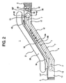
Fig. 2 is a schematic side elevational view of the escalator shown inFig. 1 ; -
Fig. 3 is an enlarged vertical cross sectional view along a line III-III inFig. 2 ; -
Fig. 4 is a schematic plan view showing an upper floor side of a main frame of the escalator shown inFig. 2 ; -
Fig. 5 is an enlarged view showing a right balustrade inFig. 3 ; -
Fig. 6 is an enlarged horizontal cross sectional view along a line VI-VI line inFig. 1 ; and -
Fig. 7 is a view showing another embodiment of a passenger conveyor, which is an example useful to understand the present invention but not an embodiment of it, in correspondence toFig. 5 . - A description will be given below of a passenger conveyor corresponding to an embodiment in accordance with the present invention on the basis of an escalator shown in
Figs. 1 to 6 . In general, anescalator 1 is structured on the basis of amain frame 4 placed between anupper floor 2 and alower floor 3 in an architectural structure. Themain frame 4 is constituted, as shown inFig. 3 , by a pair of left andright side frames 5A and 5B, abottom plate 6 andcross beams 7 which connect the left andright side frames side frames 5A and 5B are constituted by atop cord member 8A and a lower cord member 83 which extend in a longitudinal direction of the escalator, and avertical member 9 which connects thetop cord member 8A and thebottom cord member 8B. - An upper
horizontal portion 10 constituting an upper machine room is formed in a side of theupper floor 2 of themain frame 4 in the structure mentioned above, a lowerhorizontal portion 11 constituting a lower machine room is formed in a side of thelower floor 3, and aslope portion 12 is connected between the upperhorizontal portion 10 and the lowerhorizontal portion 11. In general, an upper portion of the upperhorizontal portion 10 and an upper portion of the lowerhorizontal portion 11 are closed byentrance floors - A pair of
main sprockets 13 and a pair of drivensprockets 14 are pivotally supported below theentrance floors horizontal portion 10 and the lowerhorizontal portion 11 of themain frame 4 structured in the manner mentioned above, respectively. A pair ofmain sprockets 13 are fixed to adrive shaft 15, and both end portions of thedrive shaft 15 are rotatably supported by abearing 16. Thebearing 16 is fixed tovertical members 9 of theside frames 5A and 5B, and a vertical projection of the bearing exists within a width h ofside frames 5A and 5B. - An
endless stair chain 17 is wound around themain sprocket 13 and the drivensprocket 14, and astair 18 is connected to thestair chain 17. Thestair 18 has afront wheel 19A and arear wheel 19B which travel on a guide rail placed within themain frame 4. Further, thefront wheel 19A is rotatably supported to a front wheel shaft protruding in a width direction of thestair 17, and a lot ofstairs 18 can be connected to thestair chain 17 by connecting the front wheel shaft to thestair chain 17. - Further, a
balustrade 20 is provided in a rising manner in each of theside frames 5A and 5B, and a movinghandrail 21 is guided to a peripheral edge of thebalustrade 20. Thebalustrade 20 is provided with asupport column 22 which is provided in a rising manner in thetop chord member 8A of theside frames 5A and 5B, ahandrail frame 23 which is supported to an upper end of thesupport column 22, abalustrade panel 24 which has an upper end supported to an upper end of thesupport column 22 within thehandrail frame 23 and a lower end supported to a lower end portion of thesupport column 22, and is positioned in a side of thestair 18 of thesupport column 22, aninner deck cover 26 which covers a lower portion of thebalustrade panel 24, askirt guard 27 which sections between theinner deck cover 26 and thestair 18, and anouter deck cover 25 which is provided in an outer side of thehandrail frame 23. - In this case, as shown in
Figs. 1 and3 , in the case that theescalator 1 is arranged close to a wall W of the architectural structure and stairs S are placed in an opposite side to the wall W, a decorativeoutward packing board 28 is provided in an outer side of thebalustrade 20 in a side of the stairs S vertically from theouter deck cover 25, thehandrail 23 of thebalustrade 20 in the side of the wall W is close to the wall W, a gap therebetween is closed by theouter deck cover 25, whereby an execution of theoutward packing board 28 is omitted. - The
balustrade panel 24 of thebalustrade 20 structured in the manner mentioned above has aperipheral edge portion 29 in which an end portion is faced into thehandrail frame 23, a base portion in which an end portion is faced into theinner deck cover 26, aninner surface portion 31 which is positioned in an opposite stair side with respect to theperipheral edge portion 29 and thebase portion 30 and has a height H corresponding to most of a vertical height, andslope portions angle 01 equal to or more than 90 degree with respect to theinner surface portion 31 between theinner surface portion 31 and theperipheral edge portion 29, and thebase portion 30. A recess portion open to thestair 18 is entirely formed by theinner surface portion 31, theperipheral edge portion 29 and thebase portion 30. The recess portion having theinner surface portion 31 with the height H is formed approximately all along the length of thebalustrade 20, guides a baggage of the passenger to the stair side as shown in arrows B and C inFig. 5 , and is formed such as to be connected to theperipheral edge portion 29 via theslope portion 32A in a terminal end portion in a longitudinal direction of thebalustrade 20. Further, the recess portion is expanded only at a width Wa in one side from a center A of the movinghandrail 21, and the width Wa contributes to expansion in an upper side of the passenger's foot. In this case, the recess portion is a linear recess portion which is formed by theperipheral edge portion 29, thebase portion 30 and theinner surface portion 31, however, may be formed as an entirely curved surface. - It is desirable that the
slope portion 32A between theperipheral edge portion 29 and theinner surface portion 31 in thebalustrade panel 24 has a slope angle which does not cross thehandrail frame 23 on a slope extension. Further, theslope portion 32B between thebase portion 30 and theinner surface portion 31 has a slope angle which does not cross theinner deck cover 26 on a slope extension. Further, a slope angle 02 (Fig. 6 ) of theslope portion 32A in the terminal end portion of thebalustrade 20 in the longitudinal direction is formed larger than theangle 01 mentioned above, whereby it is possible to smoothly guide the baggage of the passenger getting off the escalator positioned within the recess portion of thebalustrade panel 24 as shown by an arrow E. In this case, the structure in which the slope extension of theslope portion 32A does not cross thehandrail frame 23 is not essential, and there is no problem that the slope extension of theslope portion 32A may cross thehandrail frame 23 as far as a large step is not generated with respect to thehandrail frame 23. - In addition, an
operation switch 50 such as a start switch and a stop switch of theescalator 1 are provided in theslope portion 32A inFig. 6 which forms the terminal end slope surface of the terminal end portion in the longitudinal direction of thebalustrade panel 24, and aswitch box 51 is mounted to a back side thereof. As mentioned above, since an operating position is higher than the conventional case, by arranging theoperation switch 50 in the terminal end slope surface of the terminal end portion in the longitudinal direction of the balustrade panel, there is provided a function improving effect of an operability, that is, an easily remarkable function and an easily operable function. - In this case, the
inner surface portion 31 is a surface which is apart from the moving handrail of the balustrade described inclaim 1, and theslope portion 32A forms a surface which moves close to the moving handrail. Further, the recess portion provided in the balustrade in the portion surrounded by the moving handrail described inclaim 2 is a recess portion formed by theinner surface portion 31, theperipheral edge portion 29 and thebase portion 30. Further, the interval of the balustrade panel described inclaim 3 is an interval between the right andleft balustrade panels 24, the expanded balustrade panel interval is an interval W1 between the right and leftinner surface portions 31, and the interval of the moving handrail is an interval W2 between the right and left movinghandrails 21. - On the other hand, in the
drive shaft 15 fixing a pair ofmain sprockets 13, adrive sprocket 33 is fixed to an opposite stair side of onemain sprocket 13. Thedrive sprocket 33 is formed in a dish shape expanding toward thebearing 16, and a teeth portion formed in an outer periphery is formed such that the teeth portion of the drive sprocket 33 and theside frame 5A overlap seen from a flat face while facing into the width h of theside frame 5A in themain frame 4, in other words, the teeth portion of thedrive sprocket 33 and theside frame 5A are arranged such that vertical projections thereof lap over each other. Accordingly, three elements comprising the teeth portion of thedrive sprocket 33, thebearing 16 and theside frame 5A of themain frame 4 are positioned within the width h of theside frame 5A such that the vertical projections thereof overlap each other. - A
power transmission chain 34 is wound around the teeth portion of thedrive sprocket 33, and thepower transmission chain 34 is wound around asprocket 36 of adriving machine apparatus 35 placed within the upperhorizontal portion 10 of themain frame 4 corresponding to an outer side of a reciprocating passage of thestairs 18. Thedriving machine apparatus 35 is constituted by anelectric motor 37, areduction gear 38, abrake 39 and the like, however, thereduction gear 39 is not necessarily required. - A
handrail drive sprocket 40 is fixed to an opposite side to the stair in each of a pair ofmain sprockets 13, and ahandrail drive chain 41 is wound around thehandrail drive sprocket 40 as shown inFig. 4 . Thehandrail drive chain 41 is structured such as to drive a handrail drive apparatus 43 (Fig. 2 ) via a turningroller 42. Thehandrail drive apparatus 43 is structured such as to drive a return side of the movinghandrail 21 in an inner side of thebalustrade 20 by a well-known means. - Since the structure is made such as mentioned above, it is possible to omit the space which is required because the teeth portion of the
drive sprocket 33 has been actually positioned between the bearing 16 and thehandrail drive sprocket 40, and the similar space which is required between themain sprocket 13 in the side having nodrive sprocket 33 and thebearing 16 taking into consideration the installation balance of themain frame 4 and thebalustrade 20, so that it is possible to reduce the total width of themain frame 4, and it is possible to make an installation width Wo of theescalator 1 narrow. - Further, since the
drive mechanism apparatus 35 is placed in an outer side in the longitudinal direction from a moving locus in a turning portion of thestairs 18, a maintenance and inspection space is not blocked by the stairs in comparison with the structure in which the driving machine apparatus is attached to a periphery of thedrive shaft 15, and it is possible to easily maintain and inspect the drivingmachine apparatus 35. - In the case of placing the
narrow escalator 1 having the structure mentioned above in a narrow place of an architectural structure, for example, the existing stairs of a station house or the like, theescalator 1 is normally placed close to one wall W in a width direction of the stairs S, as shown inFig. 1 , and thebalustrade 20 in an opposite side of theescalator 1 to the wall W is formed as a partition wall between the stairs S and theescalator 1. In the case of placing theescalator 1 having the installation width Wo in the stairs S as mentioned above, the width of the stairs S utilized by the passenger becomes narrow, however, since the installation width Wo of theescalator 1 is narrow as mentioned above, it is possible to reduce the used width of the stairs S to the minimum. - Further, since the recess portion is actually formed by denting the
balustrade panel 24 arranged vertically at the positions of theperipheral edge portion 29 and thebase portion 30 to the outer direction of theescalator 1, an occasion that the baggage is in contact with thebalustrade panel 24 is reduced even if the passenger gets on the escalator while directing the baggage to thebalustrade panel 24, so that the passenger can gets on the escalator with slowing down. - In addition, in the terminal end portion in the longitudinal direction of the
balustrade panel 24, since theslope portion 32A is formed in thebalustrade panel 24 formed in the recess portion, and is inclined at the slope angle by which the slope extension of theslope portion 32A does not cross thehandrail frame 23, the passenger reaches the getting-off port in a state in which the passenger makes the baggage to face to the recess portion of thebalustrade panel 24. Accordingly, even if the passenger is going to get off the escalator in this state, the baggage is guided to the stairs side along theslope portion 32A, so that the baggage does not come into collision with the back side of thehandrail 23 corresponding to the member for guiding the movinghandrail 21, and it is possible to prevent the overturning trouble due to the baggage collision. -
Fig. 7 shows the other embodiment which is an example useful to understand the present invention and which is largely different from the embodiment mentioned above in the structure of the balustrade, and has the same structures as those of the embodiment mentioned above in the structure of the main frame, the stairs and the drive mechanism of the moving handrail. - In this case, a
balustrade 60 in this embodiment is constituted by abalustrade panel 61 which is vertically fixed to theside frame 5A via a fixingdevice 62, ahandrail frame 23 which is fixed to a peripheral edge of thebalustrade panel 61 via a fixingdevice 63 and guides the movinghandrail 21, a coveringbody 64 which is fixed to the fixingdevice 63 in the peripheral edge of thebalustrade panel 61 and covers a lower portion of the fixingdevice 63, aninner deck cover 65 which covers a base portion of thebalustrade panel 61 and an upper portion in a side of the fixingdevice 62, theskirt guard 27 which sections between theinner deck cover 65 and thestairs 18, and theouter deck cover 25 which is placed between thehandrail frame 23 and the peripheral edge of thebalustrade panel 61. - The
balustrade panel 61 is formed, for example, by a reinforced glass plate, a reinforced synthetic resin plate or the like, and has the same function serving as a design product as that of the outward packing product in the embodiment mentioned above. Further, the coveringbody 64 is placed at a slant with respect to thebalustrade panel 61, and the slope is set more gentle that the slope of the coveringbody 64 placed so as to oppose to the stairs moving section, such that a direction of the baggage of the passenger is not rapidly changed in the terminal end portion in the longitudinal direction of the balustrade. - In accordance with the
balustrade 60 having the structure mentioned above, since thesupport column 22, thebalustrade panel 24 and theoutward packing plate 28 in the embodiment mentioned above are structured by onebalustrade panel 61, it is possible to further expand an interval W3 between a pair of opposingbalustrade panels 61 in comparison with the interval W1 between thebalustrade panels 24 in accordance with the embodiment mentioned above. - In addition, it is possible to have a balustrade lighting equipment built-in by utilizing a
space 66 which is formed between an upper end (a peripheral edge) of thebalustrade panel 61 and thehandrail 23 by the coveringbody 64, whereby it is possible to provide thebalustrade 60 with light. Further, an operation switch may be provided in a terminal end portion in a balustrade longitudinal direction of the coveringbody 64, in the same manner as that of the embodiment. - In accordance with the embodiment having the structure mentioned above, it is possible to further expand the
balustrade panel 61, and it is possible to achieve the same operations and effects as those of the embodiment mentioned above. - In this case, the embodiment mentioned above is described on the basis of the escalator which is exemplified as the passenger conveyor. However, it goes without saying that the present invention can be applied to an electrically operated road in which no step is generated between the step plates. In this case, the structure of the embodiments mentioned above and claims can be applied by replacing the stairs described in the embodiments mentioned above and claims by the step plate.
- As mentioned above, in accordance with the present invention, it is possible to obtain the passenger conveyor which can sufficiently reduce the width, and it is possible to obtain the passenger conveyor which the passenger can get on even in the case that the width is reduced, and the baggage does not come into collision with the member for guiding the moving handrail at a time when the passenger gets off.
Claims (3)
- A passenger conveyor comprising
balustrades (20) provided on both sides of a stairs row connected in an endless manner and moving in a circulating manner, and
moving handrails (21) moving in synchronization with said stairs row and guided to peripheral edges of the balustrades,
wherein the inner surface (31) of the balustrade panel of each of said balustrades, facing the stairs row, is recessed with respect to a centerline (A) of the moving handrail and positioned on the opposite side of the centerline with respect to the stairs row,
characterized in that each of the balustrades comprises
a support column (22) provided in a rising manner in a of the convegor frame 5(4, top chord member 8(A)
a handrail frame (23) supported at an upper end of the support column;
a balustrade panel (24) with an upper end supported together with the upper end of the support column within the handrail frame and a lower end supported at a lower end of the support column, the balustrade panel being positioned at the side of the support column facing the stairs row; and
an inner deck cover (26) covering a lower portion the balustrade;
wherein the balustrade panel comprises
a peripheral edge portion (29) protruding into the handrail frame;
a base portion (30) protruding into the inner deck cover;
an inner surface (31) provided between said peripheral edge portion and said bare portion;
a first slope portion (32A) extending between the inner surface and the peripheral edge portion in a first angle of 90° or more with respect to the inner surface; and
a second slope portion (32B) extending between the inner surface and the base portion in a second angle of 90° or more with respect to the inner surface. - The passenger conveyor of claim 1, wherein the first angle is set such that the extension of the first slope portion (32A) in the slope direction does not cross the handrail frame (23) and wherein the second angle is set such that the extension of the second slope portion (32B) in the slope direction does not cross the inner deck cover (26).
- The passenger conveyor of claim 1, wherein in a terminal end portion of the balustrades in the moving direction of the stairs, the first angle is set to be larger than the second angle.
Applications Claiming Priority (1)
| Application Number | Priority Date | Filing Date | Title |
|---|---|---|---|
| PCT/JP2001/010730 WO2003048021A1 (en) | 2001-12-07 | 2001-12-07 | Passenger conveyor |
Publications (3)
| Publication Number | Publication Date |
|---|---|
| EP1454869A1 EP1454869A1 (en) | 2004-09-08 |
| EP1454869A4 EP1454869A4 (en) | 2006-11-15 |
| EP1454869B1 true EP1454869B1 (en) | 2013-02-20 |
Family
ID=11738009
Family Applications (1)
| Application Number | Title | Priority Date | Filing Date |
|---|---|---|---|
| EP01274915A Expired - Lifetime EP1454869B1 (en) | 2001-12-07 | 2001-12-07 | Passenger conveyor |
Country Status (5)
| Country | Link |
|---|---|
| EP (1) | EP1454869B1 (en) |
| JP (1) | JP4051343B2 (en) |
| CN (2) | CN1318289C (en) |
| AU (1) | AU2002222588A1 (en) |
| WO (1) | WO2003048021A1 (en) |
Families Citing this family (10)
| Publication number | Priority date | Publication date | Assignee | Title |
|---|---|---|---|---|
| JP4994118B2 (en) * | 2007-05-30 | 2012-08-08 | 株式会社日立製作所 | Passenger conveyor |
| JP5010984B2 (en) * | 2007-05-30 | 2012-08-29 | 株式会社日立製作所 | Passenger conveyor |
| JP2008308288A (en) * | 2007-06-14 | 2008-12-25 | Hitachi Ltd | Passenger conveyer |
| JP4827942B2 (en) * | 2009-03-13 | 2011-11-30 | 株式会社日立製作所 | Passenger conveyor |
| CN102020182B (en) * | 2010-12-16 | 2012-12-12 | 江南嘉捷电梯股份有限公司 | Handrail end device on escalator or moving sidewalk |
| JP2013184796A (en) * | 2012-03-08 | 2013-09-19 | Hitachi Ltd | Passenger conveyor |
| CN102756970A (en) * | 2012-07-17 | 2012-10-31 | 江南嘉捷电梯股份有限公司 | Device for preventing trolley from colliding with a handrail band |
| CN102963804A (en) * | 2012-11-26 | 2013-03-13 | 康力电梯股份有限公司 | Shock absorbing mechanism for step chain |
| CN106115444A (en) * | 2016-08-19 | 2016-11-16 | 广东广都电扶梯部件有限公司 | A kind of escalator guide rail connection structure |
| CN108246647B (en) * | 2018-04-02 | 2019-09-24 | 冯贵良 | A kind of agricultural product automatic sorting device and its control method |
Family Cites Families (18)
| Publication number | Priority date | Publication date | Assignee | Title |
|---|---|---|---|---|
| GB678454A (en) * | 1949-05-04 | 1952-09-03 | Waygood Otis Ltd | Moving stairway |
| JPS4329707Y1 (en) * | 1965-04-07 | 1968-12-05 | ||
| JPS4934309Y1 (en) * | 1970-06-11 | 1974-09-17 | ||
| JPS4935399B1 (en) * | 1970-12-11 | 1974-09-21 | ||
| JPS481389U (en) * | 1971-05-21 | 1973-01-09 | ||
| JPS5830237B2 (en) * | 1979-07-06 | 1983-06-28 | 株式会社日立製作所 | Man conveyor railing |
| JPS56117978A (en) * | 1980-02-20 | 1981-09-16 | Hitachi Ltd | Driving device for man conveyor |
| JPS61122278U (en) * | 1985-01-21 | 1986-08-01 | ||
| JPS61169490A (en) * | 1985-01-22 | 1986-07-31 | 三菱電機株式会社 | Handrail for passenger conveyor |
| JPS6331075U (en) * | 1986-08-13 | 1988-02-29 | ||
| JPS6487489A (en) * | 1987-09-29 | 1989-03-31 | Hitachi Ltd | Handrail for passenger conveyor |
| JP2507670B2 (en) * | 1990-05-30 | 1996-06-12 | 株式会社日立製作所 | Passenger conveyor |
| JPH07277650A (en) * | 1994-04-12 | 1995-10-24 | Hitachi Building Syst Eng & Service Co Ltd | Safety device on passenger conveyer |
| AU1882797A (en) * | 1996-02-29 | 1997-09-16 | Kone Oy | People mover and drive apparatus |
| JPH10194647A (en) * | 1997-01-17 | 1998-07-28 | Toshiba Elevator Prod Kk | Passenger conveyor |
| JP2000302364A (en) * | 1999-04-19 | 2000-10-31 | Toshiba Elevator Co Ltd | Drive device for passenger conveyor |
| JP2001139273A (en) * | 1999-11-16 | 2001-05-22 | Hitachi Ltd | Escalator for passenger |
| JP4266504B2 (en) * | 2000-08-31 | 2009-05-20 | 東芝エレベータプロダクツ株式会社 | Man conveyor |
-
2001
- 2001-12-07 WO PCT/JP2001/010730 patent/WO2003048021A1/en active Application Filing
- 2001-12-07 AU AU2002222588A patent/AU2002222588A1/en not_active Abandoned
- 2001-12-07 CN CNB018238521A patent/CN1318289C/en not_active Expired - Fee Related
- 2001-12-07 CN CNB200710091767XA patent/CN100560465C/en not_active Expired - Fee Related
- 2001-12-07 EP EP01274915A patent/EP1454869B1/en not_active Expired - Lifetime
- 2001-12-07 JP JP2003549221A patent/JP4051343B2/en not_active Expired - Fee Related
Also Published As
| Publication number | Publication date |
|---|---|
| JPWO2003048021A1 (en) | 2005-04-14 |
| AU2002222588A1 (en) | 2003-06-17 |
| EP1454869A1 (en) | 2004-09-08 |
| CN1561311A (en) | 2005-01-05 |
| EP1454869A4 (en) | 2006-11-15 |
| CN1318289C (en) | 2007-05-30 |
| CN100560465C (en) | 2009-11-18 |
| CN101041409A (en) | 2007-09-26 |
| JP4051343B2 (en) | 2008-02-20 |
| WO2003048021A1 (en) | 2003-06-12 |
Similar Documents
| Publication | Publication Date | Title |
|---|---|---|
| KR100485970B1 (en) | Passenger conveyor device | |
| EP1454869B1 (en) | Passenger conveyor | |
| JP2004514628A (en) | Escalator with step flange | |
| JPH0631151B2 (en) | Passenger conveyor | |
| JP2706141B2 (en) | Escalators or moving siderails | |
| CN210260811U (en) | Passenger conveyor | |
| EP1101724B1 (en) | Balustrades for an escalator | |
| JP4848327B2 (en) | Passenger conveyor | |
| JP4000774B2 (en) | Passenger conveyor | |
| JP2000211871A (en) | Handrail supporting device of man conveyor | |
| JP7086037B2 (en) | Passenger conveyor | |
| JP3811622B2 (en) | Inclined passenger conveyor | |
| JP3205330B2 (en) | Escalator device | |
| JP3884913B2 (en) | escalator | |
| JP5469049B2 (en) | Passenger conveyor and passenger conveyor steps | |
| JP5437985B2 (en) | Passenger conveyor and its steps | |
| JP4127752B2 (en) | Passenger conveyor | |
| KR100426459B1 (en) | Passenger conveyor | |
| JP2581854B2 (en) | Man conveyor equipment | |
| JP3884921B2 (en) | Passenger conveyor equipment | |
| JPH07291569A (en) | Safety device for passenger conveyer | |
| JPH07315743A (en) | Safety equipment for passenger conveyer | |
| JP5252402B2 (en) | Passenger conveyor | |
| JPH0416492A (en) | Platform plate for escalator | |
| JPS6351957B2 (en) |
Legal Events
| Date | Code | Title | Description |
|---|---|---|---|
| PUAI | Public reference made under article 153(3) epc to a published international application that has entered the european phase |
Free format text: ORIGINAL CODE: 0009012 |
|
| 17P | Request for examination filed |
Effective date: 20040630 |
|
| AK | Designated contracting states |
Kind code of ref document: A1 Designated state(s): AT BE CH CY DE DK ES FI FR GB GR IE IT LI LU MC NL PT SE TR |
|
| AX | Request for extension of the european patent |
Extension state: AL LT LV MK RO SI |
|
| RIC1 | Information provided on ipc code assigned before grant |
Ipc: B66B 23/02 20060101ALI20060719BHEP Ipc: B66B 23/22 20060101AFI20030618BHEP |
|
| A4 | Supplementary search report drawn up and despatched |
Effective date: 20061013 |
|
| 17Q | First examination report despatched |
Effective date: 20100210 |
|
| GRAP | Despatch of communication of intention to grant a patent |
Free format text: ORIGINAL CODE: EPIDOSNIGR1 |
|
| GRAS | Grant fee paid |
Free format text: ORIGINAL CODE: EPIDOSNIGR3 |
|
| GRAP | Despatch of communication of intention to grant a patent |
Free format text: ORIGINAL CODE: EPIDOSNIGR1 |
|
| GRAA | (expected) grant |
Free format text: ORIGINAL CODE: 0009210 |
|
| AK | Designated contracting states |
Kind code of ref document: B1 Designated state(s): DE FR |
|
| REG | Reference to a national code |
Ref country code: DE Ref legal event code: R096 Ref document number: 60147677 Country of ref document: DE Effective date: 20130418 |
|
| PLBE | No opposition filed within time limit |
Free format text: ORIGINAL CODE: 0009261 |
|
| STAA | Information on the status of an ep patent application or granted ep patent |
Free format text: STATUS: NO OPPOSITION FILED WITHIN TIME LIMIT |
|
| 26N | No opposition filed |
Effective date: 20131121 |
|
| REG | Reference to a national code |
Ref country code: DE Ref legal event code: R097 Ref document number: 60147677 Country of ref document: DE Effective date: 20131121 |
|
| PGFP | Annual fee paid to national office [announced via postgrant information from national office to epo] |
Ref country code: DE Payment date: 20141202 Year of fee payment: 14 |
|
| PGFP | Annual fee paid to national office [announced via postgrant information from national office to epo] |
Ref country code: FR Payment date: 20141208 Year of fee payment: 14 |
|
| REG | Reference to a national code |
Ref country code: DE Ref legal event code: R119 Ref document number: 60147677 Country of ref document: DE |
|
| REG | Reference to a national code |
Ref country code: FR Ref legal event code: ST Effective date: 20160831 |
|
| PG25 | Lapsed in a contracting state [announced via postgrant information from national office to epo] |
Ref country code: DE Free format text: LAPSE BECAUSE OF NON-PAYMENT OF DUE FEES Effective date: 20160701 |
|
| PG25 | Lapsed in a contracting state [announced via postgrant information from national office to epo] |
Ref country code: FR Free format text: LAPSE BECAUSE OF NON-PAYMENT OF DUE FEES Effective date: 20151231 |