EP1454830A1 - Medicine feeder - Google Patents
Medicine feeder Download PDFInfo
- Publication number
- EP1454830A1 EP1454830A1 EP02781749A EP02781749A EP1454830A1 EP 1454830 A1 EP1454830 A1 EP 1454830A1 EP 02781749 A EP02781749 A EP 02781749A EP 02781749 A EP02781749 A EP 02781749A EP 1454830 A1 EP1454830 A1 EP 1454830A1
- Authority
- EP
- European Patent Office
- Prior art keywords
- rotor
- medicine
- motor
- driven gear
- tablet
- Prior art date
- Legal status (The legal status is an assumption and is not a legal conclusion. Google has not performed a legal analysis and makes no representation as to the accuracy of the status listed.)
- Granted
Links
Images



Classifications
-
- A—HUMAN NECESSITIES
- A61—MEDICAL OR VETERINARY SCIENCE; HYGIENE
- A61J—CONTAINERS SPECIALLY ADAPTED FOR MEDICAL OR PHARMACEUTICAL PURPOSES; DEVICES OR METHODS SPECIALLY ADAPTED FOR BRINGING PHARMACEUTICAL PRODUCTS INTO PARTICULAR PHYSICAL OR ADMINISTERING FORMS; DEVICES FOR ADMINISTERING FOOD OR MEDICINES ORALLY; BABY COMFORTERS; DEVICES FOR RECEIVING SPITTLE
- A61J3/00—Devices or methods specially adapted for bringing pharmaceutical products into particular physical or administering forms
-
- B—PERFORMING OPERATIONS; TRANSPORTING
- B65—CONVEYING; PACKING; STORING; HANDLING THIN OR FILAMENTARY MATERIAL
- B65B—MACHINES, APPARATUS OR DEVICES FOR, OR METHODS OF, PACKAGING ARTICLES OR MATERIALS; UNPACKING
- B65B5/00—Packaging individual articles in containers or receptacles, e.g. bags, sacks, boxes, cartons, cans, jars
- B65B5/10—Filling containers or receptacles progressively or in stages by introducing successive articles, or layers of articles
- B65B5/101—Filling containers or receptacles progressively or in stages by introducing successive articles, or layers of articles by gravity
- B65B5/103—Filling containers or receptacles progressively or in stages by introducing successive articles, or layers of articles by gravity for packaging pills or tablets
-
- B—PERFORMING OPERATIONS; TRANSPORTING
- B65—CONVEYING; PACKING; STORING; HANDLING THIN OR FILAMENTARY MATERIAL
- B65B—MACHINES, APPARATUS OR DEVICES FOR, OR METHODS OF, PACKAGING ARTICLES OR MATERIALS; UNPACKING
- B65B35/00—Supplying, feeding, arranging or orientating articles to be packaged
- B65B35/06—Separating single articles from loose masses of articles
- B65B35/08—Separating single articles from loose masses of articles using pocketed conveyors
-
- B—PERFORMING OPERATIONS; TRANSPORTING
- B65—CONVEYING; PACKING; STORING; HANDLING THIN OR FILAMENTARY MATERIAL
- B65B—MACHINES, APPARATUS OR DEVICES FOR, OR METHODS OF, PACKAGING ARTICLES OR MATERIALS; UNPACKING
- B65B9/00—Enclosing successive articles, or quantities of material, e.g. liquids or semiliquids, in flat, folded, or tubular webs of flexible sheet material; Subdividing filled flexible tubes to form packages
- B65B9/06—Enclosing successive articles, or quantities of material, in a longitudinally-folded web, or in a web folded into a tube about the articles or quantities of material placed upon it
-
- G—PHYSICS
- G07—CHECKING-DEVICES
- G07F—COIN-FREED OR LIKE APPARATUS
- G07F17/00—Coin-freed apparatus for hiring articles; Coin-freed facilities or services
- G07F17/0092—Coin-freed apparatus for hiring articles; Coin-freed facilities or services for assembling and dispensing of pharmaceutical articles
Definitions
- the present invention relates to a medicine feeder.
- a medicine feeder comprising a case supporting base provided with a motor and a medicine containing case removably mounted on the case supporting base.
- the motor when the motor is driven to rotate a rotor provided in the medicine containing case via a plurality of gears, the medicine held in pocket portions formed on the rotor can be discharged from a discharge portion of the case supporting base.
- a problem of the present invention is to provide a medicine feeder that is simple in construction and yet capable accurately preventing drawbacks from occurring due to jamming of the medicine or the like.
- the present invention provides a medicine feeder in which a motor provided in a case supporting base is driven to rotate a rotor in a medicine containing case supported in the case supporting base via a plurality of gears; medicine contained in the medicine containing case are held in each pocket portion of the rotor and are moved to a discharge portion of the case supporting base to discharge the medicine from the discharge portion, wherein:
- the power cut-off portion does not allow a drive power from the motor to be transmitted to the rotor, whereby any disadvantages such as damage of medicine, burnout of motor and so on would not occur.
- the power cut-off portion comprises a friction generating member provided between the rotor and the driven gear.
- the friction generating member may comprise a ring member having an annular shape, the ring member being made of synthetic resin material.
- the power cut-off portion may comprise indentations provided on either one of the rotor and the driven gear and protrusions provided on the other, the protrusions engaging with the indentations, whereby the engagement of the indentation and the protrusions is released when a braking force of more than a predetermined value acts on the rotor.
- the power cut-off portion is provided in the power transmission passage reaching the rotor from the motor, it is possible to reliably preventing any disadvantages such as damage of the medicine, burnout of the motor and so on even if medicine jam or so disables the motor from rotating.
- Fig. 1 shows a tablet feed apparatus 2 having a plurality of tablet feeders 1 according to the present invention.
- inner and outer double drums 22, 23 are contained inside a cabinet 21 with the upper and lower end rotatably supported.
- On the outer surface of each drum 22, 23 are provided the plurality of tablet feeders 1, while on the inner surface are formed a plurality of drop guide passages 24 in which the tablets discharged from each tablet feeder 1 provided in a vertical direction drop.
- Beneath the drums 22, 23 are provided lower plates 25, 26 having shutter not shown for temporarily receiving the tablets dropping from each drop guide passage 24.
- Under the lower plates 25, 26 are provided small hoppers 27 correspondingly to each drop guide passage 24.
- Each small hopper 27 receives the tablets dropping from the drop guide passages 24 of the inner drum 22 and the drop guide passages 24 of the outer drum 23.
- Under the small hoppers 27 is provided a collection hopper 28 for collecting the tablets dropping from the small hoppers 27.
- Beneath the collection hopper 28 is provided a packing hopper 29.
- Under the packing hopper 29 is provided a tablet packing section 30.
- the tablet packing section 30 comprises a roll 33 comprising a wound packing sheet 31 and removably mounted on a roll shaft 32, a printer 34 for printing information such as patient name, tablet name, dosing time, dose and the like on the packing sheet 31 reeled out from the roll 33, a triangle plate not shown in detail for folding the packing sheet 31 into two so that the tablets discharged from the packing hopper 29 can be introduced, a pair of heater rollers 35 for sealing the packing sheet 31 with the tablets introduced, and a conveyor 37 for conveying the medicine package belt 36, which has passed through the heater rollers 35 and has been discharged in an obliquely lower direction, in an obliquely upper direction to direct it to a discharge port not shown.
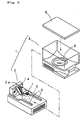
- the tablet feeder 1 as shown in Fig. 2, is constituted by a case supporting base 3 provided on the tablet feed apparatus 2 and a tablet containing case 4 removably mounted on the case supporting base 3.
- the case supporting base 3 is provided with guide portions 5 on the upper surface side by side with a predetermined distance. Inside the case supporting base 3 is housed a motor 6 which is driven and controlled based on a control signal from a control unit not shown. The rotation shaft of the motor 6 protrudes from the upper surface of the case supporting base 3. On the protruding portion is integrated a driving gear 7.
- the case supporting base 3 is formed with a discharge passage 3a in which a sensor 14 for detecting the tablets passing through it.
- the tablet containing case 4 has a substantially box-like shape, the upper surface of which can be opened and closed by a lid 8.
- the upper surface of the bottom wall of the tablet containing case 4 is formed in a substantially conical shape, in which a rotor 9 is provided.
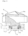
- the upper surface of the rotor 9, as shown in Fig. 4 has a substantially conical shape and is formed with step portions 9a which gradually protrude at equally spaced three portions in a circumferential direction.
- pocket portions 10 each having a groove shape extending in a vertical direction are formed at a plurality of positions spacing with an equal angle.
- the pocket portion 10 has a width and depth possible to hold only one tablet contained in the case 4.
- the discharge port 11 On the bottom wall of the tablet containing case 4 is formed with a discharge port 11.
- the discharge port 11 has a width dimension that includes only one of the pocket portions 10 of the rotor 9.
- On the central portion of the bottom surface of the rotor 9 is provided a rotation shaft 12.
- the rotation shaft 12 protrudes from the lower surface of the bottom wall of the tablet containing case 4.
- On the outer periphery of the end surface of the rotation shaft 12 is formed an annular protruding portion 12a.
- a driven gear 13 is attached by an attachment member 15.
- the attachment member 15 comprises a shaft portion 15a and a flange portion 15b and is fixed on the rotation shaft 12 of the rotor 9 with a screw 16 inserted into the central portion of the attachment member 15.
- the shaft portion 15a is inserted into a central aperture 13a of the driven gear 13 to rotatably support the driven gear 13.
- the flange portion 15b supports the driven gear 13 between the flange portion 15b and the end surface of the rotation shaft of the rotor 9 via a ring member 17.
- the ring member 17 comprises, for example, an O-ring made of synthetic resin and generates a predetermined friction force in accordance with a gap between the rotor 9 and the attachment member 15, i.e., a press contact force with the ring member 17.
- a friction force is set so that when tablet jam prevents the rotor 9 from rotating, a slip can be caused between the ring member 17 and the rotor 9 or the attachment member 15 before the tablet suffers damages such as break or split.
- the driven gear 13 is made of synthetic resin material. On the upper surface of the driven gear 13 is formed an annular groove 13b with which the annular protruding portion 12a formed on the rotation shaft 12 of the rotor 9 rotatably engages.
- annular recess portion 13c On the lower opening edge portion is formed an annular recess portion 13c in which the ring member 17 is positioned.
- Annular grooves formed on the outer periphery of the upper and lower surfaces of the driven gear 13 is provided as so called a relief in order to make the thickness equal.
- the tablet feeder 1 containing the tablets concerned is driven. That is to say, when the motor 6 is driven, a drive power is transmitted to the driven gear 13 via the driving gear 7. To the attachment member 15 from the driven gear 13, the drive power is transmitted by a friction force against the ring member 17 positioned between the both members.
- rotation of the driving gear 7 allows the attachment member 15, the driven gear 13 and the rotor 9 to rotate via the ring member 17 so that the tablets held in the pocket portions 10 can be discharged from the discharge passage 3a one after another.
- the discharged number of the tablets is counted by the sensor 14 provided in the discharge passage 3a. When the discharged number comes up to a predetermined number, the motor 6 is stopped.
- each tablet feeder 1 fall on the lower plates 25, 26 through the drop guide passages 24.
- a shutter not shown is opened at a predetermined timing, the tablets are introduced into the tablet packing section 30 through the small hoppers 27, the collection hopper 28 and the packing hopper 29 and packed by one dose in the tablet packing section 30.
- the O-ring is used as the ring member 17 but the shape, material and so on of the ring member 17 is not limited to this.
- a ling-like rubber sheet 18 etc. on at least one of the contact surfaces between the driven gear 13 and the rotation shaft of the rotor 9 to change a friction coefficient.
- the ring member 17 etc. is interposed between the rotor 9 (and the attachment member 1) and the driven gear 13 to cause a slip, though the same construction may be used between the rotation shaft of the motor 6 and the driving gear 7. Also, in stead of the driving gear 7 and the driven gear 13, as shown in Fig. 6, rollers 7', 13' with rubbers 19, 20 attached on the outer surface thereof may be used so that the rubbers can come into contact with each other to cause a slip therebetween.
- the attachment member 15 is attached by means of the screw 16, though it is preferable in that the friction force against the ring member 17 can be adjustable to form a mail screw on the end outer surface of the shaft portion 15a of the attachment member 15 and directly screw it into the rotor 9.
- a friction forming member such as the ring member 17, the rubber sheet 18, the rubbers 19, 20 and so on is used, though indentations may be provided on either one of the rotor 9 (or attachment member 15) and the driven gear 13 while protrusions that engage with the indentation may be provided on the other so that when a braking force of more than a predetermined value acts on the rotor 9, engagements of the indentations and the protrusions are released and the drive power is cut-off.
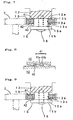
- indentations 41 are formed on the annular protruding portion 12a of the rotation shaft 12 of the rotor 9 while protrusions 42 which engage with the indentations 41 may be formed on the annular groove 13b of the driven gear 13.
- a spring 43 may be provided between the annular recess portion 13c of the driven gear 13 and the flange portion 15b of the attachment member 15 to urge the driven gear 13 upward so that the engagement of the indentations 41 and the protrusions 42 can be maintained.
- the indentations 41 as shown in Fig. 8, comprise a plurality of slopes 41a and step portions 41b which are continuously formed in a circumferential direction.
- the engagement of the indentations 41 and the protrusions 42 allows the drive power of the motor 6 to be transmitted to the rotor 9 from the driven gear 13.
- the protrusions 42 slide on the slops of the indentations 41 and overpass the step portions 41b as the driven gear 13 moves downward, whereby the drive power of the motor 6 can be cut-off.
- indentations 41 may be formed on the annular recess portion 13c of the driven gear 13 while protrusions 42 which engage with the indentations 41 may be formed on the flange portion 15b of the attachment member 15.
- the spring as shown in Fig. 7 is not necessary.
Landscapes
- Engineering & Computer Science (AREA)
- Mechanical Engineering (AREA)
- Physics & Mathematics (AREA)
- General Physics & Mathematics (AREA)
- Health & Medical Sciences (AREA)
- Life Sciences & Earth Sciences (AREA)
- Veterinary Medicine (AREA)
- Pharmacology & Pharmacy (AREA)
- Chemical & Material Sciences (AREA)
- Animal Behavior & Ethology (AREA)
- General Health & Medical Sciences (AREA)
- Public Health (AREA)
- Medicinal Chemistry (AREA)
- Basic Packing Technique (AREA)
- Medical Preparation Storing Or Oral Administration Devices (AREA)
- Supply Of Fluid Materials To The Packaging Location (AREA)
- Acyclic And Carbocyclic Compounds In Medicinal Compositions (AREA)
- Pharmaceuticals Containing Other Organic And Inorganic Compounds (AREA)
- Steroid Compounds (AREA)
Abstract
Description
Claims (5)
- A medicine feeder in which a motor provided in a case supporting base is driven to rotate a rotor in a medicine containing case supported in the case supporting base via a plurality of gears; medicine contained in the medicine containing case are held in each pocket portion of the rotor and are moved to a discharge portion of the case supporting base to discharge the medicine from the discharge portion, characterized in that:said plurality of gears are composed of a driving gear connected to a rotation shaft of the motor and a driven gear engaging with the driving gear; anda power cut-off portion is provided in a power transmission passage reaching the rotor from the motor through the both gears so that a power from the motor is cut off when a braking force of more than a predetermined value acts on the rotor.
- The medicine feeder as in Claim 1, characterized in that the power cut-off portion comprises a friction generating member provided between the rotor and the driven gear.
- The medicine feeder as in Claim 2, characterized in that a friction force generated by the friction generating member is adjustable.
- The medicine feeder as in Claim 2 or 3, characterized in that the friction generating member comprises a ring member having an annular shape, the ring member being made of synthetic resin material, a shaft portion fixed on the rotor, the shaft portion rotatably supporting the driven gear, and a flange portion for supporting the ring member between the flange portion and the driven gear.
- The medicine feeder as in Claim 1, characterized in that the power cut-off portion comprises indentations provided on either one of the rotor and the driven gear and protrusions provided on the other, the protrusions engaging with the indentations, whereby the engagement of the indentation and the protrusions is released when a braking force of more than a predetermined value acts on the rotor.
Applications Claiming Priority (3)
| Application Number | Priority Date | Filing Date | Title |
|---|---|---|---|
| JP2001348895 | 2001-11-14 | ||
| JP2001348895 | 2001-11-14 | ||
| PCT/JP2002/011824 WO2003042042A1 (en) | 2001-11-14 | 2002-11-13 | Medicine feeder |
Publications (3)
| Publication Number | Publication Date |
|---|---|
| EP1454830A1 true EP1454830A1 (en) | 2004-09-08 |
| EP1454830A4 EP1454830A4 (en) | 2008-03-05 |
| EP1454830B1 EP1454830B1 (en) | 2011-06-08 |
Family
ID=19161643
Family Applications (1)
| Application Number | Title | Priority Date | Filing Date |
|---|---|---|---|
| EP02781749A Expired - Lifetime EP1454830B1 (en) | 2001-11-14 | 2002-11-13 | Medicine feeder |
Country Status (10)
| Country | Link |
|---|---|
| US (1) | US7040505B2 (en) |
| EP (1) | EP1454830B1 (en) |
| JP (1) | JP4621428B2 (en) |
| KR (2) | KR20030040039A (en) |
| CN (1) | CN1318266C (en) |
| AT (1) | ATE512059T1 (en) |
| CA (1) | CA2467071A1 (en) |
| NO (1) | NO20042437L (en) |
| TW (1) | TWI247713B (en) |
| WO (1) | WO2003042042A1 (en) |
Cited By (1)
| Publication number | Priority date | Publication date | Assignee | Title |
|---|---|---|---|---|
| EP2754431A4 (en) * | 2011-09-05 | 2015-05-20 | Takazono Technology Inc | Drug retrieval device |
Families Citing this family (47)
| Publication number | Priority date | Publication date | Assignee | Title |
|---|---|---|---|---|
| US6213110B1 (en) | 1999-12-16 | 2001-04-10 | Odyssey Paintball Products, Inc. | Rapid feed paintball loader |
| USRE45986E1 (en) | 1999-12-16 | 2016-04-26 | Gi Sportz Direct Llc | Spring loaded feed mechanism for paintball loader |
| EP1495279A4 (en) | 2002-04-12 | 2010-07-21 | Nat Paintball Supply Inc | Differential detection system for controlling feed of a paintball loader |
| US7343909B2 (en) | 2004-04-28 | 2008-03-18 | Kee Action Sports I Llc | Mechanical drive assist for active feed paintball loader |
| US7428899B2 (en) | 2004-10-14 | 2008-09-30 | Kee Action Sports I Llc | Device for storing projectile balls and feeding them into the projectile chamber of a gun |
| US20070017495A1 (en) | 2004-10-14 | 2007-01-25 | Heddies Andresen | Procedure and device for feeding balls into the projectile chamber of a handgun |
| US7234456B2 (en) * | 2004-10-14 | 2007-06-26 | Kee Action Sports | Device for feeding balls into the ball chamber of a handgun |
| US7694669B2 (en) * | 2004-12-08 | 2010-04-13 | Kee Action Sports I, Llc | Paintball loader feed mechanism |
| WO2007033309A2 (en) * | 2005-09-13 | 2007-03-22 | National Paintball Supply, Inc. | Clutch and detection means for paintball marker loader |
| CN101317070A (en) * | 2005-10-11 | 2008-12-03 | 即动运动有限公司 | Magnetic Drive Bypass System for Paintball Loaders |
| US8251050B2 (en) | 2005-10-11 | 2012-08-28 | Kee Action Sports I Llc | Magnetic drive bypass system for paintball loader |
| US8402959B1 (en) | 2008-03-19 | 2013-03-26 | Kee Action Sports I Llc | Magnetic force feed projectile feeder drive mechanism |
| USD604371S1 (en) | 2008-08-29 | 2009-11-17 | Kee Action Sports I Llc | Anti-jam mechanism for a paintball loader |
| US8430269B2 (en) * | 2008-09-30 | 2013-04-30 | Jvm Co., Ltd. | Tablet cassette of automatic tablet packing apparatus |
| TWI485093B (en) * | 2008-11-21 | 2015-05-21 | Yuyama Mfg Co Ltd | Lozenge delivery device |
| JP2010168110A (en) * | 2008-12-26 | 2010-08-05 | Takazono Sangyo Co Ltd | Medicine storage container |
| US8135497B2 (en) | 2010-01-13 | 2012-03-13 | Joslyn Matthew I | Portable, personal medication dispensing apparatus and method |
| IT1399486B1 (en) * | 2010-03-31 | 2013-04-19 | Ima Safe S R L | IMPROVED WITH DISTRIBUTOR UNITS AND PERFECTED DISTRIBUTOR UNIT |
| CN102905979B (en) * | 2010-05-17 | 2015-05-20 | 株式会社汤山制作所 | pill box |
| CN101863319B (en) * | 2010-06-22 | 2011-11-09 | 武汉人天包装技术有限公司 | Automatically-rotating explosive machine |
| KR101871840B1 (en) | 2011-01-14 | 2018-06-27 | 가부시키가이샤 유야마 세이사쿠쇼 | Tablet cassette |
| KR101254658B1 (en) * | 2011-03-15 | 2013-04-15 | (주)제이브이엠 | Chemical supply device |
| KR101293099B1 (en) * | 2011-03-15 | 2013-08-12 | (주)제이브이엠 | Drug dispenser |
| KR101254659B1 (en) * | 2011-03-15 | 2013-04-15 | (주)제이브이엠 | Drug dispenser |
| KR101254651B1 (en) * | 2011-03-15 | 2013-04-15 | (주)제이브이엠 | Drug dispenser |
| US9150119B2 (en) | 2013-03-15 | 2015-10-06 | Aesynt Incorporated | Apparatuses, systems, and methods for anticipating and delivering medications from a central pharmacy to a patient using a track based transport system |
| US9511945B2 (en) | 2012-10-12 | 2016-12-06 | Aesynt Incorporated | Apparatuses, systems, and methods for transporting medications from a central pharmacy to a patient in a healthcare facility |
| NL2009865C2 (en) * | 2012-11-22 | 2014-05-27 | Vmi Holland Bv | Device for dispensing and packing solid substances. |
| KR101559163B1 (en) * | 2013-01-23 | 2015-10-12 | 주식회사 인포피아 | Cartridge for drug dispensing apparatus having auto locking function |
| KR101511263B1 (en) * | 2013-01-23 | 2015-04-13 | 주식회사 인포피아 | Cartridge for drug dispensing apparatus having rolling rotatable drum |
| EP3011254B1 (en) | 2013-06-21 | 2019-01-30 | Kee Action Sports I LLC | Compressed gas gun having built-in, internal projectile feed mechanism |
| CN103407603B (en) * | 2013-08-23 | 2015-12-23 | 海南康芝药业股份有限公司 | A kind of preparation method of children's medicine divided dose and process units and product |
| EP3047837A4 (en) * | 2013-09-20 | 2017-05-10 | Takazono Technology Incorporated | Drug supply unit |
| CN103935639A (en) * | 2014-05-09 | 2014-07-23 | 深圳国控医疗有限公司 | Medicine box |
| JP6569909B2 (en) * | 2016-01-21 | 2019-09-04 | 株式会社トーショー | Tablet cassette |
| JP2016172007A (en) * | 2016-04-22 | 2016-09-29 | 株式会社タカゾノテクノロジー | Drug extracting device |
| JP6759916B2 (en) * | 2016-09-16 | 2020-09-23 | 株式会社湯山製作所 | Tablet cassette |
| CN106956792A (en) * | 2017-05-06 | 2017-07-18 | 福州大学 | Chinese chestnut Seed arrangement ordering machine and its method of work based on three shaft ball screw slide units |
| CN107440910B (en) * | 2017-08-11 | 2023-07-18 | 昆明理工大学 | A drug delivery device capable of sorting drug particles and its application method |
| USD961002S1 (en) | 2019-12-30 | 2022-08-16 | Kore Outdoor (Us), Inc. | Projectile loader |
| US12376714B2 (en) * | 2020-08-10 | 2025-08-05 | Shruti Balwalli-Udyawer | Portable casing for sanitary products |
| JP7424629B2 (en) * | 2020-09-15 | 2024-01-30 | 株式会社トーショー | pill cassette |
| WO2022072443A1 (en) | 2020-09-30 | 2022-04-07 | Kore Outdoor (Us), Inc. | Compressed gas projectile launching devices |
| USD992671S1 (en) | 2020-10-08 | 2023-07-18 | Canadian Imperial Bank Of Commerce, As Agent | Projectile launcher and loader |
| CN112581692B (en) * | 2020-12-30 | 2022-04-19 | 天津森茂科技有限公司 | AIDS-preventing article vending machine for different sexes |
| US11498761B1 (en) * | 2021-06-22 | 2022-11-15 | Vmi Holland B.V. | Method for dispensing discrete medicaments, a test station for testing a feeder unit, and a method for determining a fill level of a feeder unit |
| CN113679612B (en) * | 2021-08-27 | 2023-06-23 | 河南省中医院(河南中医药大学第二附属医院) | A medicine dispensing device for nursing |
Family Cites Families (31)
| Publication number | Priority date | Publication date | Assignee | Title |
|---|---|---|---|---|
| US2577394A (en) * | 1946-06-11 | 1951-12-04 | Zunino Carl | Dispensing machine |
| US2742184A (en) * | 1950-12-26 | 1956-04-17 | Fairchild S Inc | Dispensing device for a counting and packing machine |
| JPS424745Y1 (en) * | 1964-03-03 | 1967-03-13 | ||
| US3785525A (en) * | 1972-01-31 | 1974-01-15 | Safe Well Mfg Co | Chemical tablet dispensing device for wells |
| JPS5827392Y2 (en) * | 1977-04-13 | 1983-06-14 | 三菱電機株式会社 | Friction torque generator |
| US4662538A (en) * | 1984-09-28 | 1987-05-05 | Autotrol Corporation | Bactericidal pellet dispenser |
| JPS61179422A (en) | 1985-02-05 | 1986-08-12 | Nissan Motor Co Ltd | Glass having variable light transmittance |
| JPS61179422U (en) * | 1985-04-27 | 1986-11-08 | ||
| JPS6319420A (en) * | 1986-07-08 | 1988-01-27 | Daiko Denshi Kenkyusho:Kk | Torque overload preventive device |
| US5014877A (en) * | 1989-10-30 | 1991-05-14 | Autotrol Corporation | Pellet dispenser |
| WO1991018808A1 (en) * | 1990-06-04 | 1991-12-12 | Toren Consulting Pty. Limited | Dispensing container for tablets |
| JPH04107523U (en) * | 1991-03-01 | 1992-09-17 | 株式会社ヨシダ電機 | Overload prevention clutch |
| US5141129A (en) * | 1991-03-19 | 1992-08-25 | Jennings Paul D | Article dispenser with selective child-resistance configuration |
| JPH059731A (en) * | 1991-07-03 | 1993-01-19 | Vacuum Metallurgical Co Ltd | Storage and transportation method for electronic parts |
| JPH0579731A (en) | 1991-09-24 | 1993-03-30 | Mitsubishi Electric Corp | Air conditioner |
| JPH0579731U (en) * | 1992-03-24 | 1993-10-29 | 京セラ株式会社 | Slip device for small equipment |
| JPH07279989A (en) * | 1994-04-13 | 1995-10-27 | Ricoh Co Ltd | Spring clutch |
| JP2933837B2 (en) | 1994-10-21 | 1999-08-16 | 株式会社湯山製作所 | Drug packaging device |
| JP3213512B2 (en) * | 1995-06-09 | 2001-10-02 | 株式会社豊田自動織機 | Overload protection device |
| US5667096A (en) * | 1995-07-18 | 1997-09-16 | Wu; King-Sheng | Drug storing apparatus for automatic drug dispensing machines |
| JP3519835B2 (en) * | 1995-09-05 | 2004-04-19 | 三洋電機株式会社 | Solid preparation filling device |
| JP3222374B2 (en) * | 1996-01-26 | 2001-10-29 | 株式会社湯山製作所 | Drug storage and removal device |
| JP3276847B2 (en) * | 1996-05-31 | 2002-04-22 | 株式会社湯山製作所 | Pill feeder |
| JP4318766B2 (en) * | 1997-06-17 | 2009-08-26 | 株式会社湯山製作所 | Tablet filling equipment |
| JP3840602B2 (en) * | 1998-06-25 | 2006-11-01 | 井関鉄工株式会社 | Torque limiter |
| JP2000095201A (en) * | 1998-09-25 | 2000-04-04 | Sanyo Electric Co Ltd | Tablet feeder |
| WO2000018644A1 (en) * | 1998-09-29 | 2000-04-06 | Sanyo Electric Co., Ltd. | Drug feeder |
| JP4298834B2 (en) * | 1999-01-14 | 2009-07-22 | 株式会社湯山製作所 | Tablet feeder |
| JP2001082502A (en) * | 1999-09-10 | 2001-03-27 | Nok Vibracoustic Kk | Coupling |
| JP2002048212A (en) * | 2000-08-04 | 2002-02-15 | Mitsubishi Heavy Ind Ltd | Mechanism for preventing excess torque |
| US6585132B2 (en) * | 2001-09-24 | 2003-07-01 | Jun H. Kim | Tablet cassette assembly with slider cabinets for automatic tablet dispensing and packaging system |
-
2002
- 2002-10-21 KR KR1020020064104A patent/KR20030040039A/en not_active Withdrawn
- 2002-11-13 AT AT02781749T patent/ATE512059T1/en not_active IP Right Cessation
- 2002-11-13 JP JP2003543893A patent/JP4621428B2/en not_active Expired - Fee Related
- 2002-11-13 TW TW091133297A patent/TWI247713B/en active
- 2002-11-13 CA CA002467071A patent/CA2467071A1/en not_active Abandoned
- 2002-11-13 EP EP02781749A patent/EP1454830B1/en not_active Expired - Lifetime
- 2002-11-13 CN CNB02822485XA patent/CN1318266C/en not_active Expired - Fee Related
- 2002-11-13 KR KR1020047007163A patent/KR100945541B1/en not_active Expired - Fee Related
- 2002-11-13 WO PCT/JP2002/011824 patent/WO2003042042A1/en not_active Ceased
- 2002-11-13 US US10/495,226 patent/US7040505B2/en not_active Expired - Fee Related
-
2004
- 2004-06-11 NO NO20042437A patent/NO20042437L/en unknown
Cited By (1)
| Publication number | Priority date | Publication date | Assignee | Title |
|---|---|---|---|---|
| EP2754431A4 (en) * | 2011-09-05 | 2015-05-20 | Takazono Technology Inc | Drug retrieval device |
Also Published As
| Publication number | Publication date |
|---|---|
| JPWO2003042042A1 (en) | 2005-03-03 |
| KR20030040039A (en) | 2003-05-22 |
| TWI247713B (en) | 2006-01-21 |
| CA2467071A1 (en) | 2003-05-22 |
| NO20042437L (en) | 2004-08-13 |
| CN1318266C (en) | 2007-05-30 |
| EP1454830A4 (en) | 2008-03-05 |
| KR20050044411A (en) | 2005-05-12 |
| WO2003042042A1 (en) | 2003-05-22 |
| US20040245276A1 (en) | 2004-12-09 |
| ATE512059T1 (en) | 2011-06-15 |
| EP1454830B1 (en) | 2011-06-08 |
| US7040505B2 (en) | 2006-05-09 |
| KR100945541B1 (en) | 2010-03-09 |
| JP4621428B2 (en) | 2011-01-26 |
| TW200300119A (en) | 2003-05-16 |
| CN1585711A (en) | 2005-02-23 |
Similar Documents
| Publication | Publication Date | Title |
|---|---|---|
| EP1454830B1 (en) | Medicine feeder | |
| EP1285850A2 (en) | Tablet feeder | |
| US8020356B2 (en) | Medicine packaging apparatus and method of packaging medicine | |
| US20140231446A1 (en) | Medicine dispenser, method of discharging medicine, and automatic medicine packing machine including the dispenser | |
| JP4954266B2 (en) | Automatic medicine packaging machine | |
| EP0760234A1 (en) | Medication packaging apparatus | |
| JPH09323701A (en) | Tablet feeder | |
| CN102512325A (en) | Tablet feeder | |
| WO2010101098A1 (en) | Powder removing device for tablet feeder | |
| TW201041782A (en) | Medicine packaging device | |
| KR20100059679A (en) | Medicine discharge device and automatic medicine packing machine including the device | |
| JP2023086768A (en) | Tablet dividing method, tablet dividing device, and tablet packaging device | |
| JP6777832B1 (en) | Powder supply device and powder packaging device | |
| US6766920B2 (en) | Medicine feed unit | |
| JP6630518B2 (en) | Unwrapping system | |
| CN116946445B (en) | Workpiece supply device | |
| KR101616107B1 (en) | Cartridge for drug | |
| KR102061433B1 (en) | A blister packaging device capable of preventing breakage of tablets | |
| JP7555590B2 (en) | Powdered medicine distribution device and powdered medicine packaging device | |
| JP6643836B2 (en) | Tablet removal unit and unpacking system | |
| HK1178422B (en) | Medicine dispenser and method of discharging medicine | |
| KR20000004118U (en) | Discharge conveyor synchronous elimination device of the automatic tablet dispenser. | |
| KR20150012547A (en) | Cartridge for drug dispensing apparatus having auto opening and closing function |
Legal Events
| Date | Code | Title | Description |
|---|---|---|---|
| PUAI | Public reference made under article 153(3) epc to a published international application that has entered the european phase |
Free format text: ORIGINAL CODE: 0009012 |
|
| 17P | Request for examination filed |
Effective date: 20040604 |
|
| AK | Designated contracting states |
Kind code of ref document: A1 Designated state(s): AT BE BG CH CY CZ DE DK EE ES FI FR GB GR IE IT LI LU MC NL PT SE SK TR |
|
| AX | Request for extension of the european patent |
Extension state: AL LT LV MK RO SI |
|
| A4 | Supplementary search report drawn up and despatched |
Effective date: 20080206 |
|
| RIC1 | Information provided on ipc code assigned before grant |
Ipc: B65B 37/08 20060101AFI20030528BHEP Ipc: B65B 1/30 20060101ALI20080131BHEP Ipc: B65B 5/10 20060101ALI20080131BHEP Ipc: B65B 1/10 20060101ALI20080131BHEP Ipc: B65B 9/06 20060101ALI20080131BHEP Ipc: A61J 3/00 20060101ALI20080131BHEP |
|
| 17Q | First examination report despatched |
Effective date: 20081217 |
|
| R17C | First examination report despatched (corrected) |
Effective date: 20090109 |
|
| GRAJ | Information related to disapproval of communication of intention to grant by the applicant or resumption of examination proceedings by the epo deleted |
Free format text: ORIGINAL CODE: EPIDOSDIGR1 |
|
| GRAP | Despatch of communication of intention to grant a patent |
Free format text: ORIGINAL CODE: EPIDOSNIGR1 |
|
| GRAP | Despatch of communication of intention to grant a patent |
Free format text: ORIGINAL CODE: EPIDOSNIGR1 |
|
| GRAJ | Information related to disapproval of communication of intention to grant by the applicant or resumption of examination proceedings by the epo deleted |
Free format text: ORIGINAL CODE: EPIDOSDIGR1 |
|
| GRAP | Despatch of communication of intention to grant a patent |
Free format text: ORIGINAL CODE: EPIDOSNIGR1 |
|
| GRAS | Grant fee paid |
Free format text: ORIGINAL CODE: EPIDOSNIGR3 |
|
| GRAA | (expected) grant |
Free format text: ORIGINAL CODE: 0009210 |
|
| AK | Designated contracting states |
Kind code of ref document: B1 Designated state(s): AT BE BG CH CY CZ DE DK EE ES FI FR GB GR IE IT LI LU MC NL PT SE SK TR |
|
| REG | Reference to a national code |
Ref country code: GB Ref legal event code: FG4D |
|
| REG | Reference to a national code |
Ref country code: CH Ref legal event code: EP |
|
| REG | Reference to a national code |
Ref country code: IE Ref legal event code: FG4D |
|
| REG | Reference to a national code |
Ref country code: DE Ref legal event code: R096 Ref document number: 60240251 Country of ref document: DE Effective date: 20110721 |
|
| REG | Reference to a national code |
Ref country code: SE Ref legal event code: TRGR |
|
| REG | Reference to a national code |
Ref country code: NL Ref legal event code: T3 |
|
| PG25 | Lapsed in a contracting state [announced via postgrant information from national office to epo] |
Ref country code: AT Free format text: LAPSE BECAUSE OF FAILURE TO SUBMIT A TRANSLATION OF THE DESCRIPTION OR TO PAY THE FEE WITHIN THE PRESCRIBED TIME-LIMIT Effective date: 20110608 Ref country code: FI Free format text: LAPSE BECAUSE OF FAILURE TO SUBMIT A TRANSLATION OF THE DESCRIPTION OR TO PAY THE FEE WITHIN THE PRESCRIBED TIME-LIMIT Effective date: 20110608 Ref country code: GR Free format text: LAPSE BECAUSE OF FAILURE TO SUBMIT A TRANSLATION OF THE DESCRIPTION OR TO PAY THE FEE WITHIN THE PRESCRIBED TIME-LIMIT Effective date: 20110909 Ref country code: ES Free format text: LAPSE BECAUSE OF FAILURE TO SUBMIT A TRANSLATION OF THE DESCRIPTION OR TO PAY THE FEE WITHIN THE PRESCRIBED TIME-LIMIT Effective date: 20110919 Ref country code: CY Free format text: LAPSE BECAUSE OF FAILURE TO SUBMIT A TRANSLATION OF THE DESCRIPTION OR TO PAY THE FEE WITHIN THE PRESCRIBED TIME-LIMIT Effective date: 20110608 |
|
| PG25 | Lapsed in a contracting state [announced via postgrant information from national office to epo] |
Ref country code: BE Free format text: LAPSE BECAUSE OF FAILURE TO SUBMIT A TRANSLATION OF THE DESCRIPTION OR TO PAY THE FEE WITHIN THE PRESCRIBED TIME-LIMIT Effective date: 20110608 |
|
| PG25 | Lapsed in a contracting state [announced via postgrant information from national office to epo] |
Ref country code: CZ Free format text: LAPSE BECAUSE OF FAILURE TO SUBMIT A TRANSLATION OF THE DESCRIPTION OR TO PAY THE FEE WITHIN THE PRESCRIBED TIME-LIMIT Effective date: 20110608 Ref country code: EE Free format text: LAPSE BECAUSE OF FAILURE TO SUBMIT A TRANSLATION OF THE DESCRIPTION OR TO PAY THE FEE WITHIN THE PRESCRIBED TIME-LIMIT Effective date: 20110608 Ref country code: PT Free format text: LAPSE BECAUSE OF FAILURE TO SUBMIT A TRANSLATION OF THE DESCRIPTION OR TO PAY THE FEE WITHIN THE PRESCRIBED TIME-LIMIT Effective date: 20111010 |
|
| PG25 | Lapsed in a contracting state [announced via postgrant information from national office to epo] |
Ref country code: SK Free format text: LAPSE BECAUSE OF FAILURE TO SUBMIT A TRANSLATION OF THE DESCRIPTION OR TO PAY THE FEE WITHIN THE PRESCRIBED TIME-LIMIT Effective date: 20110608 |
|
| PLBE | No opposition filed within time limit |
Free format text: ORIGINAL CODE: 0009261 |
|
| STAA | Information on the status of an ep patent application or granted ep patent |
Free format text: STATUS: NO OPPOSITION FILED WITHIN TIME LIMIT |
|
| 26N | No opposition filed |
Effective date: 20120309 |
|
| PG25 | Lapsed in a contracting state [announced via postgrant information from national office to epo] |
Ref country code: IT Free format text: LAPSE BECAUSE OF FAILURE TO SUBMIT A TRANSLATION OF THE DESCRIPTION OR TO PAY THE FEE WITHIN THE PRESCRIBED TIME-LIMIT Effective date: 20110608 |
|
| PG25 | Lapsed in a contracting state [announced via postgrant information from national office to epo] |
Ref country code: DK Free format text: LAPSE BECAUSE OF FAILURE TO SUBMIT A TRANSLATION OF THE DESCRIPTION OR TO PAY THE FEE WITHIN THE PRESCRIBED TIME-LIMIT Effective date: 20110608 Ref country code: MC Free format text: LAPSE BECAUSE OF NON-PAYMENT OF DUE FEES Effective date: 20111130 |
|
| REG | Reference to a national code |
Ref country code: CH Ref legal event code: PL |
|
| REG | Reference to a national code |
Ref country code: DE Ref legal event code: R097 Ref document number: 60240251 Country of ref document: DE Effective date: 20120309 |
|
| GBPC | Gb: european patent ceased through non-payment of renewal fee |
Effective date: 20111113 |
|
| PG25 | Lapsed in a contracting state [announced via postgrant information from national office to epo] |
Ref country code: LI Free format text: LAPSE BECAUSE OF NON-PAYMENT OF DUE FEES Effective date: 20111130 Ref country code: CH Free format text: LAPSE BECAUSE OF NON-PAYMENT OF DUE FEES Effective date: 20111130 |
|
| REG | Reference to a national code |
Ref country code: IE Ref legal event code: MM4A |
|
| PG25 | Lapsed in a contracting state [announced via postgrant information from national office to epo] |
Ref country code: GB Free format text: LAPSE BECAUSE OF NON-PAYMENT OF DUE FEES Effective date: 20111113 Ref country code: IE Free format text: LAPSE BECAUSE OF NON-PAYMENT OF DUE FEES Effective date: 20111113 |
|
| PG25 | Lapsed in a contracting state [announced via postgrant information from national office to epo] |
Ref country code: LU Free format text: LAPSE BECAUSE OF NON-PAYMENT OF DUE FEES Effective date: 20111113 |
|
| PG25 | Lapsed in a contracting state [announced via postgrant information from national office to epo] |
Ref country code: BG Free format text: LAPSE BECAUSE OF FAILURE TO SUBMIT A TRANSLATION OF THE DESCRIPTION OR TO PAY THE FEE WITHIN THE PRESCRIBED TIME-LIMIT Effective date: 20110908 |
|
| PG25 | Lapsed in a contracting state [announced via postgrant information from national office to epo] |
Ref country code: TR Free format text: LAPSE BECAUSE OF FAILURE TO SUBMIT A TRANSLATION OF THE DESCRIPTION OR TO PAY THE FEE WITHIN THE PRESCRIBED TIME-LIMIT Effective date: 20110608 |
|
| PGFP | Annual fee paid to national office [announced via postgrant information from national office to epo] |
Ref country code: DE Payment date: 20141119 Year of fee payment: 13 Ref country code: SE Payment date: 20141119 Year of fee payment: 13 Ref country code: FR Payment date: 20141119 Year of fee payment: 13 |
|
| PGFP | Annual fee paid to national office [announced via postgrant information from national office to epo] |
Ref country code: NL Payment date: 20141119 Year of fee payment: 13 |
|
| REG | Reference to a national code |
Ref country code: DE Ref legal event code: R119 Ref document number: 60240251 Country of ref document: DE |
|
| REG | Reference to a national code |
Ref country code: NL Ref legal event code: MM Effective date: 20151201 |
|
| REG | Reference to a national code |
Ref country code: FR Ref legal event code: ST Effective date: 20160729 |
|
| PG25 | Lapsed in a contracting state [announced via postgrant information from national office to epo] |
Ref country code: SE Free format text: LAPSE BECAUSE OF NON-PAYMENT OF DUE FEES Effective date: 20151114 |
|
| PG25 | Lapsed in a contracting state [announced via postgrant information from national office to epo] |
Ref country code: NL Free format text: LAPSE BECAUSE OF NON-PAYMENT OF DUE FEES Effective date: 20151201 |
|
| PG25 | Lapsed in a contracting state [announced via postgrant information from national office to epo] |
Ref country code: DE Free format text: LAPSE BECAUSE OF NON-PAYMENT OF DUE FEES Effective date: 20160601 |
|
| PG25 | Lapsed in a contracting state [announced via postgrant information from national office to epo] |
Ref country code: FR Free format text: LAPSE BECAUSE OF NON-PAYMENT OF DUE FEES Effective date: 20151130 |