US8251050B2 - Magnetic drive bypass system for paintball loader - Google Patents
Magnetic drive bypass system for paintball loader Download PDFInfo
- Publication number
- US8251050B2 US8251050B2 US12/171,956 US17195608A US8251050B2 US 8251050 B2 US8251050 B2 US 8251050B2 US 17195608 A US17195608 A US 17195608A US 8251050 B2 US8251050 B2 US 8251050B2
- Authority
- US
- United States
- Prior art keywords
- plate
- drive shaft
- paintball
- loader
- feeder
- Prior art date
- Legal status (The legal status is an assumption and is not a legal conclusion. Google has not performed a legal analysis and makes no representation as to the accuracy of the status listed.)
- Active, expires
Links
- 230000005291 magnetic effect Effects 0.000 title description 59
- 239000003550 marker Substances 0.000 claims abstract description 43
- 230000007246 mechanism Effects 0.000 claims description 175
- 238000004891 communication Methods 0.000 claims description 13
- 238000010304 firing Methods 0.000 claims description 6
- 230000008878 coupling Effects 0.000 claims description 4
- 238000010168 coupling process Methods 0.000 claims description 4
- 238000005859 coupling reaction Methods 0.000 claims description 4
- 238000000034 method Methods 0.000 claims 1
- 230000001105 regulatory effect Effects 0.000 abstract description 2
- 239000000463 material Substances 0.000 description 8
- 229910052751 metal Inorganic materials 0.000 description 8
- 239000002184 metal Substances 0.000 description 8
- CWYNVVGOOAEACU-UHFFFAOYSA-N Fe2+ Chemical compound [Fe+2] CWYNVVGOOAEACU-UHFFFAOYSA-N 0.000 description 5
- 230000001965 increasing effect Effects 0.000 description 4
- 239000003973 paint Substances 0.000 description 4
- 230000002829 reductive effect Effects 0.000 description 4
- 238000013019 agitation Methods 0.000 description 3
- 239000000696 magnetic material Substances 0.000 description 3
- 238000005381 potential energy Methods 0.000 description 3
- XEEYBQQBJWHFJM-UHFFFAOYSA-N Iron Chemical compound [Fe] XEEYBQQBJWHFJM-UHFFFAOYSA-N 0.000 description 2
- PXHVJJICTQNCMI-UHFFFAOYSA-N Nickel Chemical compound [Ni] PXHVJJICTQNCMI-UHFFFAOYSA-N 0.000 description 2
- 230000009471 action Effects 0.000 description 2
- 230000000712 assembly Effects 0.000 description 2
- 238000000429 assembly Methods 0.000 description 2
- 239000000969 carrier Substances 0.000 description 2
- 230000000295 complement effect Effects 0.000 description 2
- 239000000806 elastomer Substances 0.000 description 2
- 229920001971 elastomer Polymers 0.000 description 2
- 239000000203 mixture Substances 0.000 description 2
- 230000003287 optical effect Effects 0.000 description 2
- 239000004033 plastic Substances 0.000 description 2
- 238000004804 winding Methods 0.000 description 2
- 108010010803 Gelatin Proteins 0.000 description 1
- 229910052779 Neodymium Inorganic materials 0.000 description 1
- 229920002472 Starch Polymers 0.000 description 1
- 239000011324 bead Substances 0.000 description 1
- 230000008901 benefit Effects 0.000 description 1
- 230000008859 change Effects 0.000 description 1
- 229910017052 cobalt Inorganic materials 0.000 description 1
- 239000010941 cobalt Substances 0.000 description 1
- GUTLYIVDDKVIGB-UHFFFAOYSA-N cobalt atom Chemical compound [Co] GUTLYIVDDKVIGB-UHFFFAOYSA-N 0.000 description 1
- 238000004040 coloring Methods 0.000 description 1
- 230000001276 controlling effect Effects 0.000 description 1
- 230000003247 decreasing effect Effects 0.000 description 1
- 230000000694 effects Effects 0.000 description 1
- 230000002708 enhancing effect Effects 0.000 description 1
- 239000003302 ferromagnetic material Substances 0.000 description 1
- 239000012530 fluid Substances 0.000 description 1
- 229920000159 gelatin Polymers 0.000 description 1
- 239000008273 gelatin Substances 0.000 description 1
- 235000019322 gelatine Nutrition 0.000 description 1
- 235000011852 gelatine desserts Nutrition 0.000 description 1
- 230000005484 gravity Effects 0.000 description 1
- 230000003116 impacting effect Effects 0.000 description 1
- 238000007689 inspection Methods 0.000 description 1
- 230000010354 integration Effects 0.000 description 1
- 230000003993 interaction Effects 0.000 description 1
- 229910052742 iron Inorganic materials 0.000 description 1
- 230000001788 irregular Effects 0.000 description 1
- 238000012423 maintenance Methods 0.000 description 1
- 239000002991 molded plastic Substances 0.000 description 1
- QEFYFXOXNSNQGX-UHFFFAOYSA-N neodymium atom Chemical compound [Nd] QEFYFXOXNSNQGX-UHFFFAOYSA-N 0.000 description 1
- 229910052759 nickel Inorganic materials 0.000 description 1
- 238000011084 recovery Methods 0.000 description 1
- 230000009467 reduction Effects 0.000 description 1
- 230000000284 resting effect Effects 0.000 description 1
- 230000000717 retained effect Effects 0.000 description 1
- 230000002441 reversible effect Effects 0.000 description 1
- 235000019698 starch Nutrition 0.000 description 1
- 239000008107 starch Substances 0.000 description 1
Images


Classifications
-
- F—MECHANICAL ENGINEERING; LIGHTING; HEATING; WEAPONS; BLASTING
- F41—WEAPONS
- F41B—WEAPONS FOR PROJECTING MISSILES WITHOUT USE OF EXPLOSIVE OR COMBUSTIBLE PROPELLANT CHARGE; WEAPONS NOT OTHERWISE PROVIDED FOR
- F41B11/00—Compressed-gas guns, e.g. air guns; Steam guns
- F41B11/50—Magazines for compressed-gas guns; Arrangements for feeding or loading projectiles from magazines
- F41B11/57—Electronic or electric systems for feeding or loading
-
- F—MECHANICAL ENGINEERING; LIGHTING; HEATING; WEAPONS; BLASTING
- F41—WEAPONS
- F41B—WEAPONS FOR PROJECTING MISSILES WITHOUT USE OF EXPLOSIVE OR COMBUSTIBLE PROPELLANT CHARGE; WEAPONS NOT OTHERWISE PROVIDED FOR
- F41B11/00—Compressed-gas guns, e.g. air guns; Steam guns
- F41B11/50—Magazines for compressed-gas guns; Arrangements for feeding or loading projectiles from magazines
- F41B11/52—Magazines for compressed-gas guns; Arrangements for feeding or loading projectiles from magazines the projectiles being loosely held in a magazine above the gun housing, e.g. in a hopper
- F41B11/53—Magazines for compressed-gas guns; Arrangements for feeding or loading projectiles from magazines the projectiles being loosely held in a magazine above the gun housing, e.g. in a hopper the magazine having motorised feed-assisting means
Definitions
- This invention relates to the field of projectile loaders for feeding projectiles to, for example, compressed gas guns. Specifically, the present invention relates to an improved drive system for a paintball loader, and a paintball incorporating the improved drive system.
- Paintball a popular sport has developed over the years, which uses paintball markers (guns), which are guns utilizing compressed gas to fire projectiles.
- paintball markers guns
- Some examples of paintball guns are those offered under the brand names 32 DEGREESTM, EMPIRETM, DIABLOTM, BTTM and INVERT MINITM, and others shown and described in U.S. Pat. Nos. 6,708,685; 4,936,282; 5,497,758; and U.S. application Ser. Nos. 11/183,548; 11/180,506; 11/150,002; 11/064,693; 10/313,465; 10/090,810, the entire contents of which are all incorporated fully herein by reference.
- paintballs projectiles and paintballs are used interchangeably herein.
- paintballs are spherical, frangible projectiles normally having gelatin or starch-based shells filled with paint (coloring or dye). The shells break when impacting a target, allowing the paint within to splatter on the target.
- the sport of paintball is often played like capture the flag. A player is eliminated from the game when the player is hit by a paintball fired from an opposing player's marker. When the paintball hits a target such as a player, a mark or “splat” of paint is left on the player.
- Paintball loaders (otherwise known as hoppers or magazines, and also referred to herein as “projectile loaders” or “loaders”) generally sit atop the markers and feed projectiles into the marker.
- projectile loaders (the terms “hopper,” “magazine,” and “loader” are used interchangeably herein) store projectiles, and have an outlet or exit tube (outfeed tube or neck).
- the outlet tube is connected to an inlet tube (or feed neck) of a paintball marker, which is in communication with the breech of the paintball marker.
- the loaders act to hold and feed paintball projectiles into the breech of a paintball marker, so that the projectiles can be fired from the marker.
- agitators or feed systems to mix, propel, or otherwise move projectiles in the loader. This mixing is performed by an impeller, projection, drive cone, agitator, paddle, arm, fin, carrier, or any other mechanism, such as those shown and described in U.S. Pat. Nos. 6,213,110; 6,502,567; 5,947,100; 5,791,325; 5,954,042; 6,109,252; 6,889,680; and 6,792,933, the entire contents of which are incorporated by reference herein.
- a “gravity feed” or “agitating” loader an agitator mixes projectiles so that no jams occur at the exit opening of the outlet tube.
- the agitator In a “force feed” or “active feed” paintball loader, the agitator (drive cone, carrier, paddle or any other force feed drive system) forces projectiles through the exit tube. Because it is desirable to eliminate as many opposing players as possible, paintball markers are capable of semi-automatic rapid fire. Accordingly, the paintball loaders act to hold a quantity of projectiles, and ensure proper feeding, and feed rate of the projectiles to the marker for firing.
- Modern paintball loaders utilize projections, paddles, arms, carriers, drive cones, or other agitators to mix or advance paintballs. These agitators are operated by motors, which are usually electrical and powered by a power source such as a battery.
- paintball loaders One critical problem with current paintball loaders is when such loaders and the agitators in such loaders encounter a jammed paintball (such as when a paintball is jammed such as at an exit opening or cannot otherwise move), paintball breakage can occur. In addition, the motors may be damages if they cannot operate or become jammed.
- the present invention is directed to a drive system for a paintball loader comprising a drive shaft rotatable about a central axis, a drive mechanism rotatable about a drive shaft, the drive mechanism including a first magnetic surface, a feed mechanism carrier adjacent the drive mechanisms including at least one magnetically attractable portion that is attractable to the magnet of the drive mechanism.
- the present invention is directed to a drive system for a paintball loader comprising a drive shaft rotatable about a central axis, a drive mechanism attached to the drive shaft, the drive mechanism having a magnetically attractable portion, a feed mechanism carrier attachable to a feeder adjacent the drive mechanism and rotatable about the drive shaft, the feed mechanism carrier having at least one magnet that is attractable to the magnetically attractable portion of the drive mechanism.
- the present invention is directed to a drive system for a paintball loader comprising a drive shaft rotatable about a central axis, having a magnet attached thereto, the drive shaft extending vertically through a hole in a feed mechanism carrier that is rotatable about the drive shaft, wherein the feed mechanism carrier has at least one magnetically attractable portion that is attractable to the magnet of the drive shaft.
- the present invention is directed to a drive system for a paintball loader comprising a drive shaft rotatable about a central axis, having a magnetically attractable portion attached thereto, the drive shaft extending vertically through a hole in a feed mechanism carrier attachable to a feeder, the feed mechanism carrier rotatable about the drive shaft and having at least one magnet that is attractable to the magnetically attractable portion of the drive shaft.
- the present invention is directed to a drive system for a paintball loader comprising a drive shaft rotatable about a central axis, a feed mechanism carrier connected to the drive shaft, the feed mechanism carrier having at least one sloped upper portion and a spring attached thereto, the feed mechanism carrier in contact with a feeder, a spring attached to the feeder, the spring contained and moveable within a spring guide.
- the present invention is further directed to a drive mechanism for a paintball loader, the loader having a feed mechanism including a first plate which rotates with a drive shaft of the paintball loader, the first plate having a magnetic or magnetically attractable portion.
- the feed mechanism also including a second plate magnetically attractable to the magnetic or magnetically attractable portion of the first plate.
- the second plate is in communication with a feeder that rotates independently of the drive shaft.
- the present invention is a drive system for a paintball loader comprising a drive shaft rotatable about a central axis, a feed mechanism carrier connected to the drive shaft, the feed mechanism comprising a separate cover or cap for the feed mechanism carrier having at least one sloped upper portion.
- the feed mechanism carrier having a spring abutment which abuts an end of the spring, the feed mechanism carrier is also in contact with a spring housing coupled to the feeder, the spring contained and moveable within the spring housing.
- FIG. 1 is a side elevation view of an illustrative paintball loader operatively attached to a paintball marker illustrated in phantom.
- FIG. 2 is a side cross sectional view of an embodiment of an illustrative paintball loader according to the present invention.
- FIG. 3 is an exploded isometric view of a first embodiment of a drive mechanism for a paintball loader according to the present invention.
- FIG. 4 is an exploded isometric view of a second embodiment of a drive mechanism for a paintball loader according to the present invention.
- FIG. 5 is an exploded isometric view of a third embodiment of a drive mechanism for a paintball loader according to the present invention.
- FIGS. 6A and 6B are top plan views of drive shafts of the present invention.
- FIGS. 7 and 8 are bottom plan views of feed mechanisms of the present invention.
- FIG. 9 is an exploded side elevational view of a fourth embodiment of a drive mechanism for a paintball loader according to the present invention.
- FIG. 10 is a side cross sectional view of a further embodiment of an illustrative paintball loader according to the present invention.
- FIGS. 11-13 taken together, are an exploded isometric view of a still further embodiment of a drive mechanism for a paintball loader according to the present invention.
- FIG. 14 is a top plan view of a clutch plate of a drive mechanism according to the present invention.
- FIG. 15 is a top plan view of an alternate clutch plate of a drive mechanism according to the present invention.
- FIG. 16 is a top plan view of a further alternate clutch plate of a drive mechanism according to the present invention.
- FIGS. 17 and 18 are exploded isometric views of a still further embodiment of a drive mechanism of a drive mechanism for a paintball loader according to the present invention.
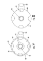
- FIG. 19 is a top plan view of a base portion of the feed mechanism of the present invention.
- FIG. 20 is a bottom plan view of a base portion of the feed mechanism of the present invention.
- FIG. 21 is a bottom plan view of an alternate base portion of the feed mechanism of the present invention.
- FIG. 22 is a top plan view of an alternate base portion of the feed mechanism of the present invention.
- FIG. 23 is an isometric view of an alternative drive shaft of a drive mechanism for a paintball loader of the present invention.
- FIG. 24 is an isometric view of a base portion corresponding to the shaft of FIG. 23 .
- FIGS. 25 and 26 are exploded isometric views of a still further embodiment of a drive mechanism according to the present invention.
- FIG. 27 is a side sectional view of the feed mechanism shown in FIGS. 25 and 26 .
- FIG. 28 is a sectional view taken along line 28 - 28 in FIG. 27 .
- FIG. 29 is a bottom perspective view of an alternate feed mechanism.
- FIG. 30 is a top view of a feed mechanism of the present invention depicting rotation.
- FIG. 31 is an exploded view of loader utilizing the feed mechanism of the present invention.
- FIG. 32 is an exploded view of the drive assembly of the feed mechanism of the present invention.
- FIG. 33 is an isometric view of the feed mechanism of the present invention.
- FIG. 34 is an exploded view of the feed mechanism of FIG. 33 .
- FIG. 35 is another exploded view of the feed mechanism of FIG. 33 .
- FIG. 36 is an isometric view of the feed mechanism of FIG. 33 shown with its cover removed.
- FIG. 37 is an isometric view of the feed mechanism of FIG. 33 shown with its feeder removed, exposing the spring element.
- FIG. 38 is an isometric view of the feed mechanism of FIG. 33 shown with its spring removed.
- FIG. 39 is a section view of the feed mechanism of FIG. 33
- FIG. 40 is an isometric view of an exemplary carrier magnet coupled to a drive shaft.
- FIGS. 41 a - e show isometric views of various drive configurations of the feed mechanism of the present invention.
- FIG. 42 is a plain view of a kit for a drive mechanism of the present invention, including interchangeable drive components.
- FIG. 43 is a side view of the paintball loader and feed system of the present invention operatively attached to a paintball marker.
- FIG. 44 is an exploded view of an alternate embodiment of the drive assembly of the feed mechanism of the present invention.
- binding element refers to either a magnet or a magnetically attractable element.
- a “magnetically attractable element” can be any element that is attracted to a magnet including, but not limited to, ferromagnetic materials such as iron, nickel, cobalt, neodymium, etc.
- feeder feed mechanism
- impeller are used interchangeably to refer to any apparatus that impels, moves, pushes, agitates, or otherwise mixes projectiles within a loader or hopper, such as an agitator, arms, fins, paddles, paddle arms, spokes, drive cones, carriers, including, but not limited to, those shown and described in U.S. Pat.
- FIG. 1 is a side elevational view of a paintball loader 10 attached to a representative paintball gun 12 (illustrated in phantom).
- the paintball gun 12 includes a main body 14 , a compressed gas cylinder (gas tank) 16 , a barrel 18 , and a grip portion 20 .
- the paintball gun also includes an inlet tube 22 (also called a feed neck) leading to a firing chamber 23 (or breech) in the interior of the main body 14 , and a trigger 24 .
- the compressed gas cylinder 16 is typically secured to a rear portion of the paintball gun 12 .
- the compressed gas cylinder normally contains CO 2 or NO 2 , although any compressible gas may be used.
- the paintball loader 10 includes a loader body 100 forming an interior area 104 .
- the loader body 100 may be divided into an upper portion 106 and a lower portion 108 .
- an exit portion 110 such as an opening, leads from the lower portion 108 of the loader body 100 to an outfeed tube 112 , although the exit portion 110 may be positioned at another location in the loader body 100 .
- the exit portion 110 is positioned adjacent the inlet tube 22 of the compressed gas gun 12 .
- the paintball loader 10 includes a motor 66 .
- the motor 66 may be in communication with a controller 114 and/or microprocessor 116 for controlling at least one operation of the loader 10 .
- At least one sensor 118 may be provided in communication with the motor 66 , controller 114 and/or microprocessor 116 , or any combination of those, for detecting the presence or absence of projectiles 62 in the exit portion 110 or outfeed tube 112 of the loader 10 , or positioned at other locations within or about the loader body 100 .
- a power source such as a battery 117 may be provided for powering the motor 66 , controller 114 , microprocessor 116 , or any combination thereof.
- a drive mechanism 26 includes a drive shaft 36 that rotates about a central axis 64 .
- the drive shaft 36 is coupled at its first end 67 to a motor 66 for rotating the drive shaft 36 , which may be an electrical motor, a stepper motor, a wind up or spring operated motor, or any other means for rotating or otherwise operating the drive mechanism 26 .
- the second end or upper portion 68 of the drive shaft 36 includes at least one binding element 32 .
- the binding element 32 is a magnet or a magnetically attractable insert, such as a ferrous metal, or other metal attracted to a magnet.
- the feed mechanism 40 is positioned adjacent the second end or upper portion 68 of the drive shaft 36 .
- the feed mechanism 40 may include arms 98 (fins, paddles, or other extensions) such as shown in FIGS. 2-3 , adapted for mixing or moving paintballs contained with a paintball loader 10 .
- the feed mechanism 40 includes a lower portion 136 including at least one second binding element 138 .
- the second binding element 138 may be a magnet of different polarity as the binding element 32 (if the binding element 32 is a magnet), or may be a magnetically attractable insert (if the binding element 32 is a magnet), or may be a magnet of any polarity (if the binding element 32 is a magnetically attractable insert).
- the feed mechanism 40 includes an opening 140 for receiving a screw 142 .
- the screw 142 is preferably sized smaller than the opening 140 , and is received in a threaded opening 144 in the upper portion 68 of the drive shaft 36 .
- the feed mechanism 40 is free to rotate about the screw 142 .
- a bushing (or bearing) 146 and/or washer 148 may be provided for assisting free rotation of the feed mechanism 40 . It is appreciated that a thinner diameter portion extension of the drive shaft 36 may extend though the opening 140 , and may be affixed in place with a screw or other connection means.
- the drive shaft 36 When the motor 66 operates the drive shaft 36 , the drive shaft 36 will rotate in either a clockwise or counterclockwise direction about the central axis 64 .
- the binding element 32 and second binding element 138 will have a magnetic attraction to each other.
- the binding element 32 when the drive shaft 36 rotates, the binding element 32 will impart (or have imparted upon it) a magnetic force (adhesion force) on the second binding element 138 , that will rotate in tandem the feed mechanism 40 when there are no jammed paintballs in the paintball loader 10 .
- the drive shaft 36 will continue to rotate. With the feed mechanism 40 unable to continue rotation, the binding element 32 will rotate past the second binding element 138 of the feed mechanism 40 when the force of the motor 66 on the drive shaft 36 cannot overcome the force holding the feed mechanism 40 in place. In this manner, the motor 66 will not be damaged, and the feed mechanism 40 will not be forced to break or otherwise rupture paintballs that cannot be agitated.
- the present invention provides for a magnetic clutch system.
- the binding element 32 will again come into proximity to the second binding element 138 .
- the binding element 32 and second binding element 138 can be positioned at any location on or about the drive shaft 36 or the feed mechanism 40 to permit the binding element 32 and second binding element 138 to come into proximity and be in position so that a magnetic attraction occurs between the binding element 32 and second binding element 138 .
- a binding element 32 may be positioned or otherwise formed in a side wall 150 of the drive shaft 36 , facing outwardly from the central axis 64 .
- the feed mechanism 40 may have the second binding element 138 positioned facing toward the opening 140 , or binding elements placed in the bottom portion of the feed mechanism 40 ( FIG. 50 ).
- the drive mechanism 26 will operate as previously with the magnetic clutch action described. Alternately, a portion of the drive shaft 26 can be formed from a magnet or magnetically attractable insert.
- the second end 68 of the drive shaft 36 may include at last one or a plurality of binding elements 32 , as shown in FIGS. 6A and 6B , top plan views of different embodiments of the drive shaft 26 .
- the feed mechanism 40 may include at last one or a plurality of binding elements 138 , as shown in FIGS. 7-8 .
- the operation of the drive mechanism 26 can be controlled by varying the number of binding elements, the strength of any magnets, and the distance between the binding element 32 and the second binding element 138 , for example.
- the motor 66 may be controlled by the controller 114 such as an electronic control circuit that may include a microprocessor 116 .
- the paintball loader 10 may include at least one sensor 118 in communication with the motor 66 and/or controller 114 for detecting paintballs, such as an electromechanical sensor or switch, an optical sensor, and infrared (IR) sensor, a sound or shockwave sensor, or any other sensor as are known in the art.
- the controller 114 can control rotation of the motor 66 in either direction, providing for a reversible feed mechanism 40 operation.
- the drive mechanism 26 includes a drive shaft 36 having an upper portion 68 that is contoured or angled.
- the lower portion 136 of the feed mechanism 40 is contoured complementary to the contour of the upper portion 68 of the drive shaft 36 .
- a spring 152 is provided between the attachment screw 142 and the feed mechanism 40 .
- At least one binding element 32 is positioned proximate the upper portion 68 of the drive shaft 36
- at least one second binding element 138 is positioned proximate the lower portion 136 of the feed mechanism 138 , as previously described.
- the feed mechanism 40 is adapted for movement above and below its originally plane of movement if a projectile jam is encountered, in addition to the rotational movement of the feed mechanism 40 being driven by the drive shaft 36 .
- the spring 152 biases the feed mechanism 40 back to its original position.
- An additional or alternate 146 spring can be provided between the upper portion 68 of the drive shaft 36 and the lower portion 136 of the feed mechanism 40 .
- FIGS. 10-20 show an alternate embodiment of a drive mechanism according to the present invention for use in a paintball loader 10 .
- drive mechanism includes a clutch plate 28 , shown in detail in FIGS. 12 and 14 - 16 , having a keyed opening 30 therethrough, and including at least one binding element 32 .
- the binding element 32 is a magnet, but may also be a magnetically attractable insert.
- the clutch plate 28 may include one or a plurality of binding elements 32 , as shown in FIGS. 14 and 15 .
- the clutch plate 28 is preferably formed as a disc 34 with the keyed opening 30 shaped to accept a keyed portion 38 of a drive shaft 36 , as shown in FIG. 13 .
- the opening 30 may be any shape for accepting the drive shaft 36 , as shown in FIGS. 14 and 15 , so long as the keyed portion 38 of the drive shaft 36 can rotate the plate 28 .
- the clutch plate 28 can be any size and/or shape suitable for its purposes as disclosed below, such as the alternate embodiment shown in FIG. 16 , and may be comprised of any metal, plastic, or other suitable materials.
- the clutch plate 28 is formed from a plastic, or other non-metallic, non-magnetic material. It should be understood that the clutch plate 28 can also be permanently affixed and part of the drive shaft 36 .
- the plate 28 may be formed entirely from the material comprising the binding element 32 , such as a magnetic or magnetically attractable material.
- the plate 28 may also be formed with the binding elements 32 fashioned as rectangular inserts, as shown in FIGS. 12 and 14 - 16 .
- the binding elements 32 may be removable, or permanently affixed to the plate 28 . Through the variation of the binding elements, one is able to adjust the attractive forces to correspond with the specific properties of the projectile.
- FIGS. 13 , 17 , and 18 show a drive shaft 36 for providing movement to agitate, mix or move the projectiles 62 in the loader 10 .
- the drive shaft 36 is adapted to rotate about its central axis under the force of a motor 66 to which it is coupled at its first end 67 , preferably an electric, battery operated motor, although any motor is acceptable.
- the drive shaft 36 has an upper portion 68 , which is preferably substantially circular and includes a threaded opening 144 for accepting a screw 142 , and a lower keyed portion 38 shaped to engage the opening 30 of the clutch plate 28 .
- the drive shaft 36 may be constructed of various materials, such as molded plastic or metal, and is sized and shaped so that it is capable of passing through the opening 16 of the clutch plate 28 and the openings 22 of the paintball feed mechanism 40 .
- FIGS. 17-18 show a paintball feed mechanism 40 according to one embodiment of the present invention.
- the feed mechanism 40 shown may be similar in design and operation to the active feed assemblies disclosed in U.S. Pat. No. 6,792,933 and U.S. Pat. No. 6,701,907, the entire contents of which are incorporated fully by reference herein, which are used in connection with the well known HALO B® or EMPIRETM RELOADERTM B paintball loaders. It is noted that the present invention may be used with, in place of, or as an adjunct to any other feed mechanism, agitator, paddle or impeller of any kind.
- the feed mechanism 40 includes an impeller portion 42 , and a base portion 44 .
- the impeller portion has an opening 46 therethrough and the base portion 44 has an opening 48 therethrough.
- the openings 46 , 48 are sized to accept a portion of the drive shaft 36 , and to permit the feed mechanism 40 to freely rotate about the drive shaft 36 .
- At least one binding element 50 preferably located on, formed in, inserted into, or affixed to the bottom surface 52 of the base portion 44 .
- FIGS. 11 and 17 - 20 show the base portion 44 substantially the same size and shape as the clutch plate 28 .
- the feed mechanism 40 may be larger or smaller than the clutch plate 28 or of a different shape.
- the feed mechanism 40 can be provided as a single unit, with at least one binding element 50 positioned at any position to be attracted magnetically to the binding element 32 of the clutch plate 28 , such as on a lower wall 82 including one or a plurality of binding elements 50 , as shown in FIG. 29 .
- the base portion 44 of the feed mechanism 40 may be formed as an open cylinder having an upstanding annular wall 54 and a floor 58 , as shown in FIGS. 11 and 17 - 19 .
- the base portion 44 is positioned below the impeller portion 42 .
- a gap or space 56 may be provided between the floor 58 of the base portion 44 and the lower face 60 of the impeller portion 42 .
- the base portion 44 is formed as an open cylinder 88 , having a base or floor 90 and an annular wall 92 .
- the floor 90 may be provided with at least one or a plurality of cavities 94 sized and shaped to receive corresponding binding elements 50 .
- the binding elements 50 can be sized and shaped to removably engaged the cavities 94 whereby the binding elements 50 will be sized to securely fit within the cavities 94 a shown in FIGS. 11 and 19 - 20 , so that they will not fall out of the cavities 94 during operation.
- magnetic attractive forces between the at least one magnetic portion of the drive shaft and the at least one magnetic or magnetically attractable portion of the feed mechanism can be varied and regulated. In this way the magnetic force is less than a rupture force of a paintball adapted to be loaded by the feed mechanism.
- the feed mechanism has a spring-assist or spring-loaded component for feeding projectiles.
- a first spring contact wall 72 projects from the annular wall 54 of the base portion 44 into the gap 56 .
- a second spring contact wall 74 projects from the lower face 60 of the impeller portion 42 .
- a spring 76 preferably a torsion spring, is positioned within the gap 56 , and has a first end 78 positioned adjacent the first spring contact wall 72 , and a second end 80 positioned adjacent the second spring contact wall 74 . It should be understood however, that any suitable biasing member can be used in place of the spring, for example, an elastomer.
- the spring 76 will be compressed due to the relative movements of the first end 78 of the spring 76 against the first spring contact wall 72 , and the second end 80 of the spring 76 against the second spring contact wall 74 .
- the spring 76 compresses, storing potential energy for driving projectiles. This provides a “spring-loaded” drive mechanism, where spring tension is provided for force feeding projectiles during operation when the feed impeller portion 42 is free to move.
- FIGS. 17-19 show an embodiment of the drive mechanism 26 of the present invention in an exploded view of the various components.
- the base portion 44 is positioned between the impeller portion 42 and the clutch plate 28 . Where a spring is used, the spring 76 is positioned within the gap 56 .
- the drive shaft 36 extends through the drive mechanism opening 30 and the respective openings 46 , 48 of the base portion 44 and impeller portion 42 .
- a screw 142 is threaded into the opening 144 of the drive shaft 36 , and the screw 142 preferably has a head larger than the diameter of the opening 46 , so that the feed mechanism 40 is held in place.
- the keyed portion 38 of the drive shaft 36 engages the keyed opening 30 of the clutch plate 28 , such that rotation of the drive shaft 36 by the motor 66 produces rotation of the clutch plate 28 .
- the screw 142 is threadably engaged to the drive shaft 36 , the screw 142 is effectively an extension of the drive shaft 36 running through the opening 46 in the feed mechanism 40 .
- the feed mechanism 40 is free to rotate about the screw 142 .
- binding element 32 of the clutch plate 28 is positioned to provide an attractive magnetic force when adjacent the binding element 50 of the base portion 44 .
- the binding element 32 and binding element 50 may be any combination of elements producing magnetic attraction between them, for example: binding element 32 is a magnet of a first polarity, and binding element 50 is a magnet of a second an opposite polarity; binding element 32 is a magnet, and binding element 50 is a magnetically attractable insert attractable to the magnet; and/or, binding element 32 is a magnetically attractable insert, and binding element 50 is a magnet.
- the attractive magnetic force (also referred to herein as the “adhesion force”) between the binding elements 32 , 50 is preferably such that when the drive shaft 36 rotates and turns the clutch plate 28 , the magnetic attraction between the binding element 32 and the binding element 50 correspondingly rotates the base portion 44 of the feed mechanism 40 , which in turn rotates the impeller portion 42 of the feed mechanism 40 . If a spring 76 is used, the rotation of the base portion 44 will be translated to the impeller portion 42 via movement of the first spring contact wall 72 against the end 78 of the spring 76 , as described in greater detail above.
- the rotation of the clutch plate 28 drives the feed mechanism 40 by magnetic attraction between the binding elements 32 , 50 .
- the projection 84 of the impeller portion 42 may encounter a stationary or jammed projectile 62 .
- the motor 66 will continue to rotate the drive shaft 36 , which will turn the clutch plate 28 .
- the binding element 32 of the clutch plate 28 will “slip” or otherwise move past the binding element 50 on the base 44 .
- the clutch plate 28 will continue to rotate independently of the feed mechanism 40 .
- the binding element 32 will be magnetically attracted to the binding element 50 of the base 44 when the binding elements 32 , 50 are in proximity such that they are magnetically attracted.
- the feed mechanism 40 is free to again rotate (such as when the paintball stack is moving, or a jammed projectile 62 is dislodged) the binding element 32 will again attract the binding element 50 , and the feed mechanism 40 will rotate to propel or otherwise mix projectiles 62 .
- the binding elements 32 , 50 should be selected such that the magnetic force (adhesion force) between the binding elements 32 , 50 is strong enough to overcome the biasing force of the spring 76 on the walls 72 , 74 , yet will “slip” when the spring 76 is compressed or otherwise wound to a certain selected degree or amount.
- a paintball stack may form, for example, when a paintball marker to which a paintball loader is attached has indexed projectiles 62 in the outfeed tube and feed neck 22 , but the paintball marker 12 is not being fired. Projectiles 62 back up forming a stack.
- the base portion 44 When the projection 84 contacts the stationary paintball stack, the base portion 44 will continue to turn, by way of example, counter-clockwise, if the feeding direction is counter-clockwise. This will compress and increase tension in the spring 76 as the base portion 44 rotates relative to the impeller portion 42 . However, it may be desired that the drive mechanism will slip (the adhesion force between the binding elements 32 , 50 is overcome) when the spring 76 is compressed to a certain degree or amount, which may be a user selected degree or amount.
- the binding elements 32 , 50 may be selected such that, when the base portion 44 rotates a certain angular distance relative to the point of contact between the projection 84 and the paintball stack, the binding elements 32 , 50 slip. This is shown schematically in FIG. 30 , which is a schematic bottom view of a projection 84 contacting a paintball stack.
- the angular distance can be selected by a user, and can be any angular distance, with a preferred distance being approximately about 340 to 360 degrees of rotation
- a second binding element 32 may be positioned on the clutch plate 28 , to “catch” or attract the base portion 44 as it unwinds, so that the spring 76 does not fully decompress. In this manner, tension is retained in the spring 76 for propelling projectiles 62 once the stack begins to move. In addition, the slipping action of the drive mechanism will not force, break or otherwise crush or rupture projectiles.
- a plurality of binding elements 32 maybe provided on a clutch plate 28 . Each of the binding elements 32 will attract the binding element 50 , as the clutch plate 28 rotates.
- the force necessary to overcome the magnetic attraction between the binding elements 32 and 50 can be adjusted by utilizing magnets of varying magnetic strengths.
- the size of the magnets used for the binding elements 32 , 50 can be varied.
- the distance between the clutch plate 28 and the bottom surface 52 of the feed mechanism 40 can also be varied, thus adjusting the interaction of the magnets and/or magnet and magnetically attractable inserts.
- a shim or other divider piece can be formed between the clutch plate 28 and the bottom surface 52 of the feed mechanism 40 .
- the spring 76 can further be selected having a particular tension.
- the number of binding elements 32 , 50 can be varied, such as illustrated in FIGS. 14-15 and 17 - 18 .
- a user of a paintball loader according to the present invention can adjust the operation by selectively inserting and positioning binding elements 50 within the cavities 94 .
- a cylinder 88 can be provided with a preselected number of binding elements 50 , attached or affixed to, formed in, or formed on the floor 90 of the cylinder 88 .
- Several cylinders 88 may be included with a paintball loader kit, incorporating different numbers of binding elements 32 that may be user selected, based on operating conditions such as paintball shell brittleness. Similarly, as shown in FIGS.
- the clutch plate 28 may be formed including at least one or a plurality of binding elements 32 .
- the binding elements 32 can be preformed on or affixed to the clutch plate 28 , or may be held within cavities formed in the clutch plate 28 .
- Several drive mechanism bases 28 having different binding element 32 configurations may be provided in a kit with a paintball loader according to the present invention.
- the drive system 34 operates as a clutch system to avoid or manage projectile jams, and to provide fine-tuning of paintball loader operation. If the feed mechanism 40 stops or slows its rotation relative to the rotation of the drive mechanism 26 and drive shaft 36 due to a jam, the system will not chop or otherwise break projectiles. Projectiles may back-up or otherwise block the outlet tube, and interfere with the rotation of the projections 84 , which slows or stops the feeder 36 . In the many loaders currently known in the art the feeder 36 continues to try to rotate with the force of the motor, and therefore, the projections 84 continue to try to impel projectiles through the loader. The continued impelling force from the feeder on the jammed projectiles can break the projectiles, the feeder 36 , the impellers 39 , and/or other parts of the loader.
- the feed mechanism 40 when the feed mechanism 40 stops rotating, the force of the rotation of the drive shaft 36 on the clutch plate 28 overcomes the magnetic attraction between the binding elements 32 , 50 . This causes the feed mechanism 40 to move relative to, or slip past the base portion 44 . The drive mechanism 26 no longer rotates the feed mechanism 40 , which therefore, no longer rotates the feeder 36 . Thus, the feeder impellers 39 stop moving against the stationary, jammed or blocked projectiles.
- an entire surface of the clutch plate 28 may be formed as a binding element, such as a magnet or a magnetically attractable material.
- an entire surface of the floor 58 of the base portion 44 may be formed as a binding element, such as a magnet or a magnetically attractable material.
- the drive shaft 36 may be formed to act as an additional slip clutch mechanism. Such an embodiment may be used in addition to the previously disclosed embodiments, or may replace the clutch plate 28 and base portion 44 as previously described.
- At least one binding element 120 which may be a magnet or magnetically attractable insert, is provided on or within the drive shaft 36 , as shown in FIG. 23 .
- a central portion 122 of the base portion 44 is adapted to rotate independently from the other portions of the base portion 44 .
- the central portion 122 includes at least one binding element 124 , which may be a magnet or magnetically attractable insert, positioned adjacent an annular wall 128 of the central portion 122 .
- Binding element 120 and binding element 124 are selected so that they are magnetically attracted to each other.
- the upper surface 130 of the floor 58 of the base portion further includes at least one binding element 132 , which may be a magnet or magnetically attractable insert. Binding element 132 is selected so that it is magnetically attracted to binding element 124 .
- a second slip clutch mechanism is disclosed.
- the binding element 120 of the drive shaft 36 will rotate when the drive shaft 36 is rotated by the motor 66 .
- Binding element 120 will magnetically attract binding element 124 , thus rotating the central portion 122 through magnetic attraction.
- the binding element 124 will in turn attract binding element 132 , thus turning, or assisting in turning, the balance of the base portion 44 .
- binding elements 120 , 124 , 132 can be use as adjuncts to the previously described binding elements 32 , 50 .
- binding element 32 will magnetically drive binding element 50 , acting as a first magnetic slip clutch system
- binding element 120 will magnetically drive binding element 124 , which in turn will magnetically drive binding element 132 , acting as a second magnetic slip clutch system. Any combination and positioning of the various binding elements may be used to achieve desired operation of the drive mechanism 26 of the present invention.
- FIGS. 27 and 28 A cross section of the feed portion 40 of the feed device 26 is shown in FIGS. 27 and 28 .
- the base portion 44 houses the spring 76 having first and second ends 78 , 80 that are biased against a first contact wall 72 of the base portion and a second contact wall 74 of the impeller portion 42 , respectively. It should be understood that other biasing members can also be used, for example, an elastomer.
- spring 76 When sufficient tension is present in spring 76 , the impeller portion 42 is rotated such that impeller projections 84 contact a projectile 62 to urge it into a feed tube 112 of a loader 10 and into a breech of a gun 12 .
- the clutch plate 28 can be eliminated, and the drive shaft 36 will act as the clutch system for the drive mechanism 26 .
- the central portion 122 can be eliminated, and the binding element 120 of the drive shaft 36 can be selected to directly magnetically attract the binding element 132 of the upper surface of the floor 130 .
- FIG. 31 is an exploded view of another embodiment of an exemplary paintball loader 200 of the present invention.
- the loader 200 includes a body 219 which may include left and right shell portions 202 , 204 which, when joined, create an interior paintball chamber 203 for the storage of paintballs.
- the loader 200 includes a pivotally attached lid 206 which provides an opening through which paintballs are added to the interior chamber 203 of the loader 200 for feeding to a paintball marker.
- a floor insert 208 provides a bottom surface for the interior paintball chamber 203 and includes an opening through which paintballs move from the interior paintball chamber 203 into a cup assembly 201 .
- the contours of the interior surfaces of the shells 202 , 204 may be formed to securingly mate with the cup assembly 201 , although it is appreciated that the cup assembly can be attached to interior of the loader 200 through any suitable means.
- the cup assembly 201 features a catch cup 212 positioned below the opening in the floor piece 208 that accepts paintballs from the interior paintball chamber 203 of the loader 200 .
- a feed mechanism 210 is placed into the catch cup 212 , with its shaft 211 inserted through the cup 212 . In use, the feed mechanism 210 is designed to feed projectiles from the catch cup 212 into the exit portion 281 of the outfeed tube 222 .
- a motor 226 is provided to drive the feed mechanism 210 and may drive the feed mechanism via drive system including a gear, gears or gearbox 224 .
- the motor 226 is preferably mounted adjacent the catch cup 212 as shown in FIG. 32 and preferably comprises a DC motor, although any suitable motor or driving mechanism (such as a stepping motor) may be utilized without departing from the scope of the present invention.
- the motor 226 may be controlled by a controller or circuit board 207 ( FIG. 31 ), such as electronic control circuitry that may include a microprocessor 251 .
- the paintball loader 200 may also include at least one sensor 252 in electrical or wireless communication with a motor 226 and/or controller 207 for detecting paintballs (such as by movement or position, for example) and/or movement or position of the feed mechanism 210 .
- the sensor 252 may be an electromechanical sensor, a switch, an optical sensor, a break beam sensor, and infrared (IR) sensor, a reflective sensor, a sound or shockwave sensor, a piezoelectric sensor, or any other sensor as are known in the art for detecting paintball movement or feeder movement.
- the controller 207 can control rotation of the motor 226 in any direction, providing for a reversal of the rotation of the feed mechanism 210 enhancing its ability to clear projectile jams.
- the user may actuate the controller 207 via a switch plate 209 locate on the exterior if the loader 200 , such as by pressing a button 282 on the switch plate 209 .
- at least one power source such as a battery 213 is provided to power the motor and/or additional controls or sensors.
- the battery 213 is preferably stored inside of the loader 200 , and features a cover 205 to facilitate easy removal and replacement.
- the gearbox 224 comprises a belt and pulley system having a first pulley 228 , a drive belt 234 , and a second pulley 232 .
- the second pulley 232 comprises an integral pinion gear 233 configured to drive a spur gear 236 .
- the shaft 211 of the feed mechanism 210 is preferably keyed into the spur gear 236 by means of a profiled portion 216 of the shaft 211 and complementary profiled opening 217 of the spur gear 236 , whereby the rotation of the spur gear 236 rotates the feed mechanism 210 .
- this combination belt drive and gear arrangement could be replaced with any other suitable means to transmit the rotational force of the motor 226 to the feed mechanism 210 including direct, gear, belt, or fluid drives. It is also envisioned that the size of respective pulleys 228 , 232 and gears 233 , 236 could be varied in order to change the rotational speed of the feed mechanism 210 , thereby varying the feed rate of the balls into the marker, as well as the torque delivered by the shaft 211 .
- a motor 226 may also directly drive the shaft 211 of the feed mechanism 210 , without the use of additional gears or belts. Any arrangement for coupling the motor to the drive shaft to operate the drive shaft is contemplated as included within the scope of the present invention.
- the shaft 211 of the feed mechanism 210 may be supported on either side of the spur gear 236 by bushings or bearings 237 .
- one bearing 237 is positioned in or between each of the catch cup 212 and a gearbox cover 214 , and the spur gear 236 .
- the gearbox cover 214 preferably provides a generally sealed enclosure for the gear box assembly 224 and motor 226 , protecting the components from dirt, debris, and other objects which could potential jam the mechanism and/or inhibit its function.
- a cover 241 may be utilized to provide access to the gearbox assembly 224 to facilitate maintenance, inspection, or any other suitable use.
- the gearbox cover 214 is preferably secured to the bottom of the catch cup 212 by fasteners 238 .
- the fasteners 238 comprise standard bolt and nut 239 combinations, however it is envisioned that other suitable attachment means may be utilized.
- dowel pins 244 may be used in combination with the fasteners 238 to ensure the proper orientation of the gear box cover 214 with the catch cup 212 .
- An anti-jamming or manual winding wheel 242 is preferably provided on an end of the shaft 211 accessible outside of the loader 200 in order to provide a means to manually rotate the feed mechanism 210 , thereby facilitating the clearing of any jams in the system, or otherwise rotating the drive shaft based on a user's needs.
- Such an anti-jamming and/or manual reversing mechanism is disclosed in U.S. Pat. No. 7,343,909, the entire contents of which is incorporated by reference herein.
- the wheel 242 is preferably keyed to the shaft 211 at a lower portion 216 and is secured by use of a retaining clip 243 , however, any suitable means of connection may be used.
- Additional means to prevent jamming include resiliently mounted beads 218 and/or an anti-jamming deflection spring 219 mounted to the interior of the loader 200 , adjacent the outfeed tube 222 .
- these elements are mounted to an inner surface of the catch cup 212 adjacent the exit portion 281 , and aid in ensuring the proper positioning the projectiles onto the lip 253 of the feed mechanism 210 .
- FIG. 43 illustrates one embodiment of the integration between the loader 200 and a paintball marker 300 .
- the paintball marker 300 includes a main body 302 , a barrel 304 , a grip portion 306 , an inlet tube 308 , a firing chamber 310 , and a trigger 312 .
- the marker 300 is adapted it receive compressed gas from a source of compressed gas such as a CO2 or NO2 tank, as is will known in the art.
- the projectiles contained in the loader 200 are driven by the feed mechanism 210 into the outfeed tube 222 .
- the outfeed tube 222 is clamped using clamp 283 or other attachment means to the inlet portion 308 of the marker 300 .
- the outfeed tube 222 feeds the projectiles into the inlet portion 308 of a paintball marker 300 . From the inlet portion, the projectiles move into the firing chamber (or breech) where they are fired from the marker under the force of compressed gas.
- cup assembly 201 could be integrated into a loader 200 specifically configured to accept such an assembly, or in an alternate embodiment, may be installed into an existing loader as part of a retrofitted kit. This embodiment would allow a user to enhance the performance of their present loader without requiring the purchase of the entire loader and cup arrangement.
- the cup assembly 201 including the feed mechanism 210 , the gearbox 224 and the inlet cup 222 would be placed into the interior of an existing loader, and securely attached thereto.
- FIG. 33 is an isometric view of a feed mechanism 210 of the present invention completely assembled.
- the feed mechanism 210 comprises a feed mechanism carrier or feeder 220 and separate cover 280 that is capable of movement independent of the feeder 220 .
- the feed mechanism 210 shown may be similar in design and operation to the feed assemblies disclosed in U.S. Pat. No. 6,792,933 and U.S. Pat. No. 6,701,907, the entire contents of which are incorporated fully by reference herein, which are used in connection with the well known HALO B® or EMPIRETM RELOADERTM B paintball loaders. It is noted that the present invention may be used with, in place of, or in addition to any other feeder, feed mechanism, agitator, paddle, wheel or impeller of any kind.
- the feed mechanism 210 comprises a shaft 211 which may include a bearing 237 , which is coupled to a motor.
- a first plate 230 is keyed to matingly engage a keyed portion 215 of the drive shaft 211 so that rotation of the drive shaft 211 rotates the first plate 230 .
- the first plate 230 comprises at least one or a plurality of openings 235 that are configured to receive binding elements 250 .
- the openings 235 may receive either magnets, or magnetically attractable inserts.
- the openings 235 receive magnets which fit into openings.
- a second plate 240 formed from a magnetically attractable material is positioned about the drive shaft 211 adjacent the first plate 230 , and preferably above the first plate 230 , as shown in FIG. 35 .
- the second plate 240 is magnetically attractable to the binding elements 250 of the first plate 230 , and is preferably formed from a ferrous metal or a magnetic material with a polarity opposite the binding elements 250 so that there is a magnetic attraction between the binding elements 250 and the second plate 240 .
- any combination of magnetic material, ferrous metal, or other suitable materials may be utilized in either the first or second plates 230 , 240 without departing from the scope of the present invention.
- the binding elements 250 could be magnetically attractable inserts formed of a ferrous metal
- the second plate 240 could be formed from a magnet attractable to the binding elements 250 .
- the second plate 240 is not keyed to match the keyed portion 215 of the drive shaft 211 , and is therefore free to rotate independent of the shaft 211 .
- the second plate 240 may be of any shape. Illustrative shapes are shown in FIGS. 40-42 and will be described in greater detail herein.
- a housing 260 is positioned about the drive shaft 211 , and is preferably positioned above the second plate 240 as shown in FIG. 35 .
- the housing 260 preferably includes a lower portion 254 having an underside 255 ( FIG. 39 ) with a space configured to receive the second plate 240 such that the housing 260 will rotate when the second plate 240 is rotated by the drive shaft 211 .
- the second plate 240 and the lower portion 254 of the housing 260 have corresponding shapes, such that the second plate mechanically engages the housing 260 when fitted into the space of the underside 255 , such that movement of the second plate 240 will move the housing 260 .
- the housing 260 has an outer annular wall 257 and an inner annular wall 256 forming a receiving area 258 ( FIGS. 37-39 ) configured to receive, for example, a spring 270 or other biasing element.
- An extension wall 265 positioned within the receiving area 258 of the housing 260 acts as a contact point for one of the ends 275 of the spring 270 .
- the other end 276 of the spring 270 abuts a flange 226 ( FIG. 39 ) extending from a lower portion 259 of the feeder 220 .
- the spring 270 or another biasing member provides may provide biasing force on the feeder 220 .
- the rotational force of the housing 260 will be translated via the spring 270 to the feeder 220 .
- the first plate 230 acts as a binding element or magnet carrier or holder.
- the first plate 230 provides for the potential for various configurations of magnets 250 or binding/attraction points.
- the first plate 230 has a six-pointed star shape, which six receiving openings 261 adapted to receive magnets at each point of the star shape in an outer configuration, and an inner configuration of six receiving openings 262 adapted to receive magnets.
- the second plate 240 is magnetically attracted to the binding elements 250 of the first plate 230 . Accordingly, when the drive shaft 211 rotates the first plate 230 , the second plate 240 will rotate due to the magnetic attractive force between the plates.
- the magnetic attraction force between the binding elements 250 of the first plate 230 and the second plate 240 is, in part, a function of the shape of the second plate 240 .
- Different binding element 250 configurations (such as by selective placement of a selected number of binding elements 250 in selected openings 261 , 262 in the first plate 230 ) and different second plate 240 shapes will interact with differently positioned binding elements 250 to produce different magnetic attraction forces when the drive mechanism of a paintball loader of the present is in operation.
- the magnetic attractive forces between the binding elements 250 of the first plate 230 and the second plate may be selectively varied. This may vary the “magnetic moment,” which is a measure of the torque exerted on a magnetic system (as a bar magnet or dipole) when placed in a magnetic field and that for a magnet is the product of the distance between its poles and the strength of either pole.
- the attraction area between the first plate 230 and the second plate 240 can be considered the total area where binding elements 250 can exert a magnetic attraction force on the second plate 230 at a given time.
- the second plate 240 as shown in FIG. 41 a generally has a similar six-pointed star configuration as the exemplary first plate 230 .
- This six-pointed plate 240 when filled with binding elements, may maximize the magnetic attraction force between the first plate 230 and the second plate, providing the largest attraction area. That is, the magnetic force is maximized as a result of utilizing a plate 240 which incorporating several binding elements 250 over an increased attraction area.
- the binding elements 250 in the outer ring O of the first plate 230 will “release” or “slip,” and will again “catch” (come adjacent to and be attracted to) the next point of the second plate after moving through an arc of about sixty degrees.
- the first plate 230 and the second plate 240 will have the greatest attraction area each about sixty degrees of rotation of the first plate 230 relative to the second plate 240 , with an attraction between all points of the star shapes of the plates 230 , 240 .
- Another exemplary plate 240 ′ shown in FIG. 41 b , is generally triangular in shape, and therefore the attraction area is reduced as a result of the plate 240 ′ configured to be positioned adjacent less binding elements 250 when the first plate 230 is in position holding (through magnetic force) the second plate 240 , in this example, with three binding elements 250 of the outer ring O adjacent the points of the triangular shape at a time.
- the first plate 230 releases the second plate 240 or slips, the first plate 230 will travel along an arc of sixty (60) degrees before a next binding element 250 of the outer ring O is adjacent a point of the triangle of the second plate 240 ′ in the case of binding elements 250 being inserted into every hole 261 (as shown in FIG. 41 b ), or through an arc of about one-hundred and twenty (120) degrees, if the every other hole 261 of the outer ring O is left empty.
- exemplary shaped second plates 240 and 240 ′ have central portions that will remain adjacent any binding elements 250 of the inner ring portion I of the first plate 230 , even as the binding elements 250 of the outer ring portion O release or slip.
- the binding elements 250 of the inner ring portion I provide a substantially continuous magnetic attraction force between the first plate 230 and the second plate 240 , even as the first plate 230 moves relative to the second plate 240 .
- Exemplary plate 240 ′′ shown in FIG. 41 c has an elliptical shape and provides two portions attractable to binding elements 250 of the outer ring portion O, as well as a central portion that is attractable to at least some of the binding elements 250 of the inner ring portion I.
- This configuration provides less of an attraction area than the arrangement described in FIG. 41 b as a result of additional holes 261 or binding elements 250 positioned non-adjacent the plate 240 ′′.
- the arc distance that the first plate 230 travels through between magnetic “slips” and magnetic “catches” may be varied between about sixty (60) degrees, and about one-hundred eighty (180) degrees, depending on the placement of the binding elements 250 .
- the exemplary plate 240 ′′′ shown in FIG. 41 d has an elliptical or oblong shape will a thinner central portion than the plate 240 ′′ shown in FIG. 41 c , and will come adjacent two of the magnets 250 of the outer ring O and portions of four (4) magnets 250 of the inner ring I, resulting in a further reduction of the attraction area between the plates 240 ′′′ and 230 compared to the previously described configurations.
- the arc distance that the first plate 230 may travel before binding elements 250 of the outer ring O come adjacent the points or ends of the second plate 240 ′′′ may be between about sixty (60) degrees and about one-hundred and eighty (180) degrees, depending on binding elements placement 250 .
- the first plate 230 may rotate through an arc of about one-hundred eighty degrees to its original position before the one binding element 250 is brought adjacent a point or end of the second plate 240 ′′′.
- the exemplary plate 240 ′′′′ of FIG. 41 e has an irregular shape having four end points or “points,” and configured to match the contour of the first plate 230 end with the points adjacent all but two (2) of the magnets 250 of the outer ring O.
- any shaped upper or lower plates 240 , 230 may be utilized in combination with any arrangement of the binding elements 250 in order to achieve a desired attraction area or various magnetic forces through the magnetically attractive elements of the first plate and the second plate.
- the first plate may be formed as a magnet having a particular shape, or with magnets pre-formed and set in pre-selected positions.
- the drive mechanism of the present invention operates as a slip clutch for a paintball loader, providing a force for feeding paintballs to a paintball marker, while “slipping” to prevent paintball breakages.
- a paintball loader including the drive mechanism of the present invention is coupled to a paintball marker, a user will fire the paintball marker, which will shoot a paintball from the marker. The marker will require constant replenishing of paintballs supplied by the paintball loader.
- the sensor 252 and/or controller 207 may signal the motor 226 to operate to rotate the drive shaft 211 .
- the drive shaft 211 will in turn rotate the first plate 230 which engages the drive shaft 211 at the keyed portion 215 .
- the magnets 250 of the first plate will exert a magnetic attractive force on the second plate 240 .
- rotation of the first plate 230 will rotate the second plate 240 via magnetic force.
- the second plate 240 is coupled to the housing 260 . Rotation of the second plate 260 will rotate the housing 260 . This will wind the spring 270 , and a biasing force will be translated via the spring 270 to the feeder 220 . The feeder will rotate under the biasing force of the spring 270 .
- a paintball marker may cease firing, and a line of paintballs or a “paintball stack” may form in the outfeed tube 222 of the paintball loader.
- the motor 226 of the present invention can be set to continue to rotate, even though there is a stationary paintball stack.
- a fin 225 of the feeder 220 will contact a stationary paintball.
- the housing 260 may continue to turn, thus winding the spring 270 and creating increased tension spring and potential energy.
- the feeder 220 will then be forced by spring tension against the paintball stack, and will provide a driving force on the paintball stack for immediate feeding when a user again fires the paintball marker, and the paintball marker requires additional paintballs fed from the loader.
- the spring tension and potential energy may be released by movement of the feeder 220 .
- the present invention provides a means for operation of the drive mechanism that provides for the application of force on the paintballs that may be continuous, near continuous or intermittent, while also providing for a slip clutch that prevents paintball breaks due to the application of too much force.
- the motor 226 may wind the spring 270 to a point where the spring 270 may provide a force on the feeder 220 that will provide a force on a paintball stack that could break a paintball, or otherwise break a paintball within the loader.
- the magnetic slip clutch of the present invention operates to prevent such breakages.
- the force of the drive shaft 211 on the first plate 230 will be greater than the magnetic force between the binding elements 250 of the first plate 230 and the second plate 240 .
- the drive shaft 211 will rotate the first plate 230 so that the first plate “releases” or “slips” from its magnetic engagement of the second plate 240 , that is, the magnetic attractive force cannot hold the first plate 230 and second plate 240 in the same orientation as to each other.
- the binding elements 250 will again “catch” and exert a magnetic attractive force on the second plate 240 each time the binding elements 250 are adjacent a portion of the second plate 240 .
- a user of a paintball loader of the present invention can select the configuration of magnets to meet the needs and operation of the user and the user's paintball marker.
- a variety of configurations of magnets 250 placed in the openings 235 of the first plate 230 provide a highly “tunable” coupling capable of varying the amount of force transferred to the second plate, and thus, the feeder 220 .
- An inner ring I is arranged for a maximum of six (6) magnets, in an embodiment, to provide a total holding force up to a point past total spring wind. After a slip occurs the magnets 250 may hold and not allow the feed mechanism's spring 270 to unwind.
- An outer, non-continuous binding configuration O provides extra force to be maintained.
- Various degrees of magnetic attraction or attraction areas can be achieved by the placement of magnets or binding elements 250 in the openings 253 of the outer ring O of the second plate 230 . Openings 235 receive magnets 250 , which, depending on the number and placement of the magnets 250 , will determine the amount of attractive force and attraction area between the first and second plates 230 , 240 . Additional or varied attractive/holding forces can be achieved by moving magnets 250 further from center, adding multiple magnets 250 around the same circumference, and stacking magnets 250 to create a stronger field for a given binding area. By increasing attraction force, more rotational force is needed to overcome such attractive forces. The magnetic attractive force can be increased to complete motor stall which is the operational mechanical force limit of any feeding device.
- the housing 260 is rotated by movement of the second plate 240 resulting from magnetic attraction with the binding elements 250 of the first plate 230 that is in coupled rotation with the drive shaft 211 .
- the arrangement of the first plate 230 , which carries binding elements 250 , with the second plate 240 , which is integral in rotation with the housing 260 acts a magnetic clutch or magnetic slip clutch. It is appreciated that the present invention could operate without the need for using a spring, in which case, the housing could be a part of or otherwise contact the feeder such that the feeder moves when the housing is rotated.
- the “slipping” of the magnetic clutch of the present invention can be adjusted by using fewer magnets 250 in the outer ring I in relation to how many potential contact points the various second plates 240 , 240 ′, 240 ′′, 240 ′′′, 240 ′′′′ may comprise.
- six magnets 250 are placed in the outer ring O of the first plate 230 . If the second plate 240 (six-pointed) is used, there would be a high “slip” frequency. The magnetic force would release quickly, followed by a fast recovery at the next point.
- the hold force would decrease, however, the frequency would be the same due to the six-pointed plate 240 being deployed.
- the frequency is reduced by one-half for any given rotation. Adjusting frequency of the force application allows the drive system to run very easy due to the motor being allowed to run up to speed before encountering the next “slip moment”. For comparison's sake, if the number of inner ring I magnets 250 is reduced, thereby decreasing the overall continuous holding power, then the slipping effect becomes more apparent.
- Feed mechanisms are sometimes inefficient when a loader is over-loaded or balls are misaligned due to the weight of the balls directly on top of the feeder. Since the top feed surface or cover 280 of the present invention is separate from the feeder 220 , the weight is borne by the cover 280 and does not weigh on the feeder 220 .
- the cover 280 is keyed to the top of the drive shaft 211 and held in place by a standard retaining screw 221 .
- the cover 280 is preferably in coupled rotation with the drive shaft 211 . Therefore, the feeder 220 does not bear the weight of the paintballs in the loader.
- the feed mechanism 210 rotates independently by the spring forces applied to it through the housing 260 . Without the extra weight of the balls being directly on top of the feeder 220 , the feed mechanism 210 operates much more efficiently. It responds quicker and is more efficient for a given amount of spring pressure.
- This separated top surface or cover 280 can be used to enhance any feed system using a paddle, drive cone or other type of agitator.
- the top cone 280 also provides protection from contaminates entering the mechanics of the feed mechanism area.
- the cover 280 can comprise selective raised or dimpled surfaces 285 to allow for agitation of the balls resting on top.
- the raised surfaces can be in the form of ribs, bumps, dimples, nubs, undulations, etc.
- the cover 280 comprises bumps 285 .
- the bumps 285 allow the balls to be contacted from a variety of orientations allowing them to fluidize more efficiently.
- the separate top feeding surface, or feeder cap 280 ensures that weight from over loading or misaligned balls does not affect the feeder 220 which rotates independently.
- the cap 280 is keyed to a keyed portion 115 of the drive shaft 211 and is in coupled rotation with it.
- the separated top feeding surface or cap 280 also provides agitation independent of the feeder 220 since it does not necessarily rotate with the feeder 220 . Since the weight of the paintballs is borne by the cap 280 , the feeder 220 responds more quickly due to the lack of weight it has to overcome.
- the separate feeder cap 280 can be utilized with or without a clutch mechanism and can comprise various types of bumps or ridges 285 to provide agitation in multiple directions.
- the second plate 240 in addition to or in an alternative to the first plate 230 , maybe provided with openings 235 for receiving binding elements 250 , and the first plate 230 may be formed being magnetically attractable to the binding elements of the second plate 240 .
- the first plate 230 may be formed as a magnetically attractable plate or having a magnetically attractable portion formed from, for example, a ferrous metal.
- the second plate 240 includes at least one or a plurality of openings 235 for receiving at least one or a selected number of binding elements 250 .
- the operation and selectable tuning of the magnetic clutch system would be as previously described, with the user selecting positions for placing binding elements 250 in the openings of the second plate 240 .
- the first plate 230 could be of any shape as the second plate as shown by the examples of FIGS. 41 a through 41 e.
- FIG. 42 shows the components of a kit 285 that can be offered to modify an existing paintball loader that does not have a drive mechanism of the present invention.
- a kit 285 may include one or more first plates 230 , one or more second plates 240 of various configurations, a housing 260 or 260 ′, a wheel 242 , replacement springs 270 , a feeder 220 , a cap 280 , a drive shaft 211 , a screw 221 , clips 243 , or any combination of the foregoing.
Landscapes
- Engineering & Computer Science (AREA)
- General Engineering & Computer Science (AREA)
- Toys (AREA)
- Portable Nailing Machines And Staplers (AREA)
Abstract
Description
Claims (14)
Priority Applications (1)
| Application Number | Priority Date | Filing Date | Title |
|---|---|---|---|
| US12/171,956 US8251050B2 (en) | 2005-10-11 | 2008-07-11 | Magnetic drive bypass system for paintball loader |
Applications Claiming Priority (4)
| Application Number | Priority Date | Filing Date | Title |
|---|---|---|---|
| US72539505P | 2005-10-11 | 2005-10-11 | |
| US11/548,588 US7832389B2 (en) | 2005-10-11 | 2006-10-11 | Magnetic drive bypass system for paintball loader |
| US94913707P | 2007-07-11 | 2007-07-11 | |
| US12/171,956 US8251050B2 (en) | 2005-10-11 | 2008-07-11 | Magnetic drive bypass system for paintball loader |
Related Parent Applications (1)
| Application Number | Title | Priority Date | Filing Date |
|---|---|---|---|
| US11/548,588 Continuation-In-Part US7832389B2 (en) | 2005-10-11 | 2006-10-11 | Magnetic drive bypass system for paintball loader |
Publications (2)
| Publication Number | Publication Date |
|---|---|
| US20090133680A1 US20090133680A1 (en) | 2009-05-28 |
| US8251050B2 true US8251050B2 (en) | 2012-08-28 |
Family
ID=40668662
Family Applications (1)
| Application Number | Title | Priority Date | Filing Date |
|---|---|---|---|
| US12/171,956 Active 2028-02-10 US8251050B2 (en) | 2005-10-11 | 2008-07-11 | Magnetic drive bypass system for paintball loader |
Country Status (1)
| Country | Link |
|---|---|
| US (1) | US8251050B2 (en) |
Cited By (9)
| Publication number | Priority date | Publication date | Assignee | Title |
|---|---|---|---|---|
| US8459245B1 (en) * | 2009-01-09 | 2013-06-11 | Budster Enterprises, LLC | Induction drive mechanism for a paintball loader |
| US20130220293A1 (en) * | 2012-02-24 | 2013-08-29 | Eero Kaakkola | Paintball loader for paintball marker |
| US20140053821A1 (en) * | 2011-01-24 | 2014-02-27 | Daniel Hedberg Development Ab | Ball feeding arrangement |
| US9212864B2 (en) | 1999-12-16 | 2015-12-15 | Kee Action Sports I Llc | Paintball loader |
| USRE45986E1 (en) | 1999-12-16 | 2016-04-26 | Gi Sportz Direct Llc | Spring loaded feed mechanism for paintball loader |
| US9658027B2 (en) | 2013-06-21 | 2017-05-23 | Gi Sportz Direct Llc | Compressed gas gun having built-in, internal projectile feed mechanism |
| US9733042B2 (en) | 2015-04-08 | 2017-08-15 | Gi Sportz Direct Llc | Paintball loader with hinged sidewall |
| USD961002S1 (en) | 2019-12-30 | 2022-08-16 | Kore Outdoor (Us), Inc. | Projectile loader |
| USD992671S1 (en) | 2020-10-08 | 2023-07-18 | Canadian Imperial Bank Of Commerce, As Agent | Projectile launcher and loader |
Families Citing this family (16)
| Publication number | Priority date | Publication date | Assignee | Title |
|---|---|---|---|---|
| US7343909B2 (en) | 2004-04-28 | 2008-03-18 | Kee Action Sports I Llc | Mechanical drive assist for active feed paintball loader |
| US20070017495A1 (en) | 2004-10-14 | 2007-01-25 | Heddies Andresen | Procedure and device for feeding balls into the projectile chamber of a handgun |
| US7428899B2 (en) | 2004-10-14 | 2008-09-30 | Kee Action Sports I Llc | Device for storing projectile balls and feeding them into the projectile chamber of a gun |
| US7234456B2 (en) * | 2004-10-14 | 2007-06-26 | Kee Action Sports | Device for feeding balls into the ball chamber of a handgun |
| US8100119B2 (en) * | 2005-05-13 | 2012-01-24 | Hall David L | Paintball system |
| WO2007033309A2 (en) * | 2005-09-13 | 2007-03-22 | National Paintball Supply, Inc. | Clutch and detection means for paintball marker loader |
| CN101317070A (en) * | 2005-10-11 | 2008-12-03 | 即动运动有限公司 | Magnetic drive bypass system for paintball loader |
| US8251050B2 (en) | 2005-10-11 | 2012-08-28 | Kee Action Sports I Llc | Magnetic drive bypass system for paintball loader |
| US7594502B1 (en) * | 2005-12-07 | 2009-09-29 | Anderson Joel A | Projectile loading, firing and warning system |
| US8210159B1 (en) * | 2007-01-29 | 2012-07-03 | Terry Neumaster | Multiple eye paintball loader motor control |
| US8312871B1 (en) * | 2008-01-11 | 2012-11-20 | Donald Lee Kulp | Induction drive mechanism for a paintball loader |
| US8402959B1 (en) | 2008-03-19 | 2013-03-26 | Kee Action Sports I Llc | Magnetic force feed projectile feeder drive mechanism |
| US20110056469A1 (en) * | 2009-09-08 | 2011-03-10 | Hsin-Cheng Yeh | Roulette wheel-type funnel device for use with hopper of paintball marker |
| US9506718B2 (en) * | 2011-03-07 | 2016-11-29 | Valken, Inc. | Paintball loader |
| USD741958S1 (en) * | 2012-03-15 | 2015-10-27 | Todd Coulter | Paintball gun ratchet |
| US10139192B1 (en) * | 2017-12-19 | 2018-11-27 | Marc Baghadjian | Airsoft magazine |
Citations (56)
| Publication number | Priority date | Publication date | Assignee | Title |
|---|---|---|---|---|
| US1743576A (en) | 1927-07-14 | 1930-01-14 | Smith Robert Bigham | Pneumatically-actuated machine gun |
| GB470201A (en) | 1936-05-06 | 1937-08-11 | Amerigo Mollica Landi | Machine for throwing projectiles by centrifugal force |
| GB551077A (en) | 1942-02-18 | 1943-02-05 | Kildare Scott Martin Croucher | Improvements in fuel feeding devices for furnaces |
| FR921527A (en) | 1945-11-22 | 1947-05-09 | New device for projecting, by compressed air, small projectiles, such as shot pellets or the like | |
| DE876370C (en) | 1951-01-30 | 1953-05-11 | Fritz Walther | Magazine device for air guns |
| US3384354A (en) | 1966-07-05 | 1968-05-21 | Gattys Tech | Agitator device |
| DE2035097A1 (en) | 1970-07-15 | 1972-01-27 | Wegmann & Co, 3500 Kassel | Cartridge feeder for automatic firearms |
| US3807379A (en) | 1972-04-07 | 1974-04-30 | H Vodinh | Spring type ball projecting device with programming control means |
| US4027646A (en) | 1976-06-08 | 1977-06-07 | Prince Manufacturing, Inc. | Propulsion device for tennis balls and like spherical objects |
| US4116192A (en) | 1977-04-28 | 1978-09-26 | Scott Jack C | Tennis ball retriever |
| US4207857A (en) | 1978-05-18 | 1980-06-17 | Balka William J Jr | Automatic ball server |
| EP0075970A1 (en) | 1981-09-29 | 1983-04-06 | Werkzeugmaschinenfabrik Oerlikon-Bührle AG | Projectile launching system with an ammunition magazine and a movable reloading magazine |
| EP0105422A1 (en) | 1982-09-28 | 1984-04-18 | FIAT AUTO S.p.A. | Feed system for supercharged diesel engines |
| US4502455A (en) | 1983-08-18 | 1985-03-05 | Stokes Gilbert A | Ball feeder for throwing machine |
| EP0165318A1 (en) | 1983-10-06 | 1985-12-27 | Matsushita Electric Industrial Co., Ltd. | Process for producing anode foil for use in electrolytic aluminum capacitor |
| US4759435A (en) | 1985-11-22 | 1988-07-26 | Daymarc Corporation | Metering and singulating apparatus for integrated circuits |
| US4765223A (en) | 1982-11-26 | 1988-08-23 | Heckler & Koch Gmbh | Cartridge feed mechanism |
| DE3721527A1 (en) | 1987-06-30 | 1989-01-19 | Heckler & Koch Gmbh | MAGAZINE WITH BELTLESS CARTRIDGE FEEDER |
| US4817955A (en) | 1987-12-21 | 1989-04-04 | Hickson Donald N | Golf ball dispenser and tee apparatus |
| JPH01179898A (en) | 1987-12-31 | 1989-07-17 | Kansai Seiki Seisakusho:Kk | Air soft gun for business use |
| US5282454A (en) | 1992-10-20 | 1994-02-01 | Cm Support, Inc. | Jam-free bulk loader for a paintball gun |
| DE4343870A1 (en) | 1993-12-22 | 1994-06-30 | Frederik Wuesthoff | Loading mechanism for endless ammunition feed to automatic firearm |
| JPH06325233A (en) | 1993-05-13 | 1994-11-25 | Toshiba Corp | Ball counter |
| WO1998013660A1 (en) | 1996-09-25 | 1998-04-02 | Rudy Viviani | Pneumatic drive unit |
| US5791325A (en) | 1997-04-30 | 1998-08-11 | Anderson; Joel A. | Paint ball gun agitator, sensor trigger and duration control |
| GB2322438A (en) | 1997-04-05 | 1998-08-26 | Simon Benjamin Stevens | Feed system |
| US5816232A (en) | 1997-05-15 | 1998-10-06 | Cm Support, Inc. | Paintball loader having active feed mechanism |
| US5947100A (en) | 1997-04-30 | 1999-09-07 | Anderson; Joel A. | Paint ball gun agitator sound trigger and duration control |
| US5954042A (en) | 1997-11-10 | 1999-09-21 | Harvey; Daniel D. | Paintball loader |
| DE19922589A1 (en) | 1999-05-17 | 2000-12-07 | Armatec Gmbh & Cie Kg | Device for the magazine of bullets and for feeding them to the bullet chamber of a handgun |
| US6206562B1 (en) | 1998-01-28 | 2001-03-27 | Mixel | Agitator with adjustable magnetic drive coupling |
| US6213110B1 (en) | 1999-12-16 | 2001-04-10 | Odyssey Paintball Products, Inc. | Rapid feed paintball loader |
| US6305367B1 (en) | 1999-02-26 | 2001-10-23 | Airgun Designs, Inc. | Hopper feeder |
| WO2002042708A1 (en) | 2000-11-25 | 2002-05-30 | Pasquale Sosta | Modular feed system for paintball gun |
| US6467473B1 (en) | 1999-02-26 | 2002-10-22 | Airgun Designs, Inc. | Paintball feeders |
| US6520854B1 (en) | 1997-09-01 | 2003-02-18 | Nrc Group Limited | Roulette wheel assembly and table arrangement |
| WO2003087698A1 (en) | 2002-04-12 | 2003-10-23 | National Paintball Supply, Inc. | Differential detection system for controlling feed of a paintball loader |
| US6701907B2 (en) | 1999-12-16 | 2004-03-09 | National Paintball Supply, Inc. | Spring loaded feed mechanism for paintball loader |
| US20040074489A1 (en) | 2002-08-30 | 2004-04-22 | Brass Eagle, Inc. | Active feed paintball loader with flexible impeller |
| US6739323B2 (en) | 2002-01-04 | 2004-05-25 | Tippmann Pneumatics, Inc. | Feed mechanism for paint ball gun |
| US6792933B2 (en) | 1999-12-16 | 2004-09-21 | National Paintball Supply, Inc. | Drive cone for paintball loader |
| US6915792B1 (en) | 2004-04-06 | 2005-07-12 | Chih-Sheng Sheng | Paintgun with a revolving disc for feeding paintballs |
| US20060086347A1 (en) | 2004-10-26 | 2006-04-27 | Daniel Hedberg | Paintball loader |
| US7040505B2 (en) | 2001-11-14 | 2006-05-09 | Yuyama Mfg. Co., Ltd. | Medicine feeder |
| US20060196489A1 (en) | 2004-12-08 | 2006-09-07 | National Paintball Supply, Inc. | Paintball loader feed mechanism |
| US20060249131A1 (en) | 2005-05-05 | 2006-11-09 | Jt Usa, Llc | Spring-assisted paintball loader |
| US20070017494A1 (en) | 2004-10-14 | 2007-01-25 | Heddies Andresen | Device for feeding balls into the ball chamber of a handgun |
| US20070056573A1 (en) | 2005-08-05 | 2007-03-15 | National Paintball Supply, Inc. | Paintball agitator with anti-jam mechanism |
| WO2007033309A2 (en) | 2005-09-13 | 2007-03-22 | National Paintball Supply, Inc. | Clutch and detection means for paintball marker loader |
| WO2007035601A2 (en) | 2005-09-15 | 2007-03-29 | National Paintball Supply, Inc. | Wireless projectile loader system |
| WO2007044822A2 (en) | 2005-10-11 | 2007-04-19 | Kee Action Sports I Llc | Magnetic drive bypass system for paintball loader |
| WO2007044546A2 (en) | 2005-10-06 | 2007-04-19 | Kee Action Sports I Llc | Self-regulation paintball agitator system |
| US7222617B2 (en) | 2004-10-14 | 2007-05-29 | Aj Acquisition I Llc | Device for storing projectile balls and feeding them into the projectile chamber of a hand gun |
| US20080141990A1 (en) | 2004-10-14 | 2008-06-19 | Kee Action Sports I Llc | Procedure and device for feeding balls into the projectile chamber of a handgun |
| WO2008104061A1 (en) | 2007-02-27 | 2008-09-04 | Donmark Holdings Inc. | Apparatus and method for dispensing incendiary projectiles |
| US20090133680A1 (en) | 2005-10-11 | 2009-05-28 | Kee Action Sports I Llc | Magnetic drive bypass system for paintball loader |
-
2008
- 2008-07-11 US US12/171,956 patent/US8251050B2/en active Active
Patent Citations (73)
| Publication number | Priority date | Publication date | Assignee | Title |
|---|---|---|---|---|
| US1743576A (en) | 1927-07-14 | 1930-01-14 | Smith Robert Bigham | Pneumatically-actuated machine gun |
| GB470201A (en) | 1936-05-06 | 1937-08-11 | Amerigo Mollica Landi | Machine for throwing projectiles by centrifugal force |
| GB551077A (en) | 1942-02-18 | 1943-02-05 | Kildare Scott Martin Croucher | Improvements in fuel feeding devices for furnaces |
| FR921527A (en) | 1945-11-22 | 1947-05-09 | New device for projecting, by compressed air, small projectiles, such as shot pellets or the like | |
| DE876370C (en) | 1951-01-30 | 1953-05-11 | Fritz Walther | Magazine device for air guns |
| US3384354A (en) | 1966-07-05 | 1968-05-21 | Gattys Tech | Agitator device |
| DE2035097A1 (en) | 1970-07-15 | 1972-01-27 | Wegmann & Co, 3500 Kassel | Cartridge feeder for automatic firearms |
| US3807379A (en) | 1972-04-07 | 1974-04-30 | H Vodinh | Spring type ball projecting device with programming control means |
| US4027646A (en) | 1976-06-08 | 1977-06-07 | Prince Manufacturing, Inc. | Propulsion device for tennis balls and like spherical objects |
| US4116192A (en) | 1977-04-28 | 1978-09-26 | Scott Jack C | Tennis ball retriever |
| US4207857A (en) | 1978-05-18 | 1980-06-17 | Balka William J Jr | Automatic ball server |
| EP0075970A1 (en) | 1981-09-29 | 1983-04-06 | Werkzeugmaschinenfabrik Oerlikon-Bührle AG | Projectile launching system with an ammunition magazine and a movable reloading magazine |
| EP0105422A1 (en) | 1982-09-28 | 1984-04-18 | FIAT AUTO S.p.A. | Feed system for supercharged diesel engines |
| US4765223A (en) | 1982-11-26 | 1988-08-23 | Heckler & Koch Gmbh | Cartridge feed mechanism |
| US4502455A (en) | 1983-08-18 | 1985-03-05 | Stokes Gilbert A | Ball feeder for throwing machine |
| EP0165318A1 (en) | 1983-10-06 | 1985-12-27 | Matsushita Electric Industrial Co., Ltd. | Process for producing anode foil for use in electrolytic aluminum capacitor |
| US4759435A (en) | 1985-11-22 | 1988-07-26 | Daymarc Corporation | Metering and singulating apparatus for integrated circuits |
| DE3721527A1 (en) | 1987-06-30 | 1989-01-19 | Heckler & Koch Gmbh | MAGAZINE WITH BELTLESS CARTRIDGE FEEDER |
| US4817955A (en) | 1987-12-21 | 1989-04-04 | Hickson Donald N | Golf ball dispenser and tee apparatus |
| JPH01179898A (en) | 1987-12-31 | 1989-07-17 | Kansai Seiki Seisakusho:Kk | Air soft gun for business use |
| US5282454A (en) | 1992-10-20 | 1994-02-01 | Cm Support, Inc. | Jam-free bulk loader for a paintball gun |
| JPH06325233A (en) | 1993-05-13 | 1994-11-25 | Toshiba Corp | Ball counter |
| DE4343870A1 (en) | 1993-12-22 | 1994-06-30 | Frederik Wuesthoff | Loading mechanism for endless ammunition feed to automatic firearm |
| WO1998013660A1 (en) | 1996-09-25 | 1998-04-02 | Rudy Viviani | Pneumatic drive unit |
| US6109252A (en) | 1997-04-05 | 2000-08-29 | Stevens; Simon Benjamin | Projectile feed system |
| GB2322438A (en) | 1997-04-05 | 1998-08-26 | Simon Benjamin Stevens | Feed system |
| US5947100A (en) | 1997-04-30 | 1999-09-07 | Anderson; Joel A. | Paint ball gun agitator sound trigger and duration control |
| US5791325A (en) | 1997-04-30 | 1998-08-11 | Anderson; Joel A. | Paint ball gun agitator, sensor trigger and duration control |
| US5816232A (en) | 1997-05-15 | 1998-10-06 | Cm Support, Inc. | Paintball loader having active feed mechanism |
| US6520854B1 (en) | 1997-09-01 | 2003-02-18 | Nrc Group Limited | Roulette wheel assembly and table arrangement |
| US5954042A (en) | 1997-11-10 | 1999-09-21 | Harvey; Daniel D. | Paintball loader |
| US6206562B1 (en) | 1998-01-28 | 2001-03-27 | Mixel | Agitator with adjustable magnetic drive coupling |
| US6467473B1 (en) | 1999-02-26 | 2002-10-22 | Airgun Designs, Inc. | Paintball feeders |
| US6305367B1 (en) | 1999-02-26 | 2001-10-23 | Airgun Designs, Inc. | Hopper feeder |
| DE19922589A1 (en) | 1999-05-17 | 2000-12-07 | Armatec Gmbh & Cie Kg | Device for the magazine of bullets and for feeding them to the bullet chamber of a handgun |
| US6502567B1 (en) | 1999-12-16 | 2003-01-07 | Odyssey Paintball Products, Llc | Rapid feed paintball loader with pivotable deflector |
| WO2001044745A1 (en) | 1999-12-16 | 2001-06-21 | Odyssey Paintball Products, Llc | Rapid feed paintball gun loader |
| US6213110B1 (en) | 1999-12-16 | 2001-04-10 | Odyssey Paintball Products, Inc. | Rapid feed paintball loader |
| US6701907B2 (en) | 1999-12-16 | 2004-03-09 | National Paintball Supply, Inc. | Spring loaded feed mechanism for paintball loader |
| US6792933B2 (en) | 1999-12-16 | 2004-09-21 | National Paintball Supply, Inc. | Drive cone for paintball loader |
| US20040211402A1 (en) | 1999-12-16 | 2004-10-28 | Christopher James T. | Drive cone for paintball loader |
| WO2002042708A1 (en) | 2000-11-25 | 2002-05-30 | Pasquale Sosta | Modular feed system for paintball gun |
| US7040505B2 (en) | 2001-11-14 | 2006-05-09 | Yuyama Mfg. Co., Ltd. | Medicine feeder |
| US6739323B2 (en) | 2002-01-04 | 2004-05-25 | Tippmann Pneumatics, Inc. | Feed mechanism for paint ball gun |
| WO2003087698A1 (en) | 2002-04-12 | 2003-10-23 | National Paintball Supply, Inc. | Differential detection system for controlling feed of a paintball loader |
| US7445002B2 (en) | 2002-04-12 | 2008-11-04 | Kee Action Sports I Llc | Differential detection system for controlling feed of a paintball loader |
| US20040074487A1 (en) | 2002-04-12 | 2004-04-22 | Christopher James T. | Differential detection system for controlling feed of a paintball loader |
| US6889680B2 (en) | 2002-04-12 | 2005-05-10 | National Paintball Supply, Inc. | Differential detection system for controlling feed of a paintball loader |
| US7357129B2 (en) | 2002-08-30 | 2008-04-15 | Terry Neumaster | Active feed paintball loader with flexible impeller |
| US20040074489A1 (en) | 2002-08-30 | 2004-04-22 | Brass Eagle, Inc. | Active feed paintball loader with flexible impeller |
| US7021302B2 (en) | 2002-08-30 | 2006-04-04 | Brass Eagle Llc | Active feed paintball loader with flexible impeller |
| US6915792B1 (en) | 2004-04-06 | 2005-07-12 | Chih-Sheng Sheng | Paintgun with a revolving disc for feeding paintballs |
| US7222617B2 (en) | 2004-10-14 | 2007-05-29 | Aj Acquisition I Llc | Device for storing projectile balls and feeding them into the projectile chamber of a hand gun |
| US20070017494A1 (en) | 2004-10-14 | 2007-01-25 | Heddies Andresen | Device for feeding balls into the ball chamber of a handgun |
| US20080141990A1 (en) | 2004-10-14 | 2008-06-19 | Kee Action Sports I Llc | Procedure and device for feeding balls into the projectile chamber of a handgun |
| US7428899B2 (en) | 2004-10-14 | 2008-09-30 | Kee Action Sports I Llc | Device for storing projectile balls and feeding them into the projectile chamber of a gun |
| US20060086347A1 (en) | 2004-10-26 | 2006-04-27 | Daniel Hedberg | Paintball loader |
| US7568478B2 (en) | 2004-10-26 | 2009-08-04 | Dye Precision, Inc. | Paintball loader |
| US20060196489A1 (en) | 2004-12-08 | 2006-09-07 | National Paintball Supply, Inc. | Paintball loader feed mechanism |
| US7357130B2 (en) | 2005-05-05 | 2008-04-15 | Jt Usa, Llc | Spring-assisted paintball loader |
| US20060249131A1 (en) | 2005-05-05 | 2006-11-09 | Jt Usa, Llc | Spring-assisted paintball loader |
| US20070056573A1 (en) | 2005-08-05 | 2007-03-15 | National Paintball Supply, Inc. | Paintball agitator with anti-jam mechanism |
| WO2007033309A2 (en) | 2005-09-13 | 2007-03-22 | National Paintball Supply, Inc. | Clutch and detection means for paintball marker loader |
| WO2007035601A2 (en) | 2005-09-15 | 2007-03-29 | National Paintball Supply, Inc. | Wireless projectile loader system |
| US7921835B2 (en) | 2005-09-15 | 2011-04-12 | Kee Action Sports I Llc | Wireless projectile loader system |
| US20070113834A1 (en) | 2005-10-06 | 2007-05-24 | National Paintball Supply, Inc. | Self-regulation paintball agitator system |
| WO2007044546A2 (en) | 2005-10-06 | 2007-04-19 | Kee Action Sports I Llc | Self-regulation paintball agitator system |
| US7654255B2 (en) | 2005-10-06 | 2010-02-02 | Kee Action Sports I Llc | Self-regulation paintball agitator system |
| US20070137631A1 (en) | 2005-10-11 | 2007-06-21 | National Paintball Supply, Inc. | Magnetic drive bypass system for paintball loader |
| WO2007044822A2 (en) | 2005-10-11 | 2007-04-19 | Kee Action Sports I Llc | Magnetic drive bypass system for paintball loader |
| US20090133680A1 (en) | 2005-10-11 | 2009-05-28 | Kee Action Sports I Llc | Magnetic drive bypass system for paintball loader |
| US7832389B2 (en) | 2005-10-11 | 2010-11-16 | Kee Action Sports I Llc | Magnetic drive bypass system for paintball loader |
| WO2008104061A1 (en) | 2007-02-27 | 2008-09-04 | Donmark Holdings Inc. | Apparatus and method for dispensing incendiary projectiles |
Non-Patent Citations (17)
| Title |
|---|
| Claimants' Fourth Supplemental Response to KEE's Request for Disclosure (2 pages). |
| Claimants' Response to KEE's Request for Disclosure (2 pages). |
| Claimants' Second Supplemental Response to KEE's Reqeust for Disclosure and Reply to KEE's Amended Response to Request for Disclosure (2 pages). |
| Odyssey Halo B Paintball Hooper Review, http://www.paintball-gun-review.com/hopper-reviews/odyssey-halo-b...., Paintball Gun Review, Odyssey Halo B Paintball Hopper Review, 2004 Paintball-Gun-Review.com, pp. 1 to 4. |
| Respondents Second Amended Responses to Claimants' Request for Disclosure (2 pages). |
| Respondent'S Third Amended Responses to Claimants' Request for Disclosure (2 pages). |
| WARPIG-World and Regional Paintball Information Guide, http://www.warpig.com/paintball/technical/labs/revytimes/index/shtml WARPIG Ballistic Labs Report: Revolution Response Times, by Bill Mills, copyright 1992-2010, pp. 1 to 4. |
| WARPIG—World and Regional Paintball Information Guide, http://www.warpig.com/paintball/technical/labs/revytimes/index/shtml WARPIG Ballistic Labs Report: Revolution Response Times, by Bill Mills, copyright 1992-2010, pp. 1 to 4. |
| WARPIG-World and Regional Paintball Information Guide, http://www.warpig.com/paintball/technical/loaders/evlution/evlution . . . eVLution 2 Sneak Preview, by Bill Mills, Aug. 2001, p. 1 to 4. |
| WARPIG—World and Regional Paintball Information Guide, http://www.warpig.com/paintball/technical/loaders/evlution/evlution . . . eVLution 2 Sneak Preview, by Bill Mills, Aug. 2001, p. 1 to 4. |
| WARPIG-World and Regional Paintball Information Guide, http://www.warpig.com/paintball/technical/loaders/evlution/index.shtml Brass Eagle's eVLution Loader, by Bill Mills, Aug. 2000, pp. 1 to 7. |
| WARPIG—World and Regional Paintball Information Guide, http://www.warpig.com/paintball/technical/loaders/evlution/index.shtml Brass Eagle's eVLution Loader, by Bill Mills, Aug. 2000, pp. 1 to 7. |
| WARPIG-World and Regional Paintball Information Guide, http://www.warpig.com/paintball/technical/loaders/halo/index.shtml, warpig.com, Odyssey Readies Halo for Production, by Bill Mills, Jun. 2001, pp. 1 to 5. |
| WARPIG—World and Regional Paintball Information Guide, http://www.warpig.com/paintball/technical/loaders/halo/index.shtml, warpig.com, Odyssey Readies Halo for Production, by Bill Mills, Jun. 2001, pp. 1 to 5. |
| WARPIG-World and Regional Paintball Information Guide, http://www.warpig.com/paintball/technical/loaders/halo/review.shtml, warpig.com, Odyssey Halo by Bill Mills, Dec. 2001, pp. 1 to 7. |
| WARPIG—World and Regional Paintball Information Guide, http://www.warpig.com/paintball/technical/loaders/halo/review.shtml, warpig.com, Odyssey Halo by Bill Mills, Dec. 2001, pp. 1 to 7. |
| www.Odysseypaintball.com, http://web.archive.org/web/20030205112543/http://www.odysseypain...., Odyssey Paintball Products, Understanding Halo B, pp. 1 to 3. |
Cited By (11)
| Publication number | Priority date | Publication date | Assignee | Title |
|---|---|---|---|---|
| US9212864B2 (en) | 1999-12-16 | 2015-12-15 | Kee Action Sports I Llc | Paintball loader |
| USRE45986E1 (en) | 1999-12-16 | 2016-04-26 | Gi Sportz Direct Llc | Spring loaded feed mechanism for paintball loader |
| US9970733B2 (en) | 1999-12-16 | 2018-05-15 | Gi Sportz Direct Llc | Paintball loader |
| US8459245B1 (en) * | 2009-01-09 | 2013-06-11 | Budster Enterprises, LLC | Induction drive mechanism for a paintball loader |
| US20140053821A1 (en) * | 2011-01-24 | 2014-02-27 | Daniel Hedberg Development Ab | Ball feeding arrangement |
| US8950386B2 (en) * | 2011-01-24 | 2015-02-10 | Daniel Hedberg Development Ab | Ball feeding arrangement |
| US20130220293A1 (en) * | 2012-02-24 | 2013-08-29 | Eero Kaakkola | Paintball loader for paintball marker |
| US9658027B2 (en) | 2013-06-21 | 2017-05-23 | Gi Sportz Direct Llc | Compressed gas gun having built-in, internal projectile feed mechanism |
| US9733042B2 (en) | 2015-04-08 | 2017-08-15 | Gi Sportz Direct Llc | Paintball loader with hinged sidewall |
| USD961002S1 (en) | 2019-12-30 | 2022-08-16 | Kore Outdoor (Us), Inc. | Projectile loader |
| USD992671S1 (en) | 2020-10-08 | 2023-07-18 | Canadian Imperial Bank Of Commerce, As Agent | Projectile launcher and loader |
Also Published As
| Publication number | Publication date |
|---|---|
| US20090133680A1 (en) | 2009-05-28 |
Similar Documents
| Publication | Publication Date | Title |
|---|---|---|
| US8251050B2 (en) | Magnetic drive bypass system for paintball loader | |
| CA2730488C (en) | Magnetic drive bypass system for paintball loader | |
| US7832389B2 (en) | Magnetic drive bypass system for paintball loader | |
| US20070056573A1 (en) | Paintball agitator with anti-jam mechanism | |
| US7654255B2 (en) | Self-regulation paintball agitator system | |
| US7694669B2 (en) | Paintball loader feed mechanism | |
| US7568478B2 (en) | Paintball loader | |
| US10024624B2 (en) | Paintball loader drive system | |
| US6305367B1 (en) | Hopper feeder | |
| WO2009015393A2 (en) | Paintball loader removable drive system | |
| CA2439080C (en) | Active feed paintball loader with flexible impeller | |
| US20120042862A1 (en) | Mechanical drive assist for paintball loader | |
| US20050028801A1 (en) | Paintball gun reloading system | |
| GB2363188A (en) | Jam preventing paintball feeder | |
| US8402959B1 (en) | Magnetic force feed projectile feeder drive mechanism | |
| US8459245B1 (en) | Induction drive mechanism for a paintball loader | |
| US6691691B1 (en) | Table tennis ball distribution and storage apparatus and method | |
| US8312871B1 (en) | Induction drive mechanism for a paintball loader | |
| US8056547B2 (en) | Paintball feeding device of paintball gun | |
| JP4198670B2 (en) | Pachinko machine | |
| KR102063197B1 (en) | Bullet supply device for shooting game | |
| JPH0910387A (en) | Game ball supply device in pinball game machine | |
| JP2006136634A (en) | Ball shooting device for pachinko machine |
Legal Events
| Date | Code | Title | Description |
|---|---|---|---|
| AS | Assignment |
Owner name: BANK OF AMERICA, N.A., AS THE ADMINISTRATIVE AGENT Free format text: SECURITY AGREEMENT;ASSIGNOR:KEE ACTION SPORTS I LLC;REEL/FRAME:021840/0120 Effective date: 20081010 |
|
| AS | Assignment |
Owner name: KEE ACTION SPORTS I LLC, NEW JERSEY Free format text: ASSIGNMENT OF ASSIGNORS INTEREST;ASSIGNORS:CHRISTOPHER, JAMES T.;GODDARD, CHRIS T.;STEVENS, SIMON BENJAMIN;REEL/FRAME:023501/0960;SIGNING DATES FROM 20070719 TO 20070808 Owner name: KEE ACTION SPORTS I LLC, NEW JERSEY Free format text: ASSIGNMENT OF ASSIGNORS INTEREST;ASSIGNORS:CHRISTOPHER, JAMES T.;GODDARD, CHRIS T.;STEVENS, SIMON BENJAMIN;SIGNING DATES FROM 20070719 TO 20070808;REEL/FRAME:023501/0960 |
|
| AS | Assignment |
Owner name: NATIONAL PAINTBALL SUPPLY INC.,NEW JERSEY Free format text: ASSIGNMENT OF ASSIGNORS INTEREST;ASSIGNOR:CHRISTOPHER, JAMES T.;REEL/FRAME:024011/0331 Effective date: 20050926 Owner name: AJ ACQUISITION I LLC,NEW JERSEY Free format text: CHANGE OF NAME;ASSIGNOR:NATIONAL PAINTBALL SUPPLY, INC.;REEL/FRAME:024011/0342 Effective date: 20061117 Owner name: KEE ACTION SPORTS I LLC,NEW JERSEY Free format text: CHANGE OF NAME;ASSIGNOR:AJ ACQUISITION I LLC;REEL/FRAME:024011/0427 Effective date: 20070202 Owner name: KEE ACTION SPORTS I LLC, NEW JERSEY Free format text: CHANGE OF NAME;ASSIGNOR:AJ ACQUISITION I LLC;REEL/FRAME:024011/0427 Effective date: 20070202 Owner name: AJ ACQUISITION I LLC, NEW JERSEY Free format text: CHANGE OF NAME;ASSIGNOR:NATIONAL PAINTBALL SUPPLY, INC.;REEL/FRAME:024011/0342 Effective date: 20061117 Owner name: NATIONAL PAINTBALL SUPPLY INC., NEW JERSEY Free format text: ASSIGNMENT OF ASSIGNORS INTEREST;ASSIGNOR:CHRISTOPHER, JAMES T.;REEL/FRAME:024011/0331 Effective date: 20050926 |
|
| AS | Assignment |
Owner name: AJ ACQUISITION I LLC, NEW JERSEY Free format text: CORRECTIVE ASSIGNMENT TO CORRECT THE NATURE OF CONVEYANCE TO STATE "ASSIGNMENT" PREVIOUSLY RECORDED ON REEL 024011 FRAME 0342. ASSIGNOR(S) HEREBY CONFIRMS THE ORIGINAL DOCUMENT WAS SUBMITTED AS "CHANGE OF NAME" SHOULD HAVE BEEN SUBMITTED AS "ASSIGNMENT";ASSIGNOR:NATIONAL PAINTBALL SUPPLY, INC.;REEL/FRAME:025583/0840 Effective date: 20061117 |
|
| STCF | Information on status: patent grant |
Free format text: PATENTED CASE |
|
| AS | Assignment |
Owner name: HSBC BANK CANADA, CANADA Free format text: SECURITY INTEREST;ASSIGNORS:KEE ACTIONS SPORTS LLC;KEE ACTION SPORTS I LLC;KEE ACTION SPORTS II LLC;AND OTHERS;REEL/FRAME:036228/0186 Effective date: 20150723 Owner name: HSBC BANK CANADA, CANADA Free format text: CORRECTIVE ASSIGNMENT TO CORRECT THE CONVEYING PARTY DATA PREVIOUSLY RECORDED AT REEL: 036228 FRAME: 0186. ASSIGNOR(S) HEREBY CONFIRMS THE SECURITY INTEREST;ASSIGNORS:KEE ACTION SPORTS LLC;KEE ACTION SPORTS I LLC;KEE ACTION SPORTS II LLC;AND OTHERS;REEL/FRAME:036253/0301 Effective date: 20150723 |
|
| AS | Assignment |
Owner name: KEE ACTION SPORTS II, LLC, NEW JERSEY Free format text: RELEASE BY SECURED PARTY;ASSIGNOR:AG PAINTBALL HOLDINGS LLC AS SUCCESSOR ADMINISTRATIVE AGENT TO BANK OF AMERICA, N.A.;REEL/FRAME:037354/0209 Effective date: 20150723 Owner name: KEE ACTION SPORTS CANADA, INC., NEW JERSEY Free format text: RELEASE BY SECURED PARTY;ASSIGNOR:AG PAINTBALL HOLDINGS LLC AS SUCCESSOR ADMINISTRATIVE AGENT TO BANK OF AMERICA, N.A.;REEL/FRAME:037354/0209 Effective date: 20150723 Owner name: KEE ACTION SPORTS HOLDINGS, INC., NEW JERSEY Free format text: RELEASE BY SECURED PARTY;ASSIGNOR:AG PAINTBALL HOLDINGS LLC AS SUCCESSOR ADMINISTRATIVE AGENT TO BANK OF AMERICA, N.A.;REEL/FRAME:037354/0209 Effective date: 20150723 Owner name: KEE ACTION SPORTS I, LLC, NEW JERSEY Free format text: RELEASE BY SECURED PARTY;ASSIGNOR:AG PAINTBALL HOLDINGS LLC AS SUCCESSOR ADMINISTRATIVE AGENT TO BANK OF AMERICA, N.A.;REEL/FRAME:037354/0209 Effective date: 20150723 Owner name: KEE ACTION SPORTS LLC, NEW JERSEY Free format text: RELEASE BY SECURED PARTY;ASSIGNOR:AG PAINTBALL HOLDINGS LLC AS SUCCESSOR ADMINISTRATIVE AGENT TO BANK OF AMERICA, N.A.;REEL/FRAME:037354/0209 Effective date: 20150723 |
|
| REMI | Maintenance fee reminder mailed | ||
| FPAY | Fee payment |
Year of fee payment: 4 |
|
| SULP | Surcharge for late payment | ||
| FEPP | Fee payment procedure |
Free format text: MAINTENANCE FEE REMINDER MAILED (ORIGINAL EVENT CODE: REM.); ENTITY STATUS OF PATENT OWNER: LARGE ENTITY |
|
| FEPP | Fee payment procedure |
Free format text: 7.5 YR SURCHARGE - LATE PMT W/IN 6 MO, LARGE ENTITY (ORIGINAL EVENT CODE: M1555); ENTITY STATUS OF PATENT OWNER: LARGE ENTITY |
|
| MAFP | Maintenance fee payment |
Free format text: PAYMENT OF MAINTENANCE FEE, 8TH YEAR, LARGE ENTITY (ORIGINAL EVENT CODE: M1552); ENTITY STATUS OF PATENT OWNER: LARGE ENTITY Year of fee payment: 8 |
|
| AS | Assignment |
Owner name: GI SPORTZ DIRECT LLC, NEW JERSEY Free format text: CHANGE OF NAME;ASSIGNOR:KEE ACTION SPORTS LLC;REEL/FRAME:054746/0759 Effective date: 20151223 Owner name: KORE OUTDOOR (US), INC., INDIANA Free format text: ASSIGNMENT OF ASSIGNORS INTEREST;ASSIGNOR:KSV RESTRUCTURING INC., AS THE COURT APPOINTED RECEIVER OF GI SPORTZ DIRECT LLC;REEL/FRAME:054746/0771 Effective date: 20201130 Owner name: KEE ACTION SPORTS LLC, NEW JERSEY Free format text: MERGER;ASSIGNOR:KEE ACTION SPORTS I LLC;REEL/FRAME:054746/0752 Effective date: 20151223 |
|
| AS | Assignment |
Owner name: G.I. SPORTZ INC.; GI SPORTZ DIRECT LLC; TIPPMANN US HOLDCO, INC.; TIPPMANN FINANCE LLC; TIPPMANN SPORTS, LLC; TIPPMANN SPORTS EUR PE, SPRL, NEW JERSEY Free format text: RELEASE BY SECURED PARTY;ASSIGNOR:HSBC BANK CANADA;REEL/FRAME:060989/0170 Effective date: 20220726 |
|
| AS | Assignment |
Owner name: CANADIAN IMPERIAL BANK OF COMMERCE, AS AGENT, CANADA Free format text: SECURITY INTEREST;ASSIGNOR:KORE OUTDOOR (US) INC.;REEL/FRAME:061131/0903 Effective date: 20220809 |
|
| FEPP | Fee payment procedure |
Free format text: MAINTENANCE FEE REMINDER MAILED (ORIGINAL EVENT CODE: REM.); ENTITY STATUS OF PATENT OWNER: LARGE ENTITY |