EP1454007B1 - Cable and window elevator system using such cable - Google Patents
Cable and window elevator system using such cable Download PDFInfo
- Publication number
- EP1454007B1 EP1454007B1 EP02798317A EP02798317A EP1454007B1 EP 1454007 B1 EP1454007 B1 EP 1454007B1 EP 02798317 A EP02798317 A EP 02798317A EP 02798317 A EP02798317 A EP 02798317A EP 1454007 B1 EP1454007 B1 EP 1454007B1
- Authority
- EP
- European Patent Office
- Prior art keywords
- cable
- steel
- cord
- steel cord
- polymer material
- Prior art date
- Legal status (The legal status is an assumption and is not a legal conclusion. Google has not performed a legal analysis and makes no representation as to the accuracy of the status listed.)
- Expired - Lifetime
Links
- 229910000831 Steel Inorganic materials 0.000 claims abstract description 106
- 239000010959 steel Substances 0.000 claims abstract description 106
- 239000002861 polymer material Substances 0.000 claims abstract description 34
- 230000003287 optical effect Effects 0.000 claims description 21
- 239000011800 void material Substances 0.000 claims description 21
- 229920000642 polymer Polymers 0.000 claims description 20
- 239000004814 polyurethane Substances 0.000 claims description 11
- 229920002635 polyurethane Polymers 0.000 claims description 10
- 230000003068 static effect Effects 0.000 claims description 5
- 229920002725 thermoplastic elastomer Polymers 0.000 claims description 4
- 229920001187 thermosetting polymer Polymers 0.000 claims description 2
- 238000000576 coating method Methods 0.000 description 21
- 239000011248 coating agent Substances 0.000 description 15
- 238000005260 corrosion Methods 0.000 description 11
- 230000007797 corrosion Effects 0.000 description 11
- 238000012360 testing method Methods 0.000 description 11
- 238000005452 bending Methods 0.000 description 9
- 230000005540 biological transmission Effects 0.000 description 9
- 229910052751 metal Inorganic materials 0.000 description 8
- 239000002184 metal Substances 0.000 description 8
- 238000010276 construction Methods 0.000 description 6
- 239000004519 grease Substances 0.000 description 6
- 239000003921 oil Substances 0.000 description 5
- 230000008901 benefit Effects 0.000 description 4
- 239000000203 mixture Substances 0.000 description 4
- 229910001335 Galvanized steel Inorganic materials 0.000 description 3
- 238000001125 extrusion Methods 0.000 description 3
- 239000008397 galvanized steel Substances 0.000 description 3
- -1 polybutylene Polymers 0.000 description 3
- RTZKZFJDLAIYFH-UHFFFAOYSA-N Diethyl ether Chemical compound CCOCC RTZKZFJDLAIYFH-UHFFFAOYSA-N 0.000 description 2
- PXHVJJICTQNCMI-UHFFFAOYSA-N Nickel Chemical compound [Ni] PXHVJJICTQNCMI-UHFFFAOYSA-N 0.000 description 2
- 229920002614 Polyether block amide Polymers 0.000 description 2
- PPBRXRYQALVLMV-UHFFFAOYSA-N Styrene Chemical compound C=CC1=CC=CC=C1 PPBRXRYQALVLMV-UHFFFAOYSA-N 0.000 description 2
- 239000000654 additive Substances 0.000 description 2
- 230000003247 decreasing effect Effects 0.000 description 2
- 238000006073 displacement reaction Methods 0.000 description 2
- 238000009661 fatigue test Methods 0.000 description 2
- 239000000463 material Substances 0.000 description 2
- 238000000034 method Methods 0.000 description 2
- 239000002245 particle Substances 0.000 description 2
- 230000035515 penetration Effects 0.000 description 2
- 229920001343 polytetrafluoroethylene Polymers 0.000 description 2
- 150000003839 salts Chemical class 0.000 description 2
- 239000007921 spray Substances 0.000 description 2
- ZOXJGFHDIHLPTG-UHFFFAOYSA-N Boron Chemical compound [B] ZOXJGFHDIHLPTG-UHFFFAOYSA-N 0.000 description 1
- OKTJSMMVPCPJKN-UHFFFAOYSA-N Carbon Chemical compound [C] OKTJSMMVPCPJKN-UHFFFAOYSA-N 0.000 description 1
- 229910000975 Carbon steel Inorganic materials 0.000 description 1
- BVKZGUZCCUSVTD-UHFFFAOYSA-L Carbonate Chemical compound [O-]C([O-])=O BVKZGUZCCUSVTD-UHFFFAOYSA-L 0.000 description 1
- VYZAMTAEIAYCRO-UHFFFAOYSA-N Chromium Chemical compound [Cr] VYZAMTAEIAYCRO-UHFFFAOYSA-N 0.000 description 1
- PWHULOQIROXLJO-UHFFFAOYSA-N Manganese Chemical compound [Mn] PWHULOQIROXLJO-UHFFFAOYSA-N 0.000 description 1
- 239000004698 Polyethylene Substances 0.000 description 1
- XUIMIQQOPSSXEZ-UHFFFAOYSA-N Silicon Chemical compound [Si] XUIMIQQOPSSXEZ-UHFFFAOYSA-N 0.000 description 1
- NINIDFKCEFEMDL-UHFFFAOYSA-N Sulfur Chemical compound [S] NINIDFKCEFEMDL-UHFFFAOYSA-N 0.000 description 1
- 239000004433 Thermoplastic polyurethane Substances 0.000 description 1
- 230000006750 UV protection Effects 0.000 description 1
- 229910000581 Yellow brass Inorganic materials 0.000 description 1
- 238000010521 absorption reaction Methods 0.000 description 1
- 238000005275 alloying Methods 0.000 description 1
- 230000006399 behavior Effects 0.000 description 1
- 229910052796 boron Inorganic materials 0.000 description 1
- 229910052799 carbon Inorganic materials 0.000 description 1
- 230000015556 catabolic process Effects 0.000 description 1
- 229910052804 chromium Inorganic materials 0.000 description 1
- 239000011651 chromium Substances 0.000 description 1
- 229910017052 cobalt Inorganic materials 0.000 description 1
- 239000010941 cobalt Substances 0.000 description 1
- GUTLYIVDDKVIGB-UHFFFAOYSA-N cobalt atom Chemical compound [Co] GUTLYIVDDKVIGB-UHFFFAOYSA-N 0.000 description 1
- 238000002485 combustion reaction Methods 0.000 description 1
- 229920001577 copolymer Polymers 0.000 description 1
- 125000004122 cyclic group Chemical group 0.000 description 1
- 238000006731 degradation reaction Methods 0.000 description 1
- 238000007598 dipping method Methods 0.000 description 1
- 239000000428 dust Substances 0.000 description 1
- 150000002148 esters Chemical class 0.000 description 1
- 239000011521 glass Substances 0.000 description 1
- 229920001519 homopolymer Polymers 0.000 description 1
- BHEPBYXIRTUNPN-UHFFFAOYSA-N hydridophosphorus(.) (triplet) Chemical compound [PH] BHEPBYXIRTUNPN-UHFFFAOYSA-N 0.000 description 1
- 238000003475 lamination Methods 0.000 description 1
- 229910052748 manganese Inorganic materials 0.000 description 1
- 239000011572 manganese Substances 0.000 description 1
- 229910052759 nickel Inorganic materials 0.000 description 1
- VPRUMANMDWQMNF-UHFFFAOYSA-N phenylethane boronic acid Chemical compound OB(O)CCC1=CC=CC=C1 VPRUMANMDWQMNF-UHFFFAOYSA-N 0.000 description 1
- 239000004014 plasticizer Substances 0.000 description 1
- 229920001748 polybutylene Polymers 0.000 description 1
- 229920000573 polyethylene Polymers 0.000 description 1
- 229920000139 polyethylene terephthalate Polymers 0.000 description 1
- 229920002959 polymer blend Polymers 0.000 description 1
- 229920001296 polysiloxane Polymers 0.000 description 1
- 239000011527 polyurethane coating Substances 0.000 description 1
- 230000001681 protective effect Effects 0.000 description 1
- 230000003014 reinforcing effect Effects 0.000 description 1
- 239000004576 sand Substances 0.000 description 1
- 229910052710 silicon Inorganic materials 0.000 description 1
- 239000010703 silicon Substances 0.000 description 1
- 239000010935 stainless steel Substances 0.000 description 1
- 229910001220 stainless steel Inorganic materials 0.000 description 1
- 239000000126 substance Substances 0.000 description 1
- 229910052717 sulfur Inorganic materials 0.000 description 1
- 239000011593 sulfur Substances 0.000 description 1
- 229920002803 thermoplastic polyurethane Polymers 0.000 description 1
- 229920006342 thermoplastic vulcanizate Polymers 0.000 description 1
- 229910052720 vanadium Inorganic materials 0.000 description 1
- LEONUFNNVUYDNQ-UHFFFAOYSA-N vanadium atom Chemical compound [V] LEONUFNNVUYDNQ-UHFFFAOYSA-N 0.000 description 1
Images
Classifications
-
- D—TEXTILES; PAPER
- D07—ROPES; CABLES OTHER THAN ELECTRIC
- D07B—ROPES OR CABLES IN GENERAL
- D07B1/00—Constructional features of ropes or cables
- D07B1/06—Ropes or cables built-up from metal wires, e.g. of section wires around a hemp core
- D07B1/08—Ropes or cables built-up from metal wires, e.g. of section wires around a hemp core the layers of which are formed of profiled interlocking wires, i.e. the strands forming concentric layers
- D07B1/10—Ropes or cables built-up from metal wires, e.g. of section wires around a hemp core the layers of which are formed of profiled interlocking wires, i.e. the strands forming concentric layers with a core of wires arranged parallel to the centre line
-
- D—TEXTILES; PAPER
- D07—ROPES; CABLES OTHER THAN ELECTRIC
- D07B—ROPES OR CABLES IN GENERAL
- D07B1/00—Constructional features of ropes or cables
- D07B1/16—Ropes or cables with an enveloping sheathing or inlays of rubber or plastics
-
- F—MECHANICAL ENGINEERING; LIGHTING; HEATING; WEAPONS; BLASTING
- F16—ENGINEERING ELEMENTS AND UNITS; GENERAL MEASURES FOR PRODUCING AND MAINTAINING EFFECTIVE FUNCTIONING OF MACHINES OR INSTALLATIONS; THERMAL INSULATION IN GENERAL
- F16C—SHAFTS; FLEXIBLE SHAFTS; ELEMENTS OR CRANKSHAFT MECHANISMS; ROTARY BODIES OTHER THAN GEARING ELEMENTS; BEARINGS
- F16C1/00—Flexible shafts; Mechanical means for transmitting movement in a flexible sheathing
- F16C1/10—Means for transmitting linear movement in a flexible sheathing, e.g. "Bowden-mechanisms"
- F16C1/20—Construction of flexible members moved to and fro in the sheathing
-
- D—TEXTILES; PAPER
- D07—ROPES; CABLES OTHER THAN ELECTRIC
- D07B—ROPES OR CABLES IN GENERAL
- D07B2201/00—Ropes or cables
- D07B2201/20—Rope or cable components
- D07B2201/2001—Wires or filaments
- D07B2201/2002—Wires or filaments characterised by their cross-sectional shape
- D07B2201/2003—Wires or filaments characterised by their cross-sectional shape flat
-
- D—TEXTILES; PAPER
- D07—ROPES; CABLES OTHER THAN ELECTRIC
- D07B—ROPES OR CABLES IN GENERAL
- D07B2201/00—Ropes or cables
- D07B2201/20—Rope or cable components
- D07B2201/2083—Jackets or coverings
- D07B2201/2089—Jackets or coverings comprising wrapped structures
-
- D—TEXTILES; PAPER
- D07—ROPES; CABLES OTHER THAN ELECTRIC
- D07B—ROPES OR CABLES IN GENERAL
- D07B2401/00—Aspects related to the problem to be solved or advantage
- D07B2401/20—Aspects related to the problem to be solved or advantage related to ropes or cables
- D07B2401/2005—Elongation or elasticity
-
- D—TEXTILES; PAPER
- D07—ROPES; CABLES OTHER THAN ELECTRIC
- D07B—ROPES OR CABLES IN GENERAL
- D07B2401/00—Aspects related to the problem to be solved or advantage
- D07B2401/20—Aspects related to the problem to be solved or advantage related to ropes or cables
- D07B2401/2005—Elongation or elasticity
- D07B2401/201—Elongation or elasticity regarding structural elongation
-
- D—TEXTILES; PAPER
- D07—ROPES; CABLES OTHER THAN ELECTRIC
- D07B—ROPES OR CABLES IN GENERAL
- D07B2501/00—Application field
- D07B2501/20—Application field related to ropes or cables
- D07B2501/2007—Elevators
-
- D—TEXTILES; PAPER
- D07—ROPES; CABLES OTHER THAN ELECTRIC
- D07B—ROPES OR CABLES IN GENERAL
- D07B2501/00—Application field
- D07B2501/20—Application field related to ropes or cables
- D07B2501/2084—Mechanical controls, e.g. door lashes
Definitions
- the present invention relates to a cable, and the use of such cable in a window elevator system, comprising such cable as part of its transmission member and the use of such cable in control cable applications, static or dynamic applications, e.g. hoisting, timing belts, flat belts or V-belts.
- Window elevator systems as known in the art, comprise a window, clamping parts holding the window, guiding parts (fixed elements or small wheels) over which the cable is bend in order to guide the cable in a defined direction, a driving drum and a transmission member.
- the transmission member transfers the rotating movement of the driving drum to the window.
- a known transmission member comprises a galvanized steel cable, which moves inside a casing.
- casing is usually a steel casing, coated with a polymeric coating.
- a polymer inner liner is placed, being a polymer tube, fitting closely with the inner side of the steel casing.
- Galvanized steel cables being part of such transmission member, have to meet several requirements, such as a high corrosion resistance (simulated by means of the so-called “salt spray test"), a temperature stability in the temperature range from -40°C up to 90°C or even up to higher temperatures for a short period of time, high tensile strength and a good fatigue resistance. Requirements which are to be met in order to provide systems which function during the whole life-time of the vehicle.
- the weight of the steel cord, and of the transmission member as a whole is to be as low as possible.
- the cable of the transmission member is to be bend in curvatures having decreasing bending radii. Such curvatures are found at the guiding parts of the window elevator system, over which the cable is to be bend. These decreasing bending radii require cables with increased flexibility and fatigue resistance.
- the cable has to have a minimum of permanent elongation, after being subjected to an elongating force. Too much permanent elongation leads to incorrect closing and opening of the windows, and a cable which runs off the guiding parts of the system, since the cable looses its tensioning around these guiding parts.
- Cables used for control cable applications or other static or dynamic applications have to have also limited permanent elongation and are subjected to similar if not identical requirements.
- cables used to open and close breaks of scooters, bicycles and other vehicles preferably have no or very small permanent elongation. If the permanent elongation is too large, inadequate displacement of the connected elements of the breaks may occur.
- Strands made of steel wires with an outer diameter of between 0.80 to 2.50 mm that are externally coated with an extruded material selected from the group consisting of polyethylene terephtalate, polybutylene terephtalate, and polyethylene naphtenate have been described in EP 0864688 A1 . However, nothing is learned in this application in order to lower the permanent elongation of these strands in order to make them suitable for the applications indicated above.
- a cable comprising a polymer coated steel cord, said cable having a permanent elongation of less than 0.05% at a permanent force of 50N, after being subjected to a force of 450N.
- Cables, as subject of the invention comprises a steel cord, which has an optical diameter of less than 2.5mm. The optical diameter is the diameter of the smallest imaginary circle, which encircles a radial cross section of the steel cord.
- the polymer material and the degree of penetration of the polymer material between the steel elements of the cable, the thickness of the coating and the construction of the steel cord may be chosen in such a way that the cables meet the required properties in an optimal way.
- Cables as subject of the invention comprise a steel cord, which preferably has a relatively small optical diameter.
- the optical diameter of the cord is preferably less than 2.5mm, more preferred less than 2.3mm or even less than 2mm, most preferably less than 1.85mm or even less than 1.55mm.
- the optical diameter is the diameter of the smallest imaginary circle, which encircles a radial cross section of the steel cord.
- the steel cord usually has a breaking load of less than 3150 N.
- a cable as subject of the invention has a very limited permanent elongation at a load of 50N after being loaded with a load of 450N. Possibly, a permanent elongation may be obtained of less than 0.05%, even less than 0.04%, preferably however less than 0.03% or even less than 0.02%. Identical if not similar permanent elongation may even be obtained when the cable is subjected to a load causing tensile strengths in the cord in the range up to 390 N/mm 2 , or even up to 580 N/mm 2 , or even up to levels of 820 N/mm 2 or 1185 N/mm 2 . The tensile strengths are calculated using the steel surface in the radial cross-section of the cable.
- a cable as subject of the invention comprises a steel cord, which on its turn comprises several steel filaments.
- the tensile strength of the steel filaments are preferably more than 1700 N/mm 2 , or more than 2000 N/mm 2 or even more 2600 N/mm 2 , most preferably more than 3000 N/mm 2 or even more than 4000 N/mm 2 .
- the diameter of the filaments is less than 210 ⁇ m, preferably less than 160 ⁇ m, most preferably less than 110 ⁇ m.
- All filaments may have an identical diameter. Possible the diameter of the filaments may differ from each other. Preferably, the diameter of the filaments, providing an inner strand of the cable is larger than the diameter of the filaments, used to provide the outer strands or layer of filaments to the cable, which improves the penetration of the polymer material into the void spaces of the cable.
- a steel cord used to provide a cable as subject of the invention, comprises several steel elements, being transformed into a steel cord, using a steel cord construction. Due to the steel cord construction, void spaces are provided between the steel filaments of the steel elements of the cord. Also void spaces are provided between the steel elements. "Void space” as used hereafter is to be understood as all area of a radial cross-section of the cord, located inwards of the imaginary circle having as diameter the optical diameter of the cord, which area is not occupied by steel.
- Steel cords have an inner layer or core, which is preferably a strand of several steel filaments. Around such core, at least one layer of additional steel elements is provided.
- the steel elements of the additional layer can either be steel filaments or steel strands, on its turn comprising steel filaments.
- the outer layer of steel elements (either filaments or strands) is hereafter referred to as "jacket layer”.
- The" jacket center circle as used hereafter, is the imaginary circle connecting the centers of the steel elements of the jacket layer.
- the steel composition is preferably a plain carbon steel composition, i.e. it generally comprises a minimum carbon content of 0.40 % (e.g. at least 0.60 % or at least 0.80 %, with a maximum of 1.1 %), a manganese content ranging from 0.10 to 0.90 % and a silicon content ranging from 0.10 to 0.90 % ; the sulfur and phosphorous contents are each preferably kept below 0.03 % ; additional micro-alloying elements such as chromium (up to 0.2 à 0.4 %), boron, cobalt, nickel, vanadium ... may be added to the composition; stainless steel compositions are, however, not excluded.
- Such steel cords without a polymer coating, usually have a permanent elongation at a load of 50N, after being subjected to an elongation load of 450N, which is substantially more than 0.05%.
- the polymer material is applied is such a way that at least a part of the void space, present radial inwards of the jacket center circle, is filled with polymer material. Most preferred, at least 10% or even more than 15% of the void space radial inwards of the jacket center circle is filled with polymer.
- a polymer material is provided around the steel cord in such a way that the void spaces are filled for more than 30%, or even for more than 40% or 50%.
- polymer material is provided around the steel cord in such a way that the void spaces between adjacent steel elements are substantially filled with polymer material.
- polymer material is provided around the steel cord in such a way that the void spaces between adjacent steel elements are substantially filled with polymer material.
- more than 90%, most preferably even more than 95% or more than 99% of all void space is filled with polymer material.
- the coating may be provided using different techniques such as extrusion, lamination or dipping.
- the coating is provided via extrusion.
- thermoplastic elastomers such as styrene polymers (TES), polyurethane (PU) or polyurethane copolymers, polyetheresters (TEEE), polyetheramide (PEBA), thermoplastic vulcanizates or silicone.
- thermoplastic polyurethane is used. Homopolymers of ester, ether or carbonate polyurethane may be used, as well as copolymers or polymer blends. Possibly however, polytetrafluorethylene (PTFE) may be used.
- the polymer material has a shore D hardness varying between 60 and 100, preferably between 85 and 95.
- thermoset polymers may be used.
- plasticizers or other additives may be added to the polymer material, to improve its behaviors, such as e.g. lowering its friction coefficient, to improve the UV-resistance of the polymer material; to reduce the humidity absorption properties of the polymer material or to improve the temperature stability in a larger temperature range of the polymer material.
- a preferred cable as subject of the invention has a polymer material which is chemically anchored to the steel using appropriate coatings. Reference for possible coatings is made to WO0023505 .
- the thickness of the polymer material being defined as the half of the difference of the optical diameter between the coated and non-coated steel cord, is preferably less than 250 ⁇ m, most preferably less than 200 ⁇ m or even less than 100 ⁇ m.
- a cable as subject of the invention preferably is provided in such a way that a radial cross section of such cable has a substantially circular shape.
- a radial cross-section of the cable has an outer profile, which is substantially similar to the profile of a radial cross-section of the cord.
- the diameter of the smallest circle encompassing this radial cross section of the cable, being the optical diameter of the cable, is preferably less than 3 mm, most preferably less than 2.75mm, or even smaller than 1.6 mm.
- a cable as subject of the invention has several advantages over the present prior art.
- a cable as subject of the invention has a very good resistance to corrosion. Subjected to a salt spray test (ISO9227), such cables do not show any corrosion after 600 hours. It was found that the conventional coatings, such as Zn-coatings which are applied to the steel cables used in prior art, or the use of grease with corrosion protective additives to improve the corrosion resistance, are no longer necessary to obtain acceptable levels of corrosion resistance. Notwithstanding this, the steel cords used to provide a cable as subject of the invention, may have a coating such as yellow brass coatings, electrolytic galvanized coating or hot dip galvanized coating to improve the processability of the steel elements, steel strands and/or steel cord and to improve the polymer coating process, e.g. the extrusion process.
- a coating such as yellow brass coatings, electrolytic galvanized coating or hot dip galvanized coating to improve the processability of the steel elements, steel strands and/or steel cord and to improve the polymer coating process, e.g. the extrusion process.
- a cable as subject of the invention shows a limited level of creep, being typically less than 0.005%.
- the elongation of the cable when being subjected to a load of 450N is usually less than 0.6%, preferably less than 0.5% or even less than 0.4 % or 0.3%.
- the temperature resistance is also improved.
- the polymer coating especially when a polyurethane coating is used, does not show a degradation of properties in the range of -40°C to 90°C, and resists exposures of at least one hour to temperatures above 90°C.
- Conventional cables known in the prior art may loose their oil or grease due to the elevated temperatures, which result in higher corrosion or a decrease of friction properties. Since there is no oil or grease needed, hardening of the cable due to hardening of the oil or grease does not occur. The problem of oil or grease, attracting dust and small particles such as sand particles, and causing excessive wear of parts and causing noise, is avoided.
- a cable as subject of the invention further doesn't flare when cut into pieces to be used in the appropriate application. This allows easier mounting of the cable in the different systems, e.g. window elevator systems.
- a cable as subject of the invention may be used for several purposes, such as window elevator systems, sunroof opening systems, cables to move sliding doors, seat adjustment systems, seat release cables, brake cable for vehicles such as bicycles, scooters such as jet- or snowscooters, derailleur or shift lever cables for vehicles such as bicycles, jetskis, waterskis or scooters, cable for directing mirrors in vehicles, cables for adjusting or commanding gear systems of bicycles or other vehicles and cables used to start small combustion engines.
- Cable as subject of the invention may also be used for control cable applications, static or dynamic applications, e.g. hoisting, timing belts, flat belts or V-belts.
- the corrosion resistance properties and the temperature stability of the cables as subject of the invention provide a benefit over the known prior art. Further, since the cables provide a good flexibility and higher fatigue resistance, the cables can be bent over smaller guiding pieces in he transmission system in which it is used. Also the use of a polymer liner inside a casing, which is to be used when using ordinary, non-coated cords, can be omitted. This results in less weight and a more simple construction of the transmission systems in which the cable as subject of the invention is used.
- a window elevator system comprising a cable as subject of the invention is provided according to the present invention.
- a window elevator system as subject of the invention comprises a clamping system for holding a window, a rotating device (e.g. a motor or a manual rotating device), a cable as subject of the invention and at least one guiding part, over which the cable is bend.
- the cable may slide partially in a casing.
- a window elevator system as subject of the invention has several advantages due to the use of a cable as subject of the invention.
- the window elevator system provides a stable and reliable movement of the window. This is due to the low elongation at 50N after being loaded to a level of 450N.
- the window elevator system is simplified and does not have to comprise as much elements as in prior art.
- An inner liner between casing and cable is not necessary, and the guiding part or parts may be reduced in size, having smaller bending radii.
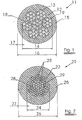
- FIGURE 1 An embodiment of the present invention is provided in FIGURE 1 , being a cable 11 as subject of the invention.
- the cable comprises a steel cord 12, which on its turn comprises several steel filaments 13.
- the present embodiment shows a steel cord "7x7xn" being seven strands 19, each strand having 7 steel elements 13 of diameter of n mm.
- the steel cord has an optical cord diameter 14.
- the steel cord is coated with a polymer material 15, so providing a cable 11 as subject of the invention with an optical cable diameter 16.
- the thickness 17 of the polymer coating is half of the difference between optical cord diameter and optical cable diameter.
- the void space 18 between the different steel elements 13 is substantially filled with polymer material 15.
- FIGURE 2 shows an alternative embodiment of a cable 21 as subject of the invention.
- the cable comprises a steel cord 22, which on its turn comprise several steel filaments 23.
- the present embodiment shows a steel cord 22 being a core strand comprising nineteen steel filaments 23, around which eight strands 29 of each time seven steel filaments 23 are twisted.
- the steel cord has an optical cord diameter 24.
- the steel cord is coated with a polymer material 25, so providing a cable 21 as subject of the invention with an optical cable diameter 26.
- the thickness 27 of the polymer coating is half of the difference between optical cord diameter and optical cable diameter.
- the void space 28 between the different steel elements 23 is substantially filled with polymer material 25.
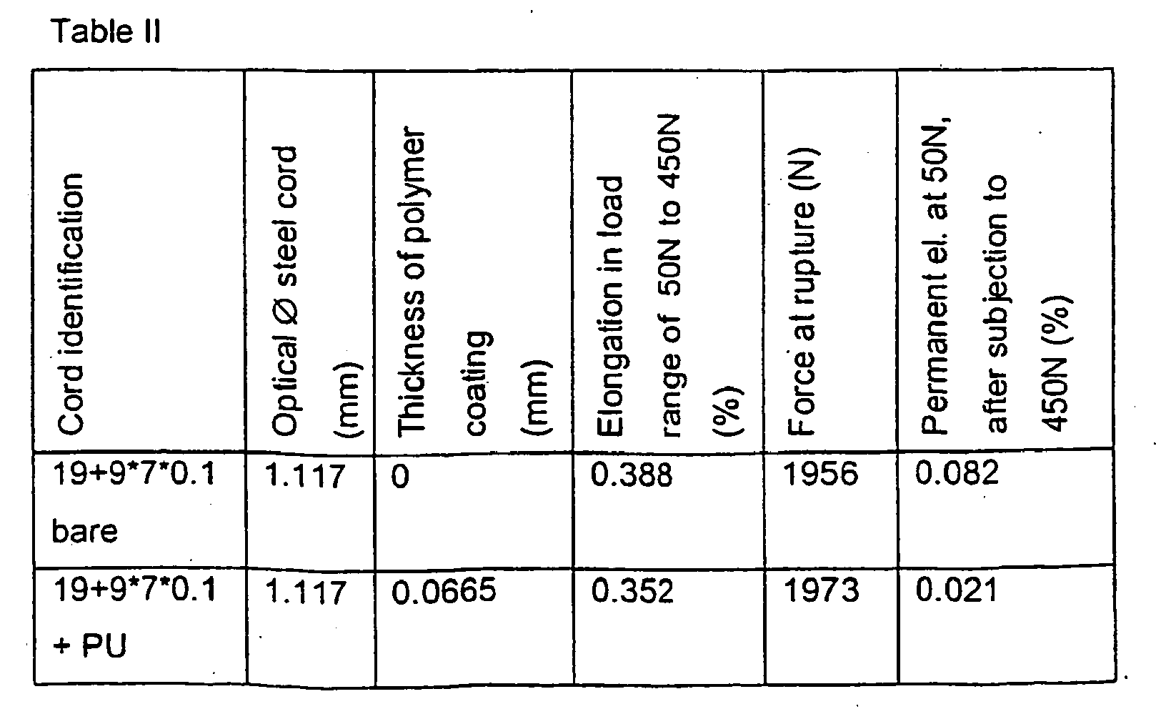
- Test results of an embodiment are given in Table II, in which the embodiment is coded "steel cord + PU".
- the diameter of all steel elements is 0.1 mm. All filaments had a tensile strength of approximately 2800N/mm 2 .
- the polymer used to coat the steel cords to provide a cable as subject of the invention was polyurethane. Identical cables without coating were also tested and the results are incorporated in Table II as well (coded "steel cord bare").
- steel cords all were provided using several steel elements, which have an equal diameter.
- steel cords comprising steel filaments, which have different diameters, may be used.
- the polymer has filled substantially all void space between the steel filaments of the cord, so polymer material is present at the void space radial inwards of the jacket center circle of the cord.
- more than 90% of all void space between the filaments is filled with polymer material, most preferably more than 95% or even more than 99% is filled with polymer material. In the above tested embodiments more than 99% of all void space was filled with PU.
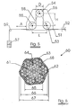
- FIGURE 5 The test is schematically shown in FIGURE 5 .
- a cable 51 is clamped at one end by means of a clamping device 52.
- the cable 51 is bend around three rollers (53, 54 and 55), which are mounted rotationally on a metal piece 56.
- the other end of the cable is loaded with a force by means of a weight 57.
- the three rollers 53, 54 and 55 are mounted on the metal piece 56 in such a way that they are located at the corners of an isosceles triangle 58, which has its hypotenuse parallel with the imaginary connection line between clamping device 52 and bending point 59.
- the lower points of the rollers 53 and 55 are also points of this imaginary connection line between clamping device 52 and bending point 59.
- the rollers 53, 54 and 55 have a diameter D of 20.3mm.
- the length of the hypotenuse (L) is 62.1mm and the height of the triangle (H) is 12.5mm.
- the weight 57 is chosen to provide a force of 150N.
- the cable, mounted on this testing device, is subjected to a fatigue test by moving the metal piece 56 fore and backwards, in the direction of the imaginary connection line between clamping device 52 and bending point 59, over a certain length A, being 90mm. Such movement is done cyclically, with a frequency which is set to 230 movements per minute. In such a way, the cable is cyclically subjected to a bending action. The number of movements is counted before the cable breaks. Results of the tests, done on the cables as described in FIGURE 1 and FIGURE 2 are shown in Table III.
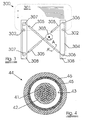
- the cables as subject of the invention may be used in a window elevator system 300 of which an example is shown in FIGURE 3 .
- window elevator system 300 comprises clamping elements 302 which hold the window 301.
- the clamping elements 302 are mounted to the cable 304 as subject of the invention.
- This cable 304 transfers the rotating movement of the rotating device 303 to a lifting (up or down) of the window 301.
- Certain parts of the cable may move (slide)-inside a casing 305.
- guiding parts such as fixed elements 306 or wheels 307 may be used, which are on its turn mounted on a fixing element 308.
- the use of a cable as subject of the invention has several advantages.
- the cable is pretensioned over the guiding elements 306 and 307, since otherwise the cable will run of these guiding element when the cable is used to transfer the rotating movement of the driving drum to a displacement of the glass.
- the level of pretentioning may decrease, since the cable elongates, which on its turn may cause disfunctioning of the whole system.
- FIGURE 4 which is a cut over the plane AA', in case a cable in a casing is used, there is no risk of metal-metal contact between the steel cord 41 of the cable 42 and the metal inner surface 43 of the casing 44, being a metal reinforcing structure 45, coated externally with a polymer layer 46. A polymer inner liner between casing and cable is no longer necessary.
- cables as subject of the invention can be used for control cable applications, static or dynamic applications, e.g. hoisting, timing belts, flat belts or V-belts, cables used in elevator door systems mirror cables, brake cables, hood and trunk release cables.
- the cable 60 has a steel cord comprising a core strand 61 of steel filaments, encompassed with a jacket layer of 6 strands of each 7 steel filaments.
- the cord is substantially identical as the one shown in FIGURE 1 .
- the steel cord is provided with a polymer layer 63 which is this embodiment does not have a circular cross section, but which essentially has the same outer profile as the cord used. Alternatively, other profiles may also be obtained.
- the cable optical diameter is indicated 67, whereas the cord optical diameter is indicated 66.
- the polymer material 63 is present in the void spaces 64 of the cord, radially inwards of the jacked layer circle, indicated 68. Preferably at least 30% of the void space is filled with polymer.
- Most preferred Polyurethane is used as polymer material. Care is taken to obtain a chemical bond between the steel and polymer material.
Landscapes
- Engineering & Computer Science (AREA)
- General Engineering & Computer Science (AREA)
- Health & Medical Sciences (AREA)
- Oral & Maxillofacial Surgery (AREA)
- Mechanical Engineering (AREA)
- Ropes Or Cables (AREA)
- Window Of Vehicle (AREA)
- Lift-Guide Devices, And Elevator Ropes And Cables (AREA)
- Power-Operated Mechanisms For Wings (AREA)
- Insulated Conductors (AREA)
- Lock And Its Accessories (AREA)
- Closing And Opening Devices For Wings, And Checks For Wings (AREA)
Abstract
Description
- The present invention relates to a cable, and the use of such cable in a window elevator system, comprising such cable as part of its transmission member and the use of such cable in control cable applications, static or dynamic applications, e.g. hoisting, timing belts, flat belts or V-belts.
- Window elevator systems as known in the art, comprise a window, clamping parts holding the window, guiding parts (fixed elements or small wheels) over which the cable is bend in order to guide the cable in a defined direction, a driving drum and a transmission member. The transmission member transfers the rotating movement of the driving drum to the window. Usually, a known transmission member comprises a galvanized steel cable, which moves inside a casing. Such casing is usually a steel casing, coated with a polymeric coating. Between the galvanized steel cable and the inner side of the steel casing, a polymer inner liner is placed, being a polymer tube, fitting closely with the inner side of the steel casing.
- Galvanized steel cables, being part of such transmission member, have to meet several requirements, such as a high corrosion resistance (simulated by means of the so-called "salt spray test"), a temperature stability in the temperature range from -40°C up to 90°C or even up to higher temperatures for a short period of time, high tensile strength and a good fatigue resistance. Requirements which are to be met in order to provide systems which function during the whole life-time of the vehicle.
- Further, the weight of the steel cord, and of the transmission member as a whole, is to be as low as possible. The cable of the transmission member is to be bend in curvatures having decreasing bending radii. Such curvatures are found at the guiding parts of the window elevator system, over which the cable is to be bend. These decreasing bending radii require cables with increased flexibility and fatigue resistance. Finally, the cable has to have a minimum of permanent elongation, after being subjected to an elongating force. Too much permanent elongation leads to incorrect closing and opening of the windows, and a cable which runs off the guiding parts of the system, since the cable looses its tensioning around these guiding parts.
- Several attempts have been made to provide a solution to all above-mentioned problems simultaneously, however with little result.
- Cables used for control cable applications or other static or dynamic applications have to have also limited permanent elongation and are subjected to similar if not identical requirements.
- Also in other applications, relatively small cables have to have a very limited permanent elongation. E.g. cables used to open and close breaks of scooters, bicycles and other vehicles, preferably have no or very small permanent elongation. If the permanent elongation is too large, inadequate displacement of the connected elements of the breaks may occur.
- Strands made of steel wires with an outer diameter of between 0.80 to 2.50 mm that are externally coated with an extruded material selected from the group consisting of polyethylene terephtalate, polybutylene terephtalate, and polyethylene naphtenate have been described in
EP 0864688 A1 . However, nothing is learned in this application in order to lower the permanent elongation of these strands in order to make them suitable for the applications indicated above. - Strands made of steel wires that are covered with an extruded sheath of polymeric material and are lubricated after application of the coating are described in
GB 1563712 - According to the present invention, a cable is provided comprising a polymer coated steel cord, said cable having a permanent elongation of less than 0.05% at a permanent force of 50N, after being subjected to a force of 450N. Cables, as subject of the invention comprises a steel cord, which has an optical diameter of less than 2.5mm. The optical diameter is the diameter of the smallest imaginary circle, which encircles a radial cross section of the steel cord.
- The polymer material and the degree of penetration of the polymer material between the steel elements of the cable, the thickness of the coating and the construction of the steel cord may be chosen in such a way that the cables meet the required properties in an optimal way.
- Cables, as subject of the invention comprise a steel cord, which preferably has a relatively small optical diameter. The optical diameter of the cord is preferably less than 2.5mm, more preferred less than 2.3mm or even less than 2mm, most preferably less than 1.85mm or even less than 1.55mm. The optical diameter is the diameter of the smallest imaginary circle, which encircles a radial cross section of the steel cord.
- The steel cord usually has a breaking load of less than 3150 N.
- A cable as subject of the invention has a very limited permanent elongation at a load of 50N after being loaded with a load of 450N. Possibly, a permanent elongation may be obtained of less than 0.05%, even less than 0.04%, preferably however less than 0.03% or even less than 0.02%. Identical if not similar permanent elongation may even be obtained when the cable is subjected to a load causing tensile strengths in the cord in the range up to 390 N/mm2, or even up to 580 N/mm2, or even up to levels of 820 N/mm2 or 1185 N/mm2. The tensile strengths are calculated using the steel surface in the radial cross-section of the cable.
- A cable as subject of the invention comprises a steel cord, which on its turn comprises several steel filaments.
- The tensile strength of the steel filaments are preferably more than 1700 N/mm2, or more than 2000 N/mm2 or even more 2600 N/mm2, most preferably more than 3000 N/mm2 or even more than 4000 N/mm2. The diameter of the filaments is less than 210µm, preferably less than 160µm, most preferably less than 110µm.
- All filaments may have an identical diameter. Possible the diameter of the filaments may differ from each other. Preferably, the diameter of the filaments, providing an inner strand of the cable is larger than the diameter of the filaments, used to provide the outer strands or layer of filaments to the cable, which improves the penetration of the polymer material into the void spaces of the cable.
- A steel cord, used to provide a cable as subject of the invention, comprises several steel elements, being transformed into a steel cord, using a steel cord construction. Due to the steel cord construction, void spaces are provided between the steel filaments of the steel elements of the cord. Also void spaces are provided between the steel elements. "Void space" as used hereafter is to be understood as all area of a radial cross-section of the cord, located inwards of the imaginary circle having as diameter the optical diameter of the cord, which area is not occupied by steel.
- Steel cords have an inner layer or core, which is preferably a strand of several steel filaments. Around such core, at least one layer of additional steel elements is provided. The steel elements of the additional layer can either be steel filaments or steel strands, on its turn comprising steel filaments. The outer layer of steel elements (either filaments or strands) is hereafter referred to as "jacket layer". The" jacket center circle" as used hereafter, is the imaginary circle connecting the centers of the steel elements of the jacket layer. Various steel cord constructions may be used:
- Examples here are:
- multi-strand steel cords e.g. of the m x n type, i.e. steel cords, comprising m strands with each n wires, such as 4x7x0.10, 7x7x0.18, 8x7x0.18 or 3x3x0.18 ; the last number is the diameter of the wire, expressed in mm.
- Multi-strand steel cords, comprising a core stand of I metal filaments, and n strands of m metal filaments, surrounding the core strand. These steel cords are hereafter referred to as I+nxm type cords, such as 19+9x7 or 19+8x7 cords;
- Warrington-type steel cords;
- compact cords, e.g. of the 1 x n type, i.e. steel cords comprising n steel wires, n being greater than 8, twisted in only one direction with one single step to a compact cross-section, such as 1x9x0.18 ; the last number is the diameter of the wire, expressed in mm.
- layered steel cords e.g. of the l + m (+ n) type, i.e. steel cords with a core of I wires, surrounded by a layer of m wires, and possibly also surrounded by another layer of n wires , such as 2+4x0.18; the last number is the diameter of the wire, expressed in mm.
- The steel composition is preferably a plain carbon steel composition, i.e. it generally comprises a minimum carbon content of 0.40 % (e.g. at least 0.60 % or at least 0.80 %, with a maximum of 1.1 %), a manganese content ranging from 0.10 to 0.90 % and a silicon content ranging from 0.10 to 0.90 % ; the sulfur and phosphorous contents are each preferably kept below 0.03 % ; additional micro-alloying elements such as chromium (up to 0.2 à 0.4 %), boron, cobalt, nickel, vanadium ... may be added to the composition; stainless steel compositions are, however, not excluded.
- Such steel cords, without a polymer coating, usually have a permanent elongation at a load of 50N, after being subjected to an elongation load of 450N, which is substantially more than 0.05%. The more complex the cord construction is, the larger the difference in permanent elongation becomes between a cable being such bare cord and a cable as subject of the invention using such cord.
- Preferably, the polymer material is applied is such a way that at least a part of the void space, present radial inwards of the jacket center circle, is filled with polymer material. Most preferred, at least 10% or even more than 15% of the void space radial inwards of the jacket center circle is filled with polymer.
- Preferably, a polymer material is provided around the steel cord in such a way that the void spaces are filled for more than 30%, or even for more than 40% or 50%.
- Even more preferred, polymer material is provided around the steel cord in such a way that the void spaces between adjacent steel elements are substantially filled with polymer material. Preferably more than 90%, most preferably even more than 95% or more than 99% of all void space is filled with polymer material. The coating may be provided using different techniques such as extrusion, lamination or dipping. Preferably, the coating is provided via extrusion.
- Best results as far as the limitation of the permanent elongation as subject of the invention are obtained, when thermoplastic elastomers (TPE) are used, such as styrene polymers (TES), polyurethane (PU) or polyurethane copolymers, polyetheresters (TEEE), polyetheramide (PEBA), thermoplastic vulcanizates or silicone. Preferably, thermoplastic polyurethane is used. Homopolymers of ester, ether or carbonate polyurethane may be used, as well as copolymers or polymer blends. Possibly however, polytetrafluorethylene (PTFE) may be used. Preferably, the polymer material has a shore D hardness varying between 60 and 100, preferably between 85 and 95. Alternatively, thermoset polymers may be used.
- Possibly, plasticizers or other additives may be added to the polymer material, to improve its behaviors, such as e.g. lowering its friction coefficient, to improve the UV-resistance of the polymer material; to reduce the humidity absorption properties of the polymer material or to improve the temperature stability in a larger temperature range of the polymer material.
- A preferred cable as subject of the invention has a polymer material which is chemically anchored to the steel using appropriate coatings. Reference for possible coatings is made to
WO0023505 - The thickness of the polymer material, being defined as the half of the difference of the optical diameter between the coated and non-coated steel cord, is preferably less than 250µm, most preferably less than 200µm or even less than 100µm.
- A cable as subject of the invention preferably is provided in such a way that a radial cross section of such cable has a substantially circular shape. Alternatively, a radial cross-section of the cable has an outer profile, which is substantially similar to the profile of a radial cross-section of the cord.
- The diameter of the smallest circle encompassing this radial cross section of the cable, being the optical diameter of the cable, is preferably less than 3 mm, most preferably less than 2.75mm, or even smaller than 1.6 mm.
- A cable as subject of the invention has several advantages over the present prior art.
- A cable as subject of the invention has a very good resistance to corrosion. Subjected to a salt spray test (ISO9227), such cables do not show any corrosion after 600 hours. It was found that the conventional coatings, such as Zn-coatings which are applied to the steel cables used in prior art, or the use of grease with corrosion protective additives to improve the corrosion resistance, are no longer necessary to obtain acceptable levels of corrosion resistance. Notwithstanding this, the steel cords used to provide a cable as subject of the invention, may have a coating such as yellow brass coatings, electrolytic galvanized coating or hot dip galvanized coating to improve the processability of the steel elements, steel strands and/or steel cord and to improve the polymer coating process, e.g. the extrusion process.
- At a load of 450N, a cable as subject of the invention shows a limited level of creep, being typically less than 0.005%. The elongation of the cable when being subjected to a load of 450N is usually less than 0.6%, preferably less than 0.5% or even less than 0.4 % or 0.3%.
- Also the fatigue resistance is improved, and its flexibility is significantly improved. This is clear from the "three-roller" test, where the products have a fatigue cycle of at least 2 times more, or even up to 5 or 10 times more as compared with a life time of identical uncoated cables. Fatigue life cycles of more than 8000 cycles, but usually and preferably more than 9000 or even more than 15000 and more than 20000 cycles are obtained
- The temperature resistance is also improved. The polymer coating, especially when a polyurethane coating is used, does not show a degradation of properties in the range of -40°C to 90°C, and resists exposures of at least one hour to temperatures above 90°C. Conventional cables known in the prior art, may loose their oil or grease due to the elevated temperatures, which result in higher corrosion or a decrease of friction properties. Since there is no oil or grease needed, hardening of the cable due to hardening of the oil or grease does not occur. The problem of oil or grease, attracting dust and small particles such as sand particles, and causing excessive wear of parts and causing noise, is avoided.
- A cable as subject of the invention further doesn't flare when cut into pieces to be used in the appropriate application. This allows easier mounting of the cable in the different systems, e.g. window elevator systems.
- A cable as subject of the invention may be used for several purposes, such as window elevator systems, sunroof opening systems, cables to move sliding doors, seat adjustment systems, seat release cables, brake cable for vehicles such as bicycles, scooters such as jet- or snowscooters, derailleur or shift lever cables for vehicles such as bicycles, jetskis, waterskis or scooters, cable for directing mirrors in vehicles, cables for adjusting or commanding gear systems of bicycles or other vehicles and cables used to start small combustion engines. Cable as subject of the invention may also be used for control cable applications, static or dynamic applications, e.g. hoisting, timing belts, flat belts or V-belts.
- Especially the corrosion resistance properties and the temperature stability of the cables as subject of the invention provide a benefit over the known prior art. Further, since the cables provide a good flexibility and higher fatigue resistance, the cables can be bent over smaller guiding pieces in he transmission system in which it is used. Also the use of a polymer liner inside a casing, which is to be used when using ordinary, non-coated cords, can be omitted. This results in less weight and a more simple construction of the transmission systems in which the cable as subject of the invention is used.
- Especially, a window elevator system comprising a cable as subject of the invention is provided according to the present invention.
- A window elevator system as subject of the invention comprises a clamping system for holding a window, a rotating device (e.g. a motor or a manual rotating device), a cable as subject of the invention and at least one guiding part, over which the cable is bend. The cable may slide partially in a casing.
- A window elevator system as subject of the invention has several advantages due to the use of a cable as subject of the invention.
- The window elevator system provides a stable and reliable movement of the window. This is due to the low elongation at 50N after being loaded to a level of 450N.
- The window elevator system is simplified and does not have to comprise as much elements as in prior art. An inner liner between casing and cable is not necessary, and the guiding part or parts may be reduced in size, having smaller bending radii.
- Further the use of oil and/or grease may be reduced or avoided, meanwhile obtaining a very good resistance to corrosion.
- The invention will now be described into more detail with reference to the accompanying drawings wherein
-
FIGURE 1 is a schematic view of a cable as subject of the invention -
FIGURE 2 is a schematic view of an other cable as subject of the invention; -
FIGURE 3 is a schematic view of a window elevator system as subject of the invention -
FIGURE 4 is a schematic view of a radial cut of a cable as subject of the invention sliding in a casing. -
FIGURE 5 is a schematic view of the three-roller-test. -
FIGURE 6 shows schematically an other cable as subject of the invention. - An embodiment of the present invention is provided in
FIGURE 1 , being acable 11 as subject of the invention. The cable comprises asteel cord 12, which on its turn comprisesseveral steel filaments 13. The present embodiment shows a steel cord "7x7xn" being sevenstrands 19, each strand having 7steel elements 13 of diameter of n mm. - The steel cord has an
optical cord diameter 14. The steel cord is coated with apolymer material 15, so providing acable 11 as subject of the invention with anoptical cable diameter 16. Thethickness 17 of the polymer coating is half of the difference between optical cord diameter and optical cable diameter. As shown inFIGURE 1 , preferably thevoid space 18 between thedifferent steel elements 13 is substantially filled withpolymer material 15. - Several embodiments where tested, as given in Table I. Such cable embodiments are coded as "7x7xn+PU". Identical cables without coating are were also tested and the results are incorporated in Table I as well (coded 7x7xn bare). All filaments had a tensile strength of approximately 2800N/mm2. The polymer used to coat the steel cords to provide a cable as subject of the invention was polyurethane.

-
FIGURE 2 shows an alternative embodiment of acable 21 as subject of the invention. - The cable comprises a
steel cord 22, which on its turn compriseseveral steel filaments 23. The present embodiment shows asteel cord 22 being a core strand comprising nineteensteel filaments 23, around which eightstrands 29 of each time sevensteel filaments 23 are twisted. The steel cord has anoptical cord diameter 24. The steel cord is coated with apolymer material 25, so providing acable 21 as subject of the invention with anoptical cable diameter 26. Thethickness 27 of the polymer coating is half of the difference between optical cord diameter and optical cable diameter. As shown inFIGURE 2 , preferably thevoid space 28 between thedifferent steel elements 23 is substantially filled withpolymer material 25. - Test results of an embodiment are given in Table II, in which the embodiment is coded "steel cord + PU". The diameter of all steel elements is 0.1 mm. All filaments had a tensile strength of approximately 2800N/mm2. The polymer used to coat the steel cords to provide a cable as subject of the invention was polyurethane. Identical cables without coating were also tested and the results are incorporated in Table II as well (coded "steel cord bare").
- The above mentioned and described steel cords all were provided using several steel elements, which have an equal diameter. To further improve the degree of filling the void spaces between the elements, steel cords comprising steel filaments, which have different diameters, may be used.
- During coating of the steel cord, care was taken that the polymer has filled substantially all void space between the steel filaments of the cord, so polymer material is present at the void space radial inwards of the jacket center circle of the cord. Preferably more than 30% of all void space between the filaments is filled with polymer material. Even more preferred, more than 90% of all void space between the filaments is filled with polymer material, most preferably more than 95% or even more than 99% is filled with polymer material. In the above tested embodiments more than 99% of all void space was filled with PU.
- All above given embodiments were subjected to a corrosion test according to ISO9227. After 600h, no indication of corrosion was noticed.
- All above given embodiments were subjected to a fatigue test, so called "three roller test". This test provides data, giving significant information on the flexibility of the cable and the resistance to periodical bending loads.
- The test is schematically shown in
FIGURE 5 . Acable 51 is clamped at one end by means of aclamping device 52. Thecable 51 is bend around three rollers (53, 54 and 55), which are mounted rotationally on ametal piece 56. The other end of the cable is loaded with a force by means of aweight 57. The threerollers metal piece 56 in such a way that they are located at the corners of an isosceles triangle 58, which has its hypotenuse parallel with the imaginary connection line between clampingdevice 52 and bendingpoint 59. The lower points of therollers device 52 and bendingpoint 59. - The
rollers weight 57 is chosen to provide a force of 150N. - The cable, mounted on this testing device, is subjected to a fatigue test by moving the
metal piece 56 fore and backwards, in the direction of the imaginary connection line between clampingdevice 52 and bendingpoint 59, over a certain length A, being 90mm. Such movement is done cyclically, with a frequency which is set to 230 movements per minute. In such a way, the cable is cyclically subjected to a bending action. The number of movements is counted before the cable breaks. Results of the tests, done on the cables as described inFIGURE 1 and FIGURE 2 are shown in Table III.TABLE III sample Cycles up to breaking bare PU 7x7x0.12 bare 1499 8724 7x7x0.12 bare 693 10731 7x7x0.10 bare 1168 18062 19+9*7*0.1 bare 2885 24338 - The cables as subject of the invention may be used in a
window elevator system 300 of which an example is shown inFIGURE 3 . Suchwindow elevator system 300 comprises clampingelements 302 which hold thewindow 301. The clampingelements 302 are mounted to thecable 304 as subject of the invention. Thiscable 304 transfers the rotating movement of therotating device 303 to a lifting (up or down) of thewindow 301. Certain parts of the cable may move (slide)-inside acasing 305. Where the cable is to be bend over a curve with relatively short bending radius, guiding parts such asfixed elements 306 orwheels 307 may be used, which are on its turn mounted on a fixingelement 308. - The use of a cable as subject of the invention has several advantages. The cable is pretensioned over the guiding
elements FIGURE 4 , which is a cut over the plane AA', in case a cable in a casing is used, there is no risk of metal-metal contact between thesteel cord 41 of thecable 42 and the metalinner surface 43 of thecasing 44, being ametal reinforcing structure 45, coated externally with apolymer layer 46. A polymer inner liner between casing and cable is no longer necessary. - This also is applicable when the cable as subject of the invention is used for other purposes, in which a cable is to move inside a casing, such as for the closing of the breaks in scooters and bicycles. The same cables as subject of the invention can be used for control cable applications, static or dynamic applications, e.g. hoisting, timing belts, flat belts or V-belts, cables used in elevator door systems mirror cables, brake cables, hood and trunk release cables.
- An other cable as subject of the invention is shown in
FIGURE 6 . Thecable 60 has a steel cord comprising acore strand 61 of steel filaments, encompassed with a jacket layer of 6 strands of each 7 steel filaments. The cord is substantially identical as the one shown inFIGURE 1 . The steel cord is provided with apolymer layer 63 which is this embodiment does not have a circular cross section, but which essentially has the same outer profile as the cord used. Alternatively, other profiles may also be obtained. The cable optical diameter is indicated 67, whereas the cord optical diameter is indicated 66. It is dearly shown that thepolymer material 63 is present in thevoid spaces 64 of the cord, radially inwards of the jacked layer circle, indicated 68. Preferably at least 30% of the void space is filled with polymer. Most preferred Polyurethane is used as polymer material. Care is taken to obtain a chemical bond between the steel and polymer material.
Claims (15)
- <amended> A cable (11,21,60) comprising a steel cord (12, 22) and a polymer material (15,25,63), said steel cord comprising a core (18,28,61) surrounded by a jacket layer of steel elements (19,29) the centers of which are situated on a jacket center circle (68), said steel cord having an optical diameter (14,24,66) less than 2.5mm, said steel cord being coated with said polymer material characterized in that at least part of said polymer material has radially entered said jacket center circle thereby reducing the permanent elongation of said cable to less than 0.05% at a permanent force of 50N, after being subjected to a force of 450N.
- <amended> The cable as in claim 1, wherein said steel elements are steel strands (19,29) comprising steel filaments (13,23).
- The cable (60) as in any one of claim 1 to 2. said steel cord comprising at least two steel elements, said steel cord having void space (64) between said steel elements, said polymer material, (63) filling more than 30% of said void space.
- The cable as in any one of claim 1 to 3, said polymer material being chemically anchored to said steel cord.
- The cable as in any on of claim 1 to 4, said cable having an optical diameter of less than 3mm.
- The cable as in any on of claim 1 to 5, said steel cord having a breaking load of less than 3150N
- The cable as in any on of claim 1 to 6, said cord having an optical diameter of less than 2.75mm.
- The cable as in any on of claim 1 to 7, said polymer being a thermoplastic elastomer.
- The cable as in claim 8, said thermoplastic elastomer being polyurethane.
- The cable as in any on of claim 1 to 7, said polymer being a thermoset polymer.
- The cable as in any on of claim 1 to 10, said cable having a substantially circular radial cross section.
- The cable as in any one of claim 1 to 11, said cable having an elongation of less than 0.6% when being subjected to a force of 450N.
- <amended> Use of a cable as in any one of claim 1 to 12 in a window elevator system or in control cable applications, or in timing belts or in hoisting belts, or in flat belts or in V-belts or in static or dynamic applications.
- <amended> A window elevator system (300) comprising a clamping system (302), a rotating device (303), at least one guiding part (306,307) and a cable (304), said cable being bent around said guiding parts, characterized in that said cable (304) has all of claim 1.
- The window elevator system as in claim 14, said window elevator system further comprising a casing (305).
Priority Applications (2)
| Application Number | Priority Date | Filing Date | Title |
|---|---|---|---|
| EP02798317A EP1454007B1 (en) | 2001-11-23 | 2002-11-22 | Cable and window elevator system using such cable |
| ES02798317T ES2305343T3 (en) | 2001-11-23 | 2002-11-22 | CABLE AND WINDOW LIFTING SYSTEM THAT USES SUCH CABLE. |
Applications Claiming Priority (4)
| Application Number | Priority Date | Filing Date | Title |
|---|---|---|---|
| EP01204515 | 2001-11-23 | ||
| EP01204515A EP1314813A1 (en) | 2001-11-23 | 2001-11-23 | Cable and window elevator system using such cable |
| EP02798317A EP1454007B1 (en) | 2001-11-23 | 2002-11-22 | Cable and window elevator system using such cable |
| PCT/EP2002/013182 WO2003044267A1 (en) | 2001-11-23 | 2002-11-22 | Cable and window elevator system using such cable |
Publications (2)
| Publication Number | Publication Date |
|---|---|
| EP1454007A1 EP1454007A1 (en) | 2004-09-08 |
| EP1454007B1 true EP1454007B1 (en) | 2008-04-30 |
Family
ID=8181287
Family Applications (2)
| Application Number | Title | Priority Date | Filing Date |
|---|---|---|---|
| EP01204515A Withdrawn EP1314813A1 (en) | 2001-11-23 | 2001-11-23 | Cable and window elevator system using such cable |
| EP02798317A Expired - Lifetime EP1454007B1 (en) | 2001-11-23 | 2002-11-22 | Cable and window elevator system using such cable |
Family Applications Before (1)
| Application Number | Title | Priority Date | Filing Date |
|---|---|---|---|
| EP01204515A Withdrawn EP1314813A1 (en) | 2001-11-23 | 2001-11-23 | Cable and window elevator system using such cable |
Country Status (14)
| Country | Link |
|---|---|
| US (1) | US7770328B2 (en) |
| EP (2) | EP1314813A1 (en) |
| JP (1) | JP2005509762A (en) |
| KR (1) | KR100959840B1 (en) |
| CN (1) | CN100396845C (en) |
| AT (1) | ATE393854T1 (en) |
| AU (1) | AU2002363858A1 (en) |
| BR (1) | BR0214379B1 (en) |
| CA (1) | CA2466623A1 (en) |
| DE (1) | DE60226339T2 (en) |
| ES (1) | ES2305343T3 (en) |
| MX (1) | MXPA04004910A (en) |
| PL (1) | PL198447B1 (en) |
| WO (1) | WO2003044267A1 (en) |
Families Citing this family (36)
| Publication number | Priority date | Publication date | Assignee | Title |
|---|---|---|---|---|
| CA2445436C (en) | 2001-04-26 | 2009-06-09 | Intier Automotive Closures Inc. | Universal cable window regulator assembly for vehicles |
| DE50306853D1 (en) * | 2003-07-16 | 2007-05-03 | Brugg Drahtseil Ag | Running longitudinal element, in particular an elevator, a crane longitudinal element or the like |
| US20060053945A1 (en) * | 2004-07-13 | 2006-03-16 | Markel Corporation | Cable assemblies with sound abatement layer |
| DE102004061385B4 (en) * | 2004-12-21 | 2007-11-29 | W.H. Küster GmbH & Co KG | Pulling rope with plastic filling and plastic outer sheath |
| CN101243225B (en) * | 2005-08-19 | 2011-08-10 | 贝卡尔特股份有限公司 | A polymer impregnated steel cord and impregnation method thereof |
| PT2365108T (en) | 2005-12-21 | 2018-07-05 | Bekaert Advanced Cords Aalter Nv | A steel wire rope for use in a drive system |
| EP1942224A1 (en) * | 2007-01-08 | 2008-07-09 | NV Bekaert SA | Cable with low structural elongation |
| US20090226177A1 (en) * | 2007-01-26 | 2009-09-10 | Woosnam Calvin H | Communications Cable and Method of Making Same |
| US20080211730A1 (en) | 2007-01-26 | 2008-09-04 | Woosnam Calvin H | Gimbaled Mount System for Satellites |
| JP2009167545A (en) * | 2008-01-11 | 2009-07-30 | Toshiba Elevator Co Ltd | Wire rope |
| DE102008037537B4 (en) * | 2008-11-10 | 2020-11-05 | Contitech Antriebssysteme Gmbh | Traction drive and elevator system with this traction drive |
| DE102008037538A1 (en) * | 2008-11-10 | 2010-05-12 | Contitech Antriebssysteme Gmbh | Traction system for an elevator installation |
| DE102008037536A1 (en) * | 2008-11-10 | 2010-05-12 | Contitech Antriebssysteme Gmbh | Traction means, traction drive with this traction device and elevator system |
| US8402731B2 (en) * | 2008-12-17 | 2013-03-26 | Mitsubishi Electric Corporation | Elevator rope |
| DE102009041706A1 (en) * | 2009-09-16 | 2011-03-24 | GM Global Technology Operations, Inc., Detroit | Connection device for a control cable and transmission of a motor vehicle with this attachment device |
| FR2962455B1 (en) * | 2010-05-20 | 2012-09-21 | Soc Tech Michelin | MULTILAYER METALLIC CABLE GUM IN SITU BY UNSATURATED THERMOPLASTIC ELASTOMER |
| JP5269838B2 (en) * | 2010-07-12 | 2013-08-21 | 株式会社日立製作所 | Elevator wire rope |
| US20130130030A1 (en) * | 2010-09-09 | 2013-05-23 | Mitsubishi Electric Corporation | Elevator rope |
| BR112013023749A2 (en) | 2011-04-14 | 2016-12-13 | Otis Elevator Co | rope or belt, and rope used on a sheathed rope or belt to suspend and / or drive an elevator car, and method of forming a rope or belt |
| US20120291356A1 (en) * | 2011-05-17 | 2012-11-22 | First Dome Corporation | Synchronous drive device for slide cover mechanism |
| US20130081508A1 (en) | 2011-09-29 | 2013-04-04 | Shimano Inc. | Bicycle control cable |
| ES2594003T3 (en) * | 2011-10-13 | 2016-12-15 | Bekaert Advanced Cords Aalter Nv | A load assembly comprising a steel cable and a liner |
| CN102359543A (en) * | 2011-10-20 | 2012-02-22 | 无锡通用钢绳有限公司 | Flat steel strip for elevator |
| CN103088682A (en) * | 2011-10-28 | 2013-05-08 | 常州瑞通新型线材有限公司 | Plastic-covered steel wire |
| US20150099068A1 (en) | 2011-11-28 | 2015-04-09 | Nv Bekaert Sa | Steel cord for extrusion process, an apparatus and method and use of said steel cord |
| RU2617031C2 (en) | 2012-04-24 | 2017-04-19 | ДСМ АйПи АССЕТС Б.В. | Combo cable or combination locks |
| MY169899A (en) * | 2012-10-05 | 2019-06-12 | Dsm Ip Assets Bv | Hybrid rope |
| KR102206177B1 (en) | 2014-07-01 | 2021-01-22 | 엘지전자 주식회사 | Compressor and assembly method thereof |
| DE102015222272A1 (en) * | 2015-11-12 | 2017-05-18 | Contitech Transportbandsysteme Gmbh | Method for producing a tension member and tension members |
| US11485611B2 (en) * | 2016-07-19 | 2022-11-01 | Bekaert Advanced Cords Aalter Nv | Elevator tension member with a hard thermoplastic polyurethane elastomer jacket |
| US11066783B2 (en) * | 2018-09-17 | 2021-07-20 | Leggett & Platt Canada Co. | Corrosion resistant cable |
| CN109853278B (en) * | 2019-04-16 | 2024-01-30 | 中国科学院海洋研究所 | Rope capable of preventing organisms from adhering |
| FR3103501B1 (en) * | 2019-11-22 | 2021-10-29 | Reel | HYBRID LIFTING CABLE, PROCESS FOR ITS REALIZATION AND CAPSTAN WINCH IMPLEMENTING SUCH A CABLE |
| CN118202111A (en) * | 2021-11-08 | 2024-06-14 | 通力股份公司 | Ropes and Hoists |
| US12208992B1 (en) * | 2023-10-23 | 2025-01-28 | Otis Elevator Company | Elevator suspension member with coating |
| US20260109576A1 (en) * | 2024-10-23 | 2026-04-23 | Otis Elevator Company | Elevator belt with steel cord |
Family Cites Families (20)
| Publication number | Priority date | Publication date | Assignee | Title |
|---|---|---|---|---|
| DE1904468A1 (en) * | 1969-01-30 | 1970-08-27 | Berkenhoff & Drebes Ag | Bonding a plastic casing to a wire cable |
| US3634607A (en) * | 1970-06-18 | 1972-01-11 | Coleman Cable & Wire Co | Armored cable |
| US3800522A (en) * | 1971-03-30 | 1974-04-02 | Bethlehem Steel Corp | Sealed wire rope and strand and method of making |
| GB1563712A (en) * | 1977-11-02 | 1980-03-26 | Bowden Controls Ltd | Wire cables |
| US4344278A (en) * | 1980-05-30 | 1982-08-17 | Projected Lubricants, Inc. | Lubricated wire rope |
| US4522464A (en) * | 1982-08-17 | 1985-06-11 | Chevron Research Company | Armored cable containing a hermetically sealed tube incorporating an optical fiber |
| US4523804A (en) * | 1982-08-17 | 1985-06-18 | Chevron Research Company | Armored optical fiber cable |
| DE3344985A1 (en) * | 1983-12-13 | 1985-06-20 | August Rich. Dietz & Sohn Draht- u.Hanfseilwerk, 8632 Neustadt | Wire rope having a plastic sheathing |
| US4606183A (en) * | 1984-11-20 | 1986-08-19 | Amsted Industries Incorporated | Lubricated and thermoplastic impregnated wire rope |
| US4829760A (en) * | 1987-05-04 | 1989-05-16 | N.B. Bekaert S.A. | Compact steel cord structure |
| KR100265244B1 (en) * | 1989-07-21 | 2000-09-15 | 가브리엘 데미스터 | Reinforcing substrates and their products |
| US5329605A (en) * | 1992-10-27 | 1994-07-12 | At&T Bell Laboratories | Undersea armored cable |
| EP0864688A1 (en) * | 1997-03-13 | 1998-09-16 | N.V. Bekaert S.A. | Push-pull cable with polymer coating |
| FR2783585B1 (en) * | 1998-09-23 | 2000-11-17 | Trefileurope | MIXED CABLE WITH SYNTHETIC CORE FOR LIFTING OR PULLING |
| AU4136399A (en) | 1998-10-15 | 2000-05-08 | Continental Aktiengesellschaft | Composite of a vulcanizable rubber composition and cured rubber product |
| US6151833A (en) * | 1999-02-26 | 2000-11-28 | Delphi Technologies, Inc. | Extruded guide for automotive window regulator assembly |
| FR2817566B1 (en) * | 2000-12-04 | 2003-02-07 | Freyssinet Int Stup | INDIVIDUALLY PROTECTED CORD, USE THEREOF IN CONSTRUCTION, AND MANUFACTURING METHOD |
| WO2002054131A1 (en) * | 2000-12-28 | 2002-07-11 | Pirelli S.P.A. | Submarine optical cable with water-blocking filling composition |
| FR2824849B1 (en) * | 2001-05-17 | 2005-06-10 | Trefileurope | DYNAMIC CABLE HAVING IMPROVED PROPERTIES, AND METHOD AND INSTALLATION FOR MANUFACTURING SUCH A CABLE |
| US20060174606A1 (en) * | 2005-02-10 | 2006-08-10 | Stram Michael A | High static thrust valveless pulse-jet engine with forward-facing intake duct |
-
2001
- 2001-11-23 EP EP01204515A patent/EP1314813A1/en not_active Withdrawn
-
2002
- 2002-11-22 DE DE60226339T patent/DE60226339T2/en not_active Expired - Lifetime
- 2002-11-22 JP JP2003545877A patent/JP2005509762A/en active Pending
- 2002-11-22 AT AT02798317T patent/ATE393854T1/en not_active IP Right Cessation
- 2002-11-22 MX MXPA04004910A patent/MXPA04004910A/en active IP Right Grant
- 2002-11-22 CA CA002466623A patent/CA2466623A1/en not_active Abandoned
- 2002-11-22 CN CNB028232119A patent/CN100396845C/en not_active Expired - Lifetime
- 2002-11-22 US US10/496,457 patent/US7770328B2/en not_active Expired - Fee Related
- 2002-11-22 ES ES02798317T patent/ES2305343T3/en not_active Expired - Lifetime
- 2002-11-22 AU AU2002363858A patent/AU2002363858A1/en not_active Abandoned
- 2002-11-22 KR KR1020047007790A patent/KR100959840B1/en not_active Expired - Fee Related
- 2002-11-22 BR BRPI0214379-8A patent/BR0214379B1/en not_active IP Right Cessation
- 2002-11-22 PL PL369928A patent/PL198447B1/en unknown
- 2002-11-22 WO PCT/EP2002/013182 patent/WO2003044267A1/en not_active Ceased
- 2002-11-22 EP EP02798317A patent/EP1454007B1/en not_active Expired - Lifetime
Also Published As
| Publication number | Publication date |
|---|---|
| KR100959840B1 (en) | 2010-05-28 |
| PL198447B1 (en) | 2008-06-30 |
| US7770328B2 (en) | 2010-08-10 |
| CA2466623A1 (en) | 2003-05-30 |
| PL369928A1 (en) | 2005-05-02 |
| BR0214379B1 (en) | 2012-11-27 |
| AU2002363858A1 (en) | 2003-06-10 |
| ES2305343T3 (en) | 2008-11-01 |
| JP2005509762A (en) | 2005-04-14 |
| KR20040062639A (en) | 2004-07-07 |
| US20050034375A1 (en) | 2005-02-17 |
| DE60226339D1 (en) | 2008-06-12 |
| CN100396845C (en) | 2008-06-25 |
| MXPA04004910A (en) | 2004-07-30 |
| WO2003044267A1 (en) | 2003-05-30 |
| DE60226339T2 (en) | 2009-06-10 |
| EP1454007A1 (en) | 2004-09-08 |
| EP1314813A1 (en) | 2003-05-28 |
| ATE393854T1 (en) | 2008-05-15 |
| CN1589347A (en) | 2005-03-02 |
| BR0214379A (en) | 2004-11-03 |
Similar Documents
| Publication | Publication Date | Title |
|---|---|---|
| US7770328B2 (en) | Cable and window elevator system using such cable | |
| KR101095474B1 (en) | Elevator rope | |
| US7757472B2 (en) | Synthetic fiber cable and elevator installation with such a synthetic fiber cable | |
| EP2104764B1 (en) | Cable with low structural elongation | |
| JP2014535009A (en) | Load bearing assembly with steel rope and jacket | |
| KR20090117743A (en) | Steel cord with iron-zinc alloy coating | |
| CN101528583A (en) | Drive and suspension element for elevator apparatuses and elevator apparatus | |
| EP0896087A1 (en) | A wire rope having an independent wire rope core | |
| WO2009080583A1 (en) | A steel cord comprising a heat-curable one-component thermosetting material | |
| JP3827610B2 (en) | Multilayer twisted wire rope | |
| US5802929A (en) | Rope-operated device | |
| EP2020398B1 (en) | Elevator apparatus | |
| CA2567960A1 (en) | Noiseproof toothed cable | |
| EP3390701A1 (en) | Flexible rack with steel cord embedded in polymer | |
| JPH0650557Y2 (en) | Wire rope for window regulator | |
| AU745343B2 (en) | A wire rope having an independent wire rope core | |
| EP3390863B1 (en) | Flexible rack with paired steel cords embedded in polymer |
Legal Events
| Date | Code | Title | Description |
|---|---|---|---|
| PUAI | Public reference made under article 153(3) epc to a published international application that has entered the european phase |
Free format text: ORIGINAL CODE: 0009012 |
|
| 17P | Request for examination filed |
Effective date: 20040506 |
|
| AK | Designated contracting states |
Kind code of ref document: A1 Designated state(s): AT BE BG CH CY CZ DE DK EE ES FI FR GB GR IE IT LI LU MC NL PT SE SK TR |
|
| AX | Request for extension of the european patent |
Extension state: AL LT LV MK RO SI |
|
| GRAP | Despatch of communication of intention to grant a patent |
Free format text: ORIGINAL CODE: EPIDOSNIGR1 |
|
| RIN1 | Information on inventor provided before grant (corrected) |
Inventor name: MAUER, DANIEL Inventor name: VANDERBEKEN, BERT Inventor name: BRUYNEEL, PAUL Inventor name: DALEZ, LUC Inventor name: SOMERS, ALBERT |
|
| GRAS | Grant fee paid |
Free format text: ORIGINAL CODE: EPIDOSNIGR3 |
|
| GRAA | (expected) grant |
Free format text: ORIGINAL CODE: 0009210 |
|
| AK | Designated contracting states |
Kind code of ref document: B1 Designated state(s): AT BE BG CH CY CZ DE DK EE ES FI FR GB GR IE IT LI LU MC NL PT SE SK TR |
|
| REG | Reference to a national code |
Ref country code: GB Ref legal event code: FG4D |
|
| REG | Reference to a national code |
Ref country code: CH Ref legal event code: EP |
|
| REG | Reference to a national code |
Ref country code: IE Ref legal event code: FG4D Free format text: LANGUAGE OF EP DOCUMENT: FRENCH |
|
| REF | Corresponds to: |
Ref document number: 60226339 Country of ref document: DE Date of ref document: 20080612 Kind code of ref document: P |
|
| NLV1 | Nl: lapsed or annulled due to failure to fulfill the requirements of art. 29p and 29m of the patents act | ||
| PG25 | Lapsed in a contracting state [announced via postgrant information from national office to epo] |
Ref country code: PT Free format text: LAPSE BECAUSE OF FAILURE TO SUBMIT A TRANSLATION OF THE DESCRIPTION OR TO PAY THE FEE WITHIN THE PRESCRIBED TIME-LIMIT Effective date: 20080930 Ref country code: FI Free format text: LAPSE BECAUSE OF FAILURE TO SUBMIT A TRANSLATION OF THE DESCRIPTION OR TO PAY THE FEE WITHIN THE PRESCRIBED TIME-LIMIT Effective date: 20080430 Ref country code: BG Free format text: LAPSE BECAUSE OF FAILURE TO SUBMIT A TRANSLATION OF THE DESCRIPTION OR TO PAY THE FEE WITHIN THE PRESCRIBED TIME-LIMIT Effective date: 20080730 Ref country code: NL Free format text: LAPSE BECAUSE OF FAILURE TO SUBMIT A TRANSLATION OF THE DESCRIPTION OR TO PAY THE FEE WITHIN THE PRESCRIBED TIME-LIMIT Effective date: 20080430 |
|
| REG | Reference to a national code |
Ref country code: ES Ref legal event code: FG2A Ref document number: 2305343 Country of ref document: ES Kind code of ref document: T3 |
|
| PG25 | Lapsed in a contracting state [announced via postgrant information from national office to epo] |
Ref country code: AT Free format text: LAPSE BECAUSE OF FAILURE TO SUBMIT A TRANSLATION OF THE DESCRIPTION OR TO PAY THE FEE WITHIN THE PRESCRIBED TIME-LIMIT Effective date: 20080430 |
|
| ET | Fr: translation filed | ||
| PG25 | Lapsed in a contracting state [announced via postgrant information from national office to epo] |
Ref country code: SE Free format text: LAPSE BECAUSE OF FAILURE TO SUBMIT A TRANSLATION OF THE DESCRIPTION OR TO PAY THE FEE WITHIN THE PRESCRIBED TIME-LIMIT Effective date: 20080731 Ref country code: DK Free format text: LAPSE BECAUSE OF FAILURE TO SUBMIT A TRANSLATION OF THE DESCRIPTION OR TO PAY THE FEE WITHIN THE PRESCRIBED TIME-LIMIT Effective date: 20080430 |
|
| PG25 | Lapsed in a contracting state [announced via postgrant information from national office to epo] |
Ref country code: BE Free format text: LAPSE BECAUSE OF FAILURE TO SUBMIT A TRANSLATION OF THE DESCRIPTION OR TO PAY THE FEE WITHIN THE PRESCRIBED TIME-LIMIT Effective date: 20080430 Ref country code: SK Free format text: LAPSE BECAUSE OF FAILURE TO SUBMIT A TRANSLATION OF THE DESCRIPTION OR TO PAY THE FEE WITHIN THE PRESCRIBED TIME-LIMIT Effective date: 20080430 |
|
| PLBE | No opposition filed within time limit |
Free format text: ORIGINAL CODE: 0009261 |
|
| STAA | Information on the status of an ep patent application or granted ep patent |
Free format text: STATUS: NO OPPOSITION FILED WITHIN TIME LIMIT |
|
| 26N | No opposition filed |
Effective date: 20090202 |
|
| PG25 | Lapsed in a contracting state [announced via postgrant information from national office to epo] |
Ref country code: EE Free format text: LAPSE BECAUSE OF FAILURE TO SUBMIT A TRANSLATION OF THE DESCRIPTION OR TO PAY THE FEE WITHIN THE PRESCRIBED TIME-LIMIT Effective date: 20080430 |
|
| PG25 | Lapsed in a contracting state [announced via postgrant information from national office to epo] |
Ref country code: MC Free format text: LAPSE BECAUSE OF NON-PAYMENT OF DUE FEES Effective date: 20081130 |
|
| GBPC | Gb: european patent ceased through non-payment of renewal fee |
Effective date: 20081122 |
|
| REG | Reference to a national code |
Ref country code: IE Ref legal event code: MM4A |
|
| PG25 | Lapsed in a contracting state [announced via postgrant information from national office to epo] |
Ref country code: IE Free format text: LAPSE BECAUSE OF NON-PAYMENT OF DUE FEES Effective date: 20081122 |
|
| PG25 | Lapsed in a contracting state [announced via postgrant information from national office to epo] |
Ref country code: GB Free format text: LAPSE BECAUSE OF NON-PAYMENT OF DUE FEES Effective date: 20081122 |
|
| PG25 | Lapsed in a contracting state [announced via postgrant information from national office to epo] |
Ref country code: LU Free format text: LAPSE BECAUSE OF NON-PAYMENT OF DUE FEES Effective date: 20081122 Ref country code: CY Free format text: LAPSE BECAUSE OF FAILURE TO SUBMIT A TRANSLATION OF THE DESCRIPTION OR TO PAY THE FEE WITHIN THE PRESCRIBED TIME-LIMIT Effective date: 20080430 |
|
| PG25 | Lapsed in a contracting state [announced via postgrant information from national office to epo] |
Ref country code: TR Free format text: LAPSE BECAUSE OF FAILURE TO SUBMIT A TRANSLATION OF THE DESCRIPTION OR TO PAY THE FEE WITHIN THE PRESCRIBED TIME-LIMIT Effective date: 20080430 |
|
| PG25 | Lapsed in a contracting state [announced via postgrant information from national office to epo] |
Ref country code: GR Free format text: LAPSE BECAUSE OF FAILURE TO SUBMIT A TRANSLATION OF THE DESCRIPTION OR TO PAY THE FEE WITHIN THE PRESCRIBED TIME-LIMIT Effective date: 20080731 |
|
| REG | Reference to a national code |
Ref country code: FR Ref legal event code: PLFP Year of fee payment: 14 |
|
| PGFP | Annual fee paid to national office [announced via postgrant information from national office to epo] |
Ref country code: CH Payment date: 20151118 Year of fee payment: 14 |
|
| REG | Reference to a national code |
Ref country code: DE Ref legal event code: R081 Ref document number: 60226339 Country of ref document: DE Owner name: BEKAERT ADVANCED CORDS AALTER NV, BE Free format text: FORMER OWNER: N.V. BEKAERT S.A., ZWEVEGEM, BE |
|
| REG | Reference to a national code |
Ref country code: DE Ref legal event code: R082 Ref document number: 60226339 Country of ref document: DE |
|
| REG | Reference to a national code |
Ref country code: ES Ref legal event code: PC2A Owner name: BEKAERT ADVANCED CORDS AALTER NV Effective date: 20160920 |
|
| REG | Reference to a national code |
Ref country code: FR Ref legal event code: TP Owner name: BEKAERT ADVANCED CORDS AALTER NV, BE Effective date: 20160907 |
|
| REG | Reference to a national code |
Ref country code: FR Ref legal event code: PLFP Year of fee payment: 15 |
|
| REG | Reference to a national code |
Ref country code: CH Ref legal event code: PL |
|
| PG25 | Lapsed in a contracting state [announced via postgrant information from national office to epo] |
Ref country code: LI Free format text: LAPSE BECAUSE OF NON-PAYMENT OF DUE FEES Effective date: 20161130 Ref country code: CH Free format text: LAPSE BECAUSE OF NON-PAYMENT OF DUE FEES Effective date: 20161130 |
|
| REG | Reference to a national code |
Ref country code: FR Ref legal event code: PLFP Year of fee payment: 16 |
|
| PGFP | Annual fee paid to national office [announced via postgrant information from national office to epo] |
Ref country code: DE Payment date: 20201119 Year of fee payment: 19 Ref country code: CZ Payment date: 20201120 Year of fee payment: 19 Ref country code: FR Payment date: 20201120 Year of fee payment: 19 Ref country code: IT Payment date: 20201124 Year of fee payment: 19 |
|
| PGFP | Annual fee paid to national office [announced via postgrant information from national office to epo] |
Ref country code: ES Payment date: 20220121 Year of fee payment: 20 |
|
| REG | Reference to a national code |
Ref country code: DE Ref legal event code: R119 Ref document number: 60226339 Country of ref document: DE |
|
| PG25 | Lapsed in a contracting state [announced via postgrant information from national office to epo] |
Ref country code: CZ Free format text: LAPSE BECAUSE OF NON-PAYMENT OF DUE FEES Effective date: 20211122 |
|
| PG25 | Lapsed in a contracting state [announced via postgrant information from national office to epo] |
Ref country code: DE Free format text: LAPSE BECAUSE OF NON-PAYMENT OF DUE FEES Effective date: 20220601 |
|
| PG25 | Lapsed in a contracting state [announced via postgrant information from national office to epo] |
Ref country code: FR Free format text: LAPSE BECAUSE OF NON-PAYMENT OF DUE FEES Effective date: 20211130 |
|
| PG25 | Lapsed in a contracting state [announced via postgrant information from national office to epo] |
Ref country code: IT Free format text: LAPSE BECAUSE OF NON-PAYMENT OF DUE FEES Effective date: 20211122 |
|
| REG | Reference to a national code |
Ref country code: ES Ref legal event code: FD2A Effective date: 20230503 |
|
| PG25 | Lapsed in a contracting state [announced via postgrant information from national office to epo] |
Ref country code: ES Free format text: LAPSE BECAUSE OF EXPIRATION OF PROTECTION Effective date: 20221123 |