JP2005509762A - Cable and window lifting system using cable - Google Patents
Cable and window lifting system using cable Download PDFInfo
- Publication number
- JP2005509762A JP2005509762A JP2003545877A JP2003545877A JP2005509762A JP 2005509762 A JP2005509762 A JP 2005509762A JP 2003545877 A JP2003545877 A JP 2003545877A JP 2003545877 A JP2003545877 A JP 2003545877A JP 2005509762 A JP2005509762 A JP 2005509762A
- Authority
- JP
- Japan
- Prior art keywords
- cable
- steel cord
- steel
- polymer material
- less
- Prior art date
- Legal status (The legal status is an assumption and is not a legal conclusion. Google has not performed a legal analysis and makes no representation as to the accuracy of the status listed.)
- Pending
Links
Images


Classifications
-
- D—TEXTILES; PAPER
- D07—ROPES; CABLES OTHER THAN ELECTRIC
- D07B—ROPES OR CABLES IN GENERAL
- D07B1/00—Constructional features of ropes or cables
- D07B1/06—Ropes or cables built-up from metal wires, e.g. of section wires around a hemp core
- D07B1/08—Ropes or cables built-up from metal wires, e.g. of section wires around a hemp core the layers of which are formed of profiled interlocking wires, i.e. the strands forming concentric layers
- D07B1/10—Ropes or cables built-up from metal wires, e.g. of section wires around a hemp core the layers of which are formed of profiled interlocking wires, i.e. the strands forming concentric layers with a core of wires arranged parallel to the centre line
-
- D—TEXTILES; PAPER
- D07—ROPES; CABLES OTHER THAN ELECTRIC
- D07B—ROPES OR CABLES IN GENERAL
- D07B1/00—Constructional features of ropes or cables
- D07B1/16—Ropes or cables with an enveloping sheathing or inlays of rubber or plastics
-
- F—MECHANICAL ENGINEERING; LIGHTING; HEATING; WEAPONS; BLASTING
- F16—ENGINEERING ELEMENTS AND UNITS; GENERAL MEASURES FOR PRODUCING AND MAINTAINING EFFECTIVE FUNCTIONING OF MACHINES OR INSTALLATIONS; THERMAL INSULATION IN GENERAL
- F16C—SHAFTS; FLEXIBLE SHAFTS; ELEMENTS OR CRANKSHAFT MECHANISMS; ROTARY BODIES OTHER THAN GEARING ELEMENTS; BEARINGS
- F16C1/00—Flexible shafts; Mechanical means for transmitting movement in a flexible sheathing
- F16C1/10—Means for transmitting linear movement in a flexible sheathing, e.g. "Bowden-mechanisms"
- F16C1/20—Construction of flexible members moved to and fro in the sheathing
-
- D—TEXTILES; PAPER
- D07—ROPES; CABLES OTHER THAN ELECTRIC
- D07B—ROPES OR CABLES IN GENERAL
- D07B2201/00—Ropes or cables
- D07B2201/20—Rope or cable components
- D07B2201/2001—Wires or filaments
- D07B2201/2002—Wires or filaments characterised by their cross-sectional shape
- D07B2201/2003—Wires or filaments characterised by their cross-sectional shape flat
-
- D—TEXTILES; PAPER
- D07—ROPES; CABLES OTHER THAN ELECTRIC
- D07B—ROPES OR CABLES IN GENERAL
- D07B2201/00—Ropes or cables
- D07B2201/20—Rope or cable components
- D07B2201/2083—Jackets or coverings
- D07B2201/2089—Jackets or coverings comprising wrapped structures
-
- D—TEXTILES; PAPER
- D07—ROPES; CABLES OTHER THAN ELECTRIC
- D07B—ROPES OR CABLES IN GENERAL
- D07B2401/00—Aspects related to the problem to be solved or advantage
- D07B2401/20—Aspects related to the problem to be solved or advantage related to ropes or cables
- D07B2401/2005—Elongation or elasticity
- D07B2401/201—Elongation or elasticity regarding structural elongation
-
- D—TEXTILES; PAPER
- D07—ROPES; CABLES OTHER THAN ELECTRIC
- D07B—ROPES OR CABLES IN GENERAL
- D07B2501/00—Application field
- D07B2501/20—Application field related to ropes or cables
- D07B2501/2007—Elevators
-
- D—TEXTILES; PAPER
- D07—ROPES; CABLES OTHER THAN ELECTRIC
- D07B—ROPES OR CABLES IN GENERAL
- D07B2501/00—Application field
- D07B2501/20—Application field related to ropes or cables
- D07B2501/2084—Mechanical controls, e.g. door lashes
Abstract
スチールコード(12)とポリマー材料(15)とを含んでなるケーブル(11)を提供する。スチールコード(12)は2.5mm未満の直径を有し、ポリマー材料(15)によって被覆されている。ケーブル(11)は450Nの荷重をかけた後に50Nの永久荷重をかけた状態で0.05%未満の永久伸びを有している。さらに、このようなケーブル(11)を備えた窓昇降システム(300)を提供する。 A cable (11) comprising a steel cord (12) and a polymer material (15) is provided. The steel cord (12) has a diameter of less than 2.5 mm and is covered by a polymer material (15). The cable (11) has a permanent elongation of less than 0.05% with a load of 450N and a permanent load of 50N. Furthermore, the window raising / lowering system (300) provided with such a cable (11) is provided.
Description
本発明はケーブルに関し、また、伝達部材の一部としてケーブルを用いた窓昇降システムへのケーブルの使用およびコントロールケーブル用途あるいはホイスト、タイミングベルト、平ベルト、またはVベルトなどの静的または動的用途へのケーブルの使用に関する。 The present invention relates to cables, and the use of cables in window lift systems using cables as part of a transmission member and control cable applications or static or dynamic applications such as hoists, timing belts, flat belts, or V-belts Relating to the use of cables.
当該技術分野において知られている窓昇降システムは、窓ガラス、窓ガラスを保持するクランプ部品、ケーブルを所定の方向に案内するためにケーブルを曲げる案内部品(固定素子または小ホイール)、駆動ドラム、および伝達部材からなる。伝達部材は駆動ドラムの回転運動を窓ガラスに伝達する。一般的に、公知の伝達部材は、ケーシング内で移動する亜鉛メッキ鋼ケーブルを備えている。このようなケーシングとして、通常、ポリマー皮膜が施された鋼ケーシングが用いられる。亜鉛メッキ鋼ケーブルと鋼ケーシングの内側との間に、ポリマー内側ライナーが配置される。このポリマー内側ライナーの一例として、鋼ケーシングの内側に密着嵌合されるポリマーチューブが挙げられる。 A window lifting system known in the art includes a window glass, a clamp part that holds the window glass, a guide part (fixed element or small wheel) that bends the cable to guide the cable in a predetermined direction, a drive drum, And a transmission member. The transmission member transmits the rotational movement of the drive drum to the window glass. In general, a known transmission member comprises a galvanized steel cable that moves within a casing. As such a casing, a steel casing provided with a polymer film is usually used. A polymer inner liner is placed between the galvanized steel cable and the inside of the steel casing. An example of this polymer inner liner is a polymer tube that is tightly fitted inside the steel casing.
伝達部材の一部としての亜鉛メッキ鋼ケーブルはいくつかの要件、例えば、(所謂「塩水噴霧試験」によって模擬的に評価される)高腐食抵抗、−40℃から90℃の温度範囲における温度安定性または短期間さらに高温に晒される場合の温度安定性、高い引張強度、および良好な疲労抵抗を満たす必要がある。さらに、システムを車両の全寿命期間にわたって機能させるために、ケーブルは車両の全寿命期間中にわたって上記の要件を満たす必要がある。 Galvanized steel cable as part of the transmission member has several requirements, eg high corrosion resistance (simulated by the so-called “salt spray test”), temperature stability in the temperature range from −40 ° C. to 90 ° C. Must meet thermal stability or temperature stability when exposed to high temperatures for a short period of time, high tensile strength, and good fatigue resistance. Furthermore, in order for the system to function over the entire lifetime of the vehicle, the cable must meet the above requirements throughout the lifetime of the vehicle.
スチールコードの重量および伝達部材の全体の重量は可能な限り軽い方がよい。また、伝達部材のケーブルは、窓昇降システムの案内部品において見られるように、曲げ半径が先端側に向かって小さくなる曲率で曲げられている。このように曲げ半径が小さくなる程、ケーブルはより大きな可撓性およびより高い疲労抵抗を有する必要がある。さらに、ケーブルは、引張り荷重をかけた後、最小の永久伸びを有している必要がある。永久伸びが大きすぎると、システムの案内部品の部分でケーブルの張力が緩むので、窓ガラスの開閉が不正確になり、またケーブルが案内部品から脱落することがある。従来から、上記の全ての問題を同時に解決するためにいくつかの試みがなされている。しかし、どの試みも殆ど望ましい結果を得ていない。 The weight of the steel cord and the total weight of the transmission member should be as light as possible. Moreover, the cable of the transmission member is bent with a curvature that the bending radius becomes smaller toward the distal end side as can be seen in the guide parts of the window lifting system. Thus, the smaller the bend radius, the greater the cable needs to have greater flexibility and higher fatigue resistance. In addition, the cable must have a minimum permanent elongation after being subjected to a tensile load. If the permanent extension is too great, the tension on the cable in the part of the guide part of the system will be loosened, resulting in inaccurate opening and closing of the glazing, and the cable may fall off the guide part. Conventionally, several attempts have been made to solve all the above problems simultaneously. However, none of the attempts has yielded almost desirable results.
コントロールケーブル用途あるいは他の静的または動的用途に用いられるケーブルも極めて小さい永久伸びを有し、上記の窓昇降システムに対する要件と同一ではないとしても少なくとも匹敵する要件を満足する必要がある。 Cables used for control cable applications or other static or dynamic applications also have a very small permanent elongation and must meet at least comparable requirements if not identical to the requirements for the window lift system described above.
さらに他の用途においても、比較的小径で極めて小さい永久伸びを有するケーブルが必要とされている。例えば、スクータ、自転車、および他の移動用機器のブレーキの開閉に用いられるケーブルは、好ましくはゼロまたは極めて小さい永久伸びを有している必要がある。ケーブルの永久伸びが大きすぎると、ブレーキの接続素子を正確に変位させることができない。 In still other applications, there is a need for a cable having a relatively small diameter and very small permanent elongation. For example, cables used to open and close brakes on scooters, bicycles, and other mobile equipment should preferably have zero or very little permanent elongation. If the permanent elongation of the cable is too large, the brake connecting element cannot be displaced accurately.
本発明によれば、ポリマーによって被覆されたスチールコードを備えてなるケーブルが提供される。このケーブルは、450Nの荷重をかけた後に50Nの永久荷重をかけた状態で0.05%未満の永久伸びを有している。また、本発明に係るケーブルは、2.5mm未満の見掛け直径を有するスチールコードからなる。見掛け直径とは、スチールコードの径方向断面を囲む最小仮想円の直径をいう。 According to the present invention, there is provided a cable comprising a steel cord coated with a polymer. This cable has a permanent elongation of less than 0.05% with a load of 450 N and a permanent load of 50 N. The cable according to the present invention is made of a steel cord having an apparent diameter of less than 2.5 mm. The apparent diameter is the diameter of the smallest virtual circle that surrounds the radial cross section of the steel cord.
ポリマー材料の種類、ケーブルのスチール素子間へのポリマー材料の浸透の程度、皮膜の厚み、およびスチールコードの構成は、ケーブルが最適な状態で必要な特性を満足するように選択することができる。 The type of polymer material, the degree of penetration of the polymer material between the steel elements of the cable, the thickness of the coating, and the construction of the steel cord can be selected so that the cable meets the required properties in an optimal state.
本発明に係るケーブルは、好ましくは比較的小さい見掛け直径を有するスチールコードからなる。コードの見掛け直径は、好ましくは2.5mm未満であり、より好ましくは2.3mm未満または2mm未満であり、さらにより好ましくは1.85mm未満または1.55mm未満である。見掛け直径とは、スチールコードの径方向断面を囲む最小仮想円の直径をいう。 The cable according to the invention preferably consists of a steel cord having a relatively small apparent diameter. The apparent diameter of the cord is preferably less than 2.5 mm, more preferably less than 2.3 mm or less than 2 mm, and even more preferably less than 1.85 mm or less than 1.55 mm. The apparent diameter is the diameter of the smallest virtual circle that surrounds the radial cross section of the steel cord.
スチールコードは通常3150N未満の破断荷重を有している。 Steel cords usually have a breaking load of less than 3150N.
本発明に係るケーブルは極めて小さい永久伸びを有している。永久伸びとは、450Nの荷重をかけた後に50Nの荷重をかけて測定した伸び率である。この永久伸びは0.05%未満または0.04%未満がよく、好ましくは0.03%未満または0.02%未満がよい。コードが390N/mm2以下、またはさらに580N/mm2以下、またはさらに820N/mm2または1185N/mm2以下の引張強度となる荷重をケーブルにかけた場合においても、上記の永久伸びと同一ではないとしても少なくとも匹敵する永久伸びを有しているとよい。引張強度は、ケーブルの径方向断面におけるスチール表面を用いて算出する。 The cable according to the invention has a very small permanent elongation. Permanent elongation is an elongation measured by applying a load of 50 N and then applying a load of 50 N. This permanent elongation may be less than 0.05% or less than 0.04%, preferably less than 0.03% or less than 0.02%. Code 390 N / mm 2 or less, or even 580N / mm 2 or less, or even more if a load is applied to the 820N / mm 2 or 1185N / mm 2 or less in tensile strength to the cable, not the same as the permanent elongation of the Even so, it should have at least comparable permanent elongation. The tensile strength is calculated using the steel surface in the radial cross section of the cable.
本発明に係るケーブルは、複数本のスチールフィラメントからなるスチールコードによって構成されている。 The cable according to the present invention is constituted by a steel cord composed of a plurality of steel filaments.
スチールフィラメントの引張強度は、好ましくは1700N/mm2を超え、または2000N/mm2を超え、さらに2600N/mm2を超える値がよく、より好ましくは3000N/mm2を超え、または4000N/mm2を超える値がよい。フィラメントの直径は、210μm未満、好ましくは160μm未満、より好ましくは110μm未満がよい。 The tensile strength of the steel filament is preferably 1700 N / mm 2, or exceeds 2000N / mm 2, often a value further exceeds 2600N / mm 2, more preferably greater than 3000N / mm 2 or 4000 N / mm 2, A value exceeding The filament diameter should be less than 210 μm, preferably less than 160 μm, more preferably less than 110 μm.
全てのフィラメントは同一の直径を有しているとよい。しかし、フィラメントの直径は互いに異なっていてもよい。好ましくは、ケーブルの内側ストランドを構成するフィラメントの直径は、ケーブルの外側ストランドまたは外層を構成するフィラメントの直径よりも大きいとよい。この構成によって、ケーブルの空隙内へのポリマー材料の浸透を改善することができる。 All the filaments should have the same diameter. However, the diameters of the filaments may be different from each other. Preferably, the diameter of the filament constituting the inner strand of the cable is larger than the diameter of the filament constituting the outer strand or outer layer of the cable. This configuration can improve the penetration of the polymer material into the cable gap.
本発明のケーブルを得るのに用いられるスチールコードは、複数本のスチール素子からなる。すなわち、これらのスチール素子を撚ることによって所定のスチールコード構成を有するスチールコードが得られる。スチールコード構成によれば、コードのスチール素子のスチールフィラメント間に空隙が形成される。また、スチール素子間にも空隙が形成される。ここで用いる「空隙」という用語は、コードの径方向断面において、見掛けコード径を有する仮想円の内側に位置するスチールによって占められていない部分の面積を意味する。 The steel cord used to obtain the cable of the present invention consists of a plurality of steel elements. That is, a steel cord having a predetermined steel cord configuration can be obtained by twisting these steel elements. According to the steel cord configuration, voids are formed between the steel filaments of the steel elements of the cord. In addition, gaps are formed between the steel elements. As used herein, the term “air gap” means the area of a portion of the cord that is not occupied by steel located inside a virtual circle having an apparent cord diameter in the radial cross section of the cord.
スチールコードは、好ましくは複数本のスチールフィラメントから得られる1本のストランドからなる内層またはコアを有している。このようなコアの周囲に少なくとも1本の付加的なスチール素子からなる外層が配置されている。外層のスチール素子はスチールフィラメントまたはスチールフィラメントからなるスチールストランドのいずれでもよい。スチール素子からなる外層(フィラメントまたはストランド)を以後「ジャケット層」と呼ぶ。また、ジャケット層を構成する数本のスチール素子の中心を通る線からなる仮想円を「ジャケット中心円」と呼ぶ。本発明のケーブルに用いるスチールコードとして、種々のスチールコード構成を有するスチールコードを用いることができる。 The steel cord preferably has an inner layer or core consisting of a single strand obtained from a plurality of steel filaments. An outer layer of at least one additional steel element is arranged around such a core. The steel element of the outer layer may be either a steel filament or a steel strand made of steel filament. The outer layer (filament or strand) made of steel elements is hereinafter referred to as “jacket layer”. Further, a virtual circle composed of lines passing through the centers of several steel elements constituting the jacket layer is referred to as a “jacket center circle”. As the steel cord used for the cable of the present invention, steel cords having various steel cord configurations can be used.
例えば、以下の(1)〜(5)のスチールコード構成を有するスチールコードを用いることができる。
(1)「m×n」形式のマルチストランドスチールコード。すなわち、各々がn本のワイヤからなるm本のストランドによって構成されるスチールコード。例えば、4×7×0.10、4×7×0.18、8×7×0.18、または3×3×0.18構成のスチールコード(最後の数字はワイヤの直径(単位はmm)を表す)。
(2)「l+n×m」形式のマルチストランドスチールコード。すなわち、l本の金属フィラメントからなる1本のコアストランドとそのコアストランドの周囲に配置される各々がm本の金属フィラメントからなるn本のストランドによって構成されるマルチストランドスチールコード。例えば、19+9×7または19+8×7構成のスチールコード。
(3)ウオーリントン形式のスチールコード。
(4)「l×n」形式のコンパクトコード。すなわち、n本(n:8よりも大きい数字)のスチールワイヤを単一ピッチで一方向に撚ることによってコンパクトな断面を得るスチールコード。例えば、1×9×0.18構成のスチールコード(最後の数字はワイヤの直径(単位はmm)を表す)。
(5)「l+m(+n)」形式の層状スチールコード。すなわち、l本のワイヤからなる1本のコアの周囲にm本のワイヤからなる層、および必要に応じてn本のワイヤからなる他の層を配置することによって得られるスチールコード。例えば2+4×0.18構成のスチールコード(最後の数字はワイヤの直径(単位はmm)を表す)。
For example, a steel cord having the following steel cord configurations (1) to (5) can be used.
(1) Multi-strand steel cord of “m × n” format. That is, a steel cord composed of m strands each consisting of n wires. For example, 4 × 7 × 0.10, 4 × 7 × 0.18, 8 × 7 × 0.18, or 3 × 3 × 0.18 steel cords (the last number is the wire diameter (unit is mm )).
(2) “1 + n × m” type multi-strand steel cord. That is, a multi-strand steel cord composed of one core strand composed of l metal filaments and n strands each composed of m metal filaments arranged around the core strand. For example, a steel cord with a 19 + 9 × 7 or 19 + 8 × 7 configuration.
(3) Wallington steel cord.
(4) A compact code of the “l × n” format. That is, a steel cord that obtains a compact cross section by twisting n steel wires (n: a number greater than 8) in one direction at a single pitch. For example, a steel cord of 1 × 9 × 0.18 configuration (the last number represents the diameter of the wire (unit is mm)).
(5) “l + m (+ n)” type layered steel cord. That is, a steel cord obtained by arranging a layer made of m wires around one core made of l wires and, if necessary, another layer made of n wires. For example, a steel cord of 2 + 4 × 0.18 configuration (the last number represents the diameter of the wire (unit: mm)).
鋼組成は好ましくは普通炭素鋼の組成であるとよい。すなわち、鋼組成は通常少なくとも0.40%(例えば、少なくとも0.60%または少なくとも0.80%かつ最大1.1%)の炭素、0.10から0.90%の範囲内のマンガン、0.10%から0.90%の範囲内の珪素、各々が好ましくは0.03%未満に抑制される硫黄とリンを含有しているとよい。さらに、必要に応じて、このような鋼組成に対してクロム(0.2から0.4%以下)、ボロン、コバルト、ニッケル、およびバナジウムなどの微小合金化元素が添加されるとよい。さらに、必要に応じて、ステンレス鋼の組成を有していてもよい。 The steel composition is preferably a normal carbon steel composition. That is, the steel composition is usually at least 0.40% (eg, at least 0.60% or at least 0.80% and up to 1.1%) carbon, manganese in the range of 0.10 to 0.90%, 0 .10% to 0.90% silicon, each containing sulfur and phosphorus, preferably suppressed to less than 0.03%. Furthermore, microalloying elements such as chromium (0.2 to 0.4% or less), boron, cobalt, nickel, and vanadium may be added to such a steel composition as necessary. Furthermore, you may have the composition of stainless steel as needed.
ポリマー皮膜を有しないスチールコードは、通常、450Nの引張り荷重をかけた後に50Nの荷重をかけた状態で実質的に0.05%よりも大きい永久伸びを有している。コード構成が複雑になるほど、非被覆コードからなるケーブルとそのようなコードを被覆した本発明に係るケーブルとの間の永久伸びの差が大きくなる。 Steel cords without a polymer coating typically have a permanent elongation substantially greater than 0.05% with a 50N load after a 450N tensile load. The more complicated the cord construction, the greater the difference in permanent elongation between a cable made of uncoated cord and a cable according to the present invention coated with such cord.
好ましくは、ジャケット中心円の径方向内側に存在する空隙の少なくとも一部を充填するようにポリマー材料が被覆されるとよい。最も好ましくは、ジャケット中心円の径方向内側に存在する空隙の少なくとも10%またはさらに15%を越える部分がポリマーによって充填されるとよい。 Preferably, the polymer material is coated so as to fill at least a part of the void existing inside the jacket center circle in the radial direction. Most preferably, at least 10% or even more than 15% of the voids present radially inward of the jacket center circle are filled with the polymer.
好ましくは、空隙の30%またはさらに40%または50%を超える部分がポリマー材料によって充填されるように、ポリマー材料がスチールコードの周囲に被覆されるとよい。 Preferably, the polymeric material is coated around the steel cord so that more than 30% or even 40% or 50% of the voids are filled with the polymeric material.
さらに好ましくは、隣接するスチール素子間の空隙が実質的にポリマー材料によって充填されるように、ポリマー材料がスチールコードの周囲に被覆されるとよい。好ましくは、全ての空隙の90%を越える部分、最も好ましくは95%または99%を超える部分がポリマー材料によって充填されるとよい。被覆は押出成形、積層、または浸漬など種々の技術によって行なうことができるが、好ましくは、押出成形によって行なうとよい。 More preferably, the polymeric material is coated around the steel cord so that the gap between adjacent steel elements is substantially filled with the polymeric material. Preferably, more than 90% of all voids, most preferably more than 95% or 99%, are filled with the polymeric material. The coating can be performed by various techniques such as extrusion, lamination, or dipping. Preferably, the coating is performed by extrusion.
本発明の特徴とする永久伸びを小さくするという観点から、ポリマー材料として熱可塑性エラストマー(TPE)が最も好ましい。TPEの例として、スチレンポリマー(TES)、ポリウレタン(PU)またはポリウレタン共重合体、ポリエーテルエステル(TEEE)、ポリエーテルアミド(PEBA)、熱可塑性加硫物またはシリコーンなどが挙げられる。特に熱可塑性ポリウレタンが好ましい。ポリエステルウレタン、ポリエーテルウレタン、またはポリカーボネートウレタンのホモポリマー、コポリマーまたはポリマーブレンドなどであってもよい。また、ポリエチレンテトラフルオロエチレン(PTFE)を用いることもできる。ポリマー材料は好ましくは60から100、さらに好ましくは、85から95の範囲内のショアーD硬度を有しているとよい。あるいは、熱硬化性ポリマーであってもよい。 From the viewpoint of reducing the permanent elongation characteristic of the present invention, a thermoplastic elastomer (TPE) is most preferable as the polymer material. Examples of TPE include styrene polymer (TES), polyurethane (PU) or polyurethane copolymer, polyether ester (TEEE), polyether amide (PEBA), thermoplastic vulcanizate or silicone. Particularly preferred is thermoplastic polyurethane. It may be a homopolymer, copolymer or polymer blend of polyester urethane, polyether urethane, or polycarbonate urethane. Polyethylene tetrafluoroethylene (PTFE) can also be used. The polymeric material preferably has a Shore D hardness in the range of 60 to 100, more preferably 85 to 95. Alternatively, it may be a thermosetting polymer.
ポリマー材料の特性の改善、例えば、摩擦特性の低減、耐UV性の改善、湿分吸収性の低減、または広範な温度範囲における温度安定性の改善を達成するために、可塑剤または他の添加物をポリマー材料に添加してもよい。 Add plasticizers or other additives to achieve improved polymer material properties, for example reduced friction properties, improved UV resistance, reduced moisture absorption, or improved temperature stability over a wide temperature range May be added to the polymer material.
本発明に係るケーブルに用いるポリマー材料は、好ましくは適切な皮膜処理、例えば、国際公開第00/23505号パンフレットに記載の皮膜処理によってスチールに化学的に固定されるとよい。 The polymer material used for the cable according to the invention is preferably chemically fixed to the steel by a suitable coating treatment, for example the coating treatment described in WO 00/23505.
被覆スチールコードの見掛け直径と非被覆スチールコードの見掛け直径との間の差の半分に相当するポリマー材料の厚みは、好ましくは250μm未満、さらに好ましくは200μm未満またはさらに100μm未満であるとよい。 The thickness of the polymer material corresponding to half the difference between the apparent diameter of the coated steel cord and the uncoated steel cord should preferably be less than 250 μm, more preferably less than 200 μm or even less than 100 μm.
本発明に係るケーブルの径方向断面は、好ましくは実質的に円形の断面であるとよい。あるいは、ケーブルの径方向断面は、コードの径方向断面の外形と実質的に同様の外形を有しているとよい。 The radial cross section of the cable according to the present invention is preferably a substantially circular cross section. Alternatively, the radial cross section of the cable may have an outer shape substantially similar to the outer shape of the radial cross section of the cord.
このケーブルの径方向断面を囲む最小円の直径、すなわち、ケーブルの見掛け直径は、好ましくは3mm未満、さらに好ましくは2.75mm未満またはさらに1.6mm未満であるとよい。 The diameter of the smallest circle surrounding the radial cross section of the cable, ie the apparent diameter of the cable, is preferably less than 3 mm, more preferably less than 2.75 mm or even less than 1.6 mm.
本発明に係るケーブルは従来技術のケーブルを上回るいくつかの利点を有している。 The cable according to the present invention has several advantages over prior art cables.
本発明に係るケーブルは極めて良好な耐腐食性を有している。塩水噴霧試験(ISO9227)による試験の結果、本発明に係るケーブルは600時間後においてもいかなる腐食も呈しない。従来の皮膜、例えば、従来の鋼ケーブルに適用されている亜鉛皮膜または耐食性を改善するための腐食保護剤と共に用いるグリースは許容範囲内の耐食性のレベルを満たすことができない。ただし、本発明のケーブルを得るのに用いられるスチールコードに対して、スチールフィラメント、スチールストランド、および/またはスチールコードの処理性の改善、およびポリマー被覆プロセス、例えば、押出成形プロセスを改善するために、真鍮皮膜、電気亜鉛メッキ被膜または浸漬亜鉛メッキ被膜のような被膜を施すこともできる。 The cable according to the invention has very good corrosion resistance. As a result of the test by the salt spray test (ISO 9227), the cable according to the invention does not show any corrosion even after 600 hours. Conventional coatings such as zinc coatings applied to conventional steel cables or greases used with corrosion protection agents to improve corrosion resistance cannot meet acceptable corrosion resistance levels. However, to improve the processability of steel filaments, steel strands, and / or steel cords, and polymer coating processes, such as extrusion processes, relative to the steel cords used to obtain the cables of the present invention A coating such as a brass coating, an electrogalvanized coating or an immersion galvanized coating can also be applied.
450Nの荷重をかけた状態で、本発明に係るケーブルは典型的には0.005%未満の小さなクリープを示す。450Nの荷重をかけたときのケーブルの伸びは、通常0.6%未満、好ましくは0.5%未満またはさらに0.4%未満または0.3%未満であるとよい。 With a load of 450 N, the cable according to the invention typically exhibits a small creep of less than 0.005%. The elongation of the cable when a load of 450 N is applied is usually less than 0.6%, preferably less than 0.5% or even less than 0.4% or less than 0.3%.
また、耐疲労性も改善され、可撓性も著しく改善される。これらの特性は「3本ローラ」試験によって明らかにされる。この試験において、本発明に係るケーブル製品は、同一の非被覆ケーブルの寿命と比較して、少なくとも2倍またはさらに5倍または10倍以上の疲労サイクル数を示す。具体的に、8000を超える疲労サイクル数、好ましくは9000、またはさらに15000または20000を超える疲労サイクル数が得られる。 In addition, fatigue resistance is improved and flexibility is significantly improved. These characteristics are revealed by the “3-roller” test. In this test, the cable product according to the invention exhibits a fatigue cycle number that is at least twice, or even five times, or more than ten times the life of the same uncoated cable. Specifically, a fatigue cycle number exceeding 8000, preferably 9000, or even exceeding 15000 or 20000 is obtained.
温度抵抗も改善される。ポリマー皮膜、特にポリウレタン皮膜は−40℃から90℃の範囲において特性の劣化がなく、さらに90℃を超える温度に少なくとも1時間露出させても耐えることができる。従来技術によるケーブルは高温によってオイルまたはグリースを失うので、腐食性が高まるかまたは摩擦特性が低減する。本発明に係るケーブルはオイルまたはグリースを必要としないので、オイルまたはグリースの固化によってケーブルの作動が硬くなるという現象を生じることがない。また、オイルまたはグリースが埃および砂粒子のような小粒子を引き込んでケーブルの一部を著しく磨耗させ、または騒音を生じるような問題を解消することができる。 Temperature resistance is also improved. Polymer coatings, especially polyurethane coatings, have no degradation in properties in the range of -40 ° C to 90 ° C and can withstand exposure to temperatures exceeding 90 ° C for at least 1 hour. Prior art cables lose oil or grease at high temperatures, thus increasing their corrosivity or reducing their frictional properties. Since the cable according to the present invention does not require oil or grease, the phenomenon that the operation of the cable becomes hard due to solidification of the oil or grease does not occur. Also, problems such as oil or grease pulling in small particles, such as dust and sand particles, can cause significant wear on a portion of the cable or cause noise.
本発明に係るケーブルは所定の用途に必要な寸法に切断しても切断面が広がらない。その結果、ケーブルを寸法の異なる種々のシステム、例えば、寸法の異なる種々の窓昇降システムに容易に取り付けることができる。 Even if the cable according to the present invention is cut to a size necessary for a predetermined application, the cut surface does not expand. As a result, the cable can be easily attached to various systems having different dimensions, for example, various window lifting systems having different dimensions.
本発明に係るケーブルはいくつかの目的に用いることができる。例えば、窓昇降システム、サンルーフ開閉システム、ドアを滑動させるケーブル、シート調整システム、シート開閉ケーブル、自転車やジェットスクータまたはスノースクータ等のスクータ等の移動用機器のブレーキケーブル、自転車やジェットスキー、ウオータスキー、スクータ等の移動用機器の変速機またはシフトレバーケーブル、移動用機器のミラーを角度調整するためのケーブル、自転車または他の移動用機器のギアシステムを調整または指示するためのケーブル、および小型燃焼エンジンを始動するのに用いるケーブルなどである。本発明に係るケーブルはコントロールケーブル用途、およびホイスト、タイミングベルト、平ベルト、またはVベルトのような静的または動的用途にも用いることができる。本発明に係るケーブルは、特に耐食性および温度安定性において、公知のケーブルを上回る利点を有している。さらに、本発明に係るケーブルは良好な可撓性と高い耐疲労性を有しているので、そのケーブルを含む伝達システムの小さな案内片に沿って曲げることができる。また、通常の非被覆コードの場合に用いられるケーシング内へのポリマーライナーを省略することができる。その結果、本発明に係るケーブルを用いる伝達システムの重量を軽減させ、かつ構造を簡素化させることができる。 The cable according to the invention can be used for several purposes. For example, window elevating system, sunroof opening / closing system, door sliding cable, seat adjustment system, seat opening / closing cable, brake cable for moving equipment such as bicycle, jet scooter or snow scooter, bicycle, jet ski, water ski , Gears or shift lever cables for mobile devices such as scooters, cables for adjusting the angle of mirrors for mobile devices, cables for adjusting or indicating the gear system of bicycles or other mobile devices, and small combustion For example, a cable used to start the engine. The cable according to the invention can also be used for control cable applications and static or dynamic applications such as hoists, timing belts, flat belts or V-belts. The cable according to the present invention has advantages over known cables, particularly in corrosion resistance and temperature stability. Furthermore, since the cable according to the present invention has good flexibility and high fatigue resistance, it can be bent along a small guide piece of the transmission system including the cable. Further, the polymer liner into the casing used in the case of a normal uncoated cord can be omitted. As a result, the weight of the transmission system using the cable according to the present invention can be reduced and the structure can be simplified.
本発明によれば、本発明に係るケーブルを備えた窓昇降システムがさらに提供される。 According to the present invention, there is further provided a window lifting system provided with the cable according to the present invention.
本発明に係る窓昇降システムは、窓ガラスを保持するクランプシステム、回転装置(例えば、モータまたは手動回転装置)、本発明に係るケーブル、および少なくとも1つのケーブルを曲げる案内部品を備えている。ここで、ケーブルの一部がケーシング内において滑動するように構成されるとよい。 The window raising / lowering system according to the present invention includes a clamp system for holding a window glass, a rotating device (for example, a motor or a manual rotating device), a cable according to the present invention, and a guide component for bending at least one cable. Here, it is good to be comprised so that a part of cable may slide in a casing.
本発明に係る窓昇降システムは、本発明に係るケーブルを用いることによって得られるいくつかの利点を有している。 The window raising and lowering system according to the present invention has several advantages obtained by using the cable according to the present invention.
本発明に係る窓昇降システムは、450Nの荷重をかけた後に50Nの荷重での伸びが非常に低い本発明に係るケーブルを用いているので、窓ガラスを高い信頼性を保って安定した状態で移動させることができる。 Since the window raising / lowering system according to the present invention uses the cable according to the present invention that has a very low elongation at a load of 50 N after applying a load of 450 N, the window glass is kept in a stable state with high reliability. Can be moved.
本発明に係る窓昇降システムは簡素であり、従来の窓昇降システムほど多くの構成要素を有していない。ケーシングとケーブルとの間の内側ライナーが不必要であり、1つまたは多数の案内部品は曲げ半径を小さくすることによって全体の寸法を小型化することができる。さらに、極めて良好な耐食性を維持しながら、オイルおよび/またはグリースを使用しないかまたは使用してもその使用量を少なくすることができる。 The window lift system according to the present invention is simple and does not have as many components as a conventional window lift system. There is no need for an inner liner between the casing and the cable, and one or many guide parts can be reduced in overall dimensions by reducing the bend radius. Furthermore, the amount of oil and / or grease can be reduced or not used while maintaining very good corrosion resistance.
以下、本発明を添付の図面に基づいてさらに詳細に説明する。 Hereinafter, the present invention will be described in more detail with reference to the accompanying drawings.
図1は本発明の一実施形態であるケーブル11を示している。このケーブルはスチールコード12からなり、スチールコードはそれぞれ複数本のスチールフィラメント13からなる。図示するように、この実施形態のスチールコードは「7×7×n」構成を有しており、これは7本のストランド19の各々が直径nmmの7本のスチール素子13を有する構成である。また、このスチールコードは見掛けコード径14を有している。このようなスチールコードにポリマー材料15を被覆することによって、見掛けケーブル径16を有する本発明に係るケーブル11が得られる。ポリマー皮膜の厚み17は、見掛けコード径と見掛けケーブル径との間の差の半分に相当する。図1に示すように、好ましくは、種々のスチール素子13間の間隙18が実質的にポリマー材料15によって充填されるとよい。
FIG. 1 shows a
いくつかの実施形態を試験した結果を表1に示す。これら実施形態のケーブルには「7×7×n+PU」の符号を付している。皮膜を設けなかったこと以外は同じ構成のケーブルに対しても試験を行い、それらの結果も表1に示す。これらのケーブルには「7×7×n(非被覆)」の符号を付している。各フィラメントの引張強度は略2800N/mm2であった。また、本発明に係るケーブルを得るためにスチールコードを被覆するポリマーとして、ポリウレタンを用いた。 The results of testing several embodiments are shown in Table 1. The cables of these embodiments are labeled with “7 × 7 × n + PU”. Tests were also performed on cables having the same configuration except that no coating was provided, and the results are also shown in Table 1. These cables are labeled “7 × 7 × n (uncovered)”. The tensile strength of each filament was approximately 2800 N / mm 2 . Moreover, in order to obtain the cable which concerns on this invention, the polyurethane was used as a polymer which coat | covers a steel cord.

図2は本発明の他の実施形態であるケーブル21を示している。このケーブルはスチールコード22からなり、このスチールコードは複数本のスチールフィラメント23からなる。図示するように、この実施形態のスチールコードは、19本のスチールフィラメント23からなる1本のコアストランドの周囲に、各々が7本のスチールフィラメント23からなる8本のストランド29が撚られている。また、このスチールコードは見掛けコード径24を有している。このようなスチールコードにポリマー材料25を被覆することによって、見掛けケーブル径26を有する本発明に係るケーブル21が得られる。ポリマー皮膜の厚み27は、見掛けコード径と見掛けケーブル径との間の差の半分に相当する。図2に示すように、好ましくは、種々のスチール素子23間の間隙28が実質的にポリマー材料25によって充填されるとよい。この実施形態の試験結果を表2に示す。この実施形態には「スチールコード+PU」の符号を付している。各スチール素子の直径は0.1mmであり、各フィラメントの引張強度は略2800N/mm2であった。本発明に係るケーブルを得るためにスチールコードを被覆するポリマーとして、ポリウレタンを用いた。皮膜を設けなかったこと以外は同じ構成のケーブルに対しても試験を行い、その結果を表2に示す。このケーブルには「スチールコード(非被覆)」の符号を付している。
FIG. 2 shows a
前述のスチールコードはいずれも同一の直径を有する複数本のスチール素子を用いたが、スチール素子間の空隙の充填度をさらに改善するために、異なる直径を有するスチールフィラメントからなるスチールコードを用いてもよい。 All of the above steel cords used a plurality of steel elements having the same diameter, but in order to further improve the filling degree of the gap between the steel elements, steel cords made of steel filaments having different diameters were used. Also good.
スチールコードを被覆する際には、コードのスチールフィラメント間の空隙の実質的に全てをポリマーによって充填するようにし、これによって、コードのジャケット中心円の径方向内側の空隙までポリマー材料が存在する。好ましくは、フィラメント間の全ての空隙の30%を越える部分をポリマー材料によって充填するとよい。より好ましくは、フィラメント間の全ての空隙の90%を越える部分をポリマー材料によって充填し、さらに好ましくは、95%を超える部分または99%を越える部分をポリマー材料によって充填するとよい。上記の試験に供した実施形態の場合、全ての空隙の99%を越える部分をPUによって充填した。 When coating the steel cord, substantially all of the voids between the steel filaments of the cord are filled with the polymer so that the polymer material is present to the voids radially inward of the jacket center circle of the cord. Preferably, more than 30% of all voids between the filaments are filled with the polymer material. More preferably, more than 90% of all voids between the filaments are filled with the polymer material, and more preferably more than 95% or more than 99% are filled with the polymer material. In the embodiment subjected to the above test, more than 99% of all voids were filled with PU.
上記の実施形態の全てに対してISO9227に準拠する腐食試験を行なったが、600時間後において、いかなる腐食の徴候も示さなかった。 All of the above embodiments were subjected to a corrosion test in accordance with ISO 9227, but did not show any signs of corrosion after 600 hours.
また、上記の実施形態の全てに対して「3本ローラ試験」と呼ばれる疲労試験を行なった。この疲労試験はケーブルの可撓性および周期的な曲げ荷重に対する耐性に関する重要な情報を得るための試験である。 In addition, a fatigue test called a “three-roller test” was performed on all the above embodiments. This fatigue test is a test for obtaining important information regarding the flexibility of the cable and the resistance to periodic bending loads.
図5はこの試験の概略を示している。ケーブル51の一端をクランプ装置52によってクランプする。ケーブル51を金属片56に回転可能に取り付けられた3本のローラ(53、54、および55)の周囲に巻き付ける。ケーブル51の他端に重り57によって力を負荷する。3本のローラ53、54、および55は金属片56の二等辺三角形58の3つの頂点に配置されている。なお、この二等辺三角形58はクランプ装置52と曲げ点59との間の仮想接続線と平行に延在する底辺を有している。ローラ53と55の下点もクランプ装置52と曲げ点59間の仮想接続線と平行となる線上に配置されている。
FIG. 5 shows an outline of this test. One end of the cable 51 is clamped by a
ローラ53、54および55の各々の直径Dは20.3mmである。底辺の長さ(L)は62.1mmであり、三角形の高さ(H)は12.5mmである。重り57はケーブルに150Nの力が負荷されるように選択される。
The diameter D of each of the
金属片56をクランプ装置52と曲げ点59との間の仮想接続線に沿って前後に長さA、例えば、90mmだけ移動させることによって、試験装置に取り付けたケーブルの疲労試験を行う。このような前後の移動を230回/分の頻度で周期的に繰り返す。このようにして、ケーブルに曲げ作用を周期的に付与し、ケーブルが破断するまでの金属片56の前後の移動の回数を計数する。図1および図2に示したケーブルに対する試験結果を表3に示す。
A fatigue test is performed on the cable attached to the test device by moving the
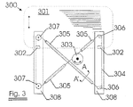
本発明に係るケーブルは、図3にその一例を示す窓昇降システム300に用いることができる。このような窓昇降システム300は、窓ガラス301を保持するクランプ素子302を備えている。クランプ素子302は本発明に係るケーブル304に取り付けられている。このケーブル304は回転装置303の回転運動を窓ガラス301の昇降運動(上昇運動または下降運動)に変換する。ケーブルの一部はケーシング305の内側を移動(滑動)する。ケーブルを比較的小さい曲げ半径で湾曲して曲げるために、取付素子308に取り付けた固定素子306またはホイール307のような案内部品を用いるとよい。
The cable according to the present invention can be used in a
本発明に係るケーブルを用いることによって、いくつかの利点が得られる。通常、ケーブルを案内素子に沿って円滑に移動させて駆動ドラムの回転運動を確実にガラスの変位に変換させるために、ケーブルに案内素子306および307を介して予備張力を付与する。この場合、ケーブルの永久伸びが大きすぎると、ケーブルが緩むことによって予備張力を減少させ、システム全体の機能障害をもたらす。しかし、本発明に係るケーブルは永久伸びが小さいので、このような問題を生じることがない。さらに、ケーシング内において滑動するケーブルのAA’面に沿った断面図である図4において示すように、ケーブル42のスチールコード41とケーシング44の金属内面43との間の金属―金属接触をなくすことができる。なお、ケーシングは、ポリマー層46によって外面を被覆された金属補強構造45である。すなわち、本発明に係るケーブルを用いる場合、ケーシングとケーブルとの間にポリマー内側ライナーを設ける必要がない。
Several advantages are obtained by using the cable according to the invention. Usually, a pretension is applied to the cable via the
上記の利点は本発明のケーブルをケーシング内において移動させる他の目的、例えば、スクータおよび二輪車のブレーキの開閉動作を行なう用途に用いた場合にも得られる。また、本発明の上述のケーブルと同一のケーブルをコントロールケーブル用途や、ホイスト、タイミングベルト、平ベルト、またはVベルトのような静的または動的用途、エレベータのドアシステムに用いるケーブル、ミラーケーブル、ブレーキケーブル、フードおよびトランク開閉ケーブルなどにも用いることができる。 The above-mentioned advantages can be obtained when the cable of the present invention is used for other purposes such as moving the brake in a casing, such as a scooter and a motorcycle brake opening / closing operation. In addition, the same cable as the above-mentioned cable of the present invention is used for a control cable, a static or dynamic application such as a hoist, a timing belt, a flat belt, or a V belt, a cable used for an elevator door system, a mirror cable, It can also be used for brake cables, hoods and trunk opening / closing cables.
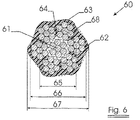
図6は本発明に係る他のケーブルを示している。ケーブル60は、複数本のスチールフィラメントからなる1本のコアストランド61の周囲を、各々が7本のスチールフィラメント62からなる6本のストランドのジャケット層によって包囲することによって得られるスチールコードを有している。このコードは図1に示すコードと実質的に同様の構成を有している。異なる点はポリマー層63が円形の断面を有せず、用いたコードの外形と同様の外形の断面を基本的に有している点にある。あるいは、円形以外の他の外形であってもよい。ケーブルはケーブル見掛け直径67を有し、コードはコード見掛け直径66を有している。図示するように、コードのジャケット層円68の径方向内側の空隙64にポリマー材料63が充填されている。好ましくは、空隙の少なくとも30%がポリマーによって充填されるとよい。さらに好ましくは、ポリマー材料としてポリウレタンが用いられるとよい。スチールとポリマー材料との間に化学的な結合が生じるようにポリマー材料が充填されるとよい。
FIG. 6 shows another cable according to the present invention. The
Claims (17)
The window lifting system according to claim 16, wherein the window lifting system further comprises a casing.
Applications Claiming Priority (2)
| Application Number | Priority Date | Filing Date | Title |
|---|---|---|---|
| EP01204515A EP1314813A1 (en) | 2001-11-23 | 2001-11-23 | Cable and window elevator system using such cable |
| PCT/EP2002/013182 WO2003044267A1 (en) | 2001-11-23 | 2002-11-22 | Cable and window elevator system using such cable |
Publications (1)
| Publication Number | Publication Date |
|---|---|
| JP2005509762A true JP2005509762A (en) | 2005-04-14 |
Family
ID=8181287
Family Applications (1)
| Application Number | Title | Priority Date | Filing Date |
|---|---|---|---|
| JP2003545877A Pending JP2005509762A (en) | 2001-11-23 | 2002-11-22 | Cable and window lifting system using cable |
Country Status (14)
| Country | Link |
|---|---|
| US (1) | US7770328B2 (en) |
| EP (2) | EP1314813A1 (en) |
| JP (1) | JP2005509762A (en) |
| KR (1) | KR100959840B1 (en) |
| CN (1) | CN100396845C (en) |
| AT (1) | ATE393854T1 (en) |
| AU (1) | AU2002363858A1 (en) |
| BR (1) | BR0214379B1 (en) |
| CA (1) | CA2466623A1 (en) |
| DE (1) | DE60226339T2 (en) |
| ES (1) | ES2305343T3 (en) |
| MX (1) | MXPA04004910A (en) |
| PL (1) | PL198447B1 (en) |
| WO (1) | WO2003044267A1 (en) |
Cited By (1)
| Publication number | Priority date | Publication date | Assignee | Title |
|---|---|---|---|---|
| JP2010515833A (en) * | 2007-01-08 | 2010-05-13 | ナムローゼ・フェンノートシャップ・ベーカート・ソシエテ・アノニム | Cable with low structural elongation |
Families Citing this family (32)
| Publication number | Priority date | Publication date | Assignee | Title |
|---|---|---|---|---|
| WO2002088502A1 (en) | 2001-04-26 | 2002-11-07 | Intier Automotive Closures Inc. | Universal cable window regulator assembly for vehicles |
| ES2286400T3 (en) * | 2003-07-16 | 2007-12-01 | Brugg Drahtseil Ag | LONGITUDINAL ELEMENT IN MOVEMENT, ESPECIALLY A LONGITUDINAL ELEMENT OF ELEVATOR OR CRANE OR SIMILAR. |
| US20060053945A1 (en) * | 2004-07-13 | 2006-03-16 | Markel Corporation | Cable assemblies with sound abatement layer |
| DE102004061385B4 (en) * | 2004-12-21 | 2007-11-29 | W.H. Küster GmbH & Co KG | Pulling rope with plastic filling and plastic outer sheath |
| CN101243225B (en) * | 2005-08-19 | 2011-08-10 | 贝卡尔特股份有限公司 | A polymer impregnated steel cord and impregnation method thereof |
| SI1963543T1 (en) | 2005-12-21 | 2012-06-29 | Bekaert Sa Nv | A steel wire rope for use in a drive system |
| US20080211730A1 (en) | 2007-01-26 | 2008-09-04 | Woosnam Calvin H | Gimbaled Mount System for Satellites |
| US20090226177A1 (en) * | 2007-01-26 | 2009-09-10 | Woosnam Calvin H | Communications Cable and Method of Making Same |
| JP2009167545A (en) * | 2008-01-11 | 2009-07-30 | Toshiba Elevator Co Ltd | Wire rope |
| DE102008037537B4 (en) * | 2008-11-10 | 2020-11-05 | Contitech Antriebssysteme Gmbh | Traction drive and elevator system with this traction drive |
| DE102008037538A1 (en) * | 2008-11-10 | 2010-05-12 | Contitech Antriebssysteme Gmbh | Traction system for an elevator installation |
| DE102008037536A1 (en) * | 2008-11-10 | 2010-05-12 | Contitech Antriebssysteme Gmbh | Traction means, traction drive with this traction device and elevator system |
| WO2010071061A1 (en) * | 2008-12-17 | 2010-06-24 | 三菱電機株式会社 | Rope for elevator |
| DE102009041706A1 (en) * | 2009-09-16 | 2011-03-24 | GM Global Technology Operations, Inc., Detroit | Connection device for a control cable and transmission of a motor vehicle with this attachment device |
| FR2962455B1 (en) * | 2010-05-20 | 2012-09-21 | Soc Tech Michelin | MULTILAYER METALLIC CABLE GUM IN SITU BY UNSATURATED THERMOPLASTIC ELASTOMER |
| JP5269838B2 (en) * | 2010-07-12 | 2013-08-21 | 株式会社日立製作所 | Elevator wire rope |
| EP2615054B1 (en) * | 2010-09-09 | 2018-06-06 | Mitsubishi Electric Corporation | Rope for elevator |
| EP2697147B1 (en) | 2011-04-14 | 2020-11-25 | Otis Elevator Company | Coated rope or belt for elevator systems |
| US20120291356A1 (en) * | 2011-05-17 | 2012-11-22 | First Dome Corporation | Synchronous drive device for slide cover mechanism |
| US20130081508A1 (en) * | 2011-09-29 | 2013-04-04 | Shimano Inc. | Bicycle control cable |
| CN103874797B (en) * | 2011-10-13 | 2016-05-25 | 贝卡尔特公司 | A kind of bearing assembly and manufacture method thereof that comprises steel wire rope and sheath |
| CN102359543A (en) * | 2011-10-20 | 2012-02-22 | 无锡通用钢绳有限公司 | Flat steel strip for elevator |
| CN103088682A (en) * | 2011-10-28 | 2013-05-08 | 常州瑞通新型线材有限公司 | Plastic-covered steel wire |
| CA2853644A1 (en) | 2011-11-28 | 2013-06-06 | Nv Bekaert Sa | Steel cord for extrusion process, an apparatus and method and use of said steel cord |
| IN2014DN07200A (en) | 2012-04-24 | 2015-04-24 | Bekaert Sa Nv | |
| IN2015DN00945A (en) * | 2012-10-05 | 2015-06-12 | Bekaert Sa Nv | |
| KR102206177B1 (en) | 2014-07-01 | 2021-01-22 | 엘지전자 주식회사 | Compressor and assembly method thereof |
| DE102015222272A1 (en) * | 2015-11-12 | 2017-05-18 | Contitech Transportbandsysteme Gmbh | Method for producing a tension member and tension members |
| WO2018015173A1 (en) | 2016-07-19 | 2018-01-25 | Bekaert Advanced Cords Aalter Nv | An evelator tension member with a hard thermoplastic polyurethane elastomer jacket |
| US11066783B2 (en) * | 2018-09-17 | 2021-07-20 | Leggett & Platt Canada Co. | Corrosion resistant cable |
| CN109853278B (en) * | 2019-04-16 | 2024-01-30 | 中国科学院海洋研究所 | Rope capable of preventing organisms from adhering |
| FR3103501B1 (en) * | 2019-11-22 | 2021-10-29 | Reel | HYBRID LIFTING CABLE, PROCESS FOR ITS REALIZATION AND CAPSTAN WINCH IMPLEMENTING SUCH A CABLE |
Family Cites Families (20)
| Publication number | Priority date | Publication date | Assignee | Title |
|---|---|---|---|---|
| DE1904468A1 (en) * | 1969-01-30 | 1970-08-27 | Berkenhoff & Drebes Ag | Bonding a plastic casing to a wire cable |
| US3634607A (en) * | 1970-06-18 | 1972-01-11 | Coleman Cable & Wire Co | Armored cable |
| US3800522A (en) * | 1971-03-30 | 1974-04-02 | Bethlehem Steel Corp | Sealed wire rope and strand and method of making |
| GB1563712A (en) * | 1977-11-02 | 1980-03-26 | Bowden Controls Ltd | Wire cables |
| US4344278A (en) * | 1980-05-30 | 1982-08-17 | Projected Lubricants, Inc. | Lubricated wire rope |
| US4523804A (en) * | 1982-08-17 | 1985-06-18 | Chevron Research Company | Armored optical fiber cable |
| US4522464A (en) * | 1982-08-17 | 1985-06-11 | Chevron Research Company | Armored cable containing a hermetically sealed tube incorporating an optical fiber |
| DE3344985A1 (en) * | 1983-12-13 | 1985-06-20 | August Rich. Dietz & Sohn Draht- u.Hanfseilwerk, 8632 Neustadt | Wire rope having a plastic sheathing |
| US4606183A (en) * | 1984-11-20 | 1986-08-19 | Amsted Industries Incorporated | Lubricated and thermoplastic impregnated wire rope |
| US4829760A (en) * | 1987-05-04 | 1989-05-16 | N.B. Bekaert S.A. | Compact steel cord structure |
| WO1991001389A1 (en) * | 1989-07-21 | 1991-02-07 | N.V. Bekaert S.A. | Steel substrate for reinforcement of elastomers |
| US5329605A (en) * | 1992-10-27 | 1994-07-12 | At&T Bell Laboratories | Undersea armored cable |
| EP0864688A1 (en) * | 1997-03-13 | 1998-09-16 | N.V. Bekaert S.A. | Push-pull cable with polymer coating |
| FR2783585B1 (en) * | 1998-09-23 | 2000-11-17 | Trefileurope | MIXED CABLE WITH SYNTHETIC CORE FOR LIFTING OR PULLING |
| EP1137694A1 (en) * | 1998-10-15 | 2001-10-04 | N.V. Bekaert S.A. | Coated metal reinforcement element and coating methods |
| US6151833A (en) * | 1999-02-26 | 2000-11-28 | Delphi Technologies, Inc. | Extruded guide for automotive window regulator assembly |
| FR2817566B1 (en) * | 2000-12-04 | 2003-02-07 | Freyssinet Int Stup | INDIVIDUALLY PROTECTED CORD, USE THEREOF IN CONSTRUCTION, AND MANUFACTURING METHOD |
| WO2002054131A1 (en) * | 2000-12-28 | 2002-07-11 | Pirelli S.P.A. | Submarine optical cable with water-blocking filling composition |
| FR2824849B1 (en) * | 2001-05-17 | 2005-06-10 | Trefileurope | DYNAMIC CABLE HAVING IMPROVED PROPERTIES, AND METHOD AND INSTALLATION FOR MANUFACTURING SUCH A CABLE |
| US20060174606A1 (en) * | 2005-02-10 | 2006-08-10 | Stram Michael A | High static thrust valveless pulse-jet engine with forward-facing intake duct |
-
2001
- 2001-11-23 EP EP01204515A patent/EP1314813A1/en not_active Withdrawn
-
2002
- 2002-11-22 DE DE60226339T patent/DE60226339T2/en not_active Expired - Lifetime
- 2002-11-22 CN CNB028232119A patent/CN100396845C/en not_active Expired - Lifetime
- 2002-11-22 ES ES02798317T patent/ES2305343T3/en not_active Expired - Lifetime
- 2002-11-22 AU AU2002363858A patent/AU2002363858A1/en not_active Abandoned
- 2002-11-22 EP EP02798317A patent/EP1454007B1/en not_active Expired - Lifetime
- 2002-11-22 BR BRPI0214379-8A patent/BR0214379B1/en not_active IP Right Cessation
- 2002-11-22 KR KR1020047007790A patent/KR100959840B1/en active IP Right Grant
- 2002-11-22 AT AT02798317T patent/ATE393854T1/en not_active IP Right Cessation
- 2002-11-22 CA CA002466623A patent/CA2466623A1/en not_active Abandoned
- 2002-11-22 JP JP2003545877A patent/JP2005509762A/en active Pending
- 2002-11-22 PL PL369928A patent/PL198447B1/en unknown
- 2002-11-22 WO PCT/EP2002/013182 patent/WO2003044267A1/en active IP Right Grant
- 2002-11-22 MX MXPA04004910A patent/MXPA04004910A/en active IP Right Grant
- 2002-11-22 US US10/496,457 patent/US7770328B2/en not_active Expired - Fee Related
Cited By (1)
| Publication number | Priority date | Publication date | Assignee | Title |
|---|---|---|---|---|
| JP2010515833A (en) * | 2007-01-08 | 2010-05-13 | ナムローゼ・フェンノートシャップ・ベーカート・ソシエテ・アノニム | Cable with low structural elongation |
Also Published As
| Publication number | Publication date |
|---|---|
| CN100396845C (en) | 2008-06-25 |
| CN1589347A (en) | 2005-03-02 |
| US20050034375A1 (en) | 2005-02-17 |
| BR0214379A (en) | 2004-11-03 |
| EP1314813A1 (en) | 2003-05-28 |
| MXPA04004910A (en) | 2004-07-30 |
| EP1454007A1 (en) | 2004-09-08 |
| ES2305343T3 (en) | 2008-11-01 |
| AU2002363858A1 (en) | 2003-06-10 |
| KR100959840B1 (en) | 2010-05-28 |
| ATE393854T1 (en) | 2008-05-15 |
| DE60226339T2 (en) | 2009-06-10 |
| EP1454007B1 (en) | 2008-04-30 |
| WO2003044267A1 (en) | 2003-05-30 |
| BR0214379B1 (en) | 2012-11-27 |
| DE60226339D1 (en) | 2008-06-12 |
| CA2466623A1 (en) | 2003-05-30 |
| US7770328B2 (en) | 2010-08-10 |
| KR20040062639A (en) | 2004-07-07 |
| PL369928A1 (en) | 2005-05-02 |
| PL198447B1 (en) | 2008-06-30 |
Similar Documents
| Publication | Publication Date | Title |
|---|---|---|
| JP2005509762A (en) | Cable and window lifting system using cable | |
| JP6016928B2 (en) | Load bearing assembly with steel rope and jacket | |
| US7757472B2 (en) | Synthetic fiber cable and elevator installation with such a synthetic fiber cable | |
| JP5289329B2 (en) | Cable with low structural elongation | |
| EP1748104B1 (en) | A speed governor for elevators | |
| FR2532061A1 (en) | ARM OPTICAL CABLE AND METHOD FOR MANUFACTURING THE SAME | |
| WO2004037702A9 (en) | Rope for elevator | |
| JPH07150491A (en) | Hoist cable | |
| JP2011046462A (en) | Elevator device and wire rope for elevator | |
| JP2012036009A (en) | Tension member for elevator | |
| CA2567960A1 (en) | Noiseproof toothed cable | |
| JP6077941B2 (en) | Elevator wire rope | |
| JP3827610B2 (en) | Multilayer twisted wire rope | |
| JP2015037990A (en) | Elevator device | |
| EP3390701A1 (en) | Flexible rack with steel cord embedded in polymer | |
| JP5376632B2 (en) | Wire rope | |
| MXPA00010021A (en) | Cable guide roller, synthetic fibre rope suitable therefor and their use |
Legal Events
| Date | Code | Title | Description |
|---|---|---|---|
| A621 | Written request for application examination |
Free format text: JAPANESE INTERMEDIATE CODE: A621 Effective date: 20051024 |
|
| A977 | Report on retrieval |
Free format text: JAPANESE INTERMEDIATE CODE: A971007 Effective date: 20080424 |
|
| A131 | Notification of reasons for refusal |
Free format text: JAPANESE INTERMEDIATE CODE: A131 Effective date: 20080502 |
|
| A601 | Written request for extension of time |
Free format text: JAPANESE INTERMEDIATE CODE: A601 Effective date: 20080801 |
|
| A602 | Written permission of extension of time |
Free format text: JAPANESE INTERMEDIATE CODE: A602 Effective date: 20080808 |
|
| A601 | Written request for extension of time |
Free format text: JAPANESE INTERMEDIATE CODE: A601 Effective date: 20080829 |
|
| A602 | Written permission of extension of time |
Free format text: JAPANESE INTERMEDIATE CODE: A602 Effective date: 20080905 |
|
| A601 | Written request for extension of time |
Free format text: JAPANESE INTERMEDIATE CODE: A601 Effective date: 20081002 |
|
| A602 | Written permission of extension of time |
Free format text: JAPANESE INTERMEDIATE CODE: A602 Effective date: 20081009 |
|
| A521 | Request for written amendment filed |
Free format text: JAPANESE INTERMEDIATE CODE: A523 Effective date: 20081104 |
|
| A02 | Decision of refusal |
Free format text: JAPANESE INTERMEDIATE CODE: A02 Effective date: 20091023 |