EP1453189A1 - Motor - Google Patents
Motor Download PDFInfo
- Publication number
- EP1453189A1 EP1453189A1 EP02778072A EP02778072A EP1453189A1 EP 1453189 A1 EP1453189 A1 EP 1453189A1 EP 02778072 A EP02778072 A EP 02778072A EP 02778072 A EP02778072 A EP 02778072A EP 1453189 A1 EP1453189 A1 EP 1453189A1
- Authority
- EP
- European Patent Office
- Prior art keywords
- stator
- main body
- motor
- teeth
- circumference
- Prior art date
- Legal status (The legal status is an assumption and is not a legal conclusion. Google has not performed a legal analysis and makes no representation as to the accuracy of the status listed.)
- Withdrawn
Links
Images



Classifications
-
- H—ELECTRICITY
- H02—GENERATION; CONVERSION OR DISTRIBUTION OF ELECTRIC POWER
- H02K—DYNAMO-ELECTRIC MACHINES
- H02K19/00—Synchronous motors or generators
- H02K19/02—Synchronous motors
- H02K19/10—Synchronous motors for multi-phase current
- H02K19/103—Motors having windings on the stator and a variable reluctance soft-iron rotor without windings
-
- H—ELECTRICITY
- H02—GENERATION; CONVERSION OR DISTRIBUTION OF ELECTRIC POWER
- H02K—DYNAMO-ELECTRIC MACHINES
- H02K1/00—Details of the magnetic circuit
- H02K1/06—Details of the magnetic circuit characterised by the shape, form or construction
- H02K1/12—Stationary parts of the magnetic circuit
- H02K1/14—Stator cores with salient poles
- H02K1/146—Stator cores with salient poles consisting of a generally annular yoke with salient poles
- H02K1/148—Sectional cores
-
- H—ELECTRICITY
- H02—GENERATION; CONVERSION OR DISTRIBUTION OF ELECTRIC POWER
- H02K—DYNAMO-ELECTRIC MACHINES
- H02K3/00—Details of windings
- H02K3/46—Fastening of windings on the stator or rotor structure
- H02K3/52—Fastening salient pole windings or connections thereto
- H02K3/521—Fastening salient pole windings or connections thereto applicable to stators only
- H02K3/522—Fastening salient pole windings or connections thereto applicable to stators only for generally annular cores with salient poles
-
- H—ELECTRICITY
- H02—GENERATION; CONVERSION OR DISTRIBUTION OF ELECTRIC POWER
- H02K—DYNAMO-ELECTRIC MACHINES
- H02K2203/00—Specific aspects not provided for in the other groups of this subclass relating to the windings
- H02K2203/03—Machines characterised by the wiring boards, i.e. printed circuit boards or similar structures for connecting the winding terminations
Definitions
- the present invention relates to a motor that is used with short-time rating.
- Fig. 10 shows a stator structure that is incorporated in a conventional motor
- reference numeral 1 represents a stator main body
- 2 represents a rotor
- 4 represents a slot
- 17 represents a tooth having a widened portion on its tip.
- this Figure is a partial drawing that is 1/4 divided, and actually, both the stator main body and the rotor have a 360-degree circumferential shape.
- this Figure illustrates a winding specification per one phase.
- the stator main body 1 has a plurality of slots 4 and teeth 17, and a coil (not shown) is wound on each of the teeth 17 in a concentrated winding system to finally form a stator.
- a rotor 2 having a gear shape is maintained on the circumference of the stator main body 1 so as to freely rotate concentrically with the stator 1, in a manner so as to face the stator main body 1 through an air gap 19 formed on the inner circumferential side thereof.
- the motor having a stator structure of this type is referred to as a reluctance motor, and, for example, the reluctance motor shown in Fig. 10, which has eighteen slots in the stator main body with twelve teeth of the rotor, is referred to as a 18/12 reluctance motor.
- the reluctance motor is constituted by only laminated electromagnetic steel plates and coils, and the number of the teeth is eighteen that is the same as the number of the slots, and each of the teeth is individually provided with a coil in the concentrated winding system.
- torque 'T' is proportional to the square of current "i”, and is also proportional to the rate of change of winding inductance "L” by rotor position " ⁇ ".
- a tooth width "W2" on the side facing the air gap 19 of the rotor 2 outside the main body is wider than a tooth width "W1" on the slot bottom face side.
- tooth width "W2" on the surface side facing the air gap 19 is made wider is because this structure prevents the coil wound inside the slot from jumping out of the slot 4 during the rotation of the motor, and also makes it possible to increase the amount of magnetic flux that enters the stator main body 1 from the rotor 2 through the air gap 19.
- Fig. 11 shows a current-torque characteristic of the conventional reluctance motor having the stator structure shown in Fig. 10.
- the theoretical value, calculated from formula (1) is indicated by a broken line, and the measured value is indicated by a solid line. Since the torque is proportional to the square of the current as shown in formula (1), the torque characteristic is represented by the theoretical value; however, actually, the torque increasing rate becomes lower as the current increases, resulting in a characteristic as indicated by the solid line.
- the major subject with such automobiles is how to improve the mileage, and with respect to the motor to be used therein, there have been strong demands for small size and light weight.
- the motor has an abrupt temperature rise due to use with short-time rating, resulting in degradation in reliability of insulating materials and the like.
- the present invention has been devised to solve the above-mentioned problems, and its objective is to provide a motor which can prevent the occurrence of a torque reduction even at the time of overloading, can immediately reduce the temperature of the motor main body upon an increase in the temperature of the motor main body, and has a high torque with a superior heat radiating property.
- a motor comprising: a stator that is constituted by a stator main body having a plurality of slots formed on the circumference of a main body with equal intervals from each other and teeth each of which is located between the slots, and extends outward along the radial direction from the slot bottom face with the same width, and a coil bobbin that is attached to each of the teeth of the stator main body, and is formed by winding a wire around a bobbin that has been preliminarily made from an insulating material such as a resin, in a concentrated winding system; and a rotor that has a gear shape and is maintained on the circumference of the stator concentrically with the stator main body, in a manner so as to face the stator through a predetermined air gap.
- a stator that is constituted by a stator main body having a plurality of slots formed on the circumference of a main body with equal intervals from each other and teeth each of which is located between the slots, and extends outward along the
- a motor comprising: a stator that is constituted by a stator main body having a plurality of slots formed on the circumference of a main body with equal intervals from each other and teeth each of which is located between the slots, and extends outward along the radial direction from the slot bottom face with the same width, and a coil bobbin that is attached to each of the teeth of the stator main body, and is formed by winding a wire around a bobbin that has been preliminarily made from an insulating material such as a resin, in a concentrated winding system; and an embedding magnet type rotor that has a permanent magnet embedded therein, and is maintained on the circumference of the stator concentrically with the stator main body, in a manner so as to face the stator through a predetermined air gap.
- a stator that is constituted by a stator main body having a plurality of slots formed on the circumference of a main body with equal intervals from each other and teeth each of which is located between the slots
- a motor comprising: a stator that is constituted by a stator main body having a plurality of slots formed on the circumference of a main body with equal intervals from each other and teeth each of which is located between the slots, and extends outward along the radial direction from the slot bottom face with the same width; and a coil bobbin that is attached to each of the teeth of the stator main body, and is formed by winding a wire around a bobbin that has been preliminarily made from an insulating material such as a resin, in a concentrated winding system, and a coil bobbin that is attached to each of the teeth of the stator main body, and is formed by winding a wire around a bobbin that has been preliminarily made from an insulating material such as a resin, in a concentrated winding system; and a surface magnet type rotor that is maintained on the circumference of the stator concentrically with the stator main body, in a
- a motor comprising: a stator that is constituted by a stator main body having a plurality of slots formed on the circumference of a main body with equal intervals from each other and teeth each of which is located between the slots, and extends outward along the radial direction from the slot bottom face with the same width, and a coil bobbin that is attached to each of the teeth of the stator main body, and is formed by winding a wire around a bobbin that has been preliminarily made from an insulating material such as a resin, in a concentrated winding system, and a coil bobbin that is attached to each of the teeth of the stator main body, and is formed by winding a wire around a bobbin that has been preliminarily made from an insulating material such as a resin, in a concentrated winding system; and a rotor that has a plurality of slits formed therein, and is maintained on the circumference of the stator
- a fifth aspect of the present invention relates to a motor in accordance with any one of the first to fourth aspects, and this motor is constituted by connection-use end plates formed by coating wire connections and conduction plates with an insulating material. With this arrangement, it becomes possible to suppress heat generation from the connected portion even upon application of a large current.
- a sixth aspect of the present invention relates to a motor in accordance with any one of the first to fifth aspects, and this motor is characterized in that the stator is entirely molded by a resin; thus, it becomes possible to improve the heat radiating performance of the motor.
- a seventh aspect of the present invention relates to a motor in accordance with any one of the first to sixth aspects, and this motor is characterized in that the rotor is molded by a resin; thus, it becomes possible to improve the heat radiating performance of the motor.
- An eighth aspect of the present invention relates to a motor that is used with short-time rating, and this motor is characterized by having the structure in accordance with any one of the first to seventh aspects; thus, even at the time of an abrupt temperature rise in the motor main body, it becomes possible to lower the temperature of the motor main body immediately after the motor stop.
- a ninth aspect of the present invention relates to an automobile that is equipped with a motor in accordance with any one of the first to eighth aspects; thus, it becomes possible to improve the mileage of the automobile.
- Fig. 1 shows a stator of the present invention
- reference numeral 3 is a tooth
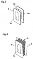
- 5 is a bobbin
- 6 is a wire
- 7 is a coil bobbin
- 8 is a connection-use end plate
- 9 is a conductor plate
- 20 is a stator.
- the bobbins 5 are attached to a stator main body 1 (see Fig. 4) in the radial direction thereof, and each of the bobbins 5 is constituted by an end face wall 5a that defines both of the end faces in the radial direction and prevents overflow (protrusion toward the stator outer diameter side) of the wire 6 when wound around it, a winding portion 5b on which the wire 6 is wound and an attaching hole 5c that allows the attachment to tooth 3 (see Fig. 2).
- Fig. 3 shows a coil bobbin 7 in which the wire 6 is wound around the bobbin 5 as an alignment roll. Moreover, with respect to the wire 6, the winding start portion and the winding end portion are taken out in the same direction so that the connections of the wire 6 are made on one side face of the stator 1.
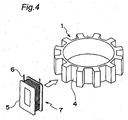
- Fig. 4 shows a stator main body 1 prior to the attachment of the coil bobbin 7.
- the width "W" of the tooth 3 is the same from the bottom face side of the slot 4 to the outside end in the radial direction; however, with this arrangement of the coil bobbin 7, even in the case of the stator main body 1 with a fixed width of the tooth 3, it is possible to secure the wire 6 without causing the wire 6 inside the slot 4 to protrude on the air gap 19 side of the rotor 2.
- this motor is a reluctance motor of a so-called outer rotor type, it is possible to easily attach the coil bobbin 7.
- Fig. 5 shows a connection state between the wires 6 and a connection-use end plate 8.
- the connection-use end plate 8 has a structure in which a conductor plate 9 is integrally molded by an insulating material such as a resin, or a structure in which, as shown in Fig. 6, a conductor plate 9 is sandwiched between an upper end plate 10a and a lower end plate 10b.
- the connection between the conductor plate 9 and the wire 6 is made through a method such as soldering and fusing.
- Figs. 7 and 8 show a motor (the coil bobbin 7 and the connection-use end plate 8 of which are not shown) that is an embodiment of the present invention, and this motor is a so-called reluctance motor that has a rotor 2, which has a gear shape and is maintained on the circumference of the stator 20 concentrically with the stator main body 1, in a manner so as to face the stator 20 through an air gap 19.
- Fig. 7 is a partial drawing that is 1/4 divided, and actually, both the stator main body and the rotor have a 360-degree circumferential shape.
- the width "W" of the tooth 3 of the stator main body 1 is made to have the same value from the slot bottom portion to the air gap surface portion so that it is possible to eliminate magnetic saturation (generated at portion "A” of Fig. 10) that has been caused in a conventional reluctance motor, to alleviate torque saturation in the overload, and consequently to achieve a reluctance motor with high torque.
- Fig. 9 shows a relationship between the torque and the current in the present invention. Since the motor of the present invention alleviates magnetic saturation, it becomes possible to achieve a motor which has a greater torque constant in comparison with the conventional stator.
- stator 20 for example, see Fig. 1 as described above, it becomes possible to secure the coil bobbin 7 more firmly thereto by molding its entire portion with resin; thus, it is possible to reduce vibration of the reluctance motor, and also to efficiently radiate heat generated from the coil during driving and at the time of the motor stop by using a resin having a thermal conductivity higher than that of air.
- the present invention is also applicable to an embedding magnet type synchronous motor having a permanent magnet embedded inside the rotor, a surface magnet type synchronous motor with a magnet being placed on the surface of the rotor and a synchronous reluctance motor having a plurality of slots inside the rotor, and the same effects as described above can be obtained.
- the motor of the present invention comprises: a stator that is constituted by a stator main body having a plurality of slots formed on the circumference of a main body with equal intervals from each other and teeth each of which is located between the slots, and extends outward along the radial direction from the slot bottom face with the same width, and a coil bobbin that is attached to each of the teeth of the stator main body, and is formed by winding a wire around a bobbin that has been preliminarily made from an insulating material such as a resin, in a concentrated winding system; and a rotor that has a gear shape and is maintained on the circumference of the stator concentrically with the stator main body, in a manner so as to face the stator through a predetermined air gap. Therefore, it becomes possible to provide a motor with high torque, which can alleviate magnetic saturation in the overload.
- connection of the wire can be carried out by using a connection-use end plate containing a conductor plate, it becomes possible to provide a motor with high reliability even in the case of application of a large current.
- stator or rotor or both of these can be molded with resin so that the heat radiating performance of the motor is improved with reduced vibration; thus, it becomes possible to lower the motor temperature even upon application with short-time rating.
Landscapes
- Engineering & Computer Science (AREA)
- Power Engineering (AREA)
- Insulation, Fastening Of Motor, Generator Windings (AREA)
- Manufacture Of Motors, Generators (AREA)
- Synchronous Machinery (AREA)
- Iron Core Of Rotating Electric Machines (AREA)
- Windings For Motors And Generators (AREA)
Abstract
Description
Claims (9)
- A motor comprising:a stator that is constituted by a stator main body having a plurality of slots formed on the circumference of a main body with equal intervals from each other and teeth each of which is located between the slots, and extends outward along the radial direction from the slot bottom face with the same width, and a coil bobbin that is attached to each of the teeth of the stator main body, and is formed by winding a wire around a bobbin that has been preliminarily made from an insulating material such as a resin, in a concentrated winding system; anda rotor that has a gear shape and is maintained on the circumference of the stator concentrically with the stator main body, in a manner so as to face the stator through a predetermined air gap.
- A motor comprising:a stator that is constituted by a stator main body having a plurality of slots formed on the circumference of a main body with equal intervals from each other and teeth each of which is located between the slots, and extends outward along the radial direction from the slot bottom face with the same width, and a coil bobbin that is attached to each of the teeth of the stator main body, and is formed by winding a wire around a bobbin that has been preliminarily made from an insulating material such as a resin, in a concentrated winding system; andan embedding magnet type rotor that has a permanent magnet embedded therein, and is maintained on the circumference of the stator concentrically with the stator main body, in a manner so as to face the stator through a predetermined air gap.
- A motor comprising:a stator main body having a plurality of slots formed on the circumference of a main body with equal intervals from each other and teeth each of which is located between the slots, and extends outward along the radial direction from the slot bottom face with the same width, and a coil bobbin that is attached to each of the teeth of the stator main body, and is formed by winding a wire around a bobbin that has been preliminarily made from an insulating material such as a resin, in a concentrated winding system; anda surface magnet type rotor that is maintained on the circumference of the stator concentrically with the stator main body, in a manner so as to face the stator through a predetermined air gap, with a magnet being placed on a surface on the opposing side.
- A motor comprising:a stator that is constituted by a stator main body having a plurality of slots formed on the circumference of a main body with equal intervals from each other and teeth each of which is located between the slots, and extends outward along the radial direction from the slot bottom face with the same width, and a coil bobbin that is attached to each of the teeth of the stator main body, and is formed by winding a wire around a bobbin that has been preliminarily made from an insulating material such as a resin, in a concentrated winding system; anda rotor that has a plurality of slits formed therein, and is maintained on the circumference of the stator concentrically with the stator main body, in a manner so as to face the stator through a predetermined air gap.
- The motor according to any one of claims 1 to 4, wherein connections of the wire are made using connection-use end plates formed by coating conduction plates with an insulating material.
- The motor according to any one of claims 1 to 5, wherein the stator is entirely molded by a resin.
- The motor according to any one of claims 1 to 6, wherein the rotor is molded by a resin.
- A motor, which is used with short-time rating, comprising a structure in accordance with any one of claims 1 to 7.
- An automobile comprising a motor in accordance with any one of claims 1 to 8.
Applications Claiming Priority (3)
| Application Number | Priority Date | Filing Date | Title |
|---|---|---|---|
| JP2001342907A JP2003153509A (en) | 2001-11-08 | 2001-11-08 | motor |
| JP2001342907 | 2001-11-08 | ||
| PCT/JP2002/011664 WO2003041244A1 (en) | 2001-11-08 | 2002-11-08 | Motor |
Publications (2)
| Publication Number | Publication Date |
|---|---|
| EP1453189A1 true EP1453189A1 (en) | 2004-09-01 |
| EP1453189A4 EP1453189A4 (en) | 2011-08-03 |
Family
ID=19156687
Family Applications (1)
| Application Number | Title | Priority Date | Filing Date |
|---|---|---|---|
| EP02778072A Withdrawn EP1453189A4 (en) | 2001-11-08 | 2002-11-08 | Motor |
Country Status (4)
| Country | Link |
|---|---|
| US (1) | US7218026B2 (en) |
| EP (1) | EP1453189A4 (en) |
| JP (1) | JP2003153509A (en) |
| WO (1) | WO2003041244A1 (en) |
Cited By (1)
| Publication number | Priority date | Publication date | Assignee | Title |
|---|---|---|---|---|
| EP1705776A1 (en) * | 2005-03-17 | 2006-09-27 | Zf Friedrichshafen Ag | Stator for an electrical machine |
Families Citing this family (26)
| Publication number | Priority date | Publication date | Assignee | Title |
|---|---|---|---|---|
| CN100358225C (en) * | 2002-06-26 | 2007-12-26 | 阿莫泰克有限公司 | Brushless direct-current motor of radial core type having a structure of double rotors and method for making the same |
| USD539739S1 (en) * | 2004-01-26 | 2007-04-03 | The State Of New Mexico, As Represented By The Office Of The Governor | Magnetically assisted generator shaft |
| KR20060005492A (en) * | 2004-07-13 | 2006-01-18 | 엘지전자 주식회사 | Combined wet and dry motors without cooling fans |
| JP4574454B2 (en) * | 2005-06-03 | 2010-11-04 | 三菱電機株式会社 | Electric motor |
| NO324241B1 (en) * | 2006-02-28 | 2007-09-17 | Smartmotor As | Device by electric machine |
| JP2008017639A (en) * | 2006-07-06 | 2008-01-24 | Fanuc Ltd | Electric motor and electric motor manufacturing method |
| KR101080768B1 (en) * | 2009-12-03 | 2011-11-07 | 기아자동차주식회사 | Concentrated type coil connecting structure of motor for hybrid vehicle |
| JP5703045B2 (en) * | 2011-02-02 | 2015-04-15 | 株式会社日立産機システム | Electric motor |
| GB2503500A (en) * | 2012-06-29 | 2014-01-01 | Nidec Motors & Actuators Gmbh Germany | An armature connecting wire arrangment for an electric motor |
| US20140339947A1 (en) * | 2013-05-16 | 2014-11-20 | Lasko Holdings, Inc. | Multi-Piece Stator For An Electric Motor |
| JP6044488B2 (en) * | 2013-08-30 | 2016-12-14 | トヨタ自動車株式会社 | Coil insulator fixing method and structure, stator, and rotating electric machine |
| JP6561692B2 (en) * | 2015-08-31 | 2019-08-21 | スズキ株式会社 | Rotating electric machine |
| TWI558067B (en) | 2015-09-18 | 2016-11-11 | 財團法人工業技術研究院 | Winding frame structure for motors |
| US10786894B2 (en) * | 2015-10-14 | 2020-09-29 | Black & Decker Inc. | Brushless motor system for power tools |
| CN108933485A (en) * | 2017-05-22 | 2018-12-04 | 深圳市美好创亿医疗科技有限公司 | Micromotor stator module and preparation method thereof |
| DE102017213904A1 (en) * | 2017-08-10 | 2019-02-14 | Bayerische Motoren Werke Aktiengesellschaft | rotor |
| US11411452B2 (en) | 2018-04-18 | 2022-08-09 | Panasonic Intellectual Property Management Co., Ltd. | Coil and motor using same |
| JP7211586B2 (en) * | 2018-09-28 | 2023-01-24 | 日本電産サーボ株式会社 | motor |
| JP7147629B2 (en) * | 2019-02-25 | 2022-10-05 | 株式会社デンソー | Armature and rotating electric machine |
| JP2020137369A (en) * | 2019-02-25 | 2020-08-31 | 株式会社デンソー | Armature and rotary electric machine |
| WO2022058939A1 (en) | 2020-09-21 | 2022-03-24 | Evr Motors Ltd. | Radial flux electric machine |
| US12081073B2 (en) | 2021-10-04 | 2024-09-03 | Evr Motors Ltd | Electric machine with multi-tapered yokes |
| GB2616461A (en) * | 2022-03-10 | 2023-09-13 | Protean Electric Ltd | A bobbin |
| US12278519B1 (en) | 2023-12-28 | 2025-04-15 | Evr Motors Ltd | Electric machine with multiple toothed spacers in coils |
| US12136869B1 (en) | 2023-12-28 | 2024-11-05 | Evr Motors Ltd | Heat dissipation plate for electric machine |
| US12046949B1 (en) | 2023-12-28 | 2024-07-23 | Evr Motors Ltd | Electric machine with coils bridged with toothed clips |
Family Cites Families (22)
| Publication number | Priority date | Publication date | Assignee | Title |
|---|---|---|---|---|
| JPS55117449A (en) * | 1979-03-05 | 1980-09-09 | Hitachi Ltd | Structure of stator of magnetic generator |
| JPS56110788U (en) * | 1980-01-25 | 1981-08-27 | ||
| JPS56110788A (en) | 1980-02-06 | 1981-09-02 | Kawasaki Heavy Ind Ltd | Manufacture of molten pig iron and valuable gas by utilizing coke powder |
| JPH03143238A (en) * | 1989-10-25 | 1991-06-18 | Aichi Emerson Electric Co Ltd | Rotor |
| JPH0576146A (en) * | 1991-06-10 | 1993-03-26 | Shinko Electric Co Ltd | AC servo motor |
| JPH05207718A (en) * | 1992-01-24 | 1993-08-13 | Nippon Densan Corp | DC motor |
| JPH05308742A (en) | 1992-04-28 | 1993-11-19 | Yaskawa Electric Corp | Stator winding connection method |
| JPH0759317A (en) | 1993-08-18 | 1995-03-03 | Shibaura Eng Works Co Ltd | motor |
| JPH08186967A (en) | 1994-12-28 | 1996-07-16 | Matsushita Electric Ind Co Ltd | Reluctance motor |
| JP3312370B2 (en) * | 1995-03-28 | 2002-08-05 | ミネベア株式会社 | Motor structure |
| JP3534889B2 (en) * | 1995-04-26 | 2004-06-07 | ミネベア株式会社 | Stator structure of rotating electric machine |
| JP3376373B2 (en) * | 1995-06-07 | 2003-02-10 | ミネベア株式会社 | Motor structure |
| JP3661247B2 (en) | 1995-11-07 | 2005-06-15 | 株式会社日立製作所 | Abduction type rotating electrical machine |
| JPH09308142A (en) * | 1996-05-20 | 1997-11-28 | Yaskawa Electric Corp | Rotating electric machine |
| JP4005169B2 (en) * | 1997-04-11 | 2007-11-07 | 東芝キヤリア株式会社 | Compressor |
| TW380329B (en) * | 1997-04-16 | 2000-01-21 | Japan Servo | Permanent-magnet revolving electrodynamic machine with a concentrated winding stator |
| JP3425326B2 (en) | 1997-05-29 | 2003-07-14 | オークマ株式会社 | Synchronous motor |
| JP3535012B2 (en) * | 1998-06-09 | 2004-06-07 | ミネベア株式会社 | Radial gap type small cylindrical rotating electric machine |
| JP3421251B2 (en) * | 1998-08-21 | 2003-06-30 | ミネベア株式会社 | Rotating electric machine and its bobbin |
| JP2001292542A (en) * | 2000-04-05 | 2001-10-19 | Nissan Motor Co Ltd | Method for manufacturing stator core of electric motor and stator |
| US6566779B2 (en) * | 2000-06-02 | 2003-05-20 | Kabushiki Kaisha Moric | Coil winding for DC machine |
| JP2002354733A (en) * | 2001-03-19 | 2002-12-06 | Denso Corp | DC motor |
-
2001
- 2001-11-08 JP JP2001342907A patent/JP2003153509A/en active Pending
-
2002
- 2002-11-08 EP EP02778072A patent/EP1453189A4/en not_active Withdrawn
- 2002-11-08 WO PCT/JP2002/011664 patent/WO2003041244A1/en not_active Ceased
- 2002-11-08 US US10/494,600 patent/US7218026B2/en not_active Expired - Fee Related
Cited By (1)
| Publication number | Priority date | Publication date | Assignee | Title |
|---|---|---|---|---|
| EP1705776A1 (en) * | 2005-03-17 | 2006-09-27 | Zf Friedrichshafen Ag | Stator for an electrical machine |
Also Published As
| Publication number | Publication date |
|---|---|
| JP2003153509A (en) | 2003-05-23 |
| US7218026B2 (en) | 2007-05-15 |
| WO2003041244A1 (en) | 2003-05-15 |
| EP1453189A4 (en) | 2011-08-03 |
| US20050035680A1 (en) | 2005-02-17 |
Similar Documents
| Publication | Publication Date | Title |
|---|---|---|
| US7218026B2 (en) | Motor | |
| US7081697B2 (en) | Dynamoelectric machine stator core with mini caps | |
| US6566779B2 (en) | Coil winding for DC machine | |
| US20090184599A1 (en) | Alternator for Vehicle, Vehicle Equipped with Alternator, Method for Manufacturing Alternator for Vehicle, and Rotating Electric Machine for Vehicle | |
| JP7363379B2 (en) | Control device and rotating electrical machine system | |
| US20090085415A1 (en) | Stator assembly for an electric machine and method of manufacturing the same | |
| US6137198A (en) | Stator for a magneto generator | |
| JP5506836B2 (en) | Magnet generator | |
| EP1009091A2 (en) | Actuator device with valve | |
| JP3819386B2 (en) | Magnet generator | |
| WO2013118777A1 (en) | Magnet generator | |
| JP4081444B2 (en) | Alternators, especially automotive alternators | |
| JP4535147B2 (en) | Rotating electric machine stator and rotating electric machine | |
| EP1168570A2 (en) | Coil winding for DC machine | |
| JP4140854B2 (en) | Rotating electrical machine rotor | |
| US20250192636A1 (en) | A bobbin | |
| JP2000316246A (en) | Core insulating member and motor having the same | |
| JP5315740B2 (en) | Linear actuator coil device and linear actuator | |
| JP2006325318A (en) | Commutator, motor, and manufacturing method of motor | |
| JP5884464B2 (en) | Rotating electric machine | |
| JPH0436225Y2 (en) | ||
| JP4640851B2 (en) | Magnet generator | |
| JP4235431B2 (en) | Single-phase magnet generator | |
| EP1589639A1 (en) | Improved multipolar magnetogenerator charging system | |
| JP2012239262A (en) | Salient pole concentrated winding stator for motor |
Legal Events
| Date | Code | Title | Description |
|---|---|---|---|
| PUAI | Public reference made under article 153(3) epc to a published international application that has entered the european phase |
Free format text: ORIGINAL CODE: 0009012 |
|
| 17P | Request for examination filed |
Effective date: 20040525 |
|
| AK | Designated contracting states |
Kind code of ref document: A1 Designated state(s): AT BE BG CH CY CZ DE DK EE ES FI FR GB GR IE IT LI LU MC NL PT SE SK TR |
|
| AX | Request for extension of the european patent |
Extension state: AL LT LV MK RO SI |
|
| RAP1 | Party data changed (applicant data changed or rights of an application transferred) |
Owner name: PANASONIC CORPORATION |
|
| A4 | Supplementary search report drawn up and despatched |
Effective date: 20110705 |
|
| RIC1 | Information provided on ipc code assigned before grant |
Ipc: H02K 1/16 20060101ALI20110629BHEP Ipc: H02K 3/46 20060101ALI20110629BHEP Ipc: H02K 19/10 20060101AFI20110629BHEP |
|
| STAA | Information on the status of an ep patent application or granted ep patent |
Free format text: STATUS: THE APPLICATION IS DEEMED TO BE WITHDRAWN |
|
| 18D | Application deemed to be withdrawn |
Effective date: 20111005 |