JP5703045B2 - Electric motor - Google Patents
Electric motor Download PDFInfo
- Publication number
- JP5703045B2 JP5703045B2 JP2011020294A JP2011020294A JP5703045B2 JP 5703045 B2 JP5703045 B2 JP 5703045B2 JP 2011020294 A JP2011020294 A JP 2011020294A JP 2011020294 A JP2011020294 A JP 2011020294A JP 5703045 B2 JP5703045 B2 JP 5703045B2
- Authority
- JP
- Japan
- Prior art keywords
- bobbin holder
- stator core
- stator
- electric motor
- bobbin
- Prior art date
- Legal status (The legal status is an assumption and is not a legal conclusion. Google has not performed a legal analysis and makes no representation as to the accuracy of the status listed.)
- Active
Links
Images


Landscapes
- Iron Core Of Rotating Electric Machines (AREA)
- Insulation, Fastening Of Motor, Generator Windings (AREA)
- Permanent Magnet Type Synchronous Machine (AREA)
Description
本発明は電動機に関する。 The present invention relates to an electric motor.
本技術分野の背景技術として特許文献1がある。この文献には「ティースコアのティース部に被嵌する巻線ボビンの中空部壁面に突部を一体形成し、巻線ボビン被嵌時に突部の押し潰しにより巻線ボビンの固定保持を図る」と記載されている(例えば、要約書、明細書0008等参照)。また、別の背景技術として特許文献2がある。この文献には「巻線の絶縁をするためのボビンに積厚方向に凸部を設け、かつ、ボビン形状は内径側寸法と外形側寸法は同一として、ティース部先端の両側に設けられた凹部にボビンの凸部が嵌合するようにした。」と記載されている。
There is
固定子の巻線に関しては、上述の特許文献1〜2に示されるように、巻線がボビンに巻かれた状態でティースに取り付けられる構成が知られている。このような巻線方式を採用する際には、ボビンとティースとの固定方法が問題となる。
Regarding the winding of the stator, as shown in
上述のように、特許文献1および2には、ボビンとティースとの固定方法が記載されているが、特許文献1のボビン固定方法は、固定後に応力が残存してしまうため、耐久性に悪影響を与える場合がある。また、特許文献2のボビン固定方法は、ティースの形状を変化させているため、磁気特性に悪影響を与える場合がある。
As described above,
また、特許文献1には、位置決めのために複数のボビンと当接するプリント版を備えているが、ボビンとティースとの固定を意図したものではない。
Moreover, although
そこで、本発明は、電動機の耐久性や特性に悪影響を与えることなくボビンとティースを固定可能な構造を提供することを目的とする。 Accordingly, an object of the present invention is to provide a structure capable of fixing a bobbin and a tooth without adversely affecting the durability and characteristics of the electric motor.
上記目的を達成するための本発明の電動機は、複数のティース部を円周方向に有する固定子鉄心と固定子巻線が巻き回されて前記ティース部に挿入される中空形状の絶縁材と、複数の前記絶縁材と勘合してこれらを固定子鉄心に固定するボビンホルダと、を備え、
前記絶縁材は、前記ティース部に挿入される方向に延伸する延伸部先端に突起物を有し、
前記ボビンホルダは、前記固定子鉄心の一側端面に固定されるものであり、前記突起物と噛み合って前記絶縁材を前記固定子鉄心に固定するものとした。
In order to achieve the above object, the electric motor of the present invention includes a stator core having a plurality of teeth portions in the circumferential direction and a hollow insulating material wound around the stator windings and inserted into the teeth portions, A bobbin holder for fitting with a plurality of the insulating materials and fixing them to the stator core,
The insulating material has a protrusion at the end of the extending portion that extends in the direction of insertion into the teeth portion,
The bobbin holder is fixed to one end face of the stator core, and meshes with the protrusions to fix the insulating material to the stator core .
上記の本発明の構成においてより好ましい具体的態様は下記の通りである。
(1)少なくとも2つのボビンホルダが、複数の前記ティース部の円周方向配列に沿うように一体成形されてなるものであること。
(2)前記絶縁材は、前記延伸部が前記固定子鉄心の一側端面に並ぶように挿入され、前記延伸部は、前記一側端面に配置され、
前記固定子鉄心を鋼板の積層前記一側端面から回転軸方向に貫通するボルトが、前記固定子鉄心の前記一側端面にヘッドが位置するように設けられ、
前記ボビンホルダは、前記ヘッドと、前記固定子巻線との接触を防ぐ防壁を有すること。
(3)前記ボビンホルダを回転軸方向から覆うカバーを有し、前記カバーと、固定子とを固定することで前記ボビンホルダを前記固定子鉄心に固定すること。
(4)前記ボビンホルダは円周方向に複数に分割されるものであること
(5)前記固定子鉄心は、分割鉄心からなるものであり、該固定子鉄心の分割位置と、前記ボビンホルダの円周方向の分割位置とが一致するものであること。
(6)前記固定子鉄心は円周方向の外周側に突出する複数のティース部を有するものであり、前記ティース部の外周側に円筒状の回転子を備えるアウターロータ型の電動機であり、前記回転子は複数に分割された回転子コアから構成され、かつ、前記回転子コアの内表面に磁石を配置したこと。
(7)前記ボビンホルダが、絶縁樹脂からなるものであること。
In the above-described configuration of the present invention, more preferred specific embodiments are as follows.
(1) At least two bobbin holders are integrally formed so as to follow the circumferential arrangement of the plurality of tooth portions.
(2) The insulating material is inserted so that the extending portion is aligned with one end surface of the stator core, and the extending portion is disposed on the one end surface,
A bolt that penetrates the stator core in the direction of the rotation axis from the one side end face of the steel sheet is provided such that a head is positioned on the one end face of the stator core,
The bobbin holder has a barrier to prevent contact between the head and the stator winding.
(3) A cover for covering the bobbin holder from the rotation axis direction is provided, and the bobbin holder is fixed to the stator core by fixing the cover and the stator.
(4) The bobbin holder is divided into a plurality in the circumferential direction.
(5) The stator core is composed of a split core, and the split position of the stator core matches the split position in the circumferential direction of the bobbin holder.
(6) The stator iron core has a plurality of tooth portions projecting to the outer circumferential side in the circumferential direction, and is an outer rotor type electric motor including a cylindrical rotor on the outer circumferential side of the teeth portion, The rotor is composed of a rotor core divided into a plurality of parts, and a magnet is disposed on the inner surface of the rotor core.
(7) The bobbin holder is made of an insulating resin.
本発明によれば、電動機の耐久性や特性に影響を与えずにボビンの固定を行うことのできる構造を提供することができる。上記した以外の課題、構成及び効果は、以下の実施形態の説明により明らかにされる。 ADVANTAGE OF THE INVENTION According to this invention, the structure which can fix a bobbin, without affecting the durability and characteristic of an electric motor can be provided. Problems, configurations, and effects other than those described above will be clarified by the following description of embodiments.
本発明の実施形態は、固定子巻線が絶縁材に巻き回された状態で、固定子鉄心の矩形状のティースに挿入され、集中巻のコイルを構成する固定子を前提とする。この構成において、固定子巻線が巻き回された絶縁材の先端に突起物を設けている。絶縁材はティースごとに円周方向に複数存在しており、これらの絶縁材の突起物と噛み合う勘合部を構成した部材を設けている。これによって、当該部材の勘合部と絶縁材の突起物との組み合わせにより、絶縁材が固定子より脱落することが防止されるようになっている。 The embodiment of the present invention is premised on a stator that is inserted into a rectangular tooth of a stator core and constitutes a concentrated winding coil in a state in which the stator winding is wound around an insulating material. In this configuration, a protrusion is provided at the tip of the insulating material around which the stator winding is wound. A plurality of insulating materials exist in the circumferential direction for each tooth, and a member constituting a fitting portion that meshes with the protrusions of these insulating materials is provided. Thus, the combination of the fitting portion of the member and the protrusion of the insulating material prevents the insulating material from falling off the stator.
以下で詳細を説明する図面から明らかであるが、本実施形態では、固定子鉄心の外周側に突出するティース部を有している。回転子はこれらティース部よりもさらに外周側に位置している(図示は省略)。すなわち、いわゆるアウターロータ型の電動機を例に説明する。また、固定子鉄心は円周方向に6分割されており、各々8個のティースを有し、ステータ全体としては48個のティースを有する、いわゆる48スロットのステータを構成しているものとする。この分割は、電磁鋼板から採取する固定子鉄心の形状を略長方形とすることにより、材料使用率の向上を図っているものである。 As will be apparent from the drawings that will be described in detail below, the present embodiment has a teeth portion that protrudes to the outer peripheral side of the stator core. The rotor is located further on the outer peripheral side than these teeth portions (not shown). That is, a so-called outer rotor type electric motor will be described as an example. In addition, the stator core is divided into six in the circumferential direction, each having eight teeth, and the stator as a whole has a so-called 48-slot stator having 48 teeth. This division is intended to improve the material usage rate by making the shape of the stator core collected from the electromagnetic steel sheet into a substantially rectangular shape.
以下、本実施形態の具体例を図面を用いて説明する。図1〜6は、本実施形態の電動機の示す図である。 Hereinafter, specific examples of the present embodiment will be described with reference to the drawings. 1-6 is a figure which shows the electric motor of this embodiment.
図1は電動機のステータ部の一部を示す斜視図である。図1において、固定子鉄心1に設けられたティース部1aは外周側に突出する形状で設けられており、これらのティース部1aは絶縁材2(ボビン2)で覆われている。この絶縁材2には固定子巻線3が巻き回されて、いわゆる集中巻のコイルを構成している。また、絶縁材2は、中空矩形の形状をなしており、ティース部1aに挿入される方向に延伸部2aが設けられ、その先端部にはT字状の突起物2a’を有している。
FIG. 1 is a perspective view showing a part of a stator portion of an electric motor. In FIG. 1, a tooth portion 1 a provided on the
この延伸部2aは固定子鉄心1の一方の側に設けられ、他方の側には設けられていない。以下の説明では、特にことわりの無い限り、積層鋼板の積厚方向(回転軸の延伸方向)において、延伸部2aが設けられている側を上方とし、他側を下方ということとする。
The extending
図1では、最も左側に位置する絶縁材2がティース部1aから離れた位置に存在しているが、これは固定子鉄心1に取り付けられる前の状態を示したものである。実際の取り付けの際には、図1に示されるように、絶縁材2の外周に固定子巻線3が巻き回された状態で、ティース部1aに挿入される。その際、複数の絶縁材2が放射状に並ぶため、突起物2aが固定子鉄心1の中心側で円周方向に整列することになる。このように延伸部2aが固定子鉄心1の一側に並ぶ状態とすることで、本実施形態による固定方法が行いやすいものとなっている。
In FIG. 1, the leftmost
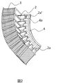
図2は図1のA矢視図である。説明の便宜上、固定子鉄心1は省いた図となっている。すなわち、絶縁材2を下方から見た図となっている。図2おいて、絶縁材2を固定する機能を設けた円弧状の部材4(以下、ボビンホルダ4という。)には、放射状に複数の突起物4aが設けられており、突起物4aはボビン2のT字状の突起物2a’と噛み合うようT字状を成している。このように,一個のボビンホルダ4に対して8個のボビン2が各々の突起物にて勘合して固定されている。
FIG. 2 is a view taken in the direction of arrow A in FIG. For convenience of explanation, the
この固定は、絶縁材2が全てティース部1aに取り付けられた状態でボビンホルダ4を固定子鉄心1の鋼板の積層方向上方から挿入することで行う。一度ボビンホルダ4の突起物4aと各絶縁材2の突起物2aとが勘合されると、後述するように絶縁材2aの抜け防止が可能となる。なお、ボビンホルダ4の材質は樹脂等の絶縁材が好ましい。この理由は後述する。
This fixing is performed by inserting the
図3はボビンホルダ4の上方斜視図である。ボビンホルダ4の上方側の表面には突出する防壁4bがティース部1aと同数設けられ、防壁4bで囲まれる内部は開口部となっている。T字状の突起物4aはボビンホルダ4の下側に設けられているため、ボビンホルダ4が上方から取り付けられることで、絶縁材2の固定が行われる。
FIG. 3 is a top perspective view of the
図4はボビンホルダ4の下方斜視図である。絶縁材2の突起物2a’と勘合する突起物4aが各開口部の間に存在している。
FIG. 4 is a lower perspective view of the
これら図3、図4に示すように、ボビンホルダ4は分割された固定子鉄心1のそれぞれに対応しており、分割位置も合わせられるように組み上げられる。このため、固定子鉄心1の各パーツごとに組立て可能となっている。
As shown in FIGS. 3 and 4, the
図5はボビンホルダ4が取り付けられた状態の上面図であり、本実施形態の構成による効果説明図である。図5に示すように、固定子の上面側には固定子巻線3の内周側にコイルガイド突起2bが絶縁材2の延伸部2aに設けられており、さらに内周側にボビンホルダ4が位置している(コイルガイド突起2aについては後述)。
FIG. 5 is a top view of the state in which the
図5において、固定子巻線3が巻き回されたボビン2の1つが固定子鉄心1から抜け出る方向に外力F1が加わった場合、当該ボビン2のT字の突起物2aとボビンホルダ4の突起物4aが噛み合っているため、ボビンホルダ4に同一方向の力F2、F3がかかる。また、他の7個のボビン2にも同一方向の力F4がかかるが、ボビン2はティースに沿う方向bへしか移動できず,各々のボビン2の移動方向が異なるため、他の7個のボビン2により外力を受けたボビン2の移動が阻害される。このため,ボビン2は抜け出せない。
In FIG. 5, when an external force F <b> 1 is applied in a direction in which one of the
このような固定方法を採用すれば、応力の残存も無く、ティースの形状も変更させずに済むため、耐久性や磁気特性に影響を及ぼさずにボビン(絶縁材2)を固定することが可能となる。 By adopting such a fixing method, there is no residual stress and it is not necessary to change the shape of the teeth, so it is possible to fix the bobbin (insulating material 2) without affecting the durability and magnetic properties. It becomes.
また、絶縁材2が固定子鉄心1から抜け出るのを防止するためにティース部1aの先端を絶縁材2の幅よりも広くする必要が無くなり、ティース部1aの設計自由度が増加する効果がある。
Moreover, it is not necessary to make the tip of the tooth portion 1a wider than the width of the insulating
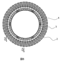
図6に、モータの中心軸を水平にしたときのステータ全体図を示す。本図においては上方は鉛直上方を意味している。本モータはアウターロータ型であり,図示されていないロータがステータの外周面に配置され,図示されていない固定支持部材に図示されていないベアリングを介してロータは回転自在に支持される。ロータの回転面は鉛直方向にあり,例えば,エレベータの巻上機のようにロープを上下方向に駆動する用途に適した配置となる。この図6に示した方向でモータが設置される場合では、重力により常にボビン2が固定子鉄心1から抜ける方向G1の力を受けるが、上述した構成によりボビン2が抜けるのを防止できる。よって,本実施形態はエレベータの巻上機としての用途に特に効果的である。この場合、回転子も複数に分割された回転子コアから構成され、かつ、前記回転子コアの内表面に磁石を配置する構成が好適である。
FIG. 6 shows an overall view of the stator when the central axis of the motor is horizontal. In the figure, the upper side means the vertical upper side. This motor is an outer rotor type. A rotor (not shown) is disposed on the outer peripheral surface of the stator, and the rotor is rotatably supported by a fixed support member (not shown) via a bearing (not shown). The rotor rotation surface is in the vertical direction, and is suitable for use in driving the rope in the vertical direction, such as an elevator hoist. When the motor is installed in the direction shown in FIG. 6, the force in the direction G1 in which the
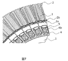
図7はステータ部の上方拡大斜視図であり、ボビンホルダ4の上部の形状を示す。図7において、固定子鉄心1を図示していないフレームに固定するためのボルト5が設けられ、さらにボビンホルダ4の上面にボルト5を覆うように絶縁用の防壁4bが設けられている。固定子鉄心1の鋼板の積層方向に貫通するボルトは、固定子鉄心1の上面から突出することになるが、この突出部(ヘッド)と巻線との接触を防壁4bによって回避することができる。したがって、防壁4bを採用し、また、ボビンホルダ4を絶縁材とすることにより、コイル足がボビンホルダ4の上部に配置するときにボルト5との干渉を防ぐことができ、絶縁距離を保つことが可能となる。
FIG. 7 is an enlarged perspective view of the upper portion of the stator portion and shows the shape of the upper portion of the
すなわち、既に述べたように、絶縁材2の上方側には延伸部2aが設けられており、固定子巻線3が巻き回される部分の内側にコイルガイド突起2bが設けられている。この構成によって、コイルの引き出し線を回転中心側に引き出すにあたって、導通部(ボルト5のヘッド部分)との接触を回避することができる。固定子巻線3のコイル端部は延伸部2aが設けられている側に引き出される構成としつつ、引き出し線が導通部分と接触しないようにコイルガイド突起2b及び防壁4bが設けられているということになる。
That is, as already described, the extending
図8は延伸部2aとボビンホルダ4を上方から覆うカバーが取り付けられた状態を示す斜視図である。図8のように、ボビンホルダ4の積厚方向上部にカバー6を設け、さらにカバー6と図示していないフレームとを空穴部6aにてボルト等で締結させる。カバー6を採用することにより、ボビンホルダ4を積厚方向上下から挟み込んで固定することができ、ボビンホルダが積厚方向上部に外れるのを防止することが可能となる。
FIG. 8 is a perspective view showing a state in which a cover that covers the extending
また、カバー6を採用することにより、防壁4bの間に配置されるコイル足がステータ端面から離れることを防止することが可能となる。当然,カバーを絶縁材で形成することによりコイル足の絶縁を施すこともできる。
Further, by employing the
1…固定子鉄心、1a…ティース部、2…絶縁材(ボビン)、2a…延伸部、2a’…T字の突起物、2b…コイルガイド突起、3…固定子巻線、4…ボビンホルダ、4a…突起物、4b…絶縁用の防壁、F1〜4…力がかかる方向、b…ティースに沿う方向、G1…重力の方向、5…ボルト、6…カバー、6a…空穴部。
DESCRIPTION OF
Claims (12)
前記絶縁材は、前記ティース部に挿入される方向に延伸する延伸部の先端に突起物を有し、
前記ボビンホルダは、前記固定子鉄心の一側端面に固定されるものであり、前記突起物と噛み合って前記絶縁材を前記固定子鉄心に固定することを特徴とする電動機。 A stator core having a plurality of teeth portions in the circumferential direction, a hollow insulating material that is wound around the stator winding and inserted into the teeth portions, and a plurality of the insulating materials fitted together to fix them. A bobbin holder that is fixed to the core,
The insulating material has a protrusion at the tip of the extending portion extending in the direction of insertion into the teeth portion,
The bobbin holder is fixed to one end face of the stator core, and meshes with the protrusions to fix the insulating material to the stator core .
前記固定子鉄心を前記一側端面から回転軸方向に貫通するボルトが、前記固定子鉄心の前記一側端面にヘッドが位置するように設けられ、
前記ボビンホルダは、前記ヘッドと、前記固定子巻線との接触を防ぐ防壁を有することを特徴とする請求項1又は2に記載の電動機。 The insulating material is inserted so that the extending portion is aligned with one side end surface of the stator core, and the extending portion is disposed on the one side end surface,
Bolts passing through the rotation axis direction of the stator core before Symbol one end face, the head is provided so as to be positioned on the one end face of the stator core,
The electric motor according to claim 1, wherein the bobbin holder has a barrier that prevents contact between the head and the stator winding.
前記絶縁材の前記ティース部に挿入される方向に延伸する延伸部の先端に設けられた突起物と噛み合う形状部分と、
前記ティース部への挿入方向の延長線上であって、前記形状部分を挟んで前記ティース部と反対方向に、前記固定子鉄心の一側端面とボルト固定するためのボルト穴とを有することを特徴とするボビンホルダ。 A bobbin holder in which a stator winding is wound and a hollow-shaped insulating material inserted into a tooth portion provided in a circumferential direction is fixed to a stator core,
A shape portion that meshes with a protrusion provided at the tip of an extending portion that extends in a direction to be inserted into the teeth portion of the insulating material;
A bolt hole for fixing a bolt to one side end face of the stator core is provided on an extension line in the insertion direction to the teeth portion and in a direction opposite to the teeth portion with the shape portion interposed therebetween. Bobbin holder.
Priority Applications (3)
| Application Number | Priority Date | Filing Date | Title |
|---|---|---|---|
| JP2011020294A JP5703045B2 (en) | 2011-02-02 | 2011-02-02 | Electric motor |
| CN201210022311.9A CN102629792B (en) | 2011-02-02 | 2012-02-01 | Electric motor |
| CN201510333264.3A CN104852497B (en) | 2011-02-02 | 2012-02-01 | Motor |
Applications Claiming Priority (1)
| Application Number | Priority Date | Filing Date | Title |
|---|---|---|---|
| JP2011020294A JP5703045B2 (en) | 2011-02-02 | 2011-02-02 | Electric motor |
Publications (3)
| Publication Number | Publication Date |
|---|---|
| JP2012161195A JP2012161195A (en) | 2012-08-23 |
| JP2012161195A5 JP2012161195A5 (en) | 2013-08-15 |
| JP5703045B2 true JP5703045B2 (en) | 2015-04-15 |
Family
ID=46587980
Family Applications (1)
| Application Number | Title | Priority Date | Filing Date |
|---|---|---|---|
| JP2011020294A Active JP5703045B2 (en) | 2011-02-02 | 2011-02-02 | Electric motor |
Country Status (2)
| Country | Link |
|---|---|
| JP (1) | JP5703045B2 (en) |
| CN (2) | CN104852497B (en) |
Families Citing this family (12)
| Publication number | Priority date | Publication date | Assignee | Title |
|---|---|---|---|---|
| JP5852513B2 (en) * | 2012-06-12 | 2016-02-03 | 株式会社日立産機システム | motor |
| CN103166338B (en) * | 2013-03-19 | 2015-07-08 | 杭州杰能动力有限公司 | Manufacturing method of switch reluctance (SR) external rotor motor |
| EP3079234B1 (en) | 2013-12-05 | 2019-07-31 | Hitachi Automotive Systems, Ltd. | Rotary electric machine |
| MY184839A (en) * | 2014-12-05 | 2021-04-26 | Mitsubishi Electric Corp | Motor stator and method of manufacturing motor stator |
| CN105990918B (en) * | 2015-02-11 | 2018-09-21 | 深圳市祥益节能科技有限公司 | motor and its stator |
| CN104702000A (en) * | 2015-02-28 | 2015-06-10 | 河北超亚电子科技股份有限公司 | Tiled stator core of motor |
| TWI558067B (en) | 2015-09-18 | 2016-11-11 | 財團法人工業技術研究院 | Winding frame structure for motors |
| CN105743238A (en) * | 2016-05-17 | 2016-07-06 | 珠海格力节能环保制冷技术研究中心有限公司 | Chain-type motor and iron core assembly thereof |
| CN106787523A (en) * | 2016-12-16 | 2017-05-31 | 江苏浩元动力科技有限公司 | A kind of electric machine winding skeleton structure and method for winding |
| JP6443958B1 (en) * | 2018-08-24 | 2018-12-26 | 株式会社e−Gle | Outer rotor type motor and electric vehicle |
| JP7211586B2 (en) * | 2018-09-28 | 2023-01-24 | 日本電産サーボ株式会社 | motor |
| KR102077600B1 (en) * | 2019-10-21 | 2020-02-17 | 엠토 주식회사 | A Ring Magnet Applied Type of a Rotor of a Motor for a Robot with a Eccentric Type of a Structure Having a Lower Cogging and a Lower Torque Ripple |
Family Cites Families (11)
| Publication number | Priority date | Publication date | Assignee | Title |
|---|---|---|---|---|
| JPS58112057U (en) * | 1982-01-25 | 1983-07-30 | 三菱電機株式会社 | Rotating electrical machine terminal block |
| JPS6046745A (en) * | 1983-08-22 | 1985-03-13 | Yaskawa Electric Mfg Co Ltd | Stator core of rotary electric machine |
| JP3337594B2 (en) * | 1995-07-18 | 2002-10-21 | ミネベア株式会社 | Stator structure of outer rotor type radial flat brushless DC motor and manufacturing method thereof |
| JP4774542B2 (en) * | 2001-07-25 | 2011-09-14 | 多摩川精機株式会社 | Motor stator structure |
| JP2003153509A (en) * | 2001-11-08 | 2003-05-23 | Matsushita Electric Ind Co Ltd | Motor |
| JP2003264945A (en) * | 2002-03-08 | 2003-09-19 | Tokushu Denso Kk | Rotary machine |
| JP2005323477A (en) * | 2004-05-11 | 2005-11-17 | Asmo Co Ltd | Motor |
| JP2006067650A (en) * | 2004-08-25 | 2006-03-09 | Fujitsu General Ltd | Axial gap motor |
| JP2009124921A (en) * | 2007-11-19 | 2009-06-04 | Mitsuba Corp | Electric motor |
| JP5190049B2 (en) * | 2009-12-11 | 2013-04-24 | 株式会社日立産機システム | External motor |
| JP2012016216A (en) * | 2010-07-02 | 2012-01-19 | Hitachi Industrial Equipment Systems Co Ltd | Rotation electrical machinery |
-
2011
- 2011-02-02 JP JP2011020294A patent/JP5703045B2/en active Active
-
2012
- 2012-02-01 CN CN201510333264.3A patent/CN104852497B/en active Active
- 2012-02-01 CN CN201210022311.9A patent/CN102629792B/en active Active
Also Published As
| Publication number | Publication date |
|---|---|
| CN104852497B (en) | 2016-09-07 |
| CN104852497A (en) | 2015-08-19 |
| CN102629792B (en) | 2015-07-22 |
| CN102629792A (en) | 2012-08-08 |
| JP2012161195A (en) | 2012-08-23 |
Similar Documents
| Publication | Publication Date | Title |
|---|---|---|
| JP5703045B2 (en) | Electric motor | |
| JP5711327B2 (en) | Transformer | |
| JP5927286B2 (en) | Rotating electric machine | |
| EP3166212A1 (en) | Motor | |
| WO2015050024A1 (en) | Motor and motor manufacturing method | |
| JP5659531B2 (en) | Armature and motor | |
| JP2011125159A (en) | Outer rotor motor | |
| JP2014073030A (en) | Armature and motor | |
| JP5873262B2 (en) | Outer rotor type motor | |
| KR101410491B1 (en) | Rotary machine | |
| JP6215034B2 (en) | Electric motor and electric motor bobbin | |
| EP3675326B1 (en) | Bobbin structure of armature | |
| JP2007325472A (en) | Motor | |
| JP2019030041A (en) | Rotary electric machine | |
| JP5621608B2 (en) | Outer rotor type motor | |
| EP3410576B1 (en) | Stator and motor | |
| JP2015211563A (en) | Stator of rotary electric machine and rotary electric machine including the same | |
| JP2020043677A (en) | Stator winding structure | |
| JP6097233B2 (en) | Concentrated winding permanent magnet motor, elevator hoisting machine using the same, and elevator | |
| EP3364527A1 (en) | Electric motor and blower | |
| JP4918279B2 (en) | Stator structure of rotating electrical machine | |
| JP5852513B2 (en) | motor | |
| JP5892886B2 (en) | Armature, armature manufacturing method, and rotating electric machine | |
| JP4234731B2 (en) | Lifting magnet | |
| KR200410748Y1 (en) | Rotor core structure of salient pole type generator |
Legal Events
| Date | Code | Title | Description |
|---|---|---|---|
| RD04 | Notification of resignation of power of attorney |
Free format text: JAPANESE INTERMEDIATE CODE: A7424 Effective date: 20120522 |
|
| A521 | Written amendment |
Free format text: JAPANESE INTERMEDIATE CODE: A523 Effective date: 20130628 |
|
| A621 | Written request for application examination |
Free format text: JAPANESE INTERMEDIATE CODE: A621 Effective date: 20130628 |
|
| A521 | Written amendment |
Free format text: JAPANESE INTERMEDIATE CODE: A523 Effective date: 20130628 |
|
| A977 | Report on retrieval |
Free format text: JAPANESE INTERMEDIATE CODE: A971007 Effective date: 20140723 |
|
| A131 | Notification of reasons for refusal |
Free format text: JAPANESE INTERMEDIATE CODE: A131 Effective date: 20140805 |
|
| A521 | Written amendment |
Free format text: JAPANESE INTERMEDIATE CODE: A523 Effective date: 20141006 |
|
| A521 | Written amendment |
Free format text: JAPANESE INTERMEDIATE CODE: A523 Effective date: 20141006 |
|
| A131 | Notification of reasons for refusal |
Free format text: JAPANESE INTERMEDIATE CODE: A131 Effective date: 20141118 |
|
| A521 | Written amendment |
Free format text: JAPANESE INTERMEDIATE CODE: A523 Effective date: 20141215 |
|
| TRDD | Decision of grant or rejection written | ||
| A01 | Written decision to grant a patent or to grant a registration (utility model) |
Free format text: JAPANESE INTERMEDIATE CODE: A01 Effective date: 20150127 |
|
| A61 | First payment of annual fees (during grant procedure) |
Free format text: JAPANESE INTERMEDIATE CODE: A61 Effective date: 20150223 |
|
| R150 | Certificate of patent or registration of utility model |
Ref document number: 5703045 Country of ref document: JP Free format text: JAPANESE INTERMEDIATE CODE: R150 |