EP1452892A1 - Phase difference layer laminate and method for production thereof - Google Patents
Phase difference layer laminate and method for production thereof Download PDFInfo
- Publication number
- EP1452892A1 EP1452892A1 EP02780035A EP02780035A EP1452892A1 EP 1452892 A1 EP1452892 A1 EP 1452892A1 EP 02780035 A EP02780035 A EP 02780035A EP 02780035 A EP02780035 A EP 02780035A EP 1452892 A1 EP1452892 A1 EP 1452892A1
- Authority
- EP
- European Patent Office
- Prior art keywords
- liquid crystal
- phase difference
- oriented
- difference layer
- laminated body
- Prior art date
- Legal status (The legal status is an assumption and is not a legal conclusion. Google has not performed a legal analysis and makes no representation as to the accuracy of the status listed.)
- Withdrawn
Links
Images



Classifications
-
- G—PHYSICS
- G02—OPTICS
- G02F—OPTICAL DEVICES OR ARRANGEMENTS FOR THE CONTROL OF LIGHT BY MODIFICATION OF THE OPTICAL PROPERTIES OF THE MEDIA OF THE ELEMENTS INVOLVED THEREIN; NON-LINEAR OPTICS; FREQUENCY-CHANGING OF LIGHT; OPTICAL LOGIC ELEMENTS; OPTICAL ANALOGUE/DIGITAL CONVERTERS
- G02F1/00—Devices or arrangements for the control of the intensity, colour, phase, polarisation or direction of light arriving from an independent light source, e.g. switching, gating or modulating; Non-linear optics
- G02F1/01—Devices or arrangements for the control of the intensity, colour, phase, polarisation or direction of light arriving from an independent light source, e.g. switching, gating or modulating; Non-linear optics for the control of the intensity, phase, polarisation or colour
- G02F1/13—Devices or arrangements for the control of the intensity, colour, phase, polarisation or direction of light arriving from an independent light source, e.g. switching, gating or modulating; Non-linear optics for the control of the intensity, phase, polarisation or colour based on liquid crystals, e.g. single liquid crystal display cells
- G02F1/133—Constructional arrangements; Operation of liquid crystal cells; Circuit arrangements
- G02F1/1333—Constructional arrangements; Manufacturing methods
- G02F1/1335—Structural association of cells with optical devices, e.g. polarisers or reflectors
- G02F1/13363—Birefringent elements, e.g. for optical compensation
-
- G—PHYSICS
- G02—OPTICS
- G02B—OPTICAL ELEMENTS, SYSTEMS OR APPARATUS
- G02B5/00—Optical elements other than lenses
- G02B5/30—Polarising elements
- G02B5/3016—Polarising elements involving passive liquid crystal elements
-
- G—PHYSICS
- G02—OPTICS
- G02B—OPTICAL ELEMENTS, SYSTEMS OR APPARATUS
- G02B5/00—Optical elements other than lenses
- G02B5/30—Polarising elements
- G02B5/3083—Birefringent or phase retarding elements
-
- G—PHYSICS
- G02—OPTICS
- G02F—OPTICAL DEVICES OR ARRANGEMENTS FOR THE CONTROL OF LIGHT BY MODIFICATION OF THE OPTICAL PROPERTIES OF THE MEDIA OF THE ELEMENTS INVOLVED THEREIN; NON-LINEAR OPTICS; FREQUENCY-CHANGING OF LIGHT; OPTICAL LOGIC ELEMENTS; OPTICAL ANALOGUE/DIGITAL CONVERTERS
- G02F1/00—Devices or arrangements for the control of the intensity, colour, phase, polarisation or direction of light arriving from an independent light source, e.g. switching, gating or modulating; Non-linear optics
- G02F1/01—Devices or arrangements for the control of the intensity, colour, phase, polarisation or direction of light arriving from an independent light source, e.g. switching, gating or modulating; Non-linear optics for the control of the intensity, phase, polarisation or colour
- G02F1/13—Devices or arrangements for the control of the intensity, colour, phase, polarisation or direction of light arriving from an independent light source, e.g. switching, gating or modulating; Non-linear optics for the control of the intensity, phase, polarisation or colour based on liquid crystals, e.g. single liquid crystal display cells
- G02F1/133—Constructional arrangements; Operation of liquid crystal cells; Circuit arrangements
- G02F1/1333—Constructional arrangements; Manufacturing methods
- G02F1/1335—Structural association of cells with optical devices, e.g. polarisers or reflectors
- G02F1/13363—Birefringent elements, e.g. for optical compensation
- G02F1/133631—Birefringent elements, e.g. for optical compensation with a spatial distribution of the retardation value
-
- G—PHYSICS
- G02—OPTICS
- G02F—OPTICAL DEVICES OR ARRANGEMENTS FOR THE CONTROL OF LIGHT BY MODIFICATION OF THE OPTICAL PROPERTIES OF THE MEDIA OF THE ELEMENTS INVOLVED THEREIN; NON-LINEAR OPTICS; FREQUENCY-CHANGING OF LIGHT; OPTICAL LOGIC ELEMENTS; OPTICAL ANALOGUE/DIGITAL CONVERTERS
- G02F1/00—Devices or arrangements for the control of the intensity, colour, phase, polarisation or direction of light arriving from an independent light source, e.g. switching, gating or modulating; Non-linear optics
- G02F1/01—Devices or arrangements for the control of the intensity, colour, phase, polarisation or direction of light arriving from an independent light source, e.g. switching, gating or modulating; Non-linear optics for the control of the intensity, phase, polarisation or colour
- G02F1/13—Devices or arrangements for the control of the intensity, colour, phase, polarisation or direction of light arriving from an independent light source, e.g. switching, gating or modulating; Non-linear optics for the control of the intensity, phase, polarisation or colour based on liquid crystals, e.g. single liquid crystal display cells
- G02F1/133—Constructional arrangements; Operation of liquid crystal cells; Circuit arrangements
- G02F1/1333—Constructional arrangements; Manufacturing methods
- G02F1/1335—Structural association of cells with optical devices, e.g. polarisers or reflectors
- G02F1/13363—Birefringent elements, e.g. for optical compensation
- G02F1/133633—Birefringent elements, e.g. for optical compensation using mesogenic materials
-
- G—PHYSICS
- G02—OPTICS
- G02F—OPTICAL DEVICES OR ARRANGEMENTS FOR THE CONTROL OF LIGHT BY MODIFICATION OF THE OPTICAL PROPERTIES OF THE MEDIA OF THE ELEMENTS INVOLVED THEREIN; NON-LINEAR OPTICS; FREQUENCY-CHANGING OF LIGHT; OPTICAL LOGIC ELEMENTS; OPTICAL ANALOGUE/DIGITAL CONVERTERS
- G02F1/00—Devices or arrangements for the control of the intensity, colour, phase, polarisation or direction of light arriving from an independent light source, e.g. switching, gating or modulating; Non-linear optics
- G02F1/01—Devices or arrangements for the control of the intensity, colour, phase, polarisation or direction of light arriving from an independent light source, e.g. switching, gating or modulating; Non-linear optics for the control of the intensity, phase, polarisation or colour
- G02F1/13—Devices or arrangements for the control of the intensity, colour, phase, polarisation or direction of light arriving from an independent light source, e.g. switching, gating or modulating; Non-linear optics for the control of the intensity, phase, polarisation or colour based on liquid crystals, e.g. single liquid crystal display cells
- G02F1/133—Constructional arrangements; Operation of liquid crystal cells; Circuit arrangements
- G02F1/1333—Constructional arrangements; Manufacturing methods
- G02F1/1335—Structural association of cells with optical devices, e.g. polarisers or reflectors
- G02F1/13363—Birefringent elements, e.g. for optical compensation
- G02F1/133638—Waveplates, i.e. plates with a retardation value of lambda/n
-
- G—PHYSICS
- G02—OPTICS
- G02F—OPTICAL DEVICES OR ARRANGEMENTS FOR THE CONTROL OF LIGHT BY MODIFICATION OF THE OPTICAL PROPERTIES OF THE MEDIA OF THE ELEMENTS INVOLVED THEREIN; NON-LINEAR OPTICS; FREQUENCY-CHANGING OF LIGHT; OPTICAL LOGIC ELEMENTS; OPTICAL ANALOGUE/DIGITAL CONVERTERS
- G02F1/00—Devices or arrangements for the control of the intensity, colour, phase, polarisation or direction of light arriving from an independent light source, e.g. switching, gating or modulating; Non-linear optics
- G02F1/01—Devices or arrangements for the control of the intensity, colour, phase, polarisation or direction of light arriving from an independent light source, e.g. switching, gating or modulating; Non-linear optics for the control of the intensity, phase, polarisation or colour
- G02F1/13—Devices or arrangements for the control of the intensity, colour, phase, polarisation or direction of light arriving from an independent light source, e.g. switching, gating or modulating; Non-linear optics for the control of the intensity, phase, polarisation or colour based on liquid crystals, e.g. single liquid crystal display cells
- G02F1/137—Devices or arrangements for the control of the intensity, colour, phase, polarisation or direction of light arriving from an independent light source, e.g. switching, gating or modulating; Non-linear optics for the control of the intensity, phase, polarisation or colour based on liquid crystals, e.g. single liquid crystal display cells characterised by the electro-optical or magneto-optical effect, e.g. field-induced phase transition, orientation effect, guest-host interaction or dynamic scattering
- G02F1/139—Devices or arrangements for the control of the intensity, colour, phase, polarisation or direction of light arriving from an independent light source, e.g. switching, gating or modulating; Non-linear optics for the control of the intensity, phase, polarisation or colour based on liquid crystals, e.g. single liquid crystal display cells characterised by the electro-optical or magneto-optical effect, e.g. field-induced phase transition, orientation effect, guest-host interaction or dynamic scattering based on orientation effects in which the liquid crystal remains transparent
- G02F1/1393—Devices or arrangements for the control of the intensity, colour, phase, polarisation or direction of light arriving from an independent light source, e.g. switching, gating or modulating; Non-linear optics for the control of the intensity, phase, polarisation or colour based on liquid crystals, e.g. single liquid crystal display cells characterised by the electro-optical or magneto-optical effect, e.g. field-induced phase transition, orientation effect, guest-host interaction or dynamic scattering based on orientation effects in which the liquid crystal remains transparent the birefringence of the liquid crystal being electrically controlled, e.g. ECB-, DAP-, HAN-, PI-LC cells
Definitions
- the present invention relates to a phase difference layer laminated body which offers high orientation freedom and allows easy patterning, a manufacturing method thereof, and a liquid crystal display device.
- Phase difference film used for liquid crystal displays and the like is conventionally made of a polymer film which is stretched in certain directions to orient the main chains of the polymer in these directions so that the polymer film exhibits refractive index anisotropy.
- the polymer film can be provided with refractive index anisotropy with relative ease; the method was excellent in that it enabled easy formation of phase difference films.
- phase difference films having vertical polymer orientation relative to the surface, or various other orientation directions are now in demand; the problem with the above method for obtaining phase difference films by stretching polymer films is that it cannot meet such demand because of its little freedom in setting orientation direction.
- the present invention has been devised in view of the above problems, and a main object thereof is to provide a phase difference layer laminated body which has very high freedom of molecular orientation in its phase difference layer and which can be manufactured with ease, a manufacturing method thereof, and a liquid crystal display device.
- the present invention provides, as set forth in claim 1, a phase difference layer laminated body including a base material having orientability, and a phase difference layer made of a liquid crystal material that can form a nematic phase and formed in a pattern on the base material such as to have refractive index anisotropy.
- a liquid crystal material that can form a nematic phase is used for the phase difference layer, by suitably selecting the type of liquid crystal material and the base material having orientability, it is possible to determine orientation directions with ease, and therefore the phase difference layer laminated body thus obtained can be applied to various optical elements.
- the above liquid crystal material that can form a nematic phase is obtained by polymerization of at least one of a polymerizable liquid crystal monomer, a polymerizable liquid crystal oligomer, and a polymerizable liquid crystal polymer, as set forth in claim 2.
- a polymerizable liquid crystal material allows easy patterning of the phase difference layer and enables highly precise patterning, which is achieved, in a curing step, by irradiating the material with an activating radiation beam for polymerizing the polymerizable liquid crystal material in a certain pattern, followed by development.
- the above liquid crystal material that can form a nematic phase is obtained by polymerization of a polymerizable liquid crystal monomer, as set forth in claim 3. This is because polymerizable liquid crystal monomer can be handled most easily among the polymerizable liquid crystal materials noted above, and therefore it allows relatively easy fabrication of the phase difference layer laminated body.
- the above base material having orientability may be obtained by forming an oriented film on a transparent substrate, as set forth in claim 4. This is because the configuration in which a separate oriented film is provided increases the freedom of orientation direction to a very high degree.
- the above oriented film may be formed in a pattern with portions that are oriented in at least two different directions, the liquid crystal material on the oriented film having refractive index anisotropy conforming to the plurality of orientation directions of this oriented film.
- phase difference portions respectively oriented in different directions can be formed in the same phase difference layer, and therefore it will find various optical applications.
- the above base material having orientability may be a stretched film, as set forth in claim 6.
- the use of a stretched film for the base material having orientability facilitates the formation of the base material, offering the merit of simplicity of the processing step.
- the present invention provides, as set forth in claim 7, a method for manufacturing a phase difference layer laminated body, the method including:
- the refractive index anisotropic material and orientation processing method by suitably selecting the refractive index anisotropic material and orientation processing method, it is possible to determine the orientation directions of the refractive index anisotropic material with relative ease, whereby the freedom in design of the resultant phase difference layer laminated body can be much improved.
- the base material is a base material having orientability
- the refractive index anisotropic material is a liquid crystal material that can form a nematic phase
- the orientation processing step is a step of maintaining the refractive index anisotropic material layer in a temperature at which the liquid crystal material transforms into a liquid crystal phase, as set forth in claim 8.
- the orientation processing can be achieved with ease simply by maintaining the liquid crystal material on the base material having orientability in a temperature at which the liquid crystal material transforms into a liquid crystal phase, and by suitably selecting the base material having orientability and liquid crystal material, a phase difference layer laminated body having a very high freedom of orientation direction can be obtained.
- the above liquid crystal material is a material having at least one of a polymerizable liquid crystal monomer, a polymerizable liquid crystal oligomer, and a polymerizable liquid crystal polymer
- the above orientation fixing step is a step of irradiating, with an activating radiation beam, the material having at least one of the polymerizable liquid crystal monomer, the polymerizable liquid crystal oligomer, and the polymerizable liquid crystal polymer for polymerization thereof, as set forth in claim 9.
- the use of the polymerizable liquid crystal material as a liquid crystal material has the merit that it enables highly precise patterning of the phase difference layer, which is achieved by irradiating the material with an activating radiation beam in a pattern in the orientation fixing step, followed by a development step.
- the above liquid crystal material is a polymerizable liquid crystal monomer, as set forth in claim 10. This is because the polymerizable liquid crystal monomer is most favorable in terms of handling among other polymerizable liquid crystal materials.
- the above activating radiation beam irradiation step may be a step of irradiating the material with the activating radiation beam in a pattern
- the method may further include a development step of developing unpolymerized portions of the liquid crystal material, after the above step of irradiating the material with the activating radiation beam in the pattern, as set forth in claim 11.
- the above base material having orientability is obtained by forming an oriented film on a transparent substrate, as set forth in claim 12.
- the liquid crystal material can be oriented in various different directions by suitably selecting the type of oriented film, whereby the freedom in design of the phase difference layer laminated body can be much improved.
- the above oriented film is formed in a pattern with portions that are oriented in at least two different directions, the liquid crystal material on the oriented film having refractive index anisotropy conforming to the plurality of orientation directions of the oriented film, as set forth in claim 13.
- the single phase difference layer can have portions therein that are oriented in different directions. The merit is therefore the phase difference layer laminated body thus obtained can be used to various optical applications.
- the above base material having orientability may be a stretched film, as set forth in claim 14.
- an oriented film need not be formed on the base material, and a base material having orientability can readily be processed in the production step, and also the cost of the resultant phase difference layer laminated body can be lowered.
- the present invention further provides, as set forth in claim 15, a liquid crystal display device that uses the phase difference layer laminated body according to any of claims 1 to 6.
- the liquid crystal display device of the invention will be of high quality because of the use of the above phase difference layer laminated body.
- a liquid crystal display device comprising: a liquid crystal display element including a liquid crystal layer and comprising a plurality of unit cells that constitute a multiplicity of pixels, liquid crystal molecules on a surface of the liquid crystal layer being orientable in directions of a plurality of different directors within each of the unit cells; and a phase difference optical element arranged at least on one side in a thickness direction of the liquid crystal display element, the phase difference optical element being divided into a plurality of oriented compensation regions in accordance with the directions of the directors for the liquid crystal molecules in the each unit cell, liquid crystal substance being oriented and fixed in each of the oriented compensation regions.
- this liquid crystal display device is capable of precise optical compensation, improves the problem of visual dependency, and realizes high quality image display.
- the each unit cell of the liquid crystal display element may be divided into a plurality of oriented display regions, the liquid crystal molecules on the surface of the liquid crystal layer being oriented in different directions of directors for each of the oriented display regions, and the oriented compensation regions of the phase difference optical element may be formed corresponding to the oriented display regions, as set forth in claim 17.
- a plurality of the oriented compensation region may be formed in the phase difference optical element relative to one oriented display region of the unit cell, as set forth in claim 18. Thereby, even more precise optical compensation can be achieved.
- the oriented display regions of the liquid crystal display element may be formed in such a manner as to divide each unit cell into four or more sections with an equal angular spacing around a center of said each unit cell, as set forth in claim 19.
- the liquid crystal molecules on the surface of the liquid crystal layer of the liquid crystal display element may be oriented with the directors in symmetric directions relative to respective centers of the unit cells, as set forth in claim 20.
- the oriented compensation regions of the phase difference optical element may be formed in such a manner as to divide each unit cell into four or more sections with an equal angular spacing around a center of the each unit cell, as set forth in claim 21.
- liquid crystal molecules in the liquid crystal display element are oriented in four directions, for example, with the molecules in the phase difference layer being respectively oriented in a favorable manner for each orientation direction, the viewing-angle dependency is lowered and high display quality is achieved.
- a pair of 180° opposite oriented compensation regions relative to the center of the each unit cell of the phase difference optical element may be oriented in the same direction, as set forth in claim 22.
- the liquid crystal display element may be driven by a method of any of TN (Twisted Nematic) type, STN (Super Twisted Nematic) type, VA (Vertically Alignment) type, MVA (Multi-domain Vertically Alignment) type, PVA (Patterned Vertically Alignment) type, IPS (In-plane Switching) type, OCB (Optically Compensated Birefringence) type, and ECB (Electrically Controlled Birefringence) type, as set forth in claim 23.
- TN Transmission Nematic
- STN Super Twisted Nematic
- VA Very Alignment
- MVA Multi-domain Vertically Alignment
- PVA Powerned Vertically Alignment
- IPS In-plane Switching
- OCB Optically Compensated Birefringence
- ECB Electrodefringence
- phase difference layer laminated body according to any of claims 1 to 6 may be used for the above phase difference optical element, as set forth in claim 24.
- phase difference layer laminated body and the manufacturing method thereof, according to the invention, will be hereinafter described respectively.
- the phase difference layer laminated body of the invention is characterized by having a base material having orientability, and a phase difference layer made of a liquid crystal material that can form a nematic phase and formed on the base material such as to have refractive index anisotropy.
- phase difference layer laminated body of the invention With such a construction of the phase difference layer laminated body of the invention, if the orientability of the base material is such that it can orient liquid crystal at a preset angle relative to the phase difference layer surface, and a phase difference layer laminated body is formed with the use of liquid crystal material that is orientable in such a manner, a phase difference layer oriented at a preset angle to the surface can readily be provided.
- a phase difference layer laminated body having such a phase difference layer will find new applications in addition to the conventional ones.
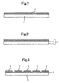
- Fig. 1 shows one example of a phase difference layer laminated body of the invention, in a state in which a phase difference layer 2 of liquid crystal material that can form a nematic phase is formed on a base material 1 having surface orientability such that the liquid crystal has refractive index anisotropy.
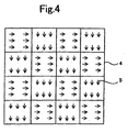
- the invention includes another construction such as the one shown in Fig. 2 wherein the base material 1 having the above orientability is constituted by a transparent substrate 3 and an oriented film 4 formed thereon.
- the use of such an oriented film 4 will make the orientation freedom of the phase difference layer 2 extremely high as will be described later, which in turn enhances the orientation freedom of the phase difference layer laminated body to a very high degree.
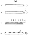
- the phase difference layer formed on the orientated film 4 may have a certain pattern as shown in Fig. 3.
- a three-dimensional display device or the like for example, which enables display of three-dimensional images by differing the polarization for the left and right eyes, requires a phase difference layer laminated body having a patterned phase difference layer; the phase difference layer laminated body shown in Fig. 3 can be used in such a three-dimensional display device or the like.
- phase difference layer laminated body of the invention Various elements of the phase difference layer laminated body of the invention are described below in more detail.
- the phase difference layer laminated body of the invention is characterized in that a phase difference layer 2 of a liquid crystal material that can form a nematic phase is formed on a base material 1 having orientability such that the liquid crystal has refractive index anisotropy, as shown in Fig. 1.
- liquid crystal material for the material forming the phase difference layer, a liquid crystal material is used as noted above.
- liquid crystal material in this invention refers to a material that can transform into a liquid crystal phase at a certain temperature; more particularly, this invention is characterized in that this liquid crystal phase of the material is a nematic phase.
- a liquid crystal material is transformed into a liquid crystal phase upon a base material having orientability, whereby the liquid crystal molecules in the phase difference layer are oriented to exhibit refractive index anisotropy. Therefore, the upper limit of the above-mentioned temperature should not be limited to a specific value and may be set such that no damage is inflicted on the base material, or, in the case of an oriented film formed on a transparent substrate as will be described later, on the transparent substrate and oriented film. More specifically, a liquid crystal material that transforms into a liquid crystal phase at a temperature of 120°C or lower, more preferably 100°C or lower, can favorably be used in respect of easy control of processing temperature and maintenance of dimensional precision.
- the lower limit, on the other hand, of the temperature at which the liquid crystal phase forms, should be set so that the liquid crystal material can maintain its orientation, subject to the temperature range for the application as a phase difference layer laminated body.
- a liquid crystal material in an application as a phase difference layer laminated body can take two different states:
- both a non-polymerizable polymer liquid crystal material and a polymerizable liquid crystal material can be used as will be described later.
- a polymerizable liquid crystal material when forming the phase difference layer, as will be described in more detail under the section of "manufacturing method of phase difference layer laminated body," polymerization is achieved by irradiating the material with the activating radiation beam. In this case, therefore, the liquid crystal material used in the phase difference layer laminated body has already been polymerized, its orientation being fixed. Namely, in the case of the polymerizable liquid crystal material, there is no limitation on the lower limit of the temperature at which the material transforms into a liquid crystal phase.
- the liquid crystal phase is in the glass state when used as the phase difference layer laminated body. That is, if it transforms into an isotropic state due to a rise in temperature during storage or use, its orientation will be in disorder and the phase difference layer can no longer be put in use.
- the material transform into an isotropic phase at temperatures equal to or more than a preset value.
- the lower limit of the temperature at which the material transforms into an isotropic phase in this case depends on the purposes of use, but generally speaking, it is at least 80°C, or more preferably, 100°C or more.
- the liquid crystal material that can form a nematic phase used in this invention can either be a polymerizable liquid crystal material and non-polymerizable polymer liquid crystal material as noted above.
- any of polymerizable liquid crystal monomer, polymerizable liquid crystal oligomer, and polymerizable liquid crystal polymer may be used.
- a liquid crystal material having a relatively high isotropic transition temperature should preferably be used.
- a polymerizable liquid crystal material is most preferably used. This is because the use of polymerizable liquid crystal material, whose orientation can be fixed by polymerization that is achieved by irradiating the material with the activating radiation beam as will be described later, enables easy orientation of the liquid crystal at low temperatures, and also because it can be used without temperature limitations or other restrictions due to the fixed orientation when put in use.
- a polymerizable liquid crystal monomer is preferably used in this invention. This is because a polymerizable liquid crystal monomer lets itself to be oriented at a lower temperature than other polymerizable liquid crystal materials such as polymerizable liquid crystal oligomers or polymers; it also has high orientation sensitivity, allowing the orientation to be readily achieved.
- the compounds included in the general formula 1 below or a mixture of two or more of the following compounds may be used.
- X is preferably an integer of 2 to 5.
- polymerizable liquid crystal oligomers or polymers can also be used in this invention. Any one of known polymerizable liquid crystal oligomers or polymers may suitably be selected and used.
- Photopolymerization initiators may be used as required in this invention.
- Photopolymerization initiator may not always be necessary as with the case with, for example, polymerization of polymerizable liquid crystal material by irradiation of electron beams, but it is normally used for the promotion of polymerization in the commonly used method of curing by irradiation of, e.g., ultraviolet rays.
- a sensitizing agent may be added in addition to the photopolymerization initiator, in an amount that does not inhibit achievement of the object of the invention.
- Photopolymerization initiator is generally added in a range of 0.01 to 20 % by weight; preferably, it is added in a range of 0.1 to 10 % by weight, and more preferably 0.5 to 5 % by weight, to the polymerizable liquid crystal material of the invention.
- non-polymerizable liquid crystal materials can also be used in this invention, as noted above.
- Any such liquid crystal material can be used as long as it satisfies the requirement that the orientation of liquid crystal does not change during the use or storage thereof as a phase difference layer laminated body as described above; generally, however, polymer material is preferable in terms of the temperatures at which the polymer material transforms into a liquid phase or a liquid crystal phase.
- Any commonly used liquid crystal material that can form a nematic phase in a liquid crystal phase can be used, including both main-chain and side-chain liquid crystal polymers.
- main-chain liquid crystal polymers are polymers such as polyesters, polyamides, polycarbonates, and polyesterimides.
- side-chain liquid crystal polymers are those that have a backbone structure such as polyacrylate, polymethacrylate, polysiloxane, and polymalonate and a low molecular weight liquid crystal compound (mesogen group) comprising a para-substituted cyclic compound or the like as a side chain, with or without a spacer comprising conjugated atoms.
- a backbone structure such as polyacrylate, polymethacrylate, polysiloxane, and polymalonate
- a low molecular weight liquid crystal compound (mesogen group) comprising a para-substituted cyclic compound or the like as a side chain, with or without a spacer comprising conjugated atoms.
- the above-mentioned material must be formed into a phase difference layer having refractive index anisotropy.
- Refractive index anisotropy differs depending on the liquid crystal material being used and the orientability of the base material surface, but the following can generally be said:
- the phase difference layer formed of the above-mentioned liquid crystal material may have a certain pattern.
- a phase difference layer laminated body having a patterned phase difference layer is preferably used in, for example, a three-dimensional liquid crystal display device or the like, wherein unit cells are divided into groups for left and right eyes, which are given different degrees of polarization, thereby creating a three-dimensional image.
- a patterned phase difference layer laminated body was conventionally made by manual cutting and bonding of phase difference layer films comprising common stretched films. Such technique was problematic in terms of cost and had limitations on the formation of highly precise patterns.
- the present invention overcomes this problem and provides a phase difference layer laminated body in which a phase difference layer is formed on the base material in a highly precise pattern.
- the pattern formation method differs depending on the type of liquid crystal material. That is, the pattern formation method for a polymerizable liquid crystal material is different from that for a normal liquid crystal material.
- phase difference layer laminated body in the case of the polymerizable liquid crystal material, the irradiation of activating radiation beam for the fixing of the orientation of liquid crystal material is made in a certain pattern, and after the polymerization, uncured portions of liquid crystal material are removed by a solvent; patterning of the phase difference layer is thus readily achieved.
- a polymerizable liquid crystal monomer is preferably used because of the ease of the patterning. With a polymerizable liquid crystal monomer, development is easy, the pattern is more clear-cut, and formation of more precise pattern is possible.
- a photolithography technique using a photoresist or a method of applying a normal liquid crystal material in a certain pattern by a nozzle discharge or printing technique may be adopted for the pattern formation method in the case of using a non-polymerizable polymer liquid crystal material.
- the pattern may be any pattern, for example, striped or zigzagged.
- the phase difference layer laminated body of the invention is comprised of a base material 1 having orientability, on which is formed the above-described phase difference layer 2, as shown in Fig. 1.
- the base material having orientability there are two cases: One is that the base material 1 itself has orientability, as shown in Fig. 1, and the other is that an oriented film 4 is formed on a transparent substrate 3 as shown in Fig. 2 so that they together function as a base material 1 having orientability.
- the followings are descriptions of these cases as the first and second embodiments.
- the base material itself has orientability; specifically, the base material is a stretched film.
- the base material is a stretched film.
- the liquid crystal material can be oriented along a stretched direction of the film. Therefore, the processing of the base material is accomplished simply by preparation of a stretched film, which is a merit that the processing step is made very simple.
- any commercially available stretched film can be used, or a stretched film can be made, according to needs, of various materials.
- examples of the film include films made of thermoplastic polymers, such as polycarbonate polymers, polyester polymers such as polyarylate or polyethylene terephthalate, polyimide polymers, polysulfone polymers, polyethersulfon polymers, polystyrene polymers, polyolefin polymers such as polyethylene or polypropylene, polyvinyl alcohol polymers, cellulose acetate polymers, polyvinyl chloride polymers, and polymethylmethacrylate polymers, and films made of liquid crystal polymers.
- thermoplastic polymers such as polycarbonate polymers, polyester polymers such as polyarylate or polyethylene terephthalate, polyimide polymers, polysulfone polymers, polyethersulfon polymers, polystyrene polymers, polyolefin polymers such as polyethylene or polypropylene, polyvinyl alcohol polymers, cellulose acetate polymers, polyvinyl chloride polymers, and polymethylmethacrylate polymers, and films made of liquid crystal polymers
- PET polyethylene terephthalate
- the stretch ratio of the stretched film used in this invention is not limited to a particular value, as long as the film exhibits orientability. Thus, even a biaxially stretched film can be used, if the stretch ratio differs between the two axes.
- the stretch ratio differs largely depending on the material used, and there are no particular limits to the stretch ratio. Generally, materials having a 150 to 300% stretch ratio can be used; a preferable range is 200 to 250%.
- the base material having the above orientability comprises a transparent substrate and an oriented film formed thereon.
- An oriented film commonly used for a liquid crystal display device or the like can favorably be used for the oriented film of this embodiment; generally, an oriented film of polyimide that has undergone rubbing treatment is favorably used.
- any transparent material can be used, e.g., a transparent and rigid material having no flexibility such as silica glass, Pyrex (registered trademark) glass, and synthetic silica glass, or a transparent and flexible material such as a transparent resin film, and optical resin sheet or the like.
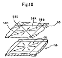
- the above oriented film may have a certain pattern on the surface thereof. That is, the oriented film may have a pattern with different directions of orientation, including portions oriented in, at least two, different directions.
- Fig. 4 is a model view showing an oriented film 4 formed with a pattern of different directions of orientation. Arrows 5 in the drawing indicate the directions of orientation.
- Fig. 4 shows one example in which the oriented film has a checked pattern, but various other patterns e.g., a striped pattern and the like, may be employed in accordance with the purposes of use in this invention.
- the phase difference layer comprising a liquid crystal material having refractive index anisotropy provided thereon can have a pattern of refractive index anisotropy conforming to the pattern on the oriented film surface.
- a phase difference layer laminated body having portions with different phase differences in a certain pattern can be obtained, which can be used in various applications.
- Patterning on the oriented film surface may be achieved by a rubbing technique using a mask, or in the case of using a film oriented with the irradiation of light beams, by a mask exposure technique or the like.
- phase difference layer laminated body of the invention can be formed with other functional layers such as a protective layer or the like in accordance with the purposes for which the optical element is to be used.
- phase difference layer laminated body of the invention is used as a ⁇ /4 phase difference layer, it can be used as a circular polarization plate by bonding a polarization plate thereto with an adhesive layer interposed therebetween.
- phase difference layers can be laminated.
- the second phase difference layer is formed after the formation of an oriented film and rubbing treatment thereof on the first phase difference layer.
- the oriented film may be a photo-oriented film instead.
- Fig. 6 shows an example in which a ⁇ /2 phase difference layer 13 is formed on a glass substrate 11 with an oriented film 12 interposed therebetween, and a ⁇ /4 phase difference layer 14 is further formed thereon with another oriented film 12 interposed therebetween.
- Fig. 7 shows an example in which a ⁇ /4 phase difference layer 14 is formed on a glass substrate 11 with an oriented film interposed therebetween, and a ⁇ /2 phase difference layer 13 is further formed thereon with another oriented film 12 interposed therebetween.
- the phase difference layer laminated body can function as a broadband phase difference plate shown, for example, in Japanese Patent Laid-Open Publication No. Hei 10-68816. Furthermore, by attaching a polarization plate on the opposite surface of the glass substrate 11 with an adhesive layer 15 interposed therebetween as shown in Fig. 6, it can function as a broadband circular polarization plate, with a non-polarized beam incident from the side of the polarization plate.
- the two oriented films should be inclined to each other approximately at 60° (60 ⁇ 10°). This can be achieved by, for example, changing the direction of rubbing, or the like.
- a method for manufacturing phase difference layer laminated body according to the invention is characterized by having:
- the orientation direction can be determined relatively freely in the orientation processing step, thus offering an advantage that phase difference layers of various different directions of fast axis (or slow axis) can be formed.
- Fig. 5 shows one example of the method for manufacturing phase difference layers according to the invention.
- a base material 1 is first prepared, which includes a transparent substrate 3 on which is formed an oriented film 4, as shown in Fig. 5(a) (base material preparation step).
- a refractive index anisotropic material layer 6 comprising a polymerizable liquid crystal material is formed on this base material 1 (application step). This is then let stand under a preset temperature for orienting the polymerizable liquid crystal material along the direction of orientation of the oriented film (orientation processing step).
- an activating radiation beam 8 such as ultraviolet light or the like is irradiated, so that energy-radiated portions of the polymerizable liquid crystal material are cured in a certain pattern (as shown in Fig. 5(c), orientation fixing step), and lastly, it is developed using a solvent for forming the phase difference layer 2 in the certain pattern; a phase difference layer laminated body having a phase difference layer 2 in a pattern on a base material 1 is thus obtained.
- the first step of the phase difference layer laminated body manufacturing method of the invention is the base material preparation step of preparing a base material.
- the refractive index anisotropic material having an ability of providing refractive index anisotropy is a liquid crystal material and if the orienting method in the orientation processing step uses a base material having orientability, then it is necessary to prepare a base material having orientability. On the other hand, if another method is to be used for the orientation, then the base material need not have orientability.
- Base materials having orientability will not be described here since they have already been described under the section "2.
- Base material having orientability in "A. Phase difference layer laminated body” in the foregoing.
- substrates in the case where no such orientability is required may suitably be selected in accordance with the purposes of use; since transparency is usually a requirement, a transparent and rigid material having no flexibility such as silica glass, Pyrex (registered trademark) glass, and synthetic silica glass, or a transparent and flexible material such as a transparent resin film, and optical resin sheet, or the like may be used, for example.
- a transparent and rigid material having no flexibility such as silica glass, Pyrex (registered trademark) glass, and synthetic silica glass, or a transparent and flexible material such as a transparent resin film, and optical resin sheet, or the like may be used, for example.
- the next step is the application step of applying a refractive index anisotropic material having an ability of providing refractive index anisotropy on the base material.
- the first example of the refractive index anisotropic material having an ability of providing refractive index anisotropy on the base material used in this invention is a liquid crystal material.
- the liquid crystal material is not described here since it has already been described under the section "1.
- a photopolymerization initiator may be used as required, for instance in the case of UV curing.
- Specific examples of such a photopolymerization initiator are Irg 369, Irg 907, Irg 184 (trade name) and the like, manufactured by Ciba Specialty Chemicals Corp.
- Refractive index anisotropic materials other than liquid crystal materials include materials that form layers and exhibit refractive index anisotropy when the molecules are more or less oriented in certain directions. Any materials that can usually be made to function as a phase difference layer by stretching may be used: Such materials include thermoplastic polymers such as polycarbonate polymers, polyester polymers such as polyarylate or polyethylene terephthalate, polyimide polymers, polysulfone polymers, polyethersulfon polymers, polystyrene polymers, polyolefin polymers such as polyethylene or polypropylene, polyvinyl alcohol polymers, cellulose acetate polymers, polyvinyl chloride polymers, and polymethylmethacrylate polymers.
- thermoplastic polymers such as polycarbonate polymers, polyester polymers such as polyarylate or polyethylene terephthalate, polyimide polymers, polysulfone polymers, polyethersulfon polymers, polystyrene polymers, polyolefin polymers such as polyethylene
- a refractive index anisotropic material that has relatively high polarity is preferable so that it can be oriented by applying a high electric or magnetic field in the orientation processing step to be described later for performing orientation processing.
- a specific example is a side-chain modified phonoxy resin into which 4-nitrophenyl carbamate is introduced.
- the above material is dissolved in a solvent or the like to form an application liquid, which is applied using various application methods such as spin coating, casting, dipping, bar coating, blade coating, roll coating, spray coating, and the like.
- a refractive index anisotropic material that melts and liquefies at a temperature at which the material itself does not decompose or inflict damage on the base material, can be applied in a heated state without solvent. Same application methods as listed above can be used in this case, too.
- the more preferable method for the ease of handling is the method of dissolving the above-mentioned material in a solvent and applying the same. Because a polymerizable liquid crystal material is favorably used in this invention as noted above, it is particularly preferable to use a solution of this material as the application liquid.
- any solvents in which the above polymerizable liquid crystal material or the like can be dissolved, and which do not inhibit the orientability of the base material, may be used for this purpose.
- solvents include hydrocarbons such as benzene, toluene, xylene, n-butylbenzene, diethylbenzene, and tetralin, ethers such as metoxybenzene, 1,2-dimetoxybenzene, and diethylene glycol dimethylether, ketones such as acetone, methylethylketone, methylisobutylketone, cyclohexanone, and 2,4-pentanedion, esters such as ethyl acetate, ethylene glycol monomethyl ether acetate, propylene glycol monomethyl ether acetate, propylene glycol monoethyl ether acetate, and ⁇ -butyrolactone, amide solvents such as 2-pyrrolidone, N-methyl-2-pyrrolidone, dimethyl formamide, and dimethylacetamide, halogenated solvents such as chloroform, dichloromethane, carbon tetrachloride
- the solubility of the polymerizable liquid crystal material or the like may not be sufficient, or the above substrate having orientability may be corroded with the use of a single type of solvent. Such troubles can be avoided by using a mixture of two or more types of solvents.
- solvents hydrocarbon solvents and glycol mono ether acetate solvents are favorably used alone, while ethers and ketones are favorably used in mixture with glycols.
- concentration of the solution because it should be determined depending on the solubility of liquid crystal compositions and the film thickness of phase difference layers to be fabricated; it is, however, usually within a range of 1 to 60 % by weight, and more preferably 3 to 40 % by weight.
- the phase difference layer should preferably be formed in a certain pattern on the substrate as described above.
- a nozzle discharge technique such as an inkjet method or the like, or a printing technique such as photogravure or the like may be employed in this application step for patterned application.
- the base material may undergo a preparatory step of forming a pattern consisting of hydrophilic regions and water-repellent regions for giving wettability, the patterned application being made to the hydrophilic regions.
- the next step, in this invention, is the orientation processing step of performing orientation processing to the refractive index anisotropic material layer applied on the base material.
- the orientation processing step according to the invention includes two methods: One method uses a base material having orientability, the other achieves orientation by applying force to molecules of the refractive index anisotropic material. Each method is respectively described below.
- This method using a base material having orientability can be employed in the orientation processing step of the invention when the above-described liquid crystal material is used for the refractive index anisotropic material.
- the refractive index anisotropic material, or the liquid crystal material in this case, formed on the base material having orientability is heated to a temperature at which it can form a liquid crystal phase, the temperature being maintained the same until the liquid crystal material is oriented along directions defined by the base material.
- the temperature and duration of time for which it is maintained depend largely on the liquid crystal material used and the orientability of the base material; they should suitably be set in accordance with the types of the liquid crystal material and base material having orientability.
- a base material comprising a transparent substrate and an oriented film formed thereof to have orientability can be used with favorable results because of a wider range of selection of orientation direction or the direction of fast axis (or slow axis) of phase difference layer, and because the use of the oriented film makes possible to give a pattern to the orientation directions, as has been described under the section "2.
- the refractive index anisotropic material having an ability of providing refractive index anisotropy can be oriented by a method of applying force to molecules.
- Examples of such a force applying method include a method of applying a powerful electrostatic field, and a method of applying a powerful magnetic field, and the like.
- this method using a base material having orientability can use only a liquid crystal material as the refractive index anisotropic material, this method can employ, not only liquid crystal materials, but also any material that has an ability of providing refractive index anisotropy.
- an electrostatic field for example, for applying a force to the molecules, a refractive index anisotropic material having a molecular structure that can receive a force induced by an electrostatic field may be used; specifically, a material having polarity may be used.
- a refractive index anisotropic material having a molecular structure that can receive a force induced by a magnetic field may be used; in this case also, a material having polarity may be used.
- the material in this case, should have refractive index anisotropy as well as polarity, but it should not be limited to a polymer material; for example, a polymerizable monomer or oligomer may also be used. Any material can be used as long as it exhibits refractive index anisotropy by polymerization by, e.g., irradiation of an activating radiation beam in a state where the molecules are oriented by an electric or magnetic field.
- the orientation direction i.e., the direction of fast axis (or slow axis) of phase difference layer
- the orientation direction can readily be changed, e.g., by control of the position of an electromagnetic or magnetic field. Orientation is therefore possible in any direction, whereby the resultant phase difference layer laminated body has a merit that it can be used in a very wide range of applications.
- an orientation fixing step is carried out for fixing the given orientation of the refractive index anisotropic material layer that has undergone the above orientation processing.
- This orientation fixing step may be performed along with the orientation processing step, or after the orientation processing step has been completed. If, for example, the above orientation processing step employs a method using an electrostatic field, then the orientation fixing step, in which temperature is lowered in this case, may be performed while applying the electrostatic field.
- the orientation fixing step is carried out in different manners depending on the refractive index anisotropic material being used. Specifically, there are two cases; one is that the refractive index anisotropic material is a polymerizable material, and the other is that it is a non-polymerizable polymer material. Both cases, wherein the refractive index anisotropic material is a polymerizable material, and a non-polymerizable polymer material, are separately described below.
- polymerizable liquid crystal materials such as polymerizable monomers, polymerizable oligomers, and polymerizable liquid crystal polymers are preferably used as noted above.
- an activating radiation beam which promotes polymerization, is irradiated to the refractive index anisotropic material layer comprising the polymerizable liquid crystal material formed on the base material having orientability.
- Activating radiation beam means radiation rays that are capable of inducing polymerization in a polymerizable material, which may contain, if required, a polymerization initiator.
- a preferable method is that UV ray is used as the activating radiation beam for a polymerizable liquid crystal material, which contains a polymerization initiator that generates radicals for inducing radical polymerization upon irradiation of the UV rays.
- a polymerizable liquid crystal material which contains a polymerization initiator that generates radicals for inducing radical polymerization upon irradiation of the UV rays.
- This orientation fixing step with irradiation of an activating radiation beam may be performed at the same processing temperature as that in the above orientation processing step, i.e., the temperature at which the polymerizable liquid crystal material transforms into a liquid crystal phase, or lower than that. A temperature drop after the polymerizable liquid crystal material has transformed into a liquid crystal phase does not cause a disorder in the orientation.
- polymerizable materials that have no liquid crystal properties may also be used for the polymerizable material as noted above; the orientation fixing step can be performed similarly in this case, too.
- the refractive index anisotropic material having an ability of providing refractive index anisotropy can be a non-polymerizable polymer material when, for example, it is a liquid crystal material other than the above-mentioned polymerizable liquid crystal materials, i.e., one of commonly known non-polymerizable liquid crystal polymers.
- the orientation fixing step in the case of using such a liquid crystal polymer is a step of lowering the temperature at which the polymer transforms into a liquid crystal phase to the temperature at which the polymer transforms into a solid phase.
- the liquid crystal polymer has transformed into a liquid crystal phase having a nematic structure along the orientation defined by the base material having orientability.
- the polymer can be made into a phase difference layer having, as a whole, refractive index anisotropy.
- the above orientation processing step employs an orienting method with application of force to molecules
- fixing of the orientation of molecules can similarly be achieved by lowering the temperature in the oriented state.
- the temperature in this case, should preferably be lowered to a level lower than the glass transition temperature Tg.
- the phase difference layer formed on the base material may be required to have a certain pattern, as mentioned above. Patterning may be achieved in the above application step as described above, but in terms of pattern precision, it is preferable to perform the patterning in this orientation fixing step. That is, in the case of using the above-mentioned polymerizable material, patterning of the phase difference layer can readily be achieved by irradiation of the activating radiation beam in a pattern for forming polymerized portions in a pattern, followed by a development step using a solvent or the like.
- solvents examples include acetone, 3-methoxybutyl acetate, diglyme, cyclohexanone, tetrahydrofuran, toluene, methylene chloride, and methyl ethyl ketone or the like.
- a favorable method of irradiating the material with the activating radiation beam in a pattern is a method using a photo mask as shown in Fig. 5, but it is not limited to this; a laser beam, for example, may be used as the activating radiation beam, the irradiation being performed as if to draw a line.
- the cured portions of the polymerizable liquid crystal material have cured to a degree of 85% by the above activating radiation beam. Thereby, deterioration of optical characteristics of the cured portions or swelling thereof during the development thereafter using a solvent are effectively prevented.
- patterning may be achieved by a photolithography technique using a photoresist.
- phase difference layer laminated body having a phase difference layer on the base material is obtained:
- other functional layers such as a protective layer may be added according to needs.
- phase difference layer laminated body of the invention is a ⁇ /4 phase difference layer
- a further step may be included for bonding a polarization plate with an adhesive layer thereto.
- circular polarization plates can be fabricated.
- phase difference layer laminated body may have two or more laminated phase difference layers as shown in Fig. 6 and Fig. 7, the above application step, orientation processing step, and orientation fixing step may be repeated twice or more. If the orientation processing is achieved by the use of an oriented film as with the examples shown in Fig. 6 and Fig. 7, it is preferable to perform an oriented film formation step after the orientation fixing step.
- the liquid crystal display device of the invention is characterized by the use of a phase difference layer laminated body described in the section "A.
- Phase difference layer laminated body described in the section "A.
- a preferable embodiment is a liquid crystal display device using a phase difference layer laminated body having the phase difference layer formed in a pattern on the base material.
- the phase difference layer laminated body using a polymerizable liquid crystal material can readily be formed with a phase difference layer formed on the base material in a highly precise pattern, by patterned irradiation of an activating radiation beam using, e.g., a photo mask, in the orientation fixing step; a liquid crystal display device in which is incorporated such a phase difference layer laminated body having a phase difference layer in a highly precise pattern will have an unrivaled high quality.
- liquid crystal display device is a three-dimensional liquid crystal display device shown, for example, in Japanese Patent Laid-Open Publication No. Hei 9-304740; the phase difference layer laminated body having a patterned phase difference layer on a base material may be used for the phase difference plates of this device that cover the entire liquid crystal display panel in a striped manner.
- phase difference layer laminated body having a patterned phase difference layer on a base material may be used for the ⁇ /2 phase difference plates formed in a pattern in this projection type display device.
- a liquid crystal display element 56 including a liquid crystal layer 52 and a plurality of unit cells 54 that constitute a multiplicity of pixels, liquid crystal molecules on the surface of the liquid crystal layer 52 being oriented with a plurality of different directors in directions indicated by arrows in Fig.
- phase difference layers phase difference optical elements 60 arranged on both sides in the thickness direction of the liquid crystal display element 56, the phase difference layers divided into a plurality of (four in this embodiment) oriented compensation regions 58A, 58B, 58C, 58D in accordance with the directions of the liquid crystal directors in each unit cell 54, the liquid crystal substance being oriented and fixed in each of the oriented compensation regions 58A, 58B, 58C, 58D.
- the liquid crystal display element 56 is an MVA type; it has the liquid crystal layer 52 sealed between a pair of oriented films 62, 63, as shown in Fig. 9.
- Reference numerals 66, 68, and 70 denote transparent electrodes, transparent base material, and polarization plates, respectively.
- the liquid crystal molecules on the surface of the liquid crystal layer 52 are oriented with the directors in symmetric directions relative to the center of each unit cell 54.
- one of the oriented films 62 is formed with a semi-spherical rib 62A protruded at the center of each cell 54, as shown in Fig. 9, and the liquid crystal molecules on the surface of the liquid crystal layer 52 are oriented at angles radiating from the rib 62A.
- Each unit cell 54 has four oriented compensation regions 58A, 58B, 58C, 58D that are defined by dividing the unit cell 54 into a plurality of (four in this embodiment) sections with an equal angular spacing around the center, and the liquid crystal substance divided into these oriented compensation regions 58A, 58B, 58C, 58D is oriented and fixed.
- Divisional orientation and fixation of the liquid crystal substance to form the oriented compensation regions may be achieved either by coating a liquid crystal substance having nematic properties on the substrate and orienting it in a certain direction using an electrostatic or magnetic field, followed by a fixing step of irradiating UV rays or the like using a photo mask, these steps being repeated for each of the oriented compensation regions; or, by coating the liquid crystal substance on an oriented film that has been processed to have different orientation directions for each of the oriented compensation regions by a mask rubbing technique, followed by fixing of the liquid crystal in the oriented state.
- the liquid crystal molecules on the surface of the liquid crystal layer 52 are oriented with the directors in symmetric directions relative to the center of each unit cell 54, but one alternative is to divide each unit cell 54 of the liquid crystal display element 56 into a plurality of (four in this embodiment) oriented display regions 72A, 72B, 72C, 72D, the liquid crystal molecules on the surface of the liquid crystal layer 52 being oriented in respective directions of the oriented display regions 72A, 72B, 72C, 72D, and to form the oriented compensation regions 58A, 58B, 58C, 58D correspondingly to the oriented display regions 72A, 72B, 72C, 72D.
- Orientation processing of the oriented film 59 to form the oriented display regions 72A, 72B, 72C, 72D with different orientation directions may be achieved by the use of a square pyramid rib, or by a known photo-oriented film method or the like.
- each unit cell 54 of the liquid crystal display element 56 is divided into four oriented display regions, but the invention is not limited to this; for example, a triangular prism or pyramid rib may be formed on the oriented film to divide each unit cell of the liquid crystal display element into two or three oriented display regions, or, a polygonal pyramid rib of more than five base sides may be formed on the oriented film to divide each unit cell of the liquid crystal display element into five or more oriented display regions. It goes without saying that the effect of improving display quality is also obtained in these cases.
- the semi-spherical rib 62A mentioned above divides each unit cell of the liquid crystal display element into an infinite number, as it were, of oriented display regions.
- each unit cell of the phase difference layer may be divided into two or three oriented display regions, or it may be divided into five or more oriented display regions.
- the phase difference layer 60 has four oriented compensation regions 72A, 72B, 72C, 72D corresponding to the four oriented display regions 58A, 58B, 58C, 58D of the unit cell 60 of the liquid crystal display element 54, but the invention is not limited to this; a plurality of oriented compensation regions of optical compensation elements may be provided relative to one oriented display region in the unit cell. Thereby, even more precise and variant optical compensation can be realized.
- phase difference layers 56 are arranged on both sides in the thickness direction of the liquid crystal display element 54 in the above embodiment, the invention is not limited to this; the phase difference layer may be arranged only on one side in the thickness direction of the liquid crystal display element, depending on the manner in which optical compensation is carried out.
- liquid crystal display element 56 is an MVA type in the above embodiment, the invention is not limited to this; the invention can obviously be applied to other types of liquid crystal display elements including other VA types such as a PVA type, and TN type, STN type, IPS type, OCB type, and ECB type or the like.
- VA types such as a PVA type, and TN type, STN type, IPS type, OCB type, and ECB type or the like.
- phase difference layer laminated body any liquid crystal material that does not form a cholesteric phase can be used without any problems in this invention; thus a liquid crystal material that forms a smectic phase should also be included in the definition of liquid crystal in this invention.
- a solution of polymerizable liquid crystal monomer in toluene was prepared, the monomer having a mesogen in the center, polymerizable acrylate at either end, and a spacer linking therebetween, and having a liquid crystal-isotropic transition temperature (temperature at which liquid crystal transforms into an isotropic phase) of 100°C.
- a photopolymerization initiator Irg 184: Ciba Specialty Chemicals Corp.
- polyimide was applied on a glass substrate to form a coat, which then underwent rubbing treatment in certain directions, to form an oriented film.
- This glass substrate with the oriented film was then set in a spin coater, and the above solution in toluene was applied onto the oriented film to a thickness of about 5 ⁇ m by spin coating.
- the substrate was heated at 80°C for one minute to vaporize toluene in the solution, after which it was confirmed that the liquid crystal film (uncured liquid crystal film) formed on the oriented film was in a nematic phase.
- UV rays were then irradiated at 100mJ/cm 2 to the uncured nematic liquid crystal film by a UV irradiation apparatus, with the use of a photo mask having openings in a certain pattern.
- the UV irradiation intensity was set so that UV-irradiated portions of the nematic liquid crystal film would polymerize (cure) to a degree of 90% or more.
- the glass substrate with the oriented film formed with the nematic liquid crystal film was immersed in acetone with rocking motion applied thereto for one minute so as to remove uncured portions of the nematic liquid crystal film.
- phase difference layer laminated body having a phase difference layer with a desired pattern was thus fabricated, the nematic liquid crystal film being formed in UV-irradiated portions, while the oriented film being exposed in other portions.
- the nematic liquid crystal film formed in this example had a substantially uniform film thickness of 1.5 ⁇ m, and the pattern was formed with a very high degree of precision.
- a liquid crystal material that can form a nematic phase is used for forming a phase difference layer in a pattern, and orientation directions are readily determined by selecting the type of liquid crystal materials and base materials having orientability; thus the invention provides a phase difference layer laminated body that can be applied to various optical elements.
Landscapes
- Physics & Mathematics (AREA)
- General Physics & Mathematics (AREA)
- Optics & Photonics (AREA)
- Nonlinear Science (AREA)
- Chemical & Material Sciences (AREA)
- Crystallography & Structural Chemistry (AREA)
- Mathematical Physics (AREA)
- Polarising Elements (AREA)
- Liquid Crystal (AREA)
- Devices For Indicating Variable Information By Combining Individual Elements (AREA)
- Laminated Bodies (AREA)
Abstract
A main object of the invention is to provide a phase difference layer laminated body which has a very high freedom in orienting molecules of its phase difference layer, and which is manufactured with ease. <??>To achieve the above object, the invention provides a phase difference layer laminated body including a base material having orientability, and a phase difference layer made of a liquid crystal material that can form a nematic phase and formed in a pattern on the base material such as to have refractive index anisotropy. <IMAGE>
Description
The present invention relates to a phase difference
layer laminated body which offers high orientation freedom
and allows easy patterning, a manufacturing method thereof,
and a liquid crystal display device.
Phase difference film used for liquid crystal
displays and the like is conventionally made of a polymer
film which is stretched in certain directions to orient the
main chains of the polymer in these directions so that the
polymer film exhibits refractive index anisotropy.
According to this method, the polymer film can be
provided with refractive index anisotropy with relative
ease; the method was excellent in that it enabled easy
formation of phase difference films.
However, this method only allows fabrication of phase
difference films in which the main chains of polymer are
oriented in the directions of stretch, and therefore the
problem was that the orientation of resultant phase
difference films was limited only to directions parallel to
the surface of the phase difference film.
Meanwhile, phase difference films having vertical
polymer orientation relative to the surface, or various
other orientation directions, are now in demand; the
problem with the above method for obtaining phase
difference films by stretching polymer films is that it
cannot meet such demand because of its little freedom in
setting orientation direction.
In a multi-domain type liquid crystal display element,
for example, in which each unit cell is divided into a
plurality of regions with different directions of liquid
crystal directors, optical compensation with the
conventional phase difference film was, while favorable in
some regions, not necessarily satisfactory in other regions.
The present invention has been devised in view of the
above problems, and a main object thereof is to provide a
phase difference layer laminated body which has very high
freedom of molecular orientation in its phase difference
layer and which can be manufactured with ease, a
manufacturing method thereof, and a liquid crystal display
device.
To achieve the above object, the present invention
provides, as set forth in claim 1, a phase difference layer
laminated body including a base material having
orientability, and a phase difference layer made of a
liquid crystal material that can form a nematic phase and
formed in a pattern on the base material such as to have
refractive index anisotropy. According to the invention,
since a liquid crystal material that can form a nematic
phase is used for the phase difference layer, by suitably
selecting the type of liquid crystal material and the base
material having orientability, it is possible to determine
orientation directions with ease, and therefore the phase
difference layer laminated body thus obtained can be
applied to various optical elements.
In the above invention according to claim 1, it is
preferable that the above liquid crystal material that can
form a nematic phase is obtained by polymerization of at
least one of a polymerizable liquid crystal monomer, a
polymerizable liquid crystal oligomer, and a polymerizable
liquid crystal polymer, as set forth in claim 2. The use
of such a polymerizable liquid crystal material allows easy
patterning of the phase difference layer and enables highly
precise patterning, which is achieved, in a curing step, by
irradiating the material with an activating radiation beam
for polymerizing the polymerizable liquid crystal material
in a certain pattern, followed by development.
In the above invention according to claim 1, it is
particularly preferable that the above liquid crystal
material that can form a nematic phase is obtained by
polymerization of a polymerizable liquid crystal monomer,
as set forth in claim 3. This is because polymerizable
liquid crystal monomer can be handled most easily among the
polymerizable liquid crystal materials noted above, and
therefore it allows relatively easy fabrication of the
phase difference layer laminated body.
In the above invention according to any one of claims
1 to 3, the above base material having orientability may be
obtained by forming an oriented film on a transparent
substrate, as set forth in claim 4. This is because the
configuration in which a separate oriented film is provided
increases the freedom of orientation direction to a very
high degree.
In this case, as set forth in claim 5, the above
oriented film may be formed in a pattern with portions that
are oriented in at least two different directions, the
liquid crystal material on the oriented film having
refractive index anisotropy conforming to the plurality of
orientation directions of this oriented film.
With this construction, a pattern of phase difference
portions respectively oriented in different directions can
be formed in the same phase difference layer, and therefore
it will find various optical applications.
Also, in the above invention according to any one of
claims 1 to 3, the above base material having orientability
may be a stretched film, as set forth in claim 6. The use
of a stretched film for the base material having
orientability facilitates the formation of the base
material, offering the merit of simplicity of the
processing step.
Furthermore, the present invention provides, as set
forth in claim 7, a method for manufacturing a phase
difference layer laminated body, the method including:
According to the invention, by suitably selecting the
refractive index anisotropic material and orientation
processing method, it is possible to determine the
orientation directions of the refractive index anisotropic
material with relative ease, whereby the freedom in design
of the resultant phase difference layer laminated body can
be much improved.
In the above invention according to claim 7, it is
preferable that the base material is a base material having
orientability, the refractive index anisotropic material is
a liquid crystal material that can form a nematic phase,
and the orientation processing step is a step of
maintaining the refractive index anisotropic material layer
in a temperature at which the liquid crystal material
transforms into a liquid crystal phase, as set forth in
claim 8. In this case, in the orientation processing step,
the orientation processing can be achieved with ease simply
by maintaining the liquid crystal material on the base
material having orientability in a temperature at which the
liquid crystal material transforms into a liquid crystal
phase, and by suitably selecting the base material having
orientability and liquid crystal material, a phase
difference layer laminated body having a very high freedom
of orientation direction can be obtained.
In the above invention according to claim 8, it is
preferable that the above liquid crystal material is a
material having at least one of a polymerizable liquid
crystal monomer, a polymerizable liquid crystal oligomer,
and a polymerizable liquid crystal polymer, and that the
above orientation fixing step is a step of irradiating,
with an activating radiation beam, the material having at
least one of the polymerizable liquid crystal monomer, the
polymerizable liquid crystal oligomer, and the
polymerizable liquid crystal polymer for polymerization
thereof, as set forth in claim 9. The use of the
polymerizable liquid crystal material as a liquid crystal
material has the merit that it enables highly precise
patterning of the phase difference layer, which is achieved
by irradiating the material with an activating radiation
beam in a pattern in the orientation fixing step, followed
by a development step.
In the above invention according to claim 8, it is
preferable that the above liquid crystal material is a
polymerizable liquid crystal monomer, as set forth in claim
10. This is because the polymerizable liquid crystal
monomer is most favorable in terms of handling among other
polymerizable liquid crystal materials.
In the above invention according to claim 9 or 10,
the above activating radiation beam irradiation step may be
a step of irradiating the material with the activating
radiation beam in a pattern, and the method may further
include a development step of developing unpolymerized
portions of the liquid crystal material, after the above
step of irradiating the material with the activating
radiation beam in the pattern, as set forth in claim 11.
With this arrangement, highly precise patterning of the
phase difference layer can readily be performed.
In the above invention according to any of claims 8
to 11, it is preferable that the above base material having
orientability is obtained by forming an oriented film on a
transparent substrate, as set forth in claim 12. With such
a structure in which a separate oriented film is provided,
the liquid crystal material can be oriented in various
different directions by suitably selecting the type of
oriented film, whereby the freedom in design of the phase
difference layer laminated body can be much improved.
In the above invention according to claim 12, it is
preferable that the above oriented film is formed in a
pattern with portions that are oriented in at least two
different directions, the liquid crystal material on the
oriented film having refractive index anisotropy conforming
to the plurality of orientation directions of the oriented
film, as set forth in claim 13. With an oriented film
having a pattern of portions that are oriented in two
different directions, the single phase difference layer can
have portions therein that are oriented in different
directions. The merit is therefore the phase difference
layer laminated body thus obtained can be used to various
optical applications.
In the above invention according to any of claims 8
to 11, the above base material having orientability may be
a stretched film, as set forth in claim 14. In this case,
an oriented film need not be formed on the base material,
and a base material having orientability can readily be
processed in the production step, and also the cost of the
resultant phase difference layer laminated body can be
lowered.
The present invention further provides, as set forth
in claim 15, a liquid crystal display device that uses the
phase difference layer laminated body according to any of
claims 1 to 6. The liquid crystal display device of the
invention will be of high quality because of the use of the
above phase difference layer laminated body.
Furthermore, the present invention provides, as set
forth in claim 16, a liquid crystal display device
comprising: a liquid crystal display element including a
liquid crystal layer and comprising a plurality of unit
cells that constitute a multiplicity of pixels, liquid
crystal molecules on a surface of the liquid crystal layer
being orientable in directions of a plurality of different
directors within each of the unit cells; and a phase
difference optical element arranged at least on one side in
a thickness direction of the liquid crystal display element,
the phase difference optical element being divided into a
plurality of oriented compensation regions in accordance
with the directions of the directors for the liquid crystal
molecules in the each unit cell, liquid crystal substance
being oriented and fixed in each of the oriented
compensation regions. Because the molecules are oriented
in the directions of a plurality of directors in the liquid
crystal layer and the molecules in the phase difference
layer (molecules of fixed liquid crystal) are oriented
along these directions of the directors and fixed, this
liquid crystal display device is capable of precise optical
compensation, improves the problem of visual dependency,
and realizes high quality image display.
In the invention according to claim 16, the each unit
cell of the liquid crystal display element may be divided
into a plurality of oriented display regions, the liquid
crystal molecules on the surface of the liquid crystal
layer being oriented in different directions of directors
for each of the oriented display regions, and the oriented
compensation regions of the phase difference optical
element may be formed corresponding to the oriented display
regions, as set forth in claim 17. By thus forming the
oriented compensation regions of the phase difference
optical element in accordance with the oriented display
regions of the liquid crystal display element, favorable
optical compensation can readily be realized.
In the invention according to claim 17, a plurality
of the oriented compensation region may be formed in the
phase difference optical element relative to one oriented
display region of the unit cell, as set forth in claim 18.
Thereby, even more precise optical compensation can be
achieved.
In the invention according to claim 17 or 18, the
oriented display regions of the liquid crystal display
element may be formed in such a manner as to divide each
unit cell into four or more sections with an equal angular
spacing around a center of said each unit cell, as set
forth in claim 19.
In the invention according to claim 16, the liquid
crystal molecules on the surface of the liquid crystal
layer of the liquid crystal display element may be oriented
with the directors in symmetric directions relative to
respective centers of the unit cells, as set forth in claim
20.
In the invention according to claim 19 or 20, the
oriented compensation regions of the phase difference
optical element may be formed in such a manner as to divide
each unit cell into four or more sections with an equal
angular spacing around a center of the each unit cell, as
set forth in claim 21.
With the construction according to claims 19 to 21,
the problem of viewing-angle dependency in various viewing
directions is improved. If liquid crystal molecules in the
liquid crystal display element are oriented in four
directions, for example, with the molecules in the phase
difference layer being respectively oriented in a favorable
manner for each orientation direction, the viewing-angle
dependency is lowered and high display quality is achieved.
In the invention according to claim 21, a pair of
180° opposite oriented compensation regions relative to the
center of the each unit cell of the phase difference
optical element may be oriented in the same direction, as
set forth in claim 22. Thereby, while achieving favorable
optical compensation, the fabrication of the phase
difference optical element is made simpler.
In the invention according to any of claims 16 to 22,
the liquid crystal display element may be driven by a
method of any of TN (Twisted Nematic) type, STN (Super
Twisted Nematic) type, VA (Vertically Alignment) type, MVA
(Multi-domain Vertically Alignment) type, PVA (Patterned
Vertically Alignment) type, IPS (In-plane Switching) type,
OCB (Optically Compensated Birefringence) type, and ECB
(Electrically Controlled Birefringence) type, as set forth
in claim 23. A liquid crystal display device of one of
these types that adopts the construction according to any
of claims 16 to 22 will be of high quality and can be
realized with relative ease and certainty.
In the invention according to any of claims 16 to 23,
the phase difference layer laminated body according to any
of claims 1 to 6 may be used for the above phase difference
optical element, as set forth in claim 24.
The phase difference layer laminated body, and the
manufacturing method thereof, according to the invention,
will be hereinafter described respectively.
The phase difference layer laminated body of the
invention is characterized by having a base material having
orientability, and a phase difference layer made of a
liquid crystal material that can form a nematic phase and
formed on the base material such as to have refractive
index anisotropy.
With such a construction of the phase difference
layer laminated body of the invention, if the orientability
of the base material is such that it can orient liquid
crystal at a preset angle relative to the phase difference
layer surface, and a phase difference layer laminated body
is formed with the use of liquid crystal material that is
orientable in such a manner, a phase difference layer
oriented at a preset angle to the surface can readily be
provided. A phase difference layer laminated body having
such a phase difference layer will find new applications in
addition to the conventional ones.
This phase difference layer laminated body will
further be described below with reference to the drawings.
Fig. 1 shows one example of a phase difference layer
laminated body of the invention, in a state in which a
phase difference layer 2 of liquid crystal material that
can form a nematic phase is formed on a base material 1
having surface orientability such that the liquid crystal
has refractive index anisotropy.
The invention includes another construction such as
the one shown in Fig. 2 wherein the base material 1 having
the above orientability is constituted by a transparent
substrate 3 and an oriented film 4 formed thereon. The use
of such an oriented film 4 will make the orientation
freedom of the phase difference layer 2 extremely high as
will be described later, which in turn enhances the
orientation freedom of the phase difference layer laminated
body to a very high degree.
Also, in the present invention, the phase difference
layer formed on the orientated film 4 may have a certain
pattern as shown in Fig. 3. A three-dimensional display
device or the like, for example, which enables display of
three-dimensional images by differing the polarization for
the left and right eyes, requires a phase difference layer
laminated body having a patterned phase difference layer;
the phase difference layer laminated body shown in Fig. 3
can be used in such a three-dimensional display device or
the like.
Various elements of the phase difference layer
laminated body of the invention are described below in more
detail.
The phase difference layer laminated body of the
invention is characterized in that a phase difference layer
2 of a liquid crystal material that can form a nematic
phase is formed on a base material 1 having orientability
such that the liquid crystal has refractive index
anisotropy, as shown in Fig. 1.
For the material forming the phase difference layer,
a liquid crystal material is used as noted above. The term
"liquid crystal material" in this invention refers to a
material that can transform into a liquid crystal phase at
a certain temperature; more particularly, this invention is
characterized in that this liquid crystal phase of the
material is a nematic phase.
In the present invention, as will be described in
more detail later under the section of "manufacturing
method of a phase difference layer laminated body," a
liquid crystal material is transformed into a liquid
crystal phase upon a base material having orientability,
whereby the liquid crystal molecules in the phase
difference layer are oriented to exhibit refractive index
anisotropy. Therefore, the upper limit of the above-mentioned
temperature should not be limited to a specific
value and may be set such that no damage is inflicted on
the base material, or, in the case of an oriented film
formed on a transparent substrate as will be described
later, on the transparent substrate and oriented film.
More specifically, a liquid crystal material that
transforms into a liquid crystal phase at a temperature of
120°C or lower, more preferably 100°C or lower, can
favorably be used in respect of easy control of processing
temperature and maintenance of dimensional precision.
The lower limit, on the other hand, of the
temperature at which the liquid crystal phase forms, should
be set so that the liquid crystal material can maintain its
orientation, subject to the temperature range for the
application as a phase difference layer laminated body.
Here, a liquid crystal material in an application as
a phase difference layer laminated body can take two
different states: In this invention, both a non-polymerizable
polymer liquid crystal material and a
polymerizable liquid crystal material can be used as will
be described later. In the case of a polymerizable liquid
crystal material, when forming the phase difference layer,
as will be described in more detail under the section of
"manufacturing method of phase difference layer laminated
body," polymerization is achieved by irradiating the
material with the activating radiation beam. In this case,
therefore, the liquid crystal material used in the phase
difference layer laminated body has already been
polymerized, its orientation being fixed. Namely, in the
case of the polymerizable liquid crystal material, there is
no limitation on the lower limit of the temperature at
which the material transforms into a liquid crystal phase.
On the other hand, in the case of the non-polymerizable
polymer liquid crystal material, the liquid
crystal phase is in the glass state when used as the phase
difference layer laminated body. That is, if it transforms
into an isotropic state due to a rise in temperature during
storage or use, its orientation will be in disorder and the
phase difference layer can no longer be put in use. Thus,
in the case of using a non-polymerizable polymer liquid
crystal material in the invention, it is preferred that the
material transform into an isotropic phase at temperatures
equal to or more than a preset value. The lower limit of
the temperature at which the material transforms into an
isotropic phase in this case depends on the purposes of use,
but generally speaking, it is at least 80°C, or more
preferably, 100°C or more.
The liquid crystal material that can form a nematic
phase used in this invention can either be a polymerizable
liquid crystal material and non-polymerizable polymer
liquid crystal material as noted above.
For the polymerizable liquid crystal material, any of
polymerizable liquid crystal monomer, polymerizable liquid
crystal oligomer, and polymerizable liquid crystal polymer
may be used. For the non-polymerizable polymer liquid
crystal material, on the other hand, because of the above-mentioned
requirement for the maintenance of orientation
under various temperatures during storage or use of the
phase difference layer laminated body, a liquid crystal
material having a relatively high isotropic transition
temperature should preferably be used.
In this invention, particularly, a polymerizable
liquid crystal material is most preferably used. This is
because the use of polymerizable liquid crystal material,
whose orientation can be fixed by polymerization that is
achieved by irradiating the material with the activating
radiation beam as will be described later, enables easy
orientation of the liquid crystal at low temperatures, and
also because it can be used without temperature limitations
or other restrictions due to the fixed orientation when put
in use.
More particularly, a polymerizable liquid crystal
monomer is preferably used in this invention. This is
because a polymerizable liquid crystal monomer lets itself
to be oriented at a lower temperature than other
polymerizable liquid crystal materials such as
polymerizable liquid crystal oligomers or polymers; it also
has high orientation sensitivity, allowing the orientation
to be readily achieved.
As one example of the polymerizable liquid crystal
material, the compounds included in the general formula 1
below or a mixture of two or more of the following
compounds may be used. In the case of liquid crystal
monomers expressed by the general chemical formula 1, X is
preferably an integer of 2 to 5.
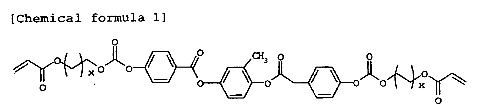
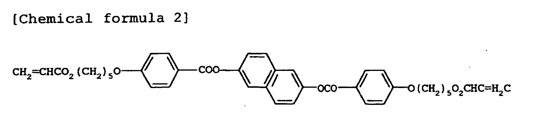




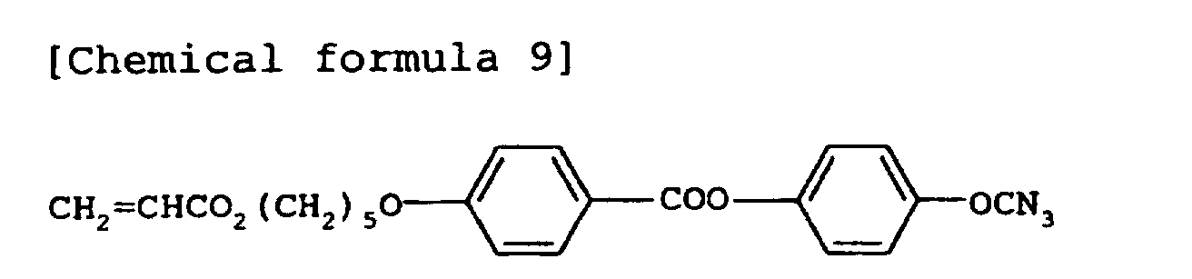
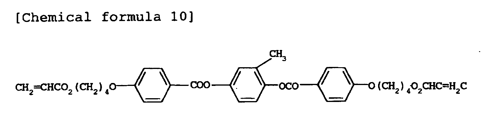

In addition, polymerizable liquid crystal oligomers
or polymers can also be used in this invention. Any one of
known polymerizable liquid crystal oligomers or polymers
may suitably be selected and used.
Furthermore, photopolymerization initiators may be
used as required in this invention. Photopolymerization
initiator may not always be necessary as with the case with,
for example, polymerization of polymerizable liquid crystal
material by irradiation of electron beams, but it is
normally used for the promotion of polymerization in the
commonly used method of curing by irradiation of, e.g.,
ultraviolet rays.
Also, a sensitizing agent may be added in addition to
the photopolymerization initiator, in an amount that does
not inhibit achievement of the object of the invention.
Photopolymerization initiator is generally added in a
range of 0.01 to 20 % by weight; preferably, it is added in
a range of 0.1 to 10 % by weight, and more preferably 0.5
to 5 % by weight, to the polymerizable liquid crystal
material of the invention.
On the other hand, non-polymerizable liquid crystal
materials can also be used in this invention, as noted
above. Any such liquid crystal material can be used as
long as it satisfies the requirement that the orientation
of liquid crystal does not change during the use or storage
thereof as a phase difference layer laminated body as
described above; generally, however, polymer material is
preferable in terms of the temperatures at which the
polymer material transforms into a liquid phase or a liquid
crystal phase. Any commonly used liquid crystal material
that can form a nematic phase in a liquid crystal phase can
be used, including both main-chain and side-chain liquid
crystal polymers.
More specifically, typical examples of main-chain
liquid crystal polymers are polymers such as polyesters,
polyamides, polycarbonates, and polyesterimides.
Further, examples of side-chain liquid crystal
polymers are those that have a backbone structure such as
polyacrylate, polymethacrylate, polysiloxane, and
polymalonate and a low molecular weight liquid crystal
compound (mesogen group) comprising a para-substituted
cyclic compound or the like as a side chain, with or
without a spacer comprising conjugated atoms.
In this invention, the above-mentioned material must
be formed into a phase difference layer having refractive
index anisotropy. Refractive index anisotropy differs
depending on the liquid crystal material being used and the
orientability of the base material surface, but the
following can generally be said: The difference Δn,
expressed as Δn = |nx-ny|, between the indexes of refraction
nx and ny in an X axis and Y axis on a plane parallel to
the orientation of the polymer, the X-axis being orthogonal
and Y-axis being parallel to the orientation direction,
should preferably be 0.05 or more, or more preferably 0.1
or more. A phase difference layer having less refractive
index anisotropy than that may present a problem in regard
to thickness or the like in actual applications.
In this invention, the phase difference layer formed
of the above-mentioned liquid crystal material may have a
certain pattern.
A phase difference layer laminated body having a
patterned phase difference layer is preferably used in, for
example, a three-dimensional liquid crystal display device
or the like, wherein unit cells are divided into groups for
left and right eyes, which are given different degrees of
polarization, thereby creating a three-dimensional image.
Such a patterned phase difference layer laminated body was
conventionally made by manual cutting and bonding of phase
difference layer films comprising common stretched films.
Such technique was problematic in terms of cost and had
limitations on the formation of highly precise patterns.
The present invention overcomes this problem and
provides a phase difference layer laminated body in which a
phase difference layer is formed on the base material in a
highly precise pattern.
In this invention, the pattern formation method
differs depending on the type of liquid crystal material.
That is, the pattern formation method for a polymerizable
liquid crystal material is different from that for a normal
liquid crystal material.
The pattern formation method will be described later
in more detail under the section "manufacturing method of a
phase difference layer laminated body;" in short, in the
case of the polymerizable liquid crystal material, the
irradiation of activating radiation beam for the fixing of
the orientation of liquid crystal material is made in a
certain pattern, and after the polymerization, uncured
portions of liquid crystal material are removed by a
solvent; patterning of the phase difference layer is thus
readily achieved.
In this invention, amongst the polymerizable liquid
crystal materials mentioned above, a polymerizable liquid
crystal monomer is preferably used because of the ease of
the patterning. With a polymerizable liquid crystal
monomer, development is easy, the pattern is more clear-cut,
and formation of more precise pattern is possible.
On the other hand, a photolithography technique using
a photoresist, or a method of applying a normal liquid
crystal material in a certain pattern by a nozzle discharge
or printing technique may be adopted for the pattern
formation method in the case of using a non-polymerizable
polymer liquid crystal material.
In the case of forming the phase difference layer
laminated body in a pattern, the pattern may be any pattern,
for example, striped or zigzagged.
The phase difference layer laminated body of the
invention is comprised of a base material 1 having
orientability, on which is formed the above-described phase
difference layer 2, as shown in Fig. 1.
For the base material having orientability, there are
two cases: One is that the base material 1 itself has
orientability, as shown in Fig. 1, and the other is that an
oriented film 4 is formed on a transparent substrate 3 as
shown in Fig. 2 so that they together function as a base
material 1 having orientability. The followings are
descriptions of these cases as the first and second
embodiments.
In this embodiment, the base material itself has
orientability; specifically, the base material is a
stretched film. With a stretched film, the liquid crystal
material can be oriented along a stretched direction of the
film. Therefore, the processing of the base material is
accomplished simply by preparation of a stretched film,
which is a merit that the processing step is made very
simple. For the stretched film, any commercially available
stretched film can be used, or a stretched film can be made,
according to needs, of various materials.
More specifically, examples of the film include films
made of thermoplastic polymers, such as polycarbonate
polymers, polyester polymers such as polyarylate or
polyethylene terephthalate, polyimide polymers, polysulfone
polymers, polyethersulfon polymers, polystyrene polymers,
polyolefin polymers such as polyethylene or polypropylene,
polyvinyl alcohol polymers, cellulose acetate polymers,
polyvinyl chloride polymers, and polymethylmethacrylate
polymers, and films made of liquid crystal polymers.
In this invention, particularly, polyethylene
terephthalate (PET) film is preferably used, because it has
a wide range of stretch ratio and is readily available.
The stretch ratio of the stretched film used in this
invention is not limited to a particular value, as long as
the film exhibits orientability. Thus, even a biaxially
stretched film can be used, if the stretch ratio differs
between the two axes.
The stretch ratio differs largely depending on the
material used, and there are no particular limits to the
stretch ratio. Generally, materials having a 150 to 300%
stretch ratio can be used; a preferable range is 200 to
250%.
In the second embodiment, the base material having
the above orientability comprises a transparent substrate
and an oriented film formed thereon.
With this embodiment, there is a merit that selection
of the orientated film enables selection of orientation in
a relatively wider range of directions. Selecting the type
of liquid applied on the transparent substrate for forming
the oriented film allows orientation in various directions
and enables even more effective orientation.
An oriented film commonly used for a liquid crystal
display device or the like can favorably be used for the
oriented film of this embodiment; generally, an oriented
film of polyimide that has undergone rubbing treatment is
favorably used.
For the transparent substrate used in this embodiment,
any transparent material can be used, e.g., a transparent
and rigid material having no flexibility such as silica
glass, Pyrex (registered trademark) glass, and synthetic
silica glass, or a transparent and flexible material such
as a transparent resin film, and optical resin sheet or the
like.
In this embodiment, the above oriented film may have
a certain pattern on the surface thereof. That is, the
oriented film may have a pattern with different directions
of orientation, including portions oriented in, at least
two, different directions.
Fig. 4 is a model view showing an oriented film 4
formed with a pattern of different directions of
orientation. Arrows 5 in the drawing indicate the
directions of orientation. Fig. 4 shows one example in
which the oriented film has a checked pattern, but various
other patterns e.g., a striped pattern and the like, may be
employed in accordance with the purposes of use in this
invention.
By thus forming a pattern on the oriented film
surface with different directions of orientation, the phase
difference layer comprising a liquid crystal material
having refractive index anisotropy provided thereon can
have a pattern of refractive index anisotropy conforming to
the pattern on the oriented film surface. As a result, a
phase difference layer laminated body having portions with
different phase differences in a certain pattern can be
obtained, which can be used in various applications.
Patterning on the oriented film surface may be
achieved by a rubbing technique using a mask, or in the
case of using a film oriented with the irradiation of light
beams, by a mask exposure technique or the like.
In addition, the phase difference layer laminated
body of the invention can be formed with other functional
layers such as a protective layer or the like in accordance
with the purposes for which the optical element is to be
used.
If the phase difference layer laminated body of the
invention is used as a λ/4 phase difference layer, it can
be used as a circular polarization plate by bonding a
polarization plate thereto with an adhesive layer
interposed therebetween.
In this invention, also, as shown in Fig. 6 and Fig.
7, two or more phase difference layers can be laminated.
In this case, preferably, the second phase difference layer
is formed after the formation of an oriented film and
rubbing treatment thereof on the first phase difference
layer. The oriented film may be a photo-oriented film
instead.
Fig. 6 shows an example in which a λ/2 phase
difference layer 13 is formed on a glass substrate 11 with
an oriented film 12 interposed therebetween, and a λ/4
phase difference layer 14 is further formed thereon with
another oriented film 12 interposed therebetween. On the
other hand, Fig. 7 shows an example in which a λ/4 phase
difference layer 14 is formed on a glass substrate 11 with
an oriented film interposed therebetween, and a λ/2 phase
difference layer 13 is further formed thereon with another
oriented film 12 interposed therebetween.
By projecting a linearly polarized beam to this phase
difference layer laminated body from the side of the λ/2
phase difference layer 13 or a circularly polarized beam
from the side of the λ/4 phase difference layer 14, the
phase difference layer laminated body can function as a
broadband phase difference plate shown, for example, in
Japanese Patent Laid-Open Publication No. Hei 10-68816.
Furthermore, by attaching a polarization plate on the
opposite surface of the glass substrate 11 with an adhesive
layer 15 interposed therebetween as shown in Fig. 6, it can
function as a broadband circular polarization plate, with a
non-polarized beam incident from the side of the
polarization plate.
Note that, since the fast axes of the λ/2 phase
difference layer 13 and λ/4 phase difference layer 14 need
to be crossed approximately at 60° (60 ± 10°), the two
oriented films should be inclined to each other
approximately at 60° (60 ± 10°). This can be achieved by,
for example, changing the direction of rubbing, or the like.
A method for manufacturing phase difference layer
laminated body according to the invention is characterized
by having:
According to the method for manufacturing a phase
difference layer laminated body of the invention, the
orientation direction can be determined relatively freely
in the orientation processing step, thus offering an
advantage that phase difference layers of various different
directions of fast axis (or slow axis) can be formed.
Fig. 5 shows one example of the method for
manufacturing phase difference layers according to the
invention. In this example, a base material 1 is first
prepared, which includes a transparent substrate 3 on which
is formed an oriented film 4, as shown in Fig. 5(a) (base
material preparation step). Next, a refractive index
anisotropic material layer 6 comprising a polymerizable
liquid crystal material is formed on this base material 1
(application step). This is then let stand under a preset
temperature for orienting the polymerizable liquid crystal
material along the direction of orientation of the oriented
film (orientation processing step). Next, with a photo
mask 7 set thereon, an activating radiation beam 8 such as
ultraviolet light or the like is irradiated, so that
energy-radiated portions of the polymerizable liquid
crystal material are cured in a certain pattern (as shown
in Fig. 5(c), orientation fixing step), and lastly, it is
developed using a solvent for forming the phase difference
layer 2 in the certain pattern; a phase difference layer
laminated body having a phase difference layer 2 in a
pattern on a base material 1 is thus obtained.
The following is a more detailed description of each
step of the manufacturing method of the phase difference
layer laminated body according to the invention.
The first step of the phase difference layer
laminated body manufacturing method of the invention is the
base material preparation step of preparing a base material.
In this invention, different types of base materials
are used depending on the orienting method in the
orientation processing step to be described later. That is,
if the refractive index anisotropic material having an
ability of providing refractive index anisotropy is a
liquid crystal material and if the orienting method in the
orientation processing step uses a base material having
orientability, then it is necessary to prepare a base
material having orientability. On the other hand, if
another method is to be used for the orientation, then the
base material need not have orientability.
Base materials having orientability will not be
described here since they have already been described under
the section "2. Base material having orientability" in "A.
Phase difference layer laminated body" in the foregoing.
On the other hand, substrates in the case where no
such orientability is required may suitably be selected in
accordance with the purposes of use; since transparency is
usually a requirement, a transparent and rigid material
having no flexibility such as silica glass, Pyrex
(registered trademark) glass, and synthetic silica glass,
or a transparent and flexible material such as a
transparent resin film, and optical resin sheet, or the
like may be used, for example.
The next step is the application step of applying a
refractive index anisotropic material having an ability of
providing refractive index anisotropy on the base material.
The first example of the refractive index anisotropic
material having an ability of providing refractive index
anisotropy on the base material used in this invention is a
liquid crystal material. The liquid crystal material is
not described here since it has already been described
under the section "1. Phase difference layer" in "A. Phase
difference layer laminated body" in the foregoing.
For forming a refractive index anisotropic material
layer using a polymerizable liquid crystal material, it is
necessary to achieve polymerization using an activating
radiation beam in the orientation fixing step to be
described later. Depending on the type of the activating
radiation beam, a photopolymerization initiator may be used
as required, for instance in the case of UV curing.
Specific examples of such a photopolymerization initiator
are Irg 369, Irg 907, Irg 184 (trade name) and the like,
manufactured by Ciba Specialty Chemicals Corp.
Refractive index anisotropic materials other than
liquid crystal materials include materials that form layers
and exhibit refractive index anisotropy when the molecules
are more or less oriented in certain directions. Any
materials that can usually be made to function as a phase
difference layer by stretching may be used: Such materials
include thermoplastic polymers such as polycarbonate
polymers, polyester polymers such as polyarylate or
polyethylene terephthalate, polyimide polymers, polysulfone
polymers, polyethersulfon polymers, polystyrene polymers,
polyolefin polymers such as polyethylene or polypropylene,
polyvinyl alcohol polymers, cellulose acetate polymers,
polyvinyl chloride polymers, and polymethylmethacrylate
polymers.
In this invention, particularly, a refractive index
anisotropic material that has relatively high polarity is
preferable so that it can be oriented by applying a high
electric or magnetic field in the orientation processing
step to be described later for performing orientation
processing. A specific example is a side-chain modified
phonoxy resin into which 4-nitrophenyl carbamate is
introduced.
In the application step, for example, the above
material is dissolved in a solvent or the like to form an
application liquid, which is applied using various
application methods such as spin coating, casting, dipping,
bar coating, blade coating, roll coating, spray coating,
and the like.
In the case of the application using a solvent, a
drying step is necessary after the application for removing
the solvent.
On the other hand, a refractive index anisotropic
material that melts and liquefies at a temperature at which
the material itself does not decompose or inflict damage on
the base material, can be applied in a heated state without
solvent. Same application methods as listed above can be
used in this case, too.
In this invention, the more preferable method for the
ease of handling is the method of dissolving the above-mentioned
material in a solvent and applying the same.
Because a polymerizable liquid crystal material is
favorably used in this invention as noted above, it is
particularly preferable to use a solution of this material
as the application liquid.
Any solvents in which the above polymerizable liquid
crystal material or the like can be dissolved, and which do
not inhibit the orientability of the base material, may be
used for this purpose.
Specific examples of solvents include hydrocarbons
such as benzene, toluene, xylene, n-butylbenzene,
diethylbenzene, and tetralin, ethers such as metoxybenzene,
1,2-dimetoxybenzene, and diethylene glycol dimethylether,
ketones such as acetone, methylethylketone,
methylisobutylketone, cyclohexanone, and 2,4-pentanedion,
esters such as ethyl acetate, ethylene glycol monomethyl
ether acetate, propylene glycol monomethyl ether acetate,
propylene glycol monoethyl ether acetate, and γ-butyrolactone,
amide solvents such as 2-pyrrolidone, N-methyl-2-pyrrolidone,
dimethyl formamide, and
dimethylacetamide, halogenated solvents such as chloroform,
dichloromethane, carbon tetrachloride, dichloroethane,
tetrachloroethane, trichloroethylene, tetrachloroethylene,
chlorobenzene, and ortho-dichlorobenzene, alcohols such as
t-butylalcohol, diacetone alcohol, glycerin, monoacetin,
ethylene glycol, triethylene glycol, hexylene glycol,
ethylene glycol monomethyl ether, ethyl cellosolve, and
butyl cellosolve the like, phenols such as phenol, and
para-chlorophenol; these can be used either alone or in
combination.
The solubility of the polymerizable liquid crystal
material or the like may not be sufficient, or the above
substrate having orientability may be corroded with the use
of a single type of solvent. Such troubles can be avoided
by using a mixture of two or more types of solvents. Among
the above-listed solvents, hydrocarbon solvents and glycol
mono ether acetate solvents are favorably used alone, while
ethers and ketones are favorably used in mixture with
glycols. There is no generic rule regarding the
concentration of the solution because it should be
determined depending on the solubility of liquid crystal
compositions and the film thickness of phase difference
layers to be fabricated; it is, however, usually within a
range of 1 to 60 % by weight, and more preferably 3 to 40 %
by weight.
In this invention, there may be cases where the phase
difference layer should preferably be formed in a certain
pattern on the substrate as described above. In such a
case, a nozzle discharge technique such as an inkjet method
or the like, or a printing technique such as photogravure
or the like may be employed in this application step for
patterned application. In the case where a highly precise
pattern is needed, the base material may undergo a
preparatory step of forming a pattern consisting of
hydrophilic regions and water-repellent regions for giving
wettability, the patterned application being made to the
hydrophilic regions.
The next step, in this invention, is the orientation
processing step of performing orientation processing to the
refractive index anisotropic material layer applied on the
base material. The orientation processing step according
to the invention includes two methods: One method uses a
base material having orientability, the other achieves
orientation by applying force to molecules of the
refractive index anisotropic material. Each method is
respectively described below.
This method using a base material having
orientability can be employed in the orientation processing
step of the invention when the above-described liquid
crystal material is used for the refractive index
anisotropic material.
In the case of using a base material having
orientability, the refractive index anisotropic material,
or the liquid crystal material in this case, formed on the
base material having orientability is heated to a
temperature at which it can form a liquid crystal phase,
the temperature being maintained the same until the liquid
crystal material is oriented along directions defined by
the base material.
The temperature and duration of time for which it is
maintained depend largely on the liquid crystal material
used and the orientability of the base material; they
should suitably be set in accordance with the types of the
liquid crystal material and base material having
orientability.
Incidentally, a base material comprising a
transparent substrate and an oriented film formed thereof
to have orientability can be used with favorable results
because of a wider range of selection of orientation
direction or the direction of fast axis (or slow axis) of
phase difference layer, and because the use of the oriented
film makes possible to give a pattern to the orientation
directions, as has been described under the section "2.
Base material having orientability" in "A. Phase difference
layer laminated body" in the foregoing.
In this invention, apart from the method using a base
material having orientability, the refractive index
anisotropic material having an ability of providing
refractive index anisotropy can be oriented by a method of
applying force to molecules.
In this orienting method of applying force to
molecules, after heating the refractive index anisotropic
material formed on the base material in the above
application step to a temperature at least exceeding a
temperature Tg at which molecules are movable inside the
layer, force is applied to the molecules to orient them in
certain directions.
Examples of such a force applying method include a
method of applying a powerful electrostatic field, and a
method of applying a powerful magnetic field, and the like.
While the above method using a base material having
orientability can use only a liquid crystal material as the
refractive index anisotropic material, this method can
employ, not only liquid crystal materials, but also any
material that has an ability of providing refractive index
anisotropy.
If an electrostatic field is to be used, for example,
for applying a force to the molecules, a refractive index
anisotropic material having a molecular structure that can
receive a force induced by an electrostatic field may be
used; specifically, a material having polarity may be used.
Similarly, if a magnetic field is to be used, a refractive
index anisotropic material having a molecular structure
that can receive a force induced by a magnetic field may be
used; in this case also, a material having polarity may be
used. The material, in this case, should have refractive
index anisotropy as well as polarity, but it should not be
limited to a polymer material; for example, a polymerizable
monomer or oligomer may also be used. Any material can be
used as long as it exhibits refractive index anisotropy by
polymerization by, e.g., irradiation of an activating
radiation beam in a state where the molecules are oriented
by an electric or magnetic field.
According to this method, the orientation direction,
i.e., the direction of fast axis (or slow axis) of phase
difference layer, can readily be changed, e.g., by control
of the position of an electromagnetic or magnetic field.
Orientation is therefore possible in any direction, whereby
the resultant phase difference layer laminated body has a
merit that it can be used in a very wide range of
applications.
In this invention, an orientation fixing step is
carried out for fixing the given orientation of the
refractive index anisotropic material layer that has
undergone the above orientation processing.
This orientation fixing step may be performed along
with the orientation processing step, or after the
orientation processing step has been completed. If, for
example, the above orientation processing step employs a
method using an electrostatic field, then the orientation
fixing step, in which temperature is lowered in this case,
may be performed while applying the electrostatic field.
In this invention, the orientation fixing step is
carried out in different manners depending on the
refractive index anisotropic material being used.
Specifically, there are two cases; one is that the
refractive index anisotropic material is a polymerizable
material, and the other is that it is a non-polymerizable
polymer material. Both cases, wherein the refractive index
anisotropic material is a polymerizable material, and a
non-polymerizable polymer material, are separately
described below.
In this invention, for the refractive index
anisotropic material, polymerizable liquid crystal
materials such as polymerizable monomers, polymerizable
oligomers, and polymerizable liquid crystal polymers are
preferably used as noted above.
In the orientation fixing step in which such a
polymerizable liquid crystal material is used, an
activating radiation beam, which promotes polymerization,
is irradiated to the refractive index anisotropic material
layer comprising the polymerizable liquid crystal material
formed on the base material having orientability.
"Activating radiation beam" mentioned in this
invention means radiation rays that are capable of inducing
polymerization in a polymerizable material, which may
contain, if required, a polymerization initiator.
In this invention, a preferable method is that UV ray
is used as the activating radiation beam for a
polymerizable liquid crystal material, which contains a
polymerization initiator that generates radicals for
inducing radical polymerization upon irradiation of the UV
rays. This is because the method using UV ray as the
activating radiation beam is a well-established technique
including the polymerization initiator used therewith, and
can readily be applied to this invention.
This orientation fixing step with irradiation of an
activating radiation beam may be performed at the same
processing temperature as that in the above orientation
processing step, i.e., the temperature at which the
polymerizable liquid crystal material transforms into a
liquid crystal phase, or lower than that. A temperature
drop after the polymerizable liquid crystal material has
transformed into a liquid crystal phase does not cause a
disorder in the orientation.
Other polymerizable materials that have no liquid
crystal properties may also be used for the polymerizable
material as noted above; the orientation fixing step can be
performed similarly in this case, too.
The refractive index anisotropic material having an
ability of providing refractive index anisotropy can be a
non-polymerizable polymer material when, for example, it is
a liquid crystal material other than the above-mentioned
polymerizable liquid crystal materials, i.e., one of
commonly known non-polymerizable liquid crystal polymers.
The orientation fixing step in the case of using such
a liquid crystal polymer is a step of lowering the
temperature at which the polymer transforms into a liquid
crystal phase to the temperature at which the polymer
transforms into a solid phase. In the above orientation
processing step, by the orientation processing, the liquid
crystal polymer has transformed into a liquid crystal phase
having a nematic structure along the orientation defined by
the base material having orientability. In this state, by
setting the temperature at which liquid crystal transforms
to a glass state, the polymer can be made into a phase
difference layer having, as a whole, refractive index
anisotropy.
On the other hand, if the above orientation
processing step employs an orienting method with
application of force to molecules, fixing of the
orientation of molecules can similarly be achieved by
lowering the temperature in the oriented state. Thereby, a
phase difference layer having, as a whole, refractive index
anisotropy can be obtained. The temperature, in this case,
should preferably be lowered to a level lower than the
glass transition temperature Tg.
In this invention, depending on the purposes of use,
the phase difference layer formed on the base material may
be required to have a certain pattern, as mentioned above.
Patterning may be achieved in the above application step as
described above, but in terms of pattern precision, it is
preferable to perform the patterning in this orientation
fixing step. That is, in the case of using the above-mentioned
polymerizable material, patterning of the phase
difference layer can readily be achieved by irradiation of
the activating radiation beam in a pattern for forming
polymerized portions in a pattern, followed by a
development step using a solvent or the like.
Examples of solvents that can be used for the
development include acetone, 3-methoxybutyl acetate,
diglyme, cyclohexanone, tetrahydrofuran, toluene, methylene
chloride, and methyl ethyl ketone or the like.
A favorable method of irradiating the material with
the activating radiation beam in a pattern is a method
using a photo mask as shown in Fig. 5, but it is not
limited to this; a laser beam, for example, may be used as
the activating radiation beam, the irradiation being
performed as if to draw a line.
In this invention, if the development is performed
using the solvent or the like thereafter, then it is
preferable that the cured portions of the polymerizable
liquid crystal material have cured to a degree of 85% by
the above activating radiation beam. Thereby,
deterioration of optical characteristics of the cured
portions or swelling thereof during the development
thereafter using a solvent are effectively prevented.
In the case of using a non-polymerizable material, on
the other hand, patterning may be achieved by a
photolithography technique using a photoresist.
By the above orientation fixing step, a phase
difference layer laminated body having a phase difference
layer on the base material is obtained: In this invention,
further, other functional layers such as a protective layer
may be added according to needs.
Also, if the phase difference layer laminated body of
the invention is a λ/4 phase difference layer, a further
step may be included for bonding a polarization plate with
an adhesive layer thereto. Thereby, circular polarization
plates can be fabricated.
Furthermore, since the phase difference layer
laminated body may have two or more laminated phase
difference layers as shown in Fig. 6 and Fig. 7, the above
application step, orientation processing step, and
orientation fixing step may be repeated twice or more. If
the orientation processing is achieved by the use of an
oriented film as with the examples shown in Fig. 6 and Fig.
7, it is preferable to perform an oriented film formation
step after the orientation fixing step.
The liquid crystal display device of the invention is
characterized by the use of a phase difference layer
laminated body described in the section "A. Phase
difference layer laminated body" above, and particularly, a
preferable embodiment is a liquid crystal display device
using a phase difference layer laminated body having the
phase difference layer formed in a pattern on the base
material.
As described above, the phase difference layer
laminated body using a polymerizable liquid crystal
material, particularly a polymerizable liquid crystal
monomer, can readily be formed with a phase difference
layer formed on the base material in a highly precise
pattern, by patterned irradiation of an activating
radiation beam using, e.g., a photo mask, in the
orientation fixing step; a liquid crystal display device in
which is incorporated such a phase difference layer
laminated body having a phase difference layer in a highly
precise pattern will have an unrivaled high quality.
One example of a liquid crystal display device is a
three-dimensional liquid crystal display device shown, for
example, in Japanese Patent Laid-Open Publication No. Hei
9-304740; the phase difference layer laminated body having
a patterned phase difference layer on a base material may
be used for the phase difference plates of this device that
cover the entire liquid crystal display panel in a striped
manner.
Another example is a projection type display device
shown, for example, in Japanese Patent Laid-Open
Publication No. Hei 8-234205; the phase difference layer
laminated body having a patterned phase difference layer on
a base material may be used for the λ/2 phase difference
plates formed in a pattern in this projection type display
device.
Yet another preferred embodiment is a liquid crystal
display device 50 shown in Fig. 8 to Fig. 10, including the
following: A liquid crystal display element 56 including a
liquid crystal layer 52 and a plurality of unit cells 54
that constitute a multiplicity of pixels, liquid crystal
molecules on the surface of the liquid crystal layer 52
being oriented with a plurality of different directors in
directions indicated by arrows in Fig. 10 in each of the
unit cells 54; and phase difference layers (phase
difference optical elements) 60 arranged on both sides in
the thickness direction of the liquid crystal display
element 56, the phase difference layers divided into a
plurality of (four in this embodiment) oriented
compensation regions 58A, 58B, 58C, 58D in accordance with
the directions of the liquid crystal directors in each unit
cell 54, the liquid crystal substance being oriented and
fixed in each of the oriented compensation regions 58A, 58B,
58C, 58D.
The liquid crystal display element 56 is an MVA type;
it has the liquid crystal layer 52 sealed between a pair of
oriented films 62, 63, as shown in Fig. 9. Reference
numerals 66, 68, and 70 denote transparent electrodes,
transparent base material, and polarization plates,
respectively.
Further, as shown in Fig. 10, the liquid crystal
molecules on the surface of the liquid crystal layer 52 are
oriented with the directors in symmetric directions
relative to the center of each unit cell 54. Specifically,
one of the oriented films 62 is formed with a semi-spherical
rib 62A protruded at the center of each cell 54,
as shown in Fig. 9, and the liquid crystal molecules on the
surface of the liquid crystal layer 52 are oriented at
angles radiating from the rib 62A.
Each unit cell 54 has four oriented compensation
regions 58A, 58B, 58C, 58D that are defined by dividing the
unit cell 54 into a plurality of (four in this embodiment)
sections with an equal angular spacing around the center,
and the liquid crystal substance divided into these
oriented compensation regions 58A, 58B, 58C, 58D is
oriented and fixed.
By thus orienting the molecules in the phase
difference layer 60 for each of the oriented compensation
regions 58A, 58B, 58C, 58D in accordance with the
directions of the liquid crystal directors of the liquid
crystal layer 52, optical compensation is made possible in
more precise and various ways than conventionally practiced,
whereby the problem of visual dependency is much improved
and high-quality image display is realized.
Divisional orientation and fixation of the liquid
crystal substance to form the oriented compensation regions
may be achieved either by coating a liquid crystal
substance having nematic properties on the substrate and
orienting it in a certain direction using an electrostatic
or magnetic field, followed by a fixing step of irradiating
UV rays or the like using a photo mask, these steps being
repeated for each of the oriented compensation regions; or,
by coating the liquid crystal substance on an oriented film
that has been processed to have different orientation
directions for each of the oriented compensation regions by
a mask rubbing technique, followed by fixing of the liquid
crystal in the oriented state.
In this embodiment, the liquid crystal molecules on
the surface of the liquid crystal layer 52 are oriented
with the directors in symmetric directions relative to the
center of each unit cell 54, but one alternative is to
divide each unit cell 54 of the liquid crystal display
element 56 into a plurality of (four in this embodiment)
oriented display regions 72A, 72B, 72C, 72D, the liquid
crystal molecules on the surface of the liquid crystal
layer 52 being oriented in respective directions of the
oriented display regions 72A, 72B, 72C, 72D, and to form
the oriented compensation regions 58A, 58B, 58C, 58D
correspondingly to the oriented display regions 72A, 72B,
72C, 72D.
Orientation processing of the oriented film 59 to
form the oriented display regions 72A, 72B, 72C, 72D with
different orientation directions may be achieved by the use
of a square pyramid rib, or by a known photo-oriented film
method or the like.
By thus orienting the molecules in the phase
difference layer for each of the oriented compensation
regions in accordance with the orientation of liquid
crystal molecules of each of the oriented display regions,
even more precise optical compensation can be realized.
In the above embodiment, each unit cell 54 of the
liquid crystal display element 56 is divided into four
oriented display regions, but the invention is not limited
to this; for example, a triangular prism or pyramid rib may
be formed on the oriented film to divide each unit cell of
the liquid crystal display element into two or three
oriented display regions, or, a polygonal pyramid rib of
more than five base sides may be formed on the oriented
film to divide each unit cell of the liquid crystal display
element into five or more oriented display regions. It
goes without saying that the effect of improving display
quality is also obtained in these cases.
Incidentally, the semi-spherical rib 62A mentioned
above divides each unit cell of the liquid crystal display
element into an infinite number, as it were, of oriented
display regions.
Similarly, each unit cell of the phase difference
layer may be divided into two or three oriented display
regions, or it may be divided into five or more oriented
display regions.
In the above embodiment, the phase difference layer
60 has four oriented compensation regions 72A, 72B, 72C,
72D corresponding to the four oriented display regions 58A,
58B, 58C, 58D of the unit cell 60 of the liquid crystal
display element 54, but the invention is not limited to
this; a plurality of oriented compensation regions of
optical compensation elements may be provided relative to
one oriented display region in the unit cell. Thereby,
even more precise and variant optical compensation can be
realized.
Also, although the phase difference layers 56 are
arranged on both sides in the thickness direction of the
liquid crystal display element 54 in the above embodiment,
the invention is not limited to this; the phase difference
layer may be arranged only on one side in the thickness
direction of the liquid crystal display element, depending
on the manner in which optical compensation is carried out.
Also, although the liquid crystal display element 56
is an MVA type in the above embodiment, the invention is
not limited to this; the invention can obviously be applied
to other types of liquid crystal display elements including
other VA types such as a PVA type, and TN type, STN type,
IPS type, OCB type, and ECB type or the like.
Furthermore, the invention should not be limited to
the above-described embodiments, which were given only by
way of example; the technical scope of the invention
includes any other constructions substantially identical to
and having similar effects as those of the technical ideas
defined by the claim of the invention.
For example, while the material used for the phase
difference layer has been described as a liquid crystal
material that can form a nematic phase under the section "A.
Phase difference layer laminated body" above, any liquid
crystal material that does not form a cholesteric phase can
be used without any problems in this invention; thus a
liquid crystal material that forms a smectic phase should
also be included in the definition of liquid crystal in
this invention.
An example will be described below for further
explanation of the invention.
A solution of polymerizable liquid crystal monomer in
toluene was prepared, the monomer having a mesogen in the
center, polymerizable acrylate at either end, and a spacer
linking therebetween, and having a liquid crystal-isotropic
transition temperature (temperature at which liquid crystal
transforms into an isotropic phase) of 100°C. Note that, a
photopolymerization initiator (Irg 184: Ciba Specialty
Chemicals Corp.) was added to the above solution in toluene
in an amount of 5% by weight relative to the monomer
molecules.
Meanwhile, polyimide was applied on a glass substrate
to form a coat, which then underwent rubbing treatment in
certain directions, to form an oriented film.
This glass substrate with the oriented film was then
set in a spin coater, and the above solution in toluene was
applied onto the oriented film to a thickness of about 5µm
by spin coating.
Next, the substrate was heated at 80°C for one minute
to vaporize toluene in the solution, after which it was
confirmed that the liquid crystal film (uncured liquid
crystal film) formed on the oriented film was in a nematic
phase.
UV rays were then irradiated at 100mJ/cm2 to the
uncured nematic liquid crystal film by a UV irradiation
apparatus, with the use of a photo mask having openings in
a certain pattern. The UV irradiation intensity was set so
that UV-irradiated portions of the nematic liquid crystal
film would polymerize (cure) to a degree of 90% or more.
Thereafter, the glass substrate with the oriented
film formed with the nematic liquid crystal film was
immersed in acetone with rocking motion applied thereto for
one minute so as to remove uncured portions of the nematic
liquid crystal film.
Finally, the above glass substrate was taken out from
acetone and dried; a phase difference layer laminated body
having a phase difference layer with a desired pattern was
thus fabricated, the nematic liquid crystal film being
formed in UV-irradiated portions, while the oriented film
being exposed in other portions.
Incidentally, the nematic liquid crystal film formed
in this example had a substantially uniform film thickness
of 1.5 µm, and the pattern was formed with a very high
degree of precision.
According to the present invention, a liquid crystal
material that can form a nematic phase is used for forming
a phase difference layer in a pattern, and orientation
directions are readily determined by selecting the type of
liquid crystal materials and base materials having
orientability; thus the invention provides a phase
difference layer laminated body that can be applied to
various optical elements.
Claims (38)
- A phase difference layer laminated body characterized by having a base material having orientability, and a phase difference layer made of a liquid crystal material that can form a nematic phase and formed in a pattern on said base material such as to have refractive index anisotropy.
- The phase difference layer laminated body according to claim 1, wherein
said liquid crystal material that can form a nematic phase is obtained by polymerization of at least one of a polymerizable liquid crystal monomer, a polymerizable liquid crystal oligomer, and a polymerizable liquid crystal polymer. - The phase difference layer laminated body according to claim 1, wherein
said liquid crystal material that can form a nematic phase is obtained by polymerization of a polymerizable liquid crystal monomer. - The phase difference layer laminated body according to any one of claims 1 to 3, wherein
said base material having orientability is obtained by forming an oriented film on a transparent substrate. - The phase difference layer laminated body according to claim 4, wherein
said oriented film is formed in a pattern with portions that are oriented in at least two different directions, and wherein said liquid crystal material on said oriented film has refractive index anisotropy that conforms to the plurality of directions of orientation of said oriented film. - The phase difference layer laminated body according to any one of claims 1 to 3, wherein
said base material having orientability is a stretched film. - A method for manufacturing a phase difference layer laminated body characterized by having:a base material preparation step of preparing a base material;an application step of applying a refractive index anisotropic material having an ability of providing refractive index anisotropy on said base material for forming a refractive index anisotropic material layer;an orientation processing step of performing orientation processing to said refractive index anisotropic material layer;an orientation fixing step of fixing the orientation of said refractive index anisotropic material layer that has undergone the orientation processing in said orientation processing step; anda patterning step of giving a pattern to said refractive index anisotropic material layer.
- The method for manufacturing a phase difference layer laminated body according to claim 7, wherein
said base material is a base material having orientability, said refractive index anisotropic material is a liquid crystal material that can form a nematic phase, and said orientation processing step is a step of maintaining said refractive index anisotropic material layer in a temperature at which said liquid crystal material transforms into a liquid crystal phase. - The method for manufacturing a phase difference layer laminated body according to claim 8, wherein
said liquid crystal material is a material having at least one of a polymerizable liquid crystal monomer, a polymerizable liquid crystal oligomer, and a polymerizable liquid crystal polymer, and wherein said orientation fixing step is a step of irradiating, with an activating radiation beam, said material having at least one of the polymerizable liquid crystal monomer, the polymerizable liquid crystal oligomer, and the polymerizable liquid crystal polymer for polymerization thereof. - The method for manufacturing a phase difference layer laminated body according to claim 8, wherein
said liquid crystal material is a polymerizable liquid crystal monomer. - The method for manufacturing a phase difference layer laminated body according to claim 9 or 10, wherein
said activating radiation beam irradiation step is a step of irradiating the material with the activating radiation beam in a pattern, and wherein the method further comprises a development step of developing unpolymerized portions of the liquid crystal material, after said step of irradiating the material with the activating radiation beam in the pattern. - The method for manufacturing a phase difference layer laminated body according to any one of claims 8 to 10, wherein
said base material having orientability is obtained by forming an oriented film on a transparent substrate. - The method for manufacturing a phase difference layer laminated body according to claim 11, wherein
said base material having orientability is obtained by forming an oriented film on a transparent substrate. - The method for manufacturing a phase difference layer laminated body according to claim 12, wherein
said oriented film is formed in a pattern with portions that are oriented in at least two different directions, and wherein said liquid crystal material on said oriented film has refractive index anisotropy that conforms to the plurality of directions of orientation of said oriented film. - The method for manufacturing a phase difference layer laminated body according to claim 13, wherein
said oriented film is formed in a pattern with portions that are oriented in at least two different directions, and wherein said liquid crystal material on said oriented film has refractive index anisotropy that conforms to the plurality of directions of orientation of said oriented film. - The method for manufacturing a phase difference layer laminated body according to any one of claims 8 to 10, wherein
said base material having orientability is a stretched film. - The method for manufacturing a phase difference layer laminated body according to claim 11, wherein
said base material having orientability is a stretched film. - A liquid crystal display device characterized by using a phase difference layer laminated body comprising a base material having orientability, and a phase difference layer made of a liquid crystal material that can form a nematic phase and formed in a pattern on said base material such as to have refractive index anisotropy.
- The liquid crystal display device according to claim 18, wherein
the liquid crystal material that can form a nematic phase of said phase difference layer laminated body is obtained by polymerization of at least one of a polymerizable liquid crystal monomer, a polymerizable liquid crystal oligomer, and a polymerizable liquid crystal polymer. - The liquid crystal display device according to claim 18, wherein
the liquid crystal material that can form a nematic phase of said phase difference layer laminated body is obtained by polymerization of a polymerizable liquid crystal monomer. - The liquid crystal display device according to any one of claims 18 to 20, wherein
the base material having orientability of said phase difference layer laminated body is obtained by forming an oriented film on a transparent substrate. - The liquid crystal display device according to claim 21, wherein
the oriented film of said phase difference layer laminated body is formed in a pattern with portions that are oriented in at least two different directions, and wherein said liquid crystal material on said oriented film has refractive index anisotropy that conforms to the plurality of directions of orientation of said oriented film. - The liquid crystal display device according to any one of claims 18 to 20, wherein
the base material having orientability of said phase difference layer laminated body is a stretched film. - A liquid crystal display device comprising:a liquid crystal display element including a liquid crystal layer and comprising a plurality of unit cells that constitute a multiplicity of pixels, liquid crystal molecules on a surface of said liquid crystal layer being orientable in directions of a plurality of different directors in each of said unit cells; anda phase difference optical element arranged at least on one side in a thickness direction of said liquid crystal display element, the phase difference optical element being divided into a plurality of oriented compensation regions in accordance with the directions of the directors for said liquid crystal molecules in said each unit cell, liquid crystal substance being oriented and fixed in each of said oriented compensation regions.
- The liquid crystal display device according to claim 24, wherein
said each unit cell of said liquid crystal display element is divided into a plurality of oriented display regions, the liquid crystal molecules on the surface of said liquid crystal layer being oriented in different directions of directors for each of said oriented display regions, and wherein said oriented compensation regions are formed in said phase difference optical element corresponding to said oriented display regions. - The liquid crystal display device according to claim 25, wherein
a plurality of said oriented compensation region is formed in said phase difference optical element relative to one said oriented display region of said unit cell. - The liquid crystal display device according to claim 25 or 26, wherein
the oriented display regions of said liquid crystal display element are formed in such a manner as to divide said each unit cell into four or more sections with an equal angular spacing around a center of said each unit cell. - The liquid crystal display device according to claim 24, wherein
the liquid crystal molecules on the surface of said liquid crystal layer of said liquid crystal display element are oriented with the directors in symmetric directions relative to respective centers of the unit cells. - The liquid crystal display device according to claim 27, wherein
the oriented compensation regions of said phase difference optical element are formed in such a manner as to divide said each unit cell into four or more sections with an equal angular spacing around respective centers of the unit cells. - The liquid crystal display device according to claim 28, wherein
the oriented compensation regions of said phase difference optical element are formed in such a manner as to divide said each unit cell into four or more sections with an equal angular spacing around a center of said each unit cell. - The liquid crystal display device according to claim 29, wherein
a pair of 180° opposite oriented compensation regions relative to the center of said each unit cell of said phase difference optical element are oriented in the same direction. - The liquid crystal display device according to any one of claims 24 to 26, 28, and 30, wherein
said liquid crystal display element is driven by a method of one of TN type, STN type, VA type, MVA type, PVA type, IPS type, OCB type, and ECB type. - The liquid crystal display device according to any one of claims 24 to 26, 28, and 30, wherein
said phase difference optical element comprises a base material having orientability, and a phase difference layer made of a liquid crystal material that can form a nematic phase and formed in a pattern on said base material such as to have refractive index anisotropy. - The liquid crystal display device according to claim 33, wherein
the liquid crystal material that can form a nematic phase of said phase difference layer laminated body is obtained by polymerization of at least one of a polymerizable liquid crystal monomer, a polymerizable liquid crystal oligomer, and a polymerizable liquid crystal polymer. - The liquid crystal display device according to claim 33, wherein
the liquid crystal material that can form a nematic phase of said phase difference layer laminated body is obtained by polymerization of a polymerizable liquid crystal monomer. - The liquid crystal display device according to claim 33, wherein
the base material having orientability of said phase difference layer laminated body is obtained by forming an oriented film on a transparent substrate. - The liquid crystal display device according to claim 36, wherein
the oriented film of said phase difference layer laminated body is formed in a pattern with portions that are oriented in at least two different directions, and wherein said liquid crystal material on said oriented film has refractive index anisotropy that conforms to the plurality of directions of orientation of said oriented film. - The liquid crystal display device according to claim 33, wherein
the base material having orientability of said phase difference layer laminated body is a stretched film.
Priority Applications (2)
| Application Number | Priority Date | Filing Date | Title |
|---|---|---|---|
| EP10012826A EP2309292A3 (en) | 2001-11-08 | 2002-11-07 | A liquid crystal display device |
| EP08008186A EP1967873A3 (en) | 2001-11-08 | 2002-11-07 | A liquid crystal display device |
Applications Claiming Priority (5)
| Application Number | Priority Date | Filing Date | Title |
|---|---|---|---|
| JP2001343873 | 2001-11-08 | ||
| JP2001343873 | 2001-11-08 | ||
| JP2002259150A JP2003207641A (en) | 2001-11-08 | 2002-09-04 | Retardation layer laminate and method for producing the same |
| JP2002259150 | 2002-09-04 | ||
| PCT/JP2002/011601 WO2003040786A1 (en) | 2001-11-08 | 2002-11-07 | Phase difference layer laminate and method for production thereof |
Related Child Applications (1)
| Application Number | Title | Priority Date | Filing Date |
|---|---|---|---|
| EP08008186A Division EP1967873A3 (en) | 2001-11-08 | 2002-11-07 | A liquid crystal display device |
Publications (2)
| Publication Number | Publication Date |
|---|---|
| EP1452892A1 true EP1452892A1 (en) | 2004-09-01 |
| EP1452892A4 EP1452892A4 (en) | 2007-11-21 |
Family
ID=26624430
Family Applications (3)
| Application Number | Title | Priority Date | Filing Date |
|---|---|---|---|
| EP10012826A Withdrawn EP2309292A3 (en) | 2001-11-08 | 2002-11-07 | A liquid crystal display device |
| EP08008186A Withdrawn EP1967873A3 (en) | 2001-11-08 | 2002-11-07 | A liquid crystal display device |
| EP02780035A Withdrawn EP1452892A4 (en) | 2001-11-08 | 2002-11-07 | Phase difference layer laminate and method for production thereof |
Family Applications Before (2)
| Application Number | Title | Priority Date | Filing Date |
|---|---|---|---|
| EP10012826A Withdrawn EP2309292A3 (en) | 2001-11-08 | 2002-11-07 | A liquid crystal display device |
| EP08008186A Withdrawn EP1967873A3 (en) | 2001-11-08 | 2002-11-07 | A liquid crystal display device |
Country Status (7)
| Country | Link |
|---|---|
| US (3) | US20040189909A1 (en) |
| EP (3) | EP2309292A3 (en) |
| JP (1) | JP2003207641A (en) |
| KR (1) | KR100727199B1 (en) |
| CN (1) | CN1520525A (en) |
| TW (1) | TWI253522B (en) |
| WO (1) | WO2003040786A1 (en) |
Cited By (3)
| Publication number | Priority date | Publication date | Assignee | Title |
|---|---|---|---|---|
| WO2008132206A1 (en) * | 2007-04-30 | 2008-11-06 | Seereal Technologies S.A. | Light modulator for representing complex-valued data |
| US7462381B2 (en) | 2002-04-26 | 2008-12-09 | Nitto Denko Corporation | Method for producing birefringent film |
| US10207474B2 (en) | 2015-01-28 | 2019-02-19 | Zeon Corporation | Multilayer film, optically anisotropic layered body, circularly polarizing plate, organic electroluminescence display device, and manufacturing method |
Families Citing this family (35)
| Publication number | Priority date | Publication date | Assignee | Title |
|---|---|---|---|---|
| JP2003207641A (en) * | 2001-11-08 | 2003-07-25 | Dainippon Printing Co Ltd | Retardation layer laminate and method for producing the same |
| US20110013121A1 (en) | 2001-11-08 | 2011-01-20 | Dai Nippon Printing Co., Ltd. | Phase difference layer laminated body for three dimensional liquid crystal display device and manufacturing method thereof |
| US7324180B2 (en) | 2002-09-06 | 2008-01-29 | Dai Nippon Printing Co., Ltd. | Laminated retardation optical element, process of producing the same, and liquid crystal display |
| JP2005215115A (en) * | 2004-01-28 | 2005-08-11 | Fujitsu Display Technologies Corp | Liquid crystal display |
| JP4580188B2 (en) * | 2004-05-27 | 2010-11-10 | 富士通株式会社 | Liquid crystal display device and manufacturing method thereof |
| KR101066483B1 (en) | 2004-06-30 | 2011-09-22 | 엘지디스플레이 주식회사 | Liquid crystal display and manufacturing method thereof |
| TW200702772A (en) * | 2005-03-03 | 2007-01-16 | Fuji Photo Film Co Ltd | Liquid crystal cell and liquid crystal display apparatus |
| JP4553769B2 (en) * | 2005-03-29 | 2010-09-29 | 大日本印刷株式会社 | Optical element manufacturing method |
| JP2007206218A (en) * | 2006-01-31 | 2007-08-16 | Topcon Corp | Optical element and moisture-proof coating method thereof |
| JP5183165B2 (en) | 2006-11-21 | 2013-04-17 | 富士フイルム株式会社 | Method for producing article having birefringence pattern |
| JP4529984B2 (en) * | 2007-02-26 | 2010-08-25 | エプソンイメージングデバイス株式会社 | Liquid crystal device and electronic device |
| JP5251354B2 (en) * | 2008-08-15 | 2013-07-31 | 凸版印刷株式会社 | Retardation substrate, manufacturing method thereof, and liquid crystal display device |
| KR101528494B1 (en) * | 2008-08-27 | 2015-06-12 | 삼성디스플레이 주식회사 | Array substrate, liquid crystal display panel having the same, and method of manufacturing the liquid crystal display panel |
| EP2163923B1 (en) * | 2008-09-12 | 2014-12-17 | JDS Uniphase Corporation | Optical vortex retarder micro-array |
| JP4547641B2 (en) | 2008-09-22 | 2010-09-22 | ソニー株式会社 | Production method of retardation plate |
| KR101545642B1 (en) * | 2009-02-09 | 2015-08-20 | 삼성디스플레이 주식회사 | Display device and method of manufacturing the same |
| KR20110043459A (en) * | 2009-10-19 | 2011-04-27 | 주식회사 엘지화학 | Patterned Retardation Film and Manufacturing Method Thereof |
| JP5661478B2 (en) * | 2010-01-08 | 2015-01-28 | 日東電工株式会社 | Method for producing laminated optical film |
| KR101222996B1 (en) * | 2010-07-23 | 2013-01-18 | 엘지디스플레이 주식회사 | Liquid Crystal Display Device and Method for Manufacturing the Same |
| JP5481306B2 (en) | 2010-07-30 | 2014-04-23 | 富士フイルム株式会社 | LAMINATE, OPTICAL FILM, AND ITS MANUFACTURING METHOD, POLARIZING PLATE, IMAGE CRYSTAL DISPLAY DEVICE, STEREOIMAGE DISPLAY SYSTEM |
| JP5740892B2 (en) * | 2010-09-29 | 2015-07-01 | 大日本印刷株式会社 | Retardation film, retardation film with polarizer, laminated pattern retardation plate, and liquid crystal display device |
| JP5621477B2 (en) * | 2010-09-29 | 2014-11-12 | 大日本印刷株式会社 | Retardation film, retardation film with polarizer, and liquid crystal display device |
| CN103080815B (en) * | 2010-11-10 | 2015-07-29 | Lg化学株式会社 | Optical element |
| US20140091056A1 (en) * | 2011-03-21 | 2014-04-03 | Industrial Technology Research Institute | Manufacturing method of phase retardation film and manufacturing system configured to produce phase retardation film |
| JP2012208196A (en) * | 2011-03-29 | 2012-10-25 | Fujifilm Corp | Optical element, three-dimensional image display device, spectacle, and three-dimensional image display system |
| TWI483001B (en) * | 2011-08-09 | 2015-05-01 | Lg Chemical Ltd | Optical filter, method of manufacturing thereof, and stereoscopic image display device comprising the same |
| JP6029246B2 (en) | 2011-11-17 | 2016-11-24 | エルジー・ケム・リミテッド | Optical element and stereoscopic image display apparatus including the same |
| JP2013148793A (en) * | 2012-01-20 | 2013-08-01 | Kyoto Univ | Polymeric liquid crystal composite material, production method of the same, and liquid crystal element using the same |
| KR101966336B1 (en) * | 2012-07-27 | 2019-04-05 | 동우 화인켐 주식회사 | Touch panel and organic light emitting diode display comprising the same |
| EP3064969B1 (en) | 2013-10-28 | 2024-10-16 | Zeon Corporation | Multilayer film, optically anisotropic laminate, circular polarizer and manufacturing methods |
| US10712484B2 (en) | 2015-01-30 | 2020-07-14 | Zeon Corporation | Multilayer film, use thereof, and production method thereof |
| CN107533177B (en) | 2015-04-21 | 2020-07-28 | 日本瑞翁株式会社 | Multilayer film and method for producing same, method for producing optically anisotropic transfer body, optically anisotropic layer, optically anisotropic member, and optical laminate |
| KR102646460B1 (en) * | 2015-07-24 | 2024-03-11 | 스미또모 가가꾸 가부시끼가이샤 | Composition and display device |
| CN110297286B (en) * | 2019-06-26 | 2021-09-07 | 昆山工研院新型平板显示技术中心有限公司 | Polaroid, display panel and preparation method of display panel |
| CN119596602A (en) * | 2024-11-29 | 2025-03-11 | 重庆惠科金渝光电科技有限公司 | Optical compensation film, preparation method thereof, polarizer and display device |
Family Cites Families (46)
| Publication number | Priority date | Publication date | Assignee | Title |
|---|---|---|---|---|
| US352492A (en) * | 1886-11-09 | Axle arms | ||
| US74924A (en) * | 1868-02-25 | William mccord | ||
| US249225A (en) * | 1881-11-08 | Varnish ing-machine | ||
| US68699A (en) * | 1867-09-10 | To all whom it may concern | ||
| US352487A (en) * | 1886-11-09 | Blanket-fastening | ||
| US188125A (en) * | 1877-03-06 | Improvement in grain-binders | ||
| US292432A (en) * | 1884-01-22 | Gael l | ||
| US253824A (en) * | 1882-02-14 | Fence-wire-barbing machine | ||
| US304740A (en) * | 1884-09-09 | lewin | ||
| US234205A (en) * | 1880-11-09 | Shoe-maker s measure | ||
| US227998A (en) * | 1880-05-25 | sheldon | ||
| US738906A (en) * | 1902-08-29 | 1903-09-15 | Electric Gate And Signal Company | Track instrument for railway signaling. |
| US954212A (en) * | 1908-09-29 | 1910-04-05 | Carl Roth | Balancing means for turbines. |
| JPH0274924A (en) | 1988-09-12 | 1990-03-14 | Sanyo Chem Ind Ltd | Method for working liquid crystal |
| SG50586A1 (en) * | 1991-07-26 | 2000-05-23 | Rolic Ag | Liquid crystal display cell |
| EP0632311B1 (en) * | 1993-06-29 | 1999-11-24 | Stanley Electric Co., Ltd. | Method of orienting liquid crystal molecules in a multi-domain liquid crystal display cell |
| JPH0743707A (en) * | 1993-07-30 | 1995-02-14 | Sharp Corp | Liquid crystal display device and manufacturing method thereof |
| US5499126A (en) * | 1993-12-02 | 1996-03-12 | Ois Optical Imaging Systems, Inc. | Liquid crystal display with patterned retardation films |
| TW289769B (en) * | 1994-04-22 | 1996-11-01 | Sumitomo Chemical Co | |
| US5589963C1 (en) * | 1994-09-30 | 2001-06-26 | Rockwell International Corp | Pixelated compensators for twisted nematic liquid crystal displays |
| JPH08234205A (en) | 1994-12-28 | 1996-09-13 | Seiko Epson Corp | Polarization illumination device and projection display device |
| JP3557290B2 (en) * | 1995-04-11 | 2004-08-25 | 富士写真フイルム株式会社 | Optical compensation sheet, method for manufacturing the same, liquid crystal display device, and color liquid crystal display device |
| JPH08292432A (en) * | 1995-04-20 | 1996-11-05 | Nippon Oil Co Ltd | Method for manufacturing optical film |
| JPH0954212A (en) * | 1995-08-11 | 1997-02-25 | Sharp Corp | Retardation film, manufacturing method thereof, and liquid crystal display device |
| JPH0968699A (en) | 1995-08-31 | 1997-03-11 | Sharp Corp | Photosensitive film and manufacturing method thereof, liquid crystal panel using the same and manufacturing method thereof |
| US5903330A (en) * | 1995-10-31 | 1999-05-11 | Rolic Ag | Optical component with plural orientation layers on the same substrate wherein the surfaces of the orientation layers have different patterns and direction |
| JP3380132B2 (en) | 1996-03-15 | 2003-02-24 | シャープ株式会社 | Image display device |
| TW413993B (en) | 1996-03-15 | 2000-12-01 | Sharp Kk | Image display device |
| JPH1068816A (en) | 1996-08-29 | 1998-03-10 | Sharp Corp | Phase difference plate and circularly polarizing plate |
| US5929955A (en) * | 1996-10-31 | 1999-07-27 | Industrial Technology Research Institute | Color LCD with microcompensators and macrocompensator |
| JP3463846B2 (en) * | 1997-02-14 | 2003-11-05 | シャープ株式会社 | Polarizing element, method of manufacturing the same, and image display device |
| US5926241A (en) * | 1997-02-24 | 1999-07-20 | Rockwell International Corporation | Photo-patterned compensator with thin film having optically birefringent and isotropic regions and method of manufacturing for a liquid crystal display |
| JP3461680B2 (en) * | 1997-03-13 | 2003-10-27 | シャープ株式会社 | Method for manufacturing optical element and image display device |
| GB2324881A (en) * | 1997-05-03 | 1998-11-04 | Sharp Kk | Patterned optical elements |
| US6624863B1 (en) * | 1997-06-28 | 2003-09-23 | Sharp Kabushiki Kaisha | Method of making a patterned retarder, patterned retarder and illumination source |
| JP3481843B2 (en) * | 1997-12-26 | 2003-12-22 | シャープ株式会社 | Liquid crystal display |
| JPH11212078A (en) * | 1998-01-22 | 1999-08-06 | Fuji Photo Film Co Ltd | Liquid crystal display |
| US5953091A (en) * | 1998-04-09 | 1999-09-14 | Ois Optical Imaging Systems, Inc. | Multi-domain LCD and method of making same |
| KR100283511B1 (en) * | 1998-05-20 | 2001-03-02 | 윤종용 | Wide viewing angle liquid crystal display |
| US6335776B1 (en) * | 1998-05-30 | 2002-01-01 | Lg. Philips Lcd Co., Ltd. | Multi-domain liquid crystal display device having an auxiliary electrode formed on the same layer as the pixel electrode |
| GB9811579D0 (en) * | 1998-05-30 | 1998-07-29 | Sharp Kk | Surface mode liquid crystal device |
| JP3937587B2 (en) * | 1998-06-10 | 2007-06-27 | キヤノン株式会社 | Liquid crystal element |
| JP2001188125A (en) * | 1999-12-28 | 2001-07-10 | Nippon Mitsubishi Oil Corp | Retardation film |
| JP3559214B2 (en) | 2000-03-08 | 2004-08-25 | 大日本印刷株式会社 | Polarized light separating element and method of manufacturing the same |
| JP2003207641A (en) * | 2001-11-08 | 2003-07-25 | Dainippon Printing Co Ltd | Retardation layer laminate and method for producing the same |
| EP2261703A4 (en) * | 2008-03-31 | 2012-10-24 | Toppan Printing Co Ltd | DELAY BLADE, DELAY BLADE MANUFACTURING METHOD, AND LIQUID CRYSTAL DISPLAY DEVICE |
-
2002
- 2002-09-04 JP JP2002259150A patent/JP2003207641A/en active Pending
- 2002-11-07 EP EP10012826A patent/EP2309292A3/en not_active Withdrawn
- 2002-11-07 KR KR1020037014649A patent/KR100727199B1/en not_active Expired - Fee Related
- 2002-11-07 US US10/473,215 patent/US20040189909A1/en not_active Abandoned
- 2002-11-07 EP EP08008186A patent/EP1967873A3/en not_active Withdrawn
- 2002-11-07 WO PCT/JP2002/011601 patent/WO2003040786A1/en not_active Ceased
- 2002-11-07 CN CNA028127145A patent/CN1520525A/en active Pending
- 2002-11-07 EP EP02780035A patent/EP1452892A4/en not_active Withdrawn
- 2002-11-07 TW TW091132791A patent/TWI253522B/en not_active IP Right Cessation
-
2006
- 2006-11-21 US US11/602,382 patent/US7411645B2/en not_active Expired - Fee Related
-
2008
- 2008-03-07 US US12/073,636 patent/US20080180619A1/en not_active Abandoned
Cited By (4)
| Publication number | Priority date | Publication date | Assignee | Title |
|---|---|---|---|---|
| US7462381B2 (en) | 2002-04-26 | 2008-12-09 | Nitto Denko Corporation | Method for producing birefringent film |
| WO2008132206A1 (en) * | 2007-04-30 | 2008-11-06 | Seereal Technologies S.A. | Light modulator for representing complex-valued data |
| US8169682B2 (en) | 2007-04-30 | 2012-05-01 | Seereal Technologies S.A. | Light modulator for representing complex-valued data |
| US10207474B2 (en) | 2015-01-28 | 2019-02-19 | Zeon Corporation | Multilayer film, optically anisotropic layered body, circularly polarizing plate, organic electroluminescence display device, and manufacturing method |
Also Published As
| Publication number | Publication date |
|---|---|
| EP1967873A3 (en) | 2010-01-13 |
| KR20040023598A (en) | 2004-03-18 |
| US20070076153A1 (en) | 2007-04-05 |
| EP2309292A2 (en) | 2011-04-13 |
| CN1520525A (en) | 2004-08-11 |
| WO2003040786A1 (en) | 2003-05-15 |
| US7411645B2 (en) | 2008-08-12 |
| EP1967873A2 (en) | 2008-09-10 |
| JP2003207641A (en) | 2003-07-25 |
| EP2309292A3 (en) | 2011-11-23 |
| US20080180619A1 (en) | 2008-07-31 |
| US20040189909A1 (en) | 2004-09-30 |
| KR100727199B1 (en) | 2007-06-13 |
| EP1452892A4 (en) | 2007-11-21 |
| TW200300219A (en) | 2003-05-16 |
| TWI253522B (en) | 2006-04-21 |
Similar Documents
| Publication | Publication Date | Title |
|---|---|---|
| US7411645B2 (en) | Phase difference layer laminated body and manufacturing method thereof | |
| US8659711B2 (en) | Phase difference layer laminated body for three dimensional liquid crystal display device and manufacturing method thereof | |
| KR100852224B1 (en) | Retardation film and its manufacturing method | |
| US20210149255A1 (en) | Method of manufacturing optical element and optical element | |
| CN103210327B (en) | Liquid crystal film | |
| KR101415127B1 (en) | Liquid Crystal Cell | |
| US20140313581A1 (en) | Long patterned alignment film, and long patterned retardation film using same | |
| KR102069477B1 (en) | Transmission controllable film | |
| US11333933B2 (en) | Method of manufacturing optical element and optical element | |
| KR101096910B1 (en) | Retardation layer retardation optical element polarizing element liquid crystal display apparatus and method for manufacturing retardation optical element | |
| EP1443345A1 (en) | Optical device manufacturing method | |
| US12025820B2 (en) | Transmissive liquid crystal diffraction element | |
| KR101612626B1 (en) | Light-spliting device | |
| US20140034209A1 (en) | Phase difference layer laminated body for three dimensional liquid crystal display device and manufacturing method thereof | |
| US11934059B2 (en) | Liquid crystal member and millimeter-wave modulation element | |
| JP7763775B2 (en) | Liquid crystal components and polarized lenses | |
| KR101742842B1 (en) | Composition for photo-aligning layer | |
| KR102535711B1 (en) | Liquid crystal composition, liquid crystal film and method for manufacturing liquid crystal film | |
| JP2007071952A (en) | Optically anisotropic body, manufacturing method thereof, and optical element and display element using the same | |
| JP2026067173A (en) | Optical film, phase difference plate, image display panel, and image display device | |
| KR20160066849A (en) | Optical filter | |
| KR20120081744A (en) | Method for manufacturing patterned phase retardation film without using the mask | |
| KR20130098238A (en) | Optical filter |
Legal Events
| Date | Code | Title | Description |
|---|---|---|---|
| PUAI | Public reference made under article 153(3) epc to a published international application that has entered the european phase |
Free format text: ORIGINAL CODE: 0009012 |
|
| 17P | Request for examination filed |
Effective date: 20040505 |
|
| AK | Designated contracting states |
Kind code of ref document: A1 Designated state(s): AT BE BG CH CY CZ DE DK EE ES FI FR GB GR IE IT LI LU MC NL PT SE SK TR |
|
| AX | Request for extension of the european patent |
Extension state: AL LT LV MK RO SI |
|
| A4 | Supplementary search report drawn up and despatched |
Effective date: 20071019 |
|
| 17Q | First examination report despatched |
Effective date: 20080115 |
|
| STAA | Information on the status of an ep patent application or granted ep patent |
Free format text: STATUS: THE APPLICATION IS DEEMED TO BE WITHDRAWN |
|
| 18D | Application deemed to be withdrawn |
Effective date: 20090204 |