EP1452847A2 - Verfahren und Vorrichtung zur Erkennung des Abwürgens einer Brennkraftmaschine - Google Patents
Verfahren und Vorrichtung zur Erkennung des Abwürgens einer Brennkraftmaschine Download PDFInfo
- Publication number
- EP1452847A2 EP1452847A2 EP04003438A EP04003438A EP1452847A2 EP 1452847 A2 EP1452847 A2 EP 1452847A2 EP 04003438 A EP04003438 A EP 04003438A EP 04003438 A EP04003438 A EP 04003438A EP 1452847 A2 EP1452847 A2 EP 1452847A2
- Authority
- EP
- European Patent Office
- Prior art keywords
- speed
- internal combustion
- combustion engine
- warm
- engine
- Prior art date
- Legal status (The legal status is an assumption and is not a legal conclusion. Google has not performed a legal analysis and makes no representation as to the accuracy of the status listed.)
- Granted
Links
- 238000002485 combustion reaction Methods 0.000 title claims description 42
- 238000000034 method Methods 0.000 title claims description 15
- 238000011156 evaluation Methods 0.000 claims abstract description 15
- 238000001514 detection method Methods 0.000 claims abstract description 11
- 230000007704 transition Effects 0.000 claims description 4
- 238000012544 monitoring process Methods 0.000 abstract description 3
- 239000002826 coolant Substances 0.000 description 6
- 230000002950 deficient Effects 0.000 description 3
- 230000001419 dependent effect Effects 0.000 description 3
- 238000011161 development Methods 0.000 description 1
- 230000018109 developmental process Effects 0.000 description 1
- 238000003745 diagnosis Methods 0.000 description 1
- 238000002405 diagnostic procedure Methods 0.000 description 1
- 230000006870 function Effects 0.000 description 1
- 230000035945 sensitivity Effects 0.000 description 1
Images

Classifications
-
- F—MECHANICAL ENGINEERING; LIGHTING; HEATING; WEAPONS; BLASTING
- F02—COMBUSTION ENGINES; HOT-GAS OR COMBUSTION-PRODUCT ENGINE PLANTS
- F02D—CONTROLLING COMBUSTION ENGINES
- F02D41/00—Electrical control of supply of combustible mixture or its constituents
- F02D41/02—Circuit arrangements for generating control signals
- F02D41/04—Introducing corrections for particular operating conditions
- F02D41/042—Introducing corrections for particular operating conditions for stopping the engine
-
- F—MECHANICAL ENGINEERING; LIGHTING; HEATING; WEAPONS; BLASTING
- F02—COMBUSTION ENGINES; HOT-GAS OR COMBUSTION-PRODUCT ENGINE PLANTS
- F02D—CONTROLLING COMBUSTION ENGINES
- F02D41/00—Electrical control of supply of combustible mixture or its constituents
- F02D41/02—Circuit arrangements for generating control signals
- F02D41/04—Introducing corrections for particular operating conditions
- F02D41/12—Introducing corrections for particular operating conditions for deceleration
-
- F—MECHANICAL ENGINEERING; LIGHTING; HEATING; WEAPONS; BLASTING
- F02—COMBUSTION ENGINES; HOT-GAS OR COMBUSTION-PRODUCT ENGINE PLANTS
- F02D—CONTROLLING COMBUSTION ENGINES
- F02D41/00—Electrical control of supply of combustible mixture or its constituents
- F02D41/02—Circuit arrangements for generating control signals
- F02D41/14—Introducing closed-loop corrections
- F02D41/1497—With detection of the mechanical response of the engine
- F02D41/1498—With detection of the mechanical response of the engine measuring engine roughness
-
- F—MECHANICAL ENGINEERING; LIGHTING; HEATING; WEAPONS; BLASTING
- F02—COMBUSTION ENGINES; HOT-GAS OR COMBUSTION-PRODUCT ENGINE PLANTS
- F02D—CONTROLLING COMBUSTION ENGINES
- F02D2200/00—Input parameters for engine control
- F02D2200/02—Input parameters for engine control the parameters being related to the engine
- F02D2200/10—Parameters related to the engine output, e.g. engine torque or engine speed
- F02D2200/1012—Engine speed gradient
Definitions
- the invention relates to a method and a device for detecting the Choking an internal combustion engine according to the preamble of Process claim 1 or device claim 6.
- Such a method and such a device is for example known from DE 44 34 833 A1. With this method, when recognizing the turning back of the internal combustion engine in particular due to stalling the internal combustion engine closed.
- the invention is based, inter alia, on the knowledge that the Monitoring the speed sensor to record the speed of the Internal combustion engine with the known measures or means the danger a misdiagnosis in the event of the engine stalling consists. So far, when the internal combustion engine has come to a standstill (Speed value equal to zero), despite the ignition being switched on, not between the Condition “stalled internal combustion engine” and the condition "Speed sensor defective” can be distinguished. In both cases therefore wrongly in part an error detection with regard to the Speed sensor saved.
- the engine is stalled by means of an electronic evaluation unit recognized when the speed of the Internal combustion engine within a immediately before the time of Detection of a standstill of the internal combustion engine predetermined time window at least partially within a defined Speed band.
- the Internal combustion engine continuously using the evaluation unit recorded and the course of the speed at least for a predetermined accompanying time window saved.
- a time buffer For storing the speed curve for a given one a time buffer can be used, for example, a ring buffer become.
- Continuous detection of the speed is in the broadest sense not only a stepless, but also a quasi-continuous or understood stage detection, as in digital scanning in electronic control units is common.
- the electronic evaluation unit is preferably in one anyway existing control unit, e.g. in the electronic Internal combustion engine control unit integrated.
- the internal combustion engine can come to a standstill if the speed value is present Zero or another "engine stopped” signal formed within the control unit, that, for example, of other or other operating parameters of the Internal combustion engine can be detected. Preferably only then concluded on a stall of the internal combustion engine if at The internal combustion engine is at a standstill, the information "ignition on” is present.
- the "ignition on” signal also corresponds to the known "terminal 15 a "signal, which is usually on the engine control unit is present if, for example, the vehicle key is in the "Ignition on ".
- the lower limit of the defined speed range is preferably not the same Zero or greater than zero.
- the lower limit is said to be predominantly one Error with regard to the speed sensor, especially one Interruption of the signal line between the speed sensor and the Evaluation unit, can be distinguished.
- the upper limit of the defined speed range is preferably smaller than the idle speed, which in the case of a transition from the current Driving state in idle mode is assigned to this idle mode. This makes a speed-related delimitation of the stall detection of a possibly previously idling operation performed.
- the upper limit of the defined speed range preferably depends on the engine temperature or one of the Internal combustion engine temperature proportional size, z. B. the Coolant temperature, from. This dependency is either directly on the upper limit is directed as a speed value or is indirect by default given an engine idle speed dependent on the engine temperature, on which the upper limit can also depend.
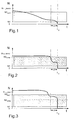
- the rotational speed N of an internal combustion engine is continuously recorded over time t by means of an evaluation unit (not shown here), which is preferably part of an internal combustion engine control unit (cf. FIGS. 1 to 4).
- the course of the speed N is stored for a predetermined moving time window ⁇ t.
- the evaluation unit checks whether the speed N within the time window ⁇ t immediately before the time t 0 of the detection of a standstill of the internal combustion engine is at least partially within a defined speed range N1 to N2 (in general; see hatched areas in FIGS. 1 to 4) or N1 to N2 WARM (Fig. 1, Fig. 2, Fig. 4) or N1 to N2 COLD (Fig. 3). If this is the case, the engine is stalled. If this is not the case, as in the example according to FIG. 4, the internal combustion engine may be stalled. 4, a defective speed sensor or an interruption of the signal line between the speed sensor and the control unit or the evaluation unit is preferably concluded.
- the time t 0 is defined at least by the presence of an "engine stopped” signal. At the same time, the condition “terminal 15 on” could also be required at time t 0 .
- the upper limit N2 WARM of the defined speed band for the warmed-up internal combustion engine is on the one hand lower than the idling speed N LL_WARM , which is assigned to this idling mode in the event of a transition from the current driving state to the idling mode , and on the other hand depends the upper limit N2 WARM from a variable proportional to the engine temperature, here the coolant temperature T K (see also FIG. 5).
- the dependency of the upper limit N2 on the coolant temperature T K is made indirectly by specifying the idle speed N LL , which is already dependent on the engine temperature (N2 WARM is just below N LL_WARM or N2 COLD just below N LL_KALT .)
- the idling speed N LL is first determined at least as a function of the coolant temperature T K. Then the upper limit N2 is set with an offset lower than the idling speed N LL (solid line).
- an error initially recognized at time t 0 using a speed sensor diagnostic method could be deleted again or not saved at all. This prevents incorrect entries in the error memory.
- the speed sensor diagnosis can be tightened with regard to sensitivity.
Landscapes
- Engineering & Computer Science (AREA)
- Chemical & Material Sciences (AREA)
- Combustion & Propulsion (AREA)
- Mechanical Engineering (AREA)
- General Engineering & Computer Science (AREA)
- Combined Controls Of Internal Combustion Engines (AREA)
- Electrical Control Of Air Or Fuel Supplied To Internal-Combustion Engine (AREA)
Abstract
Description
- Fig. 1
- den Verlauf der Drehzahl einer Brennkraftmaschine im Zusammenhang mit dem erfindungsgemäßen Verfahren am Beispiel eines langsamen Abwürgens einer warmgelaufenen Brennkraftmaschine,
- Fig. 2
- den Verlauf der Drehzahl einer Brennkraftmaschine im Zusammenhang mit dem erfindungsgemäßen Verfahren am Beispiel eines schnellen Abwürgens einer warmgelaufenen Brennkraftmaschine,
- Fig. 3
- den Verlauf der Drehzahl einer Brennkraftmaschine im Zusammenhang mit dem erfindungsgemäßen Verfahren am Beispiel eines schnellen Abwürgens einer kalten Brennkraftmaschine
- Fig. 4
- den Verlauf der Drehzahl einer Brennkraftmaschine im Zusammenhang mit dem erfindungsgemäßen Verfahren, nach dem ein defekter Drehzahlsensor anstelle des Abwürgen der Brennkraftmaschine erkannt wird, und
- Fig. 5
- mögliche Abhängigkeitsregeln der oberen Grenze des definierten Drehzahlbereichs sowohl von der Leerlaufdrehzahl als auch von der Brennkraftmaschinentemperatur
Claims (9)
- Verfahren zur Erkennung des Abwürgens einer Brennkraftmaschine mittels einer elektronischen Auswerteeinheit, die zumindest die Drehzahl der Brennkraftmaschine als Eingangssignal erhält, dadurch gekennzeichnet, dass mittels der Auswerteeinheit die Drehzahl (N) kontinuierlich erfasst sowie der Verlauf der Drehzahl (N) zumindest für ein vorgegebenes mitlaufendes Zeitfenster (Δ t) gespeichert wird und dass überprüft wird, ob sich die Drehzahl (N) innerhalb des unmittelbar vor dem Zeitpunkt (t0) der Erkennung eines Stillstandes der Brennkraftmaschine liegenden Zeitfensters (Δt) zumindest teilweise innerhalb eines definierten Drehzahlbandes (N1-N2; N1- N2WARM, N1-N2KALT) befunden hat.
- Verfahren nach Patentanspruch 1, dadurch gekennzeichnet, dass die untere Grenze (N1) des definierten Drehzahlbandes ungleich Null ist.
- Verfahren nach Patentanspruch 1 oder 2, dadurch gekennzeichnet, dass die obere Grenze (N2; N2WARM, N2KALT) des definierten Drehzahlbandes kleiner als die Leerlaufdrehzahl (NLL; NLL_WARM, NLL_KALT) ist, die im Falle eines Überganges vom momentanen Fahrzustand in den Leerlaufbetrieb diesem Leerlaufbetrieb zugeordnet ist.
- Verfahren nach einem der Patentansprüche 1 bis 3, dadurch gekennzeichnet, dass die obere Grenze (N2; N2WARM, N2KALT) des definierten Drehzahlbandes abhängig von einer der Brennkraftmaschinentemperatur proportionalen Größe (TK) ist.
- Steuergerät mit der elektronischen Auswerteeinheit zur Durchführung des Verfahrens nach einem der Patentansprüche 1 bis 4.
- Vorrichtung zur Erkennung des Abwürgens einer Brennkraftmaschine mit einer elektronischen Auswerteeinheit, die zumindest die Drehzahl der Brennkraftmaschine als Eingangssignal erhält, dadurch gekennzeichnet, dass die Auswerteeinheit derart ausgestaltet ist, dass von ihr die Drehzahl (N) kontinuierlich erfasst sowie der Verlauf der Drehzahl (N) zumindest für ein vorgegebenes mitlaufendes Zeitfenster (Δ t) gespeichert wird und dass von ihr überprüft wird, ob sich die Drehzahl (N) innerhalb des unmittelbar vor dem Zeitpunkt (t0) der Erkennung eines Stillstandes der Brennkraftmaschine liegenden Zeitfensters (Δ t) zumindest teilweise innerhalb eines definierten Drehzahlbandes (N1-N2; N1- N2WARM, N1-N2KALT) befunden hat.
- Vorrichtung nach Patentanspruch 6, dadurch gekennzeichnet, dass die untere Grenze (N1) des definierten Drehzahlbandes ungleich Null ist.
- Vorrichtung nach Patentanspruch 6 oder 7, dadurch gekennzeichnet, dass die obere Grenze (N2; N2WARM, N2KALT) des definierten Drehzahlbandes kleiner als die Leerlaufdrehzahl (NLL; NLL_WARM, NLL_KALT) ist, die im Falle eines Überganges vom momentanen Fahrzustand in den Leerlaufbetrieb diesem Leerlaufbetrieb zugeordnet ist.
- Vorrichtung nach einem der Patentansprüche 6 bis 8, dadurch gekennzeichnet, dass die obere Grenze (N2; N2WARM, N2KALT) des definierten Drehzahlbandes abhängig von einer der Brennkraftmaschinentemperatur proportionalen Größe (TK) ist.
Applications Claiming Priority (2)
| Application Number | Priority Date | Filing Date | Title |
|---|---|---|---|
| DE10308507 | 2003-02-26 | ||
| DE2003108507 DE10308507B3 (de) | 2003-02-26 | 2003-02-26 | Verfahren und Vorrichtung zur Erkennung des Abwürgens einer Brennkraftmaschine |
Publications (3)
| Publication Number | Publication Date |
|---|---|
| EP1452847A2 true EP1452847A2 (de) | 2004-09-01 |
| EP1452847A3 EP1452847A3 (de) | 2006-06-07 |
| EP1452847B1 EP1452847B1 (de) | 2007-08-08 |
Family
ID=32731139
Family Applications (1)
| Application Number | Title | Priority Date | Filing Date |
|---|---|---|---|
| EP04003438A Expired - Lifetime EP1452847B1 (de) | 2003-02-26 | 2004-02-16 | Verfahren und Vorrichtung zur Erkennung des Abwürgens einer Brennkraftmaschine |
Country Status (2)
| Country | Link |
|---|---|
| EP (1) | EP1452847B1 (de) |
| DE (2) | DE10308507B3 (de) |
Families Citing this family (2)
| Publication number | Priority date | Publication date | Assignee | Title |
|---|---|---|---|---|
| DE102013214241A1 (de) | 2013-07-22 | 2015-01-22 | Bayerische Motoren Werke Aktiengesellschaft | Vorrichtung zur Optimierung der Gangwechselsteuerung für ein Automatikgetriebe in einem Kraftfahrzeug |
| CN107796620B (zh) * | 2017-10-13 | 2019-09-10 | 重庆长安汽车股份有限公司 | 一种评价整车暖机工况nvh性能的方法 |
Citations (1)
| Publication number | Priority date | Publication date | Assignee | Title |
|---|---|---|---|---|
| DE4434833A1 (de) | 1994-09-29 | 1996-04-04 | Bosch Gmbh Robert | Einrichtung zur Erkennung des Rückdrehens eines rotierenden Teiles einer Brennkraftmaschine |
Family Cites Families (2)
| Publication number | Priority date | Publication date | Assignee | Title |
|---|---|---|---|---|
| JPS6060022B2 (ja) * | 1979-04-16 | 1985-12-27 | 日産自動車株式会社 | 内燃機関制御装置 |
| DE4227113A1 (de) * | 1992-08-17 | 1994-02-24 | Bosch Gmbh Robert | Verfahren zur Fehlererkennung bei der Auswertung der Ausgangssignale eines Drehzahlsensors |
-
2003
- 2003-02-26 DE DE2003108507 patent/DE10308507B3/de not_active Expired - Fee Related
-
2004
- 2004-02-16 DE DE200450004544 patent/DE502004004544D1/de not_active Expired - Lifetime
- 2004-02-16 EP EP04003438A patent/EP1452847B1/de not_active Expired - Lifetime
Patent Citations (1)
| Publication number | Priority date | Publication date | Assignee | Title |
|---|---|---|---|---|
| DE4434833A1 (de) | 1994-09-29 | 1996-04-04 | Bosch Gmbh Robert | Einrichtung zur Erkennung des Rückdrehens eines rotierenden Teiles einer Brennkraftmaschine |
Also Published As
| Publication number | Publication date |
|---|---|
| DE502004004544D1 (de) | 2007-09-20 |
| EP1452847B1 (de) | 2007-08-08 |
| DE10308507B3 (de) | 2004-08-19 |
| EP1452847A3 (de) | 2006-06-07 |
Similar Documents
| Publication | Publication Date | Title |
|---|---|---|
| EP1303691B1 (de) | Verfahren und vorrichtung zur fehlererkennung bzw. diagnose bei einem klopfsensor | |
| DE4328090C2 (de) | Kraftstoffdampfablaßsystem für eine Brennkraftmaschine mit innerer Verbrennung und zugehöriges Diagnoseverfahren | |
| EP1305514B1 (de) | Verfahren zur diagnose der funktionstüchtigkeit eines abgasrückführungssystems einer brennkraftmaschine | |
| DE102004008142A1 (de) | Fehlerdiagnosevorrichtung für einen Motorkühlwassertemperatursensor | |
| WO2004040104A1 (de) | Verfahren zur überprüfung wenigstens dreier sensoren, die eine messgrösse im bereich einer brennkraftmaschine erfassen | |
| EP1622784B1 (de) | Fehlererkennungssytem zur erkennung eines fehlerhaften temperatursensors in kraftfahrzeugen | |
| EP0535183B1 (de) | Verfahren und vorrichtung zum überprüfen der funktionsfähigkeit einer tankentlüftungsanlage | |
| EP1843023A2 (de) | Adaptionsverfahren einer Einspritzanlage einer Brennkraftmaschine | |
| DE10147357B4 (de) | Anlasserschutzeinrichtung | |
| DE60122657T2 (de) | Vorrichtung und Verfahren zur Diagnose eines Kraftstoffversorgungssystems | |
| EP0378627A1 (de) | Fehlfunktions-prüfverfahren und -vorrichtung für leerlaufregelung. | |
| DE102009046417A1 (de) | Verfahren zur Erkennung eines Kraftstoffeintrags in das Schmieröl einer Brennkraftmaschine, insbesondere eines Kraftfahrzeugs | |
| DE102004048136A1 (de) | Verfahren zur Diagnose eines in einem Abgasbereich einer Brennkraftmaschine angeordneten NOx-Sensors und Vorrichtung zur Durchführung des Verfahrens | |
| EP1305513B1 (de) | Verfahren zum überprüfen der funktionstüchtigkeit eines abgasrückführungssystems einer brennkraftmaschine | |
| DE10341454A1 (de) | Verfahren zur Überprüfung wenigstens dreier Sensoren, die eine Messgröße im Bereich einer Brennkraftmaschine erfassen | |
| EP0603543B1 (de) | Verfahren und Vorrichtung zur Überwachung einer Steuereinrichtung einer Brennkraftmaschine | |
| DE10308507B3 (de) | Verfahren und Vorrichtung zur Erkennung des Abwürgens einer Brennkraftmaschine | |
| WO2010015464A1 (de) | Verfahren und steuervorrichtung zum erkennen der drehrichtung einer antriebswelle einer brennkraftmaschine für ein kraftfahrzeug | |
| DE3816207C2 (de) | ||
| DE69912681T2 (de) | Steuerapparat für die Steuerung eines Verbrennungsmotors | |
| EP1311418B1 (de) | Verfahren, computerprogramm und vorrichtung zur überwachung einer unterdruckeinrichtung | |
| DE102010039800A1 (de) | Verfahren und Vorrichtung zur Erkennung des selbständigen Laufens eines Verbrennungsmotors | |
| DE102007006487B4 (de) | Verfahren zur Diagnose eines in einem Abgasbereich einer Brennkraftmaschine angeordneten Abgassensors und Vorrichtung zur Durchführung des Verfahrens | |
| DE10022533B4 (de) | Ausfallsicherungsvorrichtung und Ausfallsicherungsverfahren eines Motors | |
| DE19937154B4 (de) | Verfahren zur saugrohrdruckgeführten geodätische Höhenerkennung bei einem Kraftfahrzeug |
Legal Events
| Date | Code | Title | Description |
|---|---|---|---|
| PUAI | Public reference made under article 153(3) epc to a published international application that has entered the european phase |
Free format text: ORIGINAL CODE: 0009012 |
|
| AK | Designated contracting states |
Kind code of ref document: A2 Designated state(s): AT BE BG CH CY CZ DE DK EE ES FI FR GB GR HU IE IT LI LU MC NL PT RO SE SI SK TR |
|
| AX | Request for extension of the european patent |
Extension state: AL LT LV MK |
|
| PUAL | Search report despatched |
Free format text: ORIGINAL CODE: 0009013 |
|
| AK | Designated contracting states |
Kind code of ref document: A3 Designated state(s): AT BE BG CH CY CZ DE DK EE ES FI FR GB GR HU IE IT LI LU MC NL PT RO SE SI SK TR |
|
| AX | Request for extension of the european patent |
Extension state: AL LT LV MK |
|
| 17P | Request for examination filed |
Effective date: 20061124 |
|
| AKX | Designation fees paid |
Designated state(s): DE FR GB IT |
|
| GRAP | Despatch of communication of intention to grant a patent |
Free format text: ORIGINAL CODE: EPIDOSNIGR1 |
|
| GRAS | Grant fee paid |
Free format text: ORIGINAL CODE: EPIDOSNIGR3 |
|
| GRAA | (expected) grant |
Free format text: ORIGINAL CODE: 0009210 |
|
| AK | Designated contracting states |
Kind code of ref document: B1 Designated state(s): DE FR GB IT |
|
| REG | Reference to a national code |
Ref country code: GB Ref legal event code: FG4D Free format text: NOT ENGLISH |
|
| GBT | Gb: translation of ep patent filed (gb section 77(6)(a)/1977) |
Effective date: 20070821 |
|
| REF | Corresponds to: |
Ref document number: 502004004544 Country of ref document: DE Date of ref document: 20070920 Kind code of ref document: P |
|
| ET | Fr: translation filed | ||
| PLBE | No opposition filed within time limit |
Free format text: ORIGINAL CODE: 0009261 |
|
| 26N | No opposition filed |
Effective date: 20080509 |
|
| PLAA | Information modified related to event that no opposition was filed |
Free format text: ORIGINAL CODE: 0009299DELT |
|
| PLBE | No opposition filed within time limit |
Free format text: ORIGINAL CODE: 0009261 |
|
| D26N | No opposition filed (deleted) | ||
| RIN2 | Information on inventor provided after grant (corrected) |
Inventor name: WAND, JOERG |
|
| 26N | No opposition filed |
Effective date: 20080509 |
|
| PLAA | Information modified related to event that no opposition was filed |
Free format text: ORIGINAL CODE: 0009299DELT |
|
| PLBE | No opposition filed within time limit |
Free format text: ORIGINAL CODE: 0009261 |
|
| STAA | Information on the status of an ep patent application or granted ep patent |
Free format text: STATUS: NO OPPOSITION FILED WITHIN TIME LIMIT |
|
| 26N | No opposition filed |
Effective date: 20080509 |
|
| REG | Reference to a national code |
Ref country code: FR Ref legal event code: PLFP Year of fee payment: 13 |
|
| REG | Reference to a national code |
Ref country code: FR Ref legal event code: PLFP Year of fee payment: 14 |
|
| PGFP | Annual fee paid to national office [announced via postgrant information from national office to epo] |
Ref country code: FR Payment date: 20170220 Year of fee payment: 14 |
|
| PGFP | Annual fee paid to national office [announced via postgrant information from national office to epo] |
Ref country code: GB Payment date: 20170221 Year of fee payment: 14 |
|
| PGFP | Annual fee paid to national office [announced via postgrant information from national office to epo] |
Ref country code: IT Payment date: 20170217 Year of fee payment: 14 |
|
| GBPC | Gb: european patent ceased through non-payment of renewal fee |
Effective date: 20180216 |
|
| REG | Reference to a national code |
Ref country code: FR Ref legal event code: ST Effective date: 20181031 |
|
| PG25 | Lapsed in a contracting state [announced via postgrant information from national office to epo] |
Ref country code: FR Free format text: LAPSE BECAUSE OF NON-PAYMENT OF DUE FEES Effective date: 20180228 Ref country code: GB Free format text: LAPSE BECAUSE OF NON-PAYMENT OF DUE FEES Effective date: 20180216 Ref country code: IT Free format text: LAPSE BECAUSE OF NON-PAYMENT OF DUE FEES Effective date: 20180216 |
|
| PGFP | Annual fee paid to national office [announced via postgrant information from national office to epo] |
Ref country code: DE Payment date: 20230214 Year of fee payment: 20 |
|
| P01 | Opt-out of the competence of the unified patent court (upc) registered |
Effective date: 20230424 |
|
| REG | Reference to a national code |
Ref country code: DE Ref legal event code: R071 Ref document number: 502004004544 Country of ref document: DE |