EP1452467B1 - Unités d'entraînement et assemblages d'entraînement - Google Patents
Unités d'entraînement et assemblages d'entraînement Download PDFInfo
- Publication number
- EP1452467B1 EP1452467B1 EP04075609A EP04075609A EP1452467B1 EP 1452467 B1 EP1452467 B1 EP 1452467B1 EP 04075609 A EP04075609 A EP 04075609A EP 04075609 A EP04075609 A EP 04075609A EP 1452467 B1 EP1452467 B1 EP 1452467B1
- Authority
- EP
- European Patent Office
- Prior art keywords
- rod
- frame member
- recess
- valve
- piston
- Prior art date
- Legal status (The legal status is an assumption and is not a legal conclusion. Google has not performed a legal analysis and makes no representation as to the accuracy of the status listed.)
- Expired - Lifetime
Links
- 230000000712 assembly Effects 0.000 title description 2
- 238000000429 assembly Methods 0.000 title description 2
- 210000002445 nipple Anatomy 0.000 claims abstract description 35
- 230000000295 complement effect Effects 0.000 claims description 8
- 239000012530 fluid Substances 0.000 claims description 4
- 230000006835 compression Effects 0.000 claims description 3
- 238000007906 compression Methods 0.000 claims description 3
- 230000000881 depressing effect Effects 0.000 claims description 2
- 230000004044 response Effects 0.000 claims description 2
- 238000009434 installation Methods 0.000 abstract description 4
- 229910000831 Steel Inorganic materials 0.000 description 5
- 238000010276 construction Methods 0.000 description 5
- 239000010959 steel Substances 0.000 description 5
- 239000000463 material Substances 0.000 description 4
- 230000004308 accommodation Effects 0.000 description 1
- 230000008878 coupling Effects 0.000 description 1
- 238000010168 coupling process Methods 0.000 description 1
- 238000005859 coupling reaction Methods 0.000 description 1
- 230000000994 depressogenic effect Effects 0.000 description 1
- 230000006872 improvement Effects 0.000 description 1
- 239000002184 metal Substances 0.000 description 1
- 239000012260 resinous material Substances 0.000 description 1
Images


Classifications
-
- B—PERFORMING OPERATIONS; TRANSPORTING
- B65—CONVEYING; PACKING; STORING; HANDLING THIN OR FILAMENTARY MATERIAL
- B65G—TRANSPORT OR STORAGE DEVICES, e.g. CONVEYORS FOR LOADING OR TIPPING, SHOP CONVEYOR SYSTEMS OR PNEUMATIC TUBE CONVEYORS
- B65G25/00—Conveyors comprising a cyclically-moving, e.g. reciprocating, carrier or impeller which is disengaged from the load during the return part of its movement
- B65G25/04—Conveyors comprising a cyclically-moving, e.g. reciprocating, carrier or impeller which is disengaged from the load during the return part of its movement the carrier or impeller having identical forward and return paths of movement, e.g. reciprocating conveyors
- B65G25/06—Conveyors comprising a cyclically-moving, e.g. reciprocating, carrier or impeller which is disengaged from the load during the return part of its movement the carrier or impeller having identical forward and return paths of movement, e.g. reciprocating conveyors having carriers, e.g. belts
- B65G25/065—Reciprocating floor conveyors
Definitions
- This invention relates to linear hydraulic drive units and to drive assemblies composed of the linear hydraulic drive units, transverse drive beams and mounting frames, according to the preamble of claim 1.
- Such a drive unit is known from EP 0 721 901.
- the hydraulic drive unit disclosed therein comprises a first bridge beam extending substantially continuously in a transverse direction, which bridge beam is provided with attaching plates 12a and 12b with gates for accommodation therein of parts of the cylinders of the hydraulic drive unit.
- Complementary attaching plates 12c and 12d are bolted against the attaching plates 12a and 12b for clamping the cylinders.
- My U.S. Patent No. Re 35,022, granted August 22, 1995, and entitled Reduced Size Drive/Frame Assembly For Reciprocating Floor Conveyor discloses a drive assembly composed of a small mounting frame, three drive units and three transverse drive beams, one for each drive unit.
- My U.S. Patent No. 5,638,943, granted June 17, 1997 and entitled Drive Assembly For Reciprocating Slat Conveyor discloses a mounting frame that includes a downwardly extending center cavity region for receiving the linear hydraulic drive units.
- My U.S. Patent No. 5,605,221, granted February 25, 1997 discloses a drive assembly (Figs. 32-34) comprising a plurality of drive units, a transverse drive beam for each drive unit, and mounting structure for the drive units.
- Other prior art drive units and mounting structure are disclosed by my U.S. Patent No. 5,353,918, granted October 11, 1994, by U.S. Patent No. 5,263,573, granted November 13, 1993 to Olaf A. Hallstrom, and by European patent application EP 0 721 901 A1, filed by Cargo Handling Systems B.V. on January 15, 1996. All of these patents should be carefully considered for the purpose of putting the present invention into proper perspective relative to the prior art.
- Drive units of the present invention are basically characterized by a hydraulic cylinder connected to a transverse frame member having a downwardly directed recess.
- the hydraulic cylinder has a sidewall forming a piston chamber, a closed end, a rod end, a piston head within the piston chamber, and a piston rod connected to the piston head and extending axially of the hydraulic cylinder out through the rod end of the hydraulic cylinder.
- An end member is provided at the closed end of the hydraulic cylinder.
- the end member has a radial wall portion and a tubular nipple portion that extends axially outwardly from the radial wall portion.
- the radial wall portion includes an outer surface extending radially outwardly from the tubular nipple.
- a removable clamp member is connectable to the frame member.
- the clamp member includes a recess for receiving a portion of the tubular nipple.
- the tubular nipple is received in the recess in the frame member.
- the radial outer surface of the radial wall portion of the end member contiguous a surface of the frame member that borders the recess in the frame member.
- the recess in the removable clamp member receives a portion of the tubular nipple that is not within the recess in the frame member.
- Bolts removably connect the clamp member to the frame member, with the tubular nipple portion of the end member being received in and clamped by and between the recess in the frame member and the recess in the clamp member.
- the tubular nipple includes an axial center opening and a tubular fitting is received within said center opening. The tubular fitting provides a passageway for hydraulic fluid entering into and leaving from the piston chamber at the closed end of the hydraulic
- the tubular fitting includes a valve and a valve operator that extends axially into the piston chamber and includes an inner end portion that is adapted to be contacted by the piston head.
- the piston head When the piston head is retracted into the piston chamber, it contacts the inner end of the valve operator and moves the valve operator outwardly. In response to such movement, the valve operator opens the valve.
- the valve is normally closed when the piston head is not depressing the valve operator.
- the valve includes a valve seat and a valve plug outwardly of the valve seat that is connected to the outer end of the valve operator.
- the valve also includes a compression spring that operates to normally seat the valve plug against the valve seat.
- an outer surface of the tubular nipple, the recess in the transverse frame member and the recess in the removable clamp member have complementary interlocking surfaces which function to prevent axial movement of the hydraulic cylinder relative to the transverse frame member and the removable clamp member.
- the hydraulic cylinder may include a rod-end member having a base, a radial end wall extending upwardly from a portion of said base, and a key extending above another portion of said base and axially from the radial end wall.
- the rod-end member also includes a piston rod opening extending through the key and through a portion of the base.
- the rod-end member further includes a nook above the base and the key. The nook is bounded on one side by the radial end wall.
- the base includes a pair of shoulders, one on each side of the key. A pair of bolt-receiving openings extends through the base and the shoulders.
- a transverse frame member at the rod end of the hydraulic cylinder includes a key-receiving recess adapted to snugly receive the key.
- This frame member includes a side surface that is contiguous the radial end wall of the rod-end member when the key is in the key recess.
- the frame member includes a pair of shoulders, one on each side of the key recess. The frame member shoulders confront the shoulders on the rod-end member when the key is in the key recess and the side surface is contiguous the radial end wall.
- the frame member shoulders have bolt-receiving openings therein that are alignable with the bolt-receiving openings in the rod-end member when the key is within the key recess and the side surface of the frame member is contiguous the radial end wall of the rod-end member.
- Bolts extend through the bolt-receiving openings in the rod-end member and the bolt-receiving openings in said frame-member shoulders. The bolts connect the rod-end member of the hydraulic cylinder to the transverse frame member.
- the piston rod may be provided with a second end portion outside of the cylinder body that is connected to a push rod.
- the piston rod has a convex, substantially spherical end shape.
- the push rod includes a bell-shaped end member having a concave inner end surface substantially conforming to the convex end shape of the piston rod. It also has a convex outer end surface of substantially spherical curvature.
- a coupler is connected to the piston rod axially inwardly of the convex end of the piston rod.
- the coupler includes an annular wall portion surrounding the outer end of the piston rod.
- the annular wall portion has a concave inner surface that substantially conforms to the convex outer surface of the bell-shaped end member on the push-rod.
- At least an end portion of the push rod could be tubular and internally threaded.
- An end member on the push rod member has now complementary external threads that connect to the internal threads in the push-rod.
- the coupler that is attached to the piston-rod is axially split into two halves. Bolts extend between the two halves and secure them together.
- the piston-rod and the two halves of the coupler include interlocking portions where the two halves of the coupler contact the piston-rod. The interlocking portions prevent axial movement of the coupler halves relatively along the piston-rod.
- a unique mounting frame having channel shaped end portions could be provided.
- the linear hydraulic drive unit may comprise: a transverse frame member having a downwardly directed recess; a hydraulic cylinder including a closed end and a rod end, a rod-end member having a base, a radial end wall extending upwardly from a portion of said base, and a key above another portion of said base, said key extending axially from the radial end wall; said rod-end member including a piston rod opening extending through the key and through a portion of the base; said rod-end member further including a nook above the base and the key, said nook being bounded on one side by the radial end wall; said base having a pair of shoulders, one on each side of the key, and a pair of bolt receiving openings extending through the base and the shoulders; said frame member having a key receiving recess adapted to snugly receive the key, and having a side surface that is contiguous the radial end wall of the rod end member when the key is within the key recess; said frame member having a pair of shoulders
- the linear hydraulic drive unit may comprise a second transverse frame member having a downwardly directed recess adjacent the closed end of the hydraulic cylinder; said hydraulic cylinder having an end member at its closed end, said end member having a radial wall portion and da tubular nipple portion extending axially outwardly from the radial wall portion, said radial wall portion including an outer surface extending radially outwardly from the nipple; a removable clamp member connectable to the second frame member, said clamp member including a recess for receiving a portion of tubular nipple; said tubular nipple being received in the recess in the second frame member with the radial outer surface of the radial wall portion of the end member being contiguous a surface of the second frame member bordering the recess in the second frame member; said recess in said removable clamp member receiving a portion of said tubular nipple that is not within the recess in the second frame member; said clamp member having a radial side surface
- the linear hydraulic drive unit may comprise a cylinder body having an open end and a closed end; a piston head inside of said cylinder body; a piston rod having a first end portion connected to the piston head inside the cylinder body, and a second end portion outside of the cylinder body, said piston rod extending from the piston head out through the open end of the cylinder body to its second end portions, said second end portion of said piston rod having a convex, substantially semi-spherical end shape; an elongated push rod; said push rod including a bell shaped end member having a concave inner end surface substantially conforming to the convex end shape on the piston rod, and a convex outer surface of substantially spherical curvature; a coupler connected to the piston rod axially inwardly of the convex end of said piston rod, said coupler including an annular wall portion surrounding the second end portion of the piston rod and having a concave inner surface substantially conforming to the convex outer surface on the bell shaped end member on the push-rod
- the linear hydraulic drive unit may include a push rod end member that has a second end portion that connects to the elongated push rod.
- the linear hydraulic drive unit may include an elongated push rod that has a tubular end portion that is internally threaded and the second end portion of the end member is externally threaded and threads into the end portion of the push rod.
- the linear hydraulic drive unit may include a coupler which is axially split into two halves and bolts extend between the halves and secure them together.
- the linear hydraulic drive unit may include a piston rod and the two halves of the coupler include interlocking portions where the two halves of the coupler contact the piston rod, said interlocking portions preventing axial movement of the coupler halves relatively along the piston rod.
- a drive assembly may have a mounting frame, a plurality of linear hydraulic drive units that are connected to the mounting frame, transverse drive beam connected to each drive unit a transverse mounting member at an end of the mounting frame, and the improvement comprising:
- the lips may extend the full length of the mounting frame.
- the end openings may have closed inner ends and open outer ends, and the web extends inwardly from the inner ends of said openings to the center wall.
- the center wall may have two end portions that are spaced apart, said end portions having lower edges that are connected to the bottom web and extend upwardly to the top of the center member.
- the drive assembly may further include a second transverse mounting member at a second end of the mounting frame, said second transverse mounting member having a center portion and two opposite end portions, the opposite end portions being channel members including a web and top and bottom flanges and the central portion being a channel member comprising a web and top and bottom flanges, wherein the two end portions and the center portions have a common upper flange that extends the full length of the mounting frame member, said center portion has a lower flange that is faced downwardly from the upper flange a predetermined amount, and the end portions have lower flanges which are at a common level and are above the level of the lower flange for the center portion, and the web for the center portion extends outwardly and becomes the webs for the end portions.
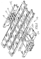
- Figs. 1-14 show a first embodiment of a drive assembly 10 that is constructed in accordance with the present invention. It comprises three drive units, each comprising a linear hydraulic cylinder 12 and a push-rod 14. Each push-rod 14 includes a semi-cylindrical fitting 16 that is welded to the push-rod 14.
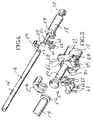
- each linear hydraulic cylinder 12 includes a tubular sidewall 18, a closed end fitting 20 and a rod-end fitting 22. Closed end fitting 20 and closed radial end wall 24 and a tubular nipple 26 connect to the end wall 24 and project axially outwardly from it.
- Each nipple 26 includes an axial center opening 28. Opening 28 is internally threaded. The outer periphery is externally threaded.
- An end fitting 32 has an externally threaded inner end portion 34 that threads into the center opening 28.
- Fitting 32 has a center opening that receives a valve plug 36 that includes a valve operator 38.
- the valve plug 36 is biased towards a valve seat 40 by a spring 42.
- Spring 42 is positioned between the valve plug 36 and an end cap 44.
- End cap 44 includes an externally threaded inner end portion that threads into an internally threaded center opening in the fitting 32.
- the fitting 32 provides a center passageway through which hydraulic fluid flows into and out from the working chamber 46.
- a piston head 48 is located inside of the tubular sidewall 18.
- a piston-rod 50 has an inner end that is connected to the piston-head 48. Piston-rod 50 extends from the piston-head 48 through the center opening 52 in the rod-end member 22. Outside of the piston chamber, the piston-rod 50 extends to an enlarged end member 54. In this embodiment, another end member 56 is connected to the adjacent end of the push-rod 14.
- a two-part clamp 58, 60 serves to connect the two members 54, 56 together. The clamp parts 58, 60 are secured together by a plurality of bolts 62, as shown by Figs. 4 and 5.
- the rod end of member 22 comprises a base 72, a radial wall 64 and a semi-cylindrical key 66.
- the piston-rod 50 extends through an opening 68 that extends through the key 66 and a portion of the base 62.
- a nook 70 is formed above the base 72 and the key 66 and adjacent the wall 64.
- the linear hydraulic motors or cylinders 12 are connected to a transverse mounting frame 74.
- Frame 74 includes a rod-end frame member 76 and a closed end frame member 78.
- Each of these frame members 76, 78 includes a plurality of downwardly opening recesses 80, 82, one for each linear hydraulic motor 12.
- the recesses 80 are sized and shaped to receive the keys 66. When the keys 66 are within the recesses 80, the walls 68 are contiguous the inner surface of the frame member 76. This is shown by Fig. 8, for example.
- Frame member 76 includes bolt-receiving openings 84.
- Frame member 78 includes bolt-receiving openings 86.
- Clamp members 88 are provided for the closed ends of the cylinders 12.
- Each clamp member 88 includes a pair of bolt-receiving openings 90.
- the recesses 82, 92 and the nipples 26 have interlocking portions that serve to prevent movement of the cylinders 12 relative to the mounting frame 72.
- the interlocking portions may be alternating peaks and valleys. The peaks in the recesses 82, 92 fit within valleys formed in the nipples 26. Ridges on the nipples 26 fit in the valleys in the recesses 82, 92.
- Bolts 96 extend through openings 98 (Fig. 5) in the bases 64. The upper ends of the bolts 96 are threaded and they screw into the openings 84 which are internally threaded. When the bolts 96 are tightened, the end members 22 are secured to the frame member 76.
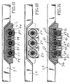
- the bearing blocks 100 are blocks of plastic, preferably, they are constructed from a high molecular weight resinous material referred to as umhw plastic. This material is readily available, is strong, is easily machined to the desired shape, and has exceptionally low surface friction. It is known to be an excellent bearing material.
- umhw plastic a high molecular weight resinous material referred to as umhw plastic. This material is readily available, is strong, is easily machined to the desired shape, and has exceptionally low surface friction. It is known to be an excellent bearing material.
- eight openings 104 are formed in each block 100.
- the same number of openings 106 are formed in a metal cover plate 108. The openings 106 are aligned with the openings 104.
- a bolt 110 extends through a pair of aligned openings 104, 106 and further extends through another opening 112 formed in the web portion 114 of the frame member 102.
- the threaded ends of the bolts 110 pass through the openings 112 and each receives a nut 114, as shown by Fig. 11.
- Bearing blocks 100 are firmly connected to the frame member 102.
- the openings 116 and the bearing blocks 100 are sufficiently long to provide a substantial amount of support for the end portion of the push-rod 14.
- the drive assembly 10 includes three transverse drive beams 124, 126, 128, one for each drive unit.
- the transverse drive beams 124, 126, 128 are connected to the push-rods 14, in a known manner.
- Upper clamp members are secured to the drive beams 124, 126, 128 above the push-rods 14.
- Removable clamps are provided the push-rods 14.
- Bolts are used to connect the lower clamp members to the upper clamp members.
- the members 16 on the push-rods 14 prevent unwanted axial movement of the beams 124, 126, 128 relative to the push-rods 14.
- the members 16 interlock with the upper clamp members on the beams 124, 126, 128 and prevent relative movement in the direction of applied force.
- This concept, including the construction of the members 16, is clearly disclosed in my U.S. Patent No. Re. 35,022, granted August 22, 1995, and entitled “Reduced Size Drive/Frame Assembly For A Reciprocating Floor Conveyor.” See also the structure in my U.S. Patent No. 5,996,774, granted December 7, 1999 and entitled Drive Beam To Drive Unit Connections.
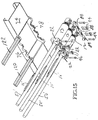
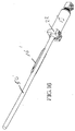
- Figs. 15 and 16 show an embodiment in which the drive units have continuous piston-rods 50'.
- the ends of the rods 50' that are inside of the cylinders 12 are connected to piston-heads within the cylinder bodies, such as in the manner shown by Fig. 8.
- the piston-rod 50' extends outwardly from the piston-head 48 and itself serves as the push-rod.
- Each piston-rod 50' may be a single, continuous member. Or, it may be a continuous member made up of parts that are welded or otherwise connected together.
- Each piston-rod 50' is provided with a member 16' that interlocks with one of the upper clamp members that is attached to the related transverse beam 124, 126, 128. Ribs in valleys or some other suitable structure on the member 16' interlock with complementary ribs and valleys or other structure on the upper clamp parts.
- each drive unit includes a push-rod 14' that is connected to a piston-rod 50".
- the outer end of the piston-rod 50' includes a convex end shape 130 that is of substantially spherical curvature.
- Shape 130 fits into a concave end cavity 132 of complementary curvature. That is, cavity 132 is concave and the curvature is a substantially spherical curvature.
- the cavity 132 is formed in the outer end of a member 134 that has an inner end portion 136 that is cylindrical and is externally threaded.
- the threads 138 mesh with complementary threads 140 that are formed in an end portion of the push-rod 14'.
- the concave surface 132 is a part of a cup-shaped member 142 that has a convex surface 144 on its outside.
- a coupler 146 is attached to the outer end of the piston-rod 50".
- Coupler 146 may be composed of two members, very similar to the members 58, 62 shown in Fig. 5.
- Piston-rod 50" includes circumferentially extending ribs and valleys on its outer end portion that is immediately inwardly of the convex surface 130.
- the members 146, 148 have semi-cylindrical portions with complementary ribs and valleys that engage the ribs and valleys on the piston-rod 50" when the coupler parts 146, 148 are connected together and secured to the piston-rod 50".
- the coupler parts 146, 148 include an annular wall portion that surrounds the cup-shaped end portion on member 134. They have concaved surfaces 152, 154 (Fig. 18) that match the curvature of the surfaces 142, 144. In other words, surfaces 152, 154 have a substantially spherical curvature.
- the surfaces 130, 132, 142, 144, 152, 154 all share the same center of curvature. As a result, there can be universal pivotal movement of the push-rod 14' and the member 134 relative to the piston-rod 50" and the members 146, 148, such pivotal movement occurring about the shared center of curvature.
- the cylinder 12" may be fixed against movement relative to its mounting frame 74 and the outer end of the push-rod 14' may be held for a substantially straight line movement through the bearing blocks 100, while some limited pivotal movement is allowed by the connector between the two rods.
- the end member 22 provides a long bearing support of the piston-rod 50". As a result, the cylinder 12" can withstand substantial side loading imposed by weight on the floor acting on the transverse beam 124 and the push-rod 14'.
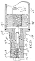
- a fitting 160 fits within an axial socket 162 formed in the nipple 164 that is a part of the end member 166 at the closed end of the cylinder 12".
- Member or fitting 160 includes a valve seat 168 and a valve plug 170 that moves towards and away from the valve seat 168.
- a cup 172 may be provided outwardly of the valve plug 170.
- a compression spring 174 may extend into this cup 172. The opposite end of the spring 174 may make engaging contact with a removable plug 176.
- valve operator 178 is connected to the valve plug 170 on the side thereof opposite the cup 172. Operator 178 extends from the valve plug 170, axially through passageway 180 and the member 160 and at its inner end protrudes into the working chamber 182. When the piston-head 48 and piston-rod 50" are retracted, the side of the piston-head opposite the rod 50" will contact the end of the operator 170. As piston-head 48 moves closer towards the end of the working chamber 182, it moves the operator 178 with it. Operator 178 in turn moves valve plug 170 away from the valve seat 168, opening a fluid passageway between a side port and member 160 and the center passageway 180.
- valve plug 170 When the valve plug 170 is against the valve seat 168, there is communication between side port 182 and passageway 180.
- the valve plug 160 blocks communication between side port 184 and passageway 180.
- valve plug 170 is unseated from the seat 168, there will be communication between side port 184 and passageway 180.
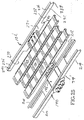
- Figs. 21-25 show a modified frame structure that can be used by any of the above described embodiments.
- the frame structure comprises two transverse mounting frame members 74', 102'.
- the frame members 74, 102 are of a length to be used with a center frame trailer.
- the ends of the frame members 74, 102 are connected to the two longitudinally extending mainframe beams.
- cross-frame members are connected to the ends of the frame members 74, 102.
- These cross-frame members extend outwardly from the ends of the frame members 74, 102 to the sidewall region of the trailer or other installation in which the drive assembly is mounted.
- the two frame members 74', 102' are constructed to include the cells.
- frame member 74' of two-piece construction The pieces or members are designated 190, 192.
- member 190 may be constructed from Swedish steel measuring 3/16 inch thick.
- Member 192 may be constructed from Swedish steel measuring 1 ⁇ 4 inch thick.
- Member 190 is made in the following manner. A flat sheet of material is provided and an opening is cut in it where member 192 is to be added. Also, the openings 196, 198 are made. These openings may be made by cutting the flat sheet of steel by use of a plasma cutting machine. After the flat sheet is cut, it is bent into the shape shown in the drawings.
- the member 74' In the central part of the frame member 74', outwardly on each side of the central cutout 194, the member 74' includes a web 199, a pair of flanges 200, 202 and a pair of lips 204, 206.
- Flanges 200, 202 extend substantially perpendicular to web 199 and lips 204, 206.
- Lips 204, 206 are in coplanar parallelism. Lips 204, 206 are perpendicular to flanges 200, 202 and are parallel to web 198.
- channel beams 208, 210, 212, 214 are formed in the opposite end region which include the cutouts 196, 198, in the web 199.
- the flanges 200, 202 become webs and the lips 204, 206 become flanges.
- the remaining side portions 216, 218, 220, 222 of the web 199 become lower flanges for the beam sections 208, 210, 212, 214.
- Member 192 is cut and then formed into the shape indicated. It is then set into the center cutout 194 and is welded to the inner edges of the web 199 and to the members 204, 206 and the members 200, 202.
- the member 192 forms a downwardly opening compartment in which the central portions of the cylinders are received.
- the frame members 76, 78 are welded to the sides 74' at the location shown in Fig. 3, for example.
- the transverse mounting frame member 102' is also formed from a flat sheet of steel.
- it may be formed from a sheet of Swedish steel that is about 3/6 inch thick. Regions 230, 232 are cut from the sheet and then the sheet is bent to form web 234 and flanges 236, 238, 240.
- the central portion of frame 102 has a channel shape with a deep web.
- the end portions each have a channel shape with a shallower web.
- the lower central portion may extend downwardly between two mainframe beams.
- the end channel 240, 242 first extend outwardly over the tops of the mainframe beams and then continue on to the side of the trailer or other installation in which the drive assembly is mounted.
Landscapes
- Engineering & Computer Science (AREA)
- Mechanical Engineering (AREA)
- Actuator (AREA)
- Control Of Multiple Motors (AREA)
- Power Steering Mechanism (AREA)
Claims (4)
- Unité d'entraînement hydraulique linéaire (10) comprenant :un élément formant châssis transversal (76, 78) ayant un évidement (82) dirigé vers le bas ;un cylindre hydraulique (12) ayant une paroi latérale qui forme une chambre de piston (46), un extrémité fermée, une extrémité côté tige, une tête de piston (48) logée dans la chambre de piston, une tige de piston (14) reliée à la tête de piston et s'étendant dans la direction axiale du cylindre hydraulique en sortant à travers l'extrémité côté tige du cylindre hydraulique ;un élément formant bride amovible (88) pouvant être relié à un élément formant châssis, ledit élément formant bride comprenant un évidement (92) ;des vis (94) qui relient l'élément formant bride (88) à l'élément formant châssis (78) de façon amovible ;un élément d'extrémité (20) situé à l'extrémité fermée du cylindre hydraulique et qui possède une portion formant paroi radiale (24), et une portion formant manchon fileté melon tubulaire (26) qui s'étend axialement vers l'extérieur à partir de la portion formant paroi radiale, ladite portion formant paroi radiale comprenant une surface extérieure qui s'étend radialement vers l'extérieur en partant du manchon fileté ;ledit manchon fileté tubulaire (26) étant reçu dans l'évidement (82) ménagé dans l'élément formant châssis, la surface extérieure radiale de la portion formant paroi radiale de l'élément d'extrémité étant contiguë à une surface de l'élément formant châssis qui borde l'évidement ménagé dans l'élément formant châssis ;ledit évidement (92) ménagé dans ledit élément formant bride amovible recevant une portion dudit manchon fileté tubulaire qui ne se trouve pas dans l'évidement ménagé dans l'élément formant châssis ;ledit élément formant bride ayant une surface latérale radiale qui est contiguë à la surface extérieure de la portion formant paroi radiale dudit élément d'extrémité ;ladite portion formant manchon fileté tubulaire de l'élément d'extrémité étant reçue et serrée par et entre l'évidement (82) ménagé dans l'élément formant châssis et l'évidement (92) ménagé dans l'élément formant bride ;caractérisée en ce que le manchon fileté tubulaire (26) présente une ouverture centrale, et un raccord tubulaire (32) est reçu dans ladite ouverture centrale, ledit raccord tubulaire formant un passage pour un fluide hydraulique qui entre dans la chambre de piston et en sort à l'extrémité fermée du cylindre hydraulique.
- Unité d'entraînement hydraulique linéaire selon revendication 1, caractérisée en ce que le raccord (32) comprend une soupape et un actionneur de soupape (38) qui s'étend axialement en pénétrant dans la chambre de piston (46) et comprend une portion d'extrémité intérieure qui est adaptée pour être attaquée par la tête de piston (48), dans laquelle, lorsque la tête de piston est rétractée dans la chambre de piston, elle attaque l'extrémité intérieure de l'actionneur de soupape et déplace l'actionneur de soupape vers l'extérieur et, en réponse à ce mouvement, l'actionneur de soupape ouvre la soupape, ladite soupape étant normalement fermée lorsque la tête de piston ne repousse pas l'actionneur de soupape.
- Unité d'entraînement hydraulique linéaire selon la revendication 2, caractérisée en ce que la soupape comprend un siège de soupape (40) et un élément mobile de soupape (36) situé à l'extérieur par rapport au siège de soupape et qui est relié à l'extrémité extérieure de l'actionneur de soupape (38), et la soupape comprend aussi un ressort de compression (42) qui a pour effet d'appliquer normalement l'élément mobile de soupape contre le siège de soupape.
- Unité d'entraînement hydraulique linéaire selon la revendication 1, caractérisé en ce qu'une surface extérieure du manchon fileté tubulaire (26), l'évidement (82) ménagé dans ledit élément formant châssis transversal et l'évidement (92) ménagé dans l'élément formant bride amovible ont des surfaces de verrouillage complémentaires qui ont pour fonction d'empêcher le mouvement axial du cylindre hydraulique par rapport à l'élément formant châssis transversal et à l'élément formant bride amovible.
Priority Applications (3)
| Application Number | Priority Date | Filing Date | Title |
|---|---|---|---|
| EP05077352A EP1626015B1 (fr) | 2003-02-26 | 2004-02-25 | Unités d'entraînement et assemblages d'entraînement |
| EP05077350A EP1621487B1 (fr) | 2003-02-26 | 2004-02-25 | Unités d'entraînement et assemblages d'entraînement |
| EP05077351A EP1621488B1 (fr) | 2003-02-26 | 2004-02-25 | Unités d'entraînement et assemblages d'entraînement |
Applications Claiming Priority (2)
| Application Number | Priority Date | Filing Date | Title |
|---|---|---|---|
| US375225 | 1989-07-03 | ||
| US10/375,225 US6994012B2 (en) | 2003-02-26 | 2003-02-26 | Drive units and drive assemblies |
Related Child Applications (3)
| Application Number | Title | Priority Date | Filing Date |
|---|---|---|---|
| EP05077352A Division EP1626015B1 (fr) | 2003-02-26 | 2004-02-25 | Unités d'entraînement et assemblages d'entraînement |
| EP05077351A Division EP1621488B1 (fr) | 2003-02-26 | 2004-02-25 | Unités d'entraînement et assemblages d'entraînement |
| EP05077350A Division EP1621487B1 (fr) | 2003-02-26 | 2004-02-25 | Unités d'entraînement et assemblages d'entraînement |
Publications (2)
| Publication Number | Publication Date |
|---|---|
| EP1452467A1 EP1452467A1 (fr) | 2004-09-01 |
| EP1452467B1 true EP1452467B1 (fr) | 2006-06-07 |
Family
ID=32771455
Family Applications (4)
| Application Number | Title | Priority Date | Filing Date |
|---|---|---|---|
| EP04075609A Expired - Lifetime EP1452467B1 (fr) | 2003-02-26 | 2004-02-25 | Unités d'entraînement et assemblages d'entraînement |
| EP05077351A Expired - Lifetime EP1621488B1 (fr) | 2003-02-26 | 2004-02-25 | Unités d'entraînement et assemblages d'entraînement |
| EP05077352A Expired - Lifetime EP1626015B1 (fr) | 2003-02-26 | 2004-02-25 | Unités d'entraînement et assemblages d'entraînement |
| EP05077350A Expired - Lifetime EP1621487B1 (fr) | 2003-02-26 | 2004-02-25 | Unités d'entraînement et assemblages d'entraînement |
Family Applications After (3)
| Application Number | Title | Priority Date | Filing Date |
|---|---|---|---|
| EP05077351A Expired - Lifetime EP1621488B1 (fr) | 2003-02-26 | 2004-02-25 | Unités d'entraînement et assemblages d'entraînement |
| EP05077352A Expired - Lifetime EP1626015B1 (fr) | 2003-02-26 | 2004-02-25 | Unités d'entraînement et assemblages d'entraînement |
| EP05077350A Expired - Lifetime EP1621487B1 (fr) | 2003-02-26 | 2004-02-25 | Unités d'entraînement et assemblages d'entraînement |
Country Status (6)
| Country | Link |
|---|---|
| US (2) | US6994012B2 (fr) |
| EP (4) | EP1452467B1 (fr) |
| AT (4) | ATE328820T1 (fr) |
| CA (1) | CA2459060A1 (fr) |
| DE (4) | DE602004013963D1 (fr) |
| ES (4) | ES2313202T3 (fr) |
Families Citing this family (6)
| Publication number | Priority date | Publication date | Assignee | Title |
|---|---|---|---|---|
| MXPA05008162A (es) * | 2003-01-30 | 2006-02-17 | Rene Wegkamp | Un motor hidraulico lineal y un transportador de piso alternativo. |
| US7028832B2 (en) * | 2004-09-17 | 2006-04-18 | Keith Investments, Llc | Drive unit mount for reciprocating slat conveyor |
| WO2007054901A1 (fr) * | 2005-11-10 | 2007-05-18 | Rene Wegkamp | Barre d'entrainement |
| CA2630861A1 (fr) * | 2007-05-07 | 2008-11-07 | Hallco Manufacturing Co., Inc. | Transporteur a palettes a mouvement alternatif |
| CN105600316A (zh) * | 2015-12-30 | 2016-05-25 | 天津天瑞达自动化设备有限公司 | 墙体组装用物料传送装置 |
| CN113697393B (zh) * | 2021-08-03 | 2022-12-02 | 广东碧品居建筑工业化有限公司 | 长行程运动模组和输送装置 |
Family Cites Families (14)
| Publication number | Priority date | Publication date | Assignee | Title |
|---|---|---|---|---|
| GB1462120A (en) * | 1974-04-09 | 1977-01-19 | Girling Ltd | Welding apparatus |
| US4071091A (en) * | 1976-06-21 | 1978-01-31 | Caterpillar Tractor Co. | Motor grader with detachable link for reduced blade angle operation |
| US4793469A (en) * | 1983-03-22 | 1988-12-27 | Foster Raymond K | Reduced size drive/frame assembly for a reciprocating floor conveyor |
| US5263573A (en) * | 1990-10-25 | 1993-11-23 | Hallstrom Jr Olof A | Drive connector for reciprocating conveyor |
| US5350054A (en) * | 1993-04-28 | 1994-09-27 | Foster Raymond K | Ball block for mounting linear motor |
| US5605221A (en) * | 1994-09-12 | 1997-02-25 | Foster; Raymond K. | Drive unit with bearing mount |
| NL9500067A (nl) * | 1995-01-13 | 1996-08-01 | Cargo Handling Systems B V | Laadvloer voor vrachtwagens of vrachttrailers. |
| US5638943A (en) * | 1995-11-29 | 1997-06-17 | Foster; Raymond Keith | Drive assembly for reciprocating slat conveyor |
| US5624198A (en) * | 1996-02-06 | 1997-04-29 | Zumtobel Staff Lighting, Inc. | Swivel connector |
| US5911555A (en) * | 1998-05-12 | 1999-06-15 | Foster; Raymond Keith | Vehicle/dock loading/unloading conveyor system |
| US5996774A (en) | 1999-05-28 | 1999-12-07 | Foster; Raymond Keith | Drive beam to drive unit connections |
| US6237965B1 (en) * | 1999-07-27 | 2001-05-29 | Hsien-Wen Kuo | Leak-free flexible conduit |
| US6554834B1 (en) * | 1999-10-07 | 2003-04-29 | Stryker Spine | Slotted head pedicle screw assembly |
| EP1213441B1 (fr) * | 2000-12-06 | 2003-06-11 | Günter Prof. Dr.-Ing. Klemm | Système de forage |
-
2003
- 2003-02-26 US US10/375,225 patent/US6994012B2/en not_active Expired - Fee Related
-
2004
- 2004-02-25 ES ES05077350T patent/ES2313202T3/es not_active Expired - Lifetime
- 2004-02-25 ES ES05077351T patent/ES2303986T3/es not_active Expired - Lifetime
- 2004-02-25 DE DE602004013963T patent/DE602004013963D1/de not_active Expired - Fee Related
- 2004-02-25 AT AT04075609T patent/ATE328820T1/de not_active IP Right Cessation
- 2004-02-25 DE DE602004013960T patent/DE602004013960D1/de not_active Expired - Fee Related
- 2004-02-25 DE DE602004015969T patent/DE602004015969D1/de not_active Expired - Fee Related
- 2004-02-25 AT AT05077352T patent/ATE396128T1/de not_active IP Right Cessation
- 2004-02-25 EP EP04075609A patent/EP1452467B1/fr not_active Expired - Lifetime
- 2004-02-25 ES ES04075609T patent/ES2266977T3/es not_active Expired - Lifetime
- 2004-02-25 ES ES05077352T patent/ES2303987T3/es not_active Expired - Lifetime
- 2004-02-25 EP EP05077351A patent/EP1621488B1/fr not_active Expired - Lifetime
- 2004-02-25 AT AT05077351T patent/ATE396127T1/de not_active IP Right Cessation
- 2004-02-25 AT AT05077350T patent/ATE405506T1/de not_active IP Right Cessation
- 2004-02-25 EP EP05077352A patent/EP1626015B1/fr not_active Expired - Lifetime
- 2004-02-25 DE DE602004001067T patent/DE602004001067T2/de not_active Expired - Fee Related
- 2004-02-25 EP EP05077350A patent/EP1621487B1/fr not_active Expired - Lifetime
- 2004-02-26 CA CA002459060A patent/CA2459060A1/fr not_active Abandoned
-
2005
- 2005-08-29 US US11/213,076 patent/US20050284287A1/en not_active Abandoned
Also Published As
| Publication number | Publication date |
|---|---|
| US20040163530A1 (en) | 2004-08-26 |
| ATE405506T1 (de) | 2008-09-15 |
| DE602004013963D1 (de) | 2008-07-03 |
| ES2303987T3 (es) | 2008-09-01 |
| ES2303986T3 (es) | 2008-09-01 |
| ATE396128T1 (de) | 2008-06-15 |
| EP1621488A1 (fr) | 2006-02-01 |
| ES2313202T3 (es) | 2009-03-01 |
| CA2459060A1 (fr) | 2004-08-26 |
| EP1621487B1 (fr) | 2008-08-20 |
| EP1626015B1 (fr) | 2008-05-21 |
| EP1452467A1 (fr) | 2004-09-01 |
| EP1621487A1 (fr) | 2006-02-01 |
| DE602004001067T2 (de) | 2007-08-02 |
| ATE328820T1 (de) | 2006-06-15 |
| US6994012B2 (en) | 2006-02-07 |
| DE602004001067D1 (de) | 2006-07-20 |
| DE602004013960D1 (de) | 2008-07-03 |
| ES2266977T3 (es) | 2007-03-01 |
| ATE396127T1 (de) | 2008-06-15 |
| US20050284287A1 (en) | 2005-12-29 |
| DE602004015969D1 (de) | 2008-10-02 |
| EP1621488B1 (fr) | 2008-05-21 |
| EP1626015A1 (fr) | 2006-02-15 |
Similar Documents
| Publication | Publication Date | Title |
|---|---|---|
| US4821868A (en) | Drive/frame assembly for a reciprocating floor | |
| US4748893A (en) | Drive/frame assembly for a reciprocating floor | |
| EP1452467B1 (fr) | Unités d'entraînement et assemblages d'entraînement | |
| US4748894A (en) | Drive/frame assembly for a reciprocating floor | |
| EP0259900B1 (fr) | Moteur linéaire hydraulique et valve de transfert combinés | |
| WO2007084639A2 (fr) | Bande transporteuse à lattes écartées comprenant des lattes de transport et des lattes de levage | |
| US6003660A (en) | Drive units and drive assembly for a reciprocating slat conveyors | |
| US5638943A (en) | Drive assembly for reciprocating slat conveyor | |
| IT8520051A1 (it) | Unita' a pistone | |
| US6056113A (en) | Drive beam to drive unit connections | |
| EP0728688B1 (fr) | Système pour monter un transporteur à lattes avec mouvement va-et-vient | |
| US7584838B2 (en) | Linear hydraulic motor and a reciprocating floor conveyor | |
| US7661523B2 (en) | Linear hydraulic motor and reciprocating floor conveyor | |
| US20090107807A1 (en) | Reciprocating Floor | |
| US7658276B2 (en) | Drive beam | |
| CA1329534C (fr) | Bloc bati/entrainement pour plancher rotatif |
Legal Events
| Date | Code | Title | Description |
|---|---|---|---|
| PUAI | Public reference made under article 153(3) epc to a published international application that has entered the european phase |
Free format text: ORIGINAL CODE: 0009012 |
|
| AK | Designated contracting states |
Kind code of ref document: A1 Designated state(s): AT BE BG CH CY CZ DE DK EE ES FI FR GB GR HU IE IT LI LU MC NL PT RO SE SI SK TR |
|
| AX | Request for extension of the european patent |
Extension state: AL HR LT LV MK |
|
| 17P | Request for examination filed |
Effective date: 20050217 |
|
| AKX | Designation fees paid |
Designated state(s): AT BE BG CH CY CZ DE DK EE ES FI FR GB GR HU IE IT LI LU MC NL PT RO SE SI SK TR |
|
| AXX | Extension fees paid |
Extension state: AL Payment date: 20050217 Extension state: LT Payment date: 20050217 Extension state: LV Payment date: 20050217 Extension state: MK Payment date: 20050217 |
|
| 17Q | First examination report despatched |
Effective date: 20050602 |
|
| GRAP | Despatch of communication of intention to grant a patent |
Free format text: ORIGINAL CODE: EPIDOSNIGR1 |
|
| GRAS | Grant fee paid |
Free format text: ORIGINAL CODE: EPIDOSNIGR3 |
|
| GRAA | (expected) grant |
Free format text: ORIGINAL CODE: 0009210 |
|
| AK | Designated contracting states |
Kind code of ref document: B1 Designated state(s): AT BE BG CH CY CZ DE DK EE ES FI FR GB GR HU IE IT LI LU MC NL PT RO SE SI SK TR |
|
| AX | Request for extension of the european patent |
Extension state: AL LT LV MK |
|
| PG25 | Lapsed in a contracting state [announced via postgrant information from national office to epo] |
Ref country code: IT Free format text: LAPSE BECAUSE OF FAILURE TO SUBMIT A TRANSLATION OF THE DESCRIPTION OR TO PAY THE FEE WITHIN THE PRESCRIBED TIME-LIMIT;WARNING: LAPSES OF ITALIAN PATENTS WITH EFFECTIVE DATE BEFORE 2007 MAY HAVE OCCURRED AT ANY TIME BEFORE 2007. THE CORRECT EFFECTIVE DATE MAY BE DIFFERENT FROM THE ONE RECORDED. Effective date: 20060607 Ref country code: AT Free format text: LAPSE BECAUSE OF FAILURE TO SUBMIT A TRANSLATION OF THE DESCRIPTION OR TO PAY THE FEE WITHIN THE PRESCRIBED TIME-LIMIT Effective date: 20060607 Ref country code: LI Free format text: LAPSE BECAUSE OF FAILURE TO SUBMIT A TRANSLATION OF THE DESCRIPTION OR TO PAY THE FEE WITHIN THE PRESCRIBED TIME-LIMIT Effective date: 20060607 Ref country code: CZ Free format text: LAPSE BECAUSE OF FAILURE TO SUBMIT A TRANSLATION OF THE DESCRIPTION OR TO PAY THE FEE WITHIN THE PRESCRIBED TIME-LIMIT Effective date: 20060607 Ref country code: FI Free format text: LAPSE BECAUSE OF FAILURE TO SUBMIT A TRANSLATION OF THE DESCRIPTION OR TO PAY THE FEE WITHIN THE PRESCRIBED TIME-LIMIT Effective date: 20060607 Ref country code: CH Free format text: LAPSE BECAUSE OF FAILURE TO SUBMIT A TRANSLATION OF THE DESCRIPTION OR TO PAY THE FEE WITHIN THE PRESCRIBED TIME-LIMIT Effective date: 20060607 Ref country code: RO Free format text: LAPSE BECAUSE OF FAILURE TO SUBMIT A TRANSLATION OF THE DESCRIPTION OR TO PAY THE FEE WITHIN THE PRESCRIBED TIME-LIMIT Effective date: 20060607 Ref country code: SK Free format text: LAPSE BECAUSE OF FAILURE TO SUBMIT A TRANSLATION OF THE DESCRIPTION OR TO PAY THE FEE WITHIN THE PRESCRIBED TIME-LIMIT Effective date: 20060607 Ref country code: SI Free format text: LAPSE BECAUSE OF FAILURE TO SUBMIT A TRANSLATION OF THE DESCRIPTION OR TO PAY THE FEE WITHIN THE PRESCRIBED TIME-LIMIT Effective date: 20060607 |
|
| REG | Reference to a national code |
Ref country code: GB Ref legal event code: FG4D |
|
| REG | Reference to a national code |
Ref country code: CH Ref legal event code: EP |
|
| REG | Reference to a national code |
Ref country code: IE Ref legal event code: FG4D |
|
| REF | Corresponds to: |
Ref document number: 602004001067 Country of ref document: DE Date of ref document: 20060720 Kind code of ref document: P |
|
| PG25 | Lapsed in a contracting state [announced via postgrant information from national office to epo] |
Ref country code: DK Free format text: LAPSE BECAUSE OF FAILURE TO SUBMIT A TRANSLATION OF THE DESCRIPTION OR TO PAY THE FEE WITHIN THE PRESCRIBED TIME-LIMIT Effective date: 20060907 Ref country code: SE Free format text: LAPSE BECAUSE OF FAILURE TO SUBMIT A TRANSLATION OF THE DESCRIPTION OR TO PAY THE FEE WITHIN THE PRESCRIBED TIME-LIMIT Effective date: 20060907 |
|
| PG25 | Lapsed in a contracting state [announced via postgrant information from national office to epo] |
Ref country code: PT Free format text: LAPSE BECAUSE OF FAILURE TO SUBMIT A TRANSLATION OF THE DESCRIPTION OR TO PAY THE FEE WITHIN THE PRESCRIBED TIME-LIMIT Effective date: 20061107 |
|
| LTIE | Lt: invalidation of european patent or patent extension |
Effective date: 20060607 |
|
| ET | Fr: translation filed | ||
| REG | Reference to a national code |
Ref country code: CH Ref legal event code: PL |
|
| PG25 | Lapsed in a contracting state [announced via postgrant information from national office to epo] |
Ref country code: MC Free format text: LAPSE BECAUSE OF NON-PAYMENT OF DUE FEES Effective date: 20070228 |
|
| REG | Reference to a national code |
Ref country code: ES Ref legal event code: FG2A Ref document number: 2266977 Country of ref document: ES Kind code of ref document: T3 |
|
| PLBE | No opposition filed within time limit |
Free format text: ORIGINAL CODE: 0009261 |
|
| STAA | Information on the status of an ep patent application or granted ep patent |
Free format text: STATUS: NO OPPOSITION FILED WITHIN TIME LIMIT |
|
| 26N | No opposition filed |
Effective date: 20070308 |
|
| PG25 | Lapsed in a contracting state [announced via postgrant information from national office to epo] |
Ref country code: IE Free format text: LAPSE BECAUSE OF NON-PAYMENT OF DUE FEES Effective date: 20070226 |
|
| PG25 | Lapsed in a contracting state [announced via postgrant information from national office to epo] |
Ref country code: GR Free format text: LAPSE BECAUSE OF FAILURE TO SUBMIT A TRANSLATION OF THE DESCRIPTION OR TO PAY THE FEE WITHIN THE PRESCRIBED TIME-LIMIT Effective date: 20060908 |
|
| PGFP | Annual fee paid to national office [announced via postgrant information from national office to epo] |
Ref country code: ES Payment date: 20080229 Year of fee payment: 5 |
|
| PGFP | Annual fee paid to national office [announced via postgrant information from national office to epo] |
Ref country code: GB Payment date: 20080304 Year of fee payment: 5 Ref country code: IT Payment date: 20080227 Year of fee payment: 5 |
|
| PG25 | Lapsed in a contracting state [announced via postgrant information from national office to epo] |
Ref country code: BG Free format text: LAPSE BECAUSE OF FAILURE TO SUBMIT A TRANSLATION OF THE DESCRIPTION OR TO PAY THE FEE WITHIN THE PRESCRIBED TIME-LIMIT Effective date: 20060907 |
|
| PG25 | Lapsed in a contracting state [announced via postgrant information from national office to epo] |
Ref country code: EE Free format text: LAPSE BECAUSE OF FAILURE TO SUBMIT A TRANSLATION OF THE DESCRIPTION OR TO PAY THE FEE WITHIN THE PRESCRIBED TIME-LIMIT Effective date: 20060607 |
|
| PGFP | Annual fee paid to national office [announced via postgrant information from national office to epo] |
Ref country code: BE Payment date: 20080304 Year of fee payment: 5 |
|
| PGFP | Annual fee paid to national office [announced via postgrant information from national office to epo] |
Ref country code: NL Payment date: 20090331 Year of fee payment: 6 |
|
| BERE | Be: lapsed |
Owner name: *KEITH INVESTMENTS LLC Effective date: 20090228 |
|
| PG25 | Lapsed in a contracting state [announced via postgrant information from national office to epo] |
Ref country code: LU Free format text: LAPSE BECAUSE OF NON-PAYMENT OF DUE FEES Effective date: 20070225 Ref country code: CY Free format text: LAPSE BECAUSE OF FAILURE TO SUBMIT A TRANSLATION OF THE DESCRIPTION OR TO PAY THE FEE WITHIN THE PRESCRIBED TIME-LIMIT Effective date: 20060607 |
|
| PGFP | Annual fee paid to national office [announced via postgrant information from national office to epo] |
Ref country code: DE Payment date: 20090330 Year of fee payment: 6 Ref country code: FR Payment date: 20090327 Year of fee payment: 6 |
|
| PG25 | Lapsed in a contracting state [announced via postgrant information from national office to epo] |
Ref country code: TR Free format text: LAPSE BECAUSE OF FAILURE TO SUBMIT A TRANSLATION OF THE DESCRIPTION OR TO PAY THE FEE WITHIN THE PRESCRIBED TIME-LIMIT Effective date: 20060607 Ref country code: HU Free format text: LAPSE BECAUSE OF FAILURE TO SUBMIT A TRANSLATION OF THE DESCRIPTION OR TO PAY THE FEE WITHIN THE PRESCRIBED TIME-LIMIT Effective date: 20061208 |
|
| GBPC | Gb: european patent ceased through non-payment of renewal fee |
Effective date: 20090225 |
|
| PG25 | Lapsed in a contracting state [announced via postgrant information from national office to epo] |
Ref country code: BE Free format text: LAPSE BECAUSE OF NON-PAYMENT OF DUE FEES Effective date: 20090228 |
|
| REG | Reference to a national code |
Ref country code: ES Ref legal event code: FD2A Effective date: 20090226 |
|
| PG25 | Lapsed in a contracting state [announced via postgrant information from national office to epo] |
Ref country code: GB Free format text: LAPSE BECAUSE OF NON-PAYMENT OF DUE FEES Effective date: 20090225 |
|
| PG25 | Lapsed in a contracting state [announced via postgrant information from national office to epo] |
Ref country code: ES Free format text: LAPSE BECAUSE OF NON-PAYMENT OF DUE FEES Effective date: 20090226 |
|
| REG | Reference to a national code |
Ref country code: NL Ref legal event code: V1 Effective date: 20100901 |
|
| REG | Reference to a national code |
Ref country code: FR Ref legal event code: ST Effective date: 20101029 |
|
| PG25 | Lapsed in a contracting state [announced via postgrant information from national office to epo] |
Ref country code: NL Free format text: LAPSE BECAUSE OF NON-PAYMENT OF DUE FEES Effective date: 20100901 Ref country code: FR Free format text: LAPSE BECAUSE OF NON-PAYMENT OF DUE FEES Effective date: 20100301 |
|
| PG25 | Lapsed in a contracting state [announced via postgrant information from national office to epo] |
Ref country code: DE Free format text: LAPSE BECAUSE OF NON-PAYMENT OF DUE FEES Effective date: 20100901 |
|
| PG25 | Lapsed in a contracting state [announced via postgrant information from national office to epo] |
Ref country code: IT Free format text: LAPSE BECAUSE OF NON-PAYMENT OF DUE FEES Effective date: 20090225 |