EP1452276B1 - Fastener holding device - Google Patents
Fastener holding device Download PDFInfo
- Publication number
- EP1452276B1 EP1452276B1 EP04100747A EP04100747A EP1452276B1 EP 1452276 B1 EP1452276 B1 EP 1452276B1 EP 04100747 A EP04100747 A EP 04100747A EP 04100747 A EP04100747 A EP 04100747A EP 1452276 B1 EP1452276 B1 EP 1452276B1
- Authority
- EP
- European Patent Office
- Prior art keywords
- holding device
- gripping
- gripping elements
- guide
- fastener
- Prior art date
- Legal status (The legal status is an assumption and is not a legal conclusion. Google has not performed a legal analysis and makes no representation as to the accuracy of the status listed.)
- Expired - Lifetime
Links
- 230000005540 biological transmission Effects 0.000 claims description 17
- 230000037431 insertion Effects 0.000 claims 2
- 238000003780 insertion Methods 0.000 claims 2
- 230000036316 preload Effects 0.000 claims 1
- 238000010276 construction Methods 0.000 description 3
- 238000000034 method Methods 0.000 description 3
- 238000007789 sealing Methods 0.000 description 3
- 210000000078 claw Anatomy 0.000 description 2
- 238000006073 displacement reaction Methods 0.000 description 2
- 239000002184 metal Substances 0.000 description 2
- 238000003825 pressing Methods 0.000 description 2
- ATJFFYVFTNAWJD-UHFFFAOYSA-N Tin Chemical compound [Sn] ATJFFYVFTNAWJD-UHFFFAOYSA-N 0.000 description 1
- 230000006978 adaptation Effects 0.000 description 1
- 230000007797 corrosion Effects 0.000 description 1
- 238000005260 corrosion Methods 0.000 description 1
- 238000005553 drilling Methods 0.000 description 1
- 230000002349 favourable effect Effects 0.000 description 1
- 238000002347 injection Methods 0.000 description 1
- 239000007924 injection Substances 0.000 description 1
- 238000007689 inspection Methods 0.000 description 1
- 238000009434 installation Methods 0.000 description 1
- 239000000463 material Substances 0.000 description 1
- 230000000750 progressive effect Effects 0.000 description 1
- 238000010079 rubber tapping Methods 0.000 description 1
- 239000007779 soft material Substances 0.000 description 1
- 239000000243 solution Substances 0.000 description 1
Images


Classifications
-
- B—PERFORMING OPERATIONS; TRANSPORTING
- B25—HAND TOOLS; PORTABLE POWER-DRIVEN TOOLS; MANIPULATORS
- B25B—TOOLS OR BENCH DEVICES NOT OTHERWISE PROVIDED FOR, FOR FASTENING, CONNECTING, DISENGAGING OR HOLDING
- B25B23/00—Details of, or accessories for, spanners, wrenches, screwdrivers
- B25B23/02—Arrangements for handling screws or nuts
- B25B23/08—Arrangements for handling screws or nuts for holding or positioning screw or nut prior to or during its rotation
- B25B23/10—Arrangements for handling screws or nuts for holding or positioning screw or nut prior to or during its rotation using mechanical gripping means
-
- B—PERFORMING OPERATIONS; TRANSPORTING
- B23—MACHINE TOOLS; METAL-WORKING NOT OTHERWISE PROVIDED FOR
- B23P—METAL-WORKING NOT OTHERWISE PROVIDED FOR; COMBINED OPERATIONS; UNIVERSAL MACHINE TOOLS
- B23P19/00—Machines for simply fitting together or separating metal parts or objects, or metal and non-metal parts, whether or not involving some deformation; Tools or devices therefor so far as not provided for in other classes
- B23P19/001—Article feeders for assembling machines
- B23P19/006—Holding or positioning the article in front of the applying tool
Definitions
- the invention relates to a holding device for holding fasteners, such as screws, which can be fixed to a screwdriver and with a Swissfardes a fastening means, which can be used, for example, from a front side of the screwing ago in a tool bit, is additionally supported, wherein the holding device at least two gripping elements which can be applied in a support position on a shaft of the fastening means and which can be laid by a force application in a release position in which they are spaced from the shaft.
- fasteners such as screws
- a fastening means which can be used, for example, from a front side of the screwing ago in a tool bit
- Such holding devices allow an automatic holding of the fastening means on the screwdriver and thereby facilitate the screwing considerably.
- such holding devices are very advantageous because they support the screws radially and thereby wobble the screws and resulting damage avoid on the surfaces.
- a time-consuming predrilling can be dispensed with in many cases. Overall, the screwing process is thus simplified by the holding devices and damage to the assembly workpieces avoided.
- a screwdriver with a screw holding means which has two claws respectively arranged at the end of a pivoting arm for temporarily holding a screw.
- the pivot arms are mounted on a sleeve, which in turn is mounted on an inner further sleeve. If a screw is screwed into a workpiece with the screwdriver, then this is first held over the two claws. With progressive screwing in the screw, the inner sleeve presses with the located at its end facing the screw from the inside against the pivot arms and spreads them, the screw is released.
- DE 40 37 547 shows a device for mounting screws, which is fixed via a sleeve-shaped component to a screwdriver.
- a likewise sleeve-shaped support member is guided telescopically on the component and carries two, each rotatable about a pin gripping elements in the form of holding jaws which protrude in the rest position approximately perpendicular to the inner wall of the support member inwardly while supporting the shank of a screw with their free ends.
- the front side of the supporting part which is in the working direction, comes into contact with the workpiece into which the screw is driven.
- the support member is moved by the back pressure of the workpiece relative to the component and with respect to the screw. This is the screw head in contact with the holding jaws, which pivots out of the drive path of the screw in the direction of the workpiece.
- the holding jaws To ensure that the screw can be driven into the workpiece as far as it will go, it is necessary here for the holding jaws to be moved completely behind the end face of the tool bit in the driving direction.
- the known approach has the disadvantage that, among other things, the entire length of the holding jaws must be kept as a shift length of the support member relative to the component. As a consequence, it is necessary to connect the spindle of the screwdriver via a special extension with the tool bit or to use a specially shaped, long tool bit. This will incur additional costs.
- the present invention has for its object to provide a holding device for screws, which avoids the aforementioned disadvantages and has a simple construction of short length.
- the gripping elements come into contact with the workpiece, in which the fastener is driven.
- the force is applied to the laying of the gripping elements in the release position directly through the workpiece.
- the length of the holding device can be shortened with a simple design.
- a secure and timely actuation of the gripping elements is ensured by the direct loading of the gripping elements by the workpiece.
- the at least one contact region is formed by at least one roller.
- rollers on the one hand a low-friction radial movement of the gripping elements on the workpiece surface in relation to Eintreibachse allows, which reduces the force required in the operation of the gripping device.
- scratch marks or other damage to the workpiece can be avoided, especially if the rollers have at least on their lateral surface a soft material such as rubber or soft plastic.
- the roller is spherically shaped. This avoids that the rollers, especially in an oblique placement of the holding device on a workpiece surface, cause Eindschreibspuren by roller edges.
- the gripping elements are formed by gripping arms, which are held on the one hand via a pivot bearing, which is axially displaceable relative to a transmission part of the screwing in the driving direction.
- the storage of the gripping arms takes place via a link guide.
- Both the axial and the radial path component is performed by a uniform movement of the gripping elements, whereby the overall structure of the holding device can be greatly simplified.
- a relatively filigree structure can be achieved by the use of gripping arms, which ensures a low weight of the holding device and a good inspection of the fastener to be driven.
- the link guide has at least one curved guide recess, for example in the form of an elongated hole or a groove, on the respective gripper element.
- this guide recess protrudes a guide element which is connected immovably to the transmission part.
- the guide recess is most curved toward a first end on which the guide element is placed when the gripping elements are in the support position.
- the first end is formed by a straight end portion and this end portion is aligned in the support position of the holding device substantially parallel to the driving direction.
- the gripping elements are kept securely closed during the screwing, as long as the contact area has not yet come to the respective workpiece in plant.
- an accidental opening of the holding device for example, due to vibrations that occur during the screwing avoided.
- the guide recess has a straight section towards a second end, on which the guide element is placed, when the gripping elements are in the release position.
- lateral forces are avoided within the gripping elements, whereby a slimmer shape of the gripping elements is possible.
- the holding device has a latching device.
- the gripping elements can be locked in a predetermined locking position.
- a small additional force is required in the form of additional pressure between the contact region of the gripping elements and the workpiece. This makes it possible to predetermine an exact position of the gripping elements in the support position. In addition, the risk of accidental opening of the gripping device is reduced.
- the predetermined locking position of the latching device is adjustable. This makes it possible to adjust the position of the gripping elements in the support position to different shaft diameter of the fasteners to be driven.
- the locking device is formed by a relative to the transmission part in different positions fixable locking receiving element on which a sliding element is guided along, which carries the pivot bearing of the gripping elements and against the transmission part is axially displaceable.
- the latch receiving element has a recess. In this recess engages in the supporting position of the gripping elements a locking element which is displaceably held on the sliding element and biased in the direction of the locking receiving element.
- the gripping elements are biased in the release position.
- the gripping elements are guided josststieri in the release position and thus the contact area of the gripping elements are moved in the driving direction behind the bit end face of the tool bits as soon as the locking device is released from the support position.
- unnecessary contact between the gripping elements and the workpiece and thereby possible damage such as scratches on the workpiece is avoided.
- the bias is effected by a helical spring which sits on the detent element and is arranged between the sliding element and the gear part, or a component fixed thereto.
- the locking receiving element is additionally used as a guide for the biasing spring, whereby additional components can be saved.
- a gripping jaw is arranged on at least one gripping element in a region which can be placed against the shank of the fastening means.
- the gripping element also has a resilient region, for example in the form of an integrated leaf spring. Due to the resilient region, when the holding device is brought into the supporting position, an automatic adaptation of the gripping arms to the respective shaft diameter takes place. On a manual adjustment of the locking device can thus be dispensed with.
- the spring portion is formed so that it in conjunction with the straight end portion of an additional or own locking function in the support position takes over. In this way, if necessary, can be dispensed with the locking device.
- the jaw is releasably connected to the rest of the gripping element. This makes it possible to replace a gripping jaw, which shows signs of wear, without having to replace the entire gripping element.
- the jaw on a wedge-shaped recess ensures that each gripping element bears on the shaft of the fastener to be driven in via two contact lines, regardless of the diameter of the shank. In this way, a secure guidance of the shaft can be ensured by the gripping elements.
- a tool bit which has a clamping device.
- this clamping device egg n friction engagement between the tool bit and the head of the fastener is generated when inserting a fastener in the holding device.
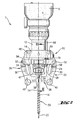
- a transmission part 4 which has a transmission housing 6.
- the transmission part 4 has an attachment end 8 (see Fig. 3 ), on which a holding device 10 is mounted via a carrier sleeve 12.
- a sliding element 14 is slidably mounted along a driving axis 16.
- two pivot bearings 18 are carried out, via which in each case a gripping arm formed as a gripping member 20 is rotatably mounted with its rear in the driving direction 22 opposite the sliding element 14 and the transmission part 4.
- each have a guide recess 24 is formed in the form of a curved elongated hole.
- the guide recess 24 is strongly curved towards a first end 26.
- the guide recess 24 has a straight section 30.
- a guide element 32 in the form of a pin.
- Both guide elements are arranged on a support member 34 which is fixedly mounted on a front in the driving direction 22 of the support sleeve 12. Both guide recesses 24 form in this way with the respective guide element 32 a slotted guide.
- both gripping elements 20 On the side facing away from the pivot bearing 18 respective end of both gripping elements 20, these each have a jaw receptacle 36 in which a gripping jaw 38 is releasably attached.
- both gripping elements 20 in the extension of the straight portion 30 of the guide recess 24 each have a roller 40 which is rotatably mounted on the respective gripping element 20.
- a spindle end 42 of the screwdriver 2 out.
- a bit holder 44 is formed, in which a tool bit 46 is used.
- a depth stop 47 is screwed into the carrier sleeve 12, which can also be removed as needed.
- the tool bit 46 again has a hexagonal receptacle 48 in the drive-in direction 22, to which a fastening means 50 in the form of a screw is inserted.
- a spring-loaded ball 52 is made on the tool bit 46, which is pressed into the hexagonal receptacle 48 through a lateral opening.
- the ball 52 presses against a hexagonal head 54 of the fastener 50, which is positioned in the inserted state of the fastener 50 in the hexagonal receptacle 48, and clamped in this way the fastener 50 to the tool bit 46.
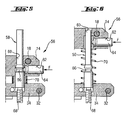
- a detent device 56 shown in more detail, having a detent receiving element 58 in the form of a pin which is clamped on the support member 34 and projects into a guide hole 60 or passes through this, which is formed on the sliding element 14.
- a receiving bore 62 Transverse to the guide bore 60, a receiving bore 62 is formed, which is open to the guide bore 60 back.
- a locking element 64 is arranged, which is biased in the direction of the guide bore 60 by a spring force F shown only schematically.
- Fig. 5 shows the latching device 56 in a latching position, which corresponds to the supporting position of the gripping elements 20.
- the latching element 64 protrudes into a recess 66 in the form of a constriction, which is formed on the latch receiving element 58.
- the sliding element 14 is held with respect to the support member 34 at a predetermined distance.
- a set screw 68 is provided on the support member 34 facing the end of the locking receiving element 58.
- a set screw 68 is provided on the support member 34 facing the end of the locking receiving element 58.
- a coil spring 70 is guided on the latch receiving element 58, which pushes the sliding element 14 away from the support element 34.
- the release position ( Fig. 6 ) occupies, in which the gripping elements 20 are opened.
- a fastener 50 with its hexagonal head 54 can be freely inserted from the front of the screwdriver 2 in the tool bit 46.
- the spring-loaded ball 52 prevents unwanted falling out of the fastener 50 from the tool bit 46th
- the operator therefore has both hands free, on the one hand to hold the screwdriver 2 and on the other hand push the sliding element 14 against the spring force of the coil spring 70 in the direction of the support member 34 until the locking element 64 as in Fig. 5 shown engages in the recess 66.
- the holding device 10 now takes in the Fig. 2 and 4 shown support position in which the coil spring 70 is biased.
- the jaws 38 of the gripping elements 20 are below the hexagonal head 54 and a sealing washer 72 on a shaft 74 of the fastener 50 at.
- the gripping jaws 38 are prism-shaped with a triangular in cross-section recess 39 and are characterized in each case via two lines of contact on the shaft 74 at.
- the distance between the two jaws 38 in the support position on the adjusting screw 68 of the latching device 56 can be accurately adjusted .
- the operator sets the distance between the sliding element 14 and the support element 34 and thus also the contact point of the guide element 32 on the guide recess 24 in the support position via the adjusting screw 68.
- the distance between the gripping jaws 38 is determined, which serves as a guide region for the shaft 74 in the support position. The operator will usually choose this distance so that the gripping jaws 38 rest in the support position just without play on the shaft 74.
- gripping jaws 38 are also possible optionally to use gripping jaws 38 with different shapes. For example, instead of the illustrated gripping jaws 38 with a triangular recess, gripping jaws with a round recess could also be selected in order to achieve improved guidance of the shaft 74.
- the screwdriver 2 is turned on and driven the fastener 50 in driving direction 22 in the workpiece, not shown.
- the gripping elements 20 support the shaft 74 in the radial direction and thus ensure safe guidance even with a large length of the fastening means 50.
- the fastening means 50 can therefore be driven without pre-drilling tumble-free in the workpiece.
- the strongly curved part of the guide recesses 24 of the gripper elements 20 is moved along the guide element 32.
- This ensures simultaneously with the axial movement of the gripping elements 20 along the driving axis 16 for a rapid pivoting of the gripping elements 20 about the respective pivot bearing 18 and thus for a pronounced radial spacing of the gripping jaws 38 from each other.
- these are displaced along the straight section 30 substantially parallel to the drive-in axis 16 and thus by the shortest path to the rear.
- the distance between the jaws 38 is already so large that they can be moved against the driving direction 22 on the sealing disc 72 and placed next to the depth stop 47 and the tool bit 46.
- the frictional engagement between the spring-loaded ball 52 and the hexagonal head 54 of the fastening means 50 is overcome by slight pulling on the screwdriver 2 against the driving-in direction 22 and the screwdriver 2 is separated from the fastening means 50.
- the coil spring 70 holds the holding device 10 in the release position according to Fig. 1 ,
- a new fastener 50 can be inserted from the considered in relation to the driving direction 22 front of the screwdriver 2 with the hexagon head 54 in the tool bit 46.
- the gripping jaws 38 for guiding the new fastening means 50 can then be applied to its shaft 74 as described above.
- Fig. 7 shows an alternative embodiment of the holding device 10, in which the gripping elements 20 have a spring portion 80, over which the jaws 38 and the jaw seats 36 relative to the remaining part of the gripping elements 20, on which the guide recess 24 is formed, in the radial direction to the driving axis 16 resilient are held.
- the spring portion 80 is formed as an integrated leaf spring in the designed as an injection molded part gripping elements 20.
- rollers 40 and the support member 34 are shown only partially.
- the guide recess 24 is applied in the end portion 82 to the guide member 32.
- the gripping jaws 38 as soon as they have come into contact with the shank 74, depending on the diameter of the shank 74, are pivoted differently with respect to the remaining gripping element 20.
- the holding device 10 is independently on the respective diameter of the shaft 74 when moving into the support position.
- the spring-loaded gripping jaws 38 compensate for radial movements of the shaft 74, which may occur as a result of eccentricities, for example on the fastener tip or along the shaft 74.
- the arrangement of the guide element 32 in the axially aligned end portion 82 also ensures that the gripping elements 20 are not accidentally released from the support position. The fastening means 50 is thus always guided safely during the screwing.
- the gripping elements 20 can be easily moved from the release position into the support position. The relocation of the gripping elements 20 back into the release position is then no longer automatically, but by pressing the rollers 40 against the workpiece during the screwing. As a result, the rollers 40 also remain in loose contact with the workpiece during the entire screwing process.
Description
Die Erfindung betrifft eine Haltevorrichtung zur Halterung von Befestigungsmitteln, wie Schrauben, die an einem Schraubgerät festlegbar ist und mit der ein einzutreibendes Befestigungsmittel, das beispielsweise von einer Vorderseite des Schraubgerätes her in ein Werkzeugbit einsetzbar ist, zusätzlich abstützbar ist, wobei die Haltevorrichtung mindestens zwei Greifelemente aufweist, die in einer Stützstellung an einem Schaft des Befestigungsmittels anlegbar sind und die durch eine Kraftbeaufschlagung in eine Freigabestellung verlegbar sind, in der sie vom Schaft beabstandet sind.The invention relates to a holding device for holding fasteners, such as screws, which can be fixed to a screwdriver and with a einzutreibendes a fastening means, which can be used, for example, from a front side of the screwing ago in a tool bit, is additionally supported, wherein the holding device at least two gripping elements which can be applied in a support position on a shaft of the fastening means and which can be laid by a force application in a release position in which they are spaced from the shaft.
Derartige Halteeinrichtungen ermöglichen ein selbsttätiges Halten der Befestigungsmittel an dem Schraubgerät und erleichtern dadurch den Schraubvorgang erheblich. Vor allem beim Befestigen langer Selbstbohrschrauben an empfindlichen Oberflächen, wie beispielsweise lackierten Metallblechen von Sandwichelementen, wie sie im Metallbau für Fassaden oder Blechdächer Verwendung finden, sind solche Halteeinrichtungen sehr vorteilhaft, da sie die Schrauben radial Abstützen und dadurch ein Taumeln der Schrauben und daraus resultierende Beschädigungen an den Oberflächen vermeiden. Zudem kann in vielen Fällen auf ein zeitaufwendiges Vorbohren verzichtet werden. Insgesamt wird durch die Halteeinrichtungen somit der Schraubvorgang vereinfacht und Beschädigungen an den Montagewerkstücken vermieden.Such holding devices allow an automatic holding of the fastening means on the screwdriver and thereby facilitate the screwing considerably. Especially when attaching long self-tapping screws on sensitive surfaces, such as painted metal sheets of sandwich panels, as used in metal for facades or tin roofs, such holding devices are very advantageous because they support the screws radially and thereby wobble the screws and resulting damage avoid on the surfaces. In addition, a time-consuming predrilling can be dispensed with in many cases. Overall, the screwing process is thus simplified by the holding devices and damage to the assembly workpieces avoided.
Aus der
Um zu gewährleisten, dass die Schraube bis zum Anschlag in das Werkstück eingetrieben werden kann, ist es hierbei notwendig, dass die Haltebacken in Eintreibrichtung vollständig hinter die Stirnseite des Werkzeugbits verschoben werden. Die bekannte Vorgehensweise hat dabei den Nachteil, dass unter anderem die komplette Länge der Haltebacken als Verschiebungslänge des Tragteils gegenüber dem Bauteil vorgehalten werden muss. Als Folge hiervon ist es notwendig, die Spindel des Schraubgerätes über eine spezielle Verlängerung mit dem Werkzeugbit zu verbinden beziehungsweise ein speziell ausgeformtes, langes Werkzeugbit zu verwenden. Hierdurch werden zusätzliche Kosten verursacht.To ensure that the screw can be driven into the workpiece as far as it will go, it is necessary here for the holding jaws to be moved completely behind the end face of the tool bit in the driving direction. The known approach has the disadvantage that, among other things, the entire length of the holding jaws must be kept as a shift length of the support member relative to the component. As a consequence, it is necessary to connect the spindle of the screwdriver via a special extension with the tool bit or to use a specially shaped, long tool bit. This will incur additional costs.
Vor allem aber für die Montage von Schrauben mit einem grossen Kopf oder einer grösseren Unterleg- oder Dichtscheibe ist die bekannte Lösung unbrauchbar. In diesen Fällen müssen nämlich besonders lange Haltebacken verwendet werden, was wiederum eine besonders grosse Verschiebungslänge und damit eine besonders unhandliche Baulänge der Haltevorrichtung zur Folge hat. Zudem müssen derartig lange Haltebacken relativ aufwendig ausgeführt sein, um eine ausreichende Stabilität beim Abstützen des Schraubenschaftes zu gewährleisten.But especially for the installation of screws with a large head or a larger washer or washer, the known solution is useless. In these cases, especially long holding jaws must be used, which in turn has a particularly large displacement length and thus a particularly cumbersome length of the holding device result. In addition, such long holding jaws must be made relatively expensive in order to ensure sufficient stability in supporting the screw shank.
Weitere Nachteile der bekannten Haltevorrichtung ergeben sich aus der hülsenförmigen Bauweise, die nur eine sehr eingeschränkte Sicht auf die Schraube ermöglicht. Zudem erzeugt diese Bauweise ein relativ hohes Gewicht, das wegen der Anordnung der Vorrichtung am vorderen Ende des Schraubgerätes zu einer ungünstigen Gewichtsverteilung und damit zu einem schlechten Handling des Schraubgerätes führt. Insbesondere bei der Verschraubung von Fassaden kann eine solche schlechte Balance des Schraubgerätes sehr hinderlich sein.Further disadvantages of the known holding device emerge from the sleeve-like design, which allows only a very limited view of the screw. In addition, this construction produces a relatively high weight, which leads to an unfavorable weight distribution and thus to a poor handling of the screwing because of the arrangement of the device at the front end of the screwdriver. In particular, when screwing facades such a poor balance of the screwdriver can be very cumbersome.
Der vorliegenden Erfindung liegt die Aufgabe zugrunde, eine Haltevorrichtung für Schrauben bereitzustellen, die die vorgenannten Nachteile vermeidet und einen einfachen Aufbau von geringer Länge aufweist.The present invention has for its object to provide a holding device for screws, which avoids the aforementioned disadvantages and has a simple construction of short length.
Erfindungsgemäss wird die Aufgabe durch die Merkmale im kennzeichnenden Teil des Anspruchs gelöst.According to the invention the object is achieved by the features in the characterizing part of the claim.
Auf diese Weise kommen die Greifelemente selbst in Anlage mit dem Werkstück, in das das Befestigungsmittel eingetrieben wird. Somit erfolgt die Kraftbeaufschlagung zur Verlegung der Greifelemente in die Freigabestellung direkt durch das Werkstück. Hierdurch lässt sich die Baulänge der Haltevorrichtung bei einfacher Bauweise verkürzen. Zudem wird durch die direkte Beaufschlagung der Greifelemente durch das Werkstück eine sichere und rechtzeitige Betätigung der Greifelemente gewährleistet.In this way, the gripping elements come into contact with the workpiece, in which the fastener is driven. Thus, the force is applied to the laying of the gripping elements in the release position directly through the workpiece. As a result, the length of the holding device can be shortened with a simple design. In addition, a secure and timely actuation of the gripping elements is ensured by the direct loading of the gripping elements by the workpiece.
Von Vorteil ist, wenn der wenigstens eine Kontaktbereich durch mindestens eine Rolle gebildet ist. Durch derartige Rollen wird einerseits eine reibungsarme Radialbewegung der Greifelemente an der Werkstückoberfläche im Verhältnis zur Eintreibachse ermöglicht, was den Kraftaufwand bei der Betätigung der Greifeinrichtung reduziert. Andererseits können Kratzspuren oder sonstige Beschädigungen an dem Werkstück vermieden werden, insbesondere dann, wenn die Rollen zumindest an ihrer Mantelfläche ein weiches Material wie etwa Gummi oder weichen Kunststoff aufweisen.It is advantageous if the at least one contact region is formed by at least one roller. By such rollers on the one hand a low-friction radial movement of the gripping elements on the workpiece surface in relation to Eintreibachse allows, which reduces the force required in the operation of the gripping device. On the other hand, scratch marks or other damage to the workpiece can be avoided, especially if the rollers have at least on their lateral surface a soft material such as rubber or soft plastic.
Vorteilhafterweise ist die Rolle ballig ausgeformt. Hierdurch wird vermieden, dass die Rollen, insbesondere bei einem schrägen Aufsetzen der Haltevorrichtung auf eine Werkstücksoberfläche, Eindrückspuren durch Rollenkanten verursachen.Advantageously, the roller is spherically shaped. This avoids that the rollers, especially in an oblique placement of the holding device on a workpiece surface, cause Eindrückspuren by roller edges.
Vorzugsweise sind die Greifelemente durch Greifarme gebildet, die jeweils zum einen über ein Drehlager gehalten sind, das gegenüber einem Getriebeteil des Schraubgerätes in dessen Eintreibrichtung axial verschieblich ist. Zum anderen erfolgt die Lagerung der Greifarme jeweils über eine Kulissenführung. Durch diese Lagerung ist es möglich, die Greifelemente derart zu bewegen, dass sie einerseits in radialer Richtung den Eintreibpfad der zu montierenden Schraube freigeben und andererseits in axialer Richtung hinter die Stirnseite des Werkzeugbits in Eintreibrichtung verbracht werden. Sowohl die axiale als auch die radiale Wegkomponente wird dabei durch eine einförmige Bewegung der Greifelemente vollzogen, wodurch der Gesamtaufbau der Haltevorrichtung stark vereinfacht werden kann. Zudem kann durch die Verwendung von Greifarmen ein relativ filigraner Aufbau erzielt werden, der ein geringes Gewicht der Haltevorrichtung sowie eine gute Einsichtnahme auf das einzutreibende Befestigungsmittel gewährleistet.Preferably, the gripping elements are formed by gripping arms, which are held on the one hand via a pivot bearing, which is axially displaceable relative to a transmission part of the screwing in the driving direction. On the other hand, the storage of the gripping arms takes place via a link guide. By this storage, it is possible to move the gripping elements such that they release on the one hand in the radial direction Eintreibpfad the screw to be mounted and on the other hand spent in the axial direction behind the front side of the tool bits in the driving direction. Both the axial and the radial path component is performed by a uniform movement of the gripping elements, whereby the overall structure of the holding device can be greatly simplified. In addition, a relatively filigree structure can be achieved by the use of gripping arms, which ensures a low weight of the holding device and a good inspection of the fastener to be driven.
In einer besonders vorteilhaften Ausführungsform weist die die Kulissenführung mindestens eine gekrümmte Führungsausnehmung, beispielsweise in Form eines Langloches oder einer Nut, an dem jeweiligen Greifelement auf. In diese Führungsausnehmung ragt ein Führungselement, das bewegungsfest mit dem Getriebeteil verbunden ist. Eine derartige Anordnung ermöglicht eine genaue und stabile Verstellung der Greifelemente zwischen der Stützstellung und der Freigabestellung entlang dem gekrümmten Bewegungspfad.In a particularly advantageous embodiment, the link guide has at least one curved guide recess, for example in the form of an elongated hole or a groove, on the respective gripper element. In this guide recess protrudes a guide element which is connected immovably to the transmission part. Such an arrangement allows accurate and stable adjustment of the gripping elements between the support position and the release position along the curved path of movement.
Vorzugsweise ist die Führungsausnehmung zu einem ersten Ende hin am stärksten gekrümmt, an dem das Führungselement platziert ist, wenn die Greifelemente in der Stützstellung stehen. Durch diese starke Krümmung der Kulissenführung im Bereich, der der Stützstellung entspricht, erzielt man beim Drücken des Kontaktbereichs der Greifelemente gegen das Werkstück ein besonders schnelles und ausgeprägtes Öffnen der Greifelemente. Auf diese Weise ist eine besonders kurze Baulänge der Haltevorrichtung möglich.Preferably, the guide recess is most curved toward a first end on which the guide element is placed when the gripping elements are in the support position. By this strong curvature of the slotted guide in the area corresponding to the support position, one achieves a particularly rapid and pronounced opening of the gripping elements when pressing the contact region of the gripping elements against the workpiece. In this way, a particularly short length of the holding device is possible.
Hierbei ist es von Vorteil, wenn das erste Ende durch einen geraden Endabschnitt ausgeformt ist und dieser Endabschnitt in der Stützstellung der Haltevorrichtung im Wesentlichen parallel zur Eintreibrichtung ausgerichtet ist. Hierdurch werden die Greifelemente während des Schraubvorganges sicher geschlossen gehalten, solange der Kontaktbereich noch nicht an dem jeweiligen Werkstück in Anlage gekommen ist. Somit wird ein versehentliches Offnen der Haltevorrichtung beispielsweise aufgrund von Vibrationen, die während des Schraubvorganges auftreten, vermieden.It is advantageous if the first end is formed by a straight end portion and this end portion is aligned in the support position of the holding device substantially parallel to the driving direction. As a result, the gripping elements are kept securely closed during the screwing, as long as the contact area has not yet come to the respective workpiece in plant. Thus, an accidental opening of the holding device, for example, due to vibrations that occur during the screwing avoided.
Günstig ist es ferner, wenn die Führungsausnehmung zu einem zweiten Ende hin einen geraden Abschnitt aufweist, an dem das Führungselement platziert ist, wenn die Greifelemente in der Freigabestellung stehen. Hierdurch erreicht man, dass die Greifelemente nach ihrem Öffnen auf möglichst direktem Weg in Eintreibrichtung hinter die Stirnseite des Werkzeugbits verlagert werden, damit das Befestigungsmittel bis zum Anschlag in das betreffende Werkstück eingeschraubt werden kann.It is also favorable if the guide recess has a straight section towards a second end, on which the guide element is placed, when the gripping elements are in the release position. As a result, it is achieved that the gripping elements are displaced after their opening on the most direct way in the driving direction behind the front side of the tool bits, so that the fastening means can be screwed into the workpiece in question to the stop.
Zudem ist vorteilhafterweise der mindestens eine Kontaktbereich der Greifelemente in Längsrichtung des geraden Abschnitts, d.h. in dessen fiktiver Verlängerung, angeordnet. Hierdurch werden Querkräfte innerhalb der Greifelemente vermieden, wodurch eine schlankere Ausformung der Greifelemente möglich ist.In addition, advantageously, the at least one contact region of the gripping elements in the longitudinal direction of the straight section, i. in its fictitious extension, arranged. As a result, lateral forces are avoided within the gripping elements, whereby a slimmer shape of the gripping elements is possible.
In einer besonders vorteilhaften Ausführungsform weist die Haltevorrichtung eine Rasteinrichtung auf. Mit dieser können die Greifelemente in einer vorbestimmten Rastposition eingerastet werden. Zum Lösen der Verrastung ist eine geringe zusätzliche Kraftbeaufschlagung in Form von zusätzlichem Druck zwischen dem Kontaktbereich der Greifelemente und dem Werkstück notwendig. Hierdurch ist es möglich eine genaue Position der Greifelemente in der Stützstellung vorzubestimmen. Zudem wird die Gefahr eines versehentlichen Öffnens der Greifeinrichtung vermindert.In a particularly advantageous embodiment, the holding device has a latching device. With this, the gripping elements can be locked in a predetermined locking position. To release the locking a small additional force is required in the form of additional pressure between the contact region of the gripping elements and the workpiece. This makes it possible to predetermine an exact position of the gripping elements in the support position. In addition, the risk of accidental opening of the gripping device is reduced.
Hierbei ist es besonders vorteilhaft, wenn die vorbestimmte Rastposition der Rasteinrichtung verstellbar ist. Hierdurch ist es möglich die Position der Greifelemente in der Stützstellung auf verschiedene Schaftdurchmesser der einzutreibenden Befestigungsmittel einzustellen.It is particularly advantageous if the predetermined locking position of the latching device is adjustable. This makes it possible to adjust the position of the gripping elements in the support position to different shaft diameter of the fasteners to be driven.
Vorteilhafterweise ist die Rasteinrichtung durch ein gegenüber dem Getriebeteil in verschiedenen Positionen festlegbares Rastaufnahmeelement gebildet, an dem ein Schiebeelement entlang geführt ist, das die Drehlager der Greifelemente trägt und gegenüber dem Getriebeteil axial verschieblich ist. Das Rastaufnahmeelement weist eine Ausnehmung auf. In diese Ausnehmung greift in der Stützposition der Greifelemente ein Rastelement, das an dem Schiebeelement verschieblich gehalten und in Richtung des Rastaufnahmeelementes vorgespannt ist. Hierdurch erhält man einen einfachen und kostengünstigen Aufbau der verstellbaren Rasteinrichtung.Advantageously, the locking device is formed by a relative to the transmission part in different positions fixable locking receiving element on which a sliding element is guided along, which carries the pivot bearing of the gripping elements and against the transmission part is axially displaceable. The latch receiving element has a recess. In this recess engages in the supporting position of the gripping elements a locking element which is displaceably held on the sliding element and biased in the direction of the locking receiving element. This gives a simple and inexpensive construction of the adjustable locking device.
Vorzugsweise sind die Greifelemente in die Freigabestellung vorgespannt. Auf diese Weise erreicht man, dass die Greifelemente selb stständig in die Freigabestellung geführt werden und somit der Kontaktbereich der Greifelemente in Eintreibrichtung hinter die Bitstirnseite des Werkzeugbits verschoben werden, sobald die Rasteinrichtung aus der Stützstellung gelöst wird. Hierdurch wird ein unnötiger Kontakt zwischen den Greifelementen und dem Werkstück und dadurch mögliche Beschädigungen wie beispielsweise Kratzspuren an dem Werkstück vermieden.Preferably, the gripping elements are biased in the release position. In this way, it is achieved that the gripping elements are guided selbststständig in the release position and thus the contact area of the gripping elements are moved in the driving direction behind the bit end face of the tool bits as soon as the locking device is released from the support position. As a result, unnecessary contact between the gripping elements and the workpiece and thereby possible damage such as scratches on the workpiece is avoided.
Günstig ist es, wenn die Vorspannung durch eine Schraubenfeder erfolgt, die auf dem Rastelement sitzt und zwischen dem Schiebeelement und dem Getriebeteil, beziehungsweise einem an diesem festgelegten Bauteil, angeordnet ist. Hierdurch wird das Rastaufnahmeelement zusätzlich als Führung für die Vorspannfeder genutzt, wodurch zusätzliche Bauteile eingespart werden können.It is advantageous if the bias is effected by a helical spring which sits on the detent element and is arranged between the sliding element and the gear part, or a component fixed thereto. As a result, the locking receiving element is additionally used as a guide for the biasing spring, whereby additional components can be saved.
Vorteilhafterweise ist an mindestens einem Greifelement in einem Bereich, der an den Schaft des Befestigungsmittels anlegbar ist, eine Greifbacke angeordnet. Zwischen der Greifbacke und der Führungsausnehmung weist das Greifelement zudem einen federnden Bereich auf, beispielsweise in Form einer integrierten Blattfeder. Durch den federnden Bereich erfolgt beim Verbringen der Haltevorrichtung in die Stützstellung eine selbsttätige Anpassung der Greifarme an den jeweiligen Schaftdurchmesser. Auf eine manuelle Einstellung der Rasteinrichtung kann somit verzichtet werden. Zudem ist es denkbar, dass der Federbereich so ausgebildet ist, dass er in Verbindung mit dem geraden Endabschnitt eine zusätzliche oder eigene Rastfunktion in der Stützstellung übernimmt. Auf diese Weise kann gegebenenfalls auf die Rasteinrichtung verzichtet werden.Advantageously, a gripping jaw is arranged on at least one gripping element in a region which can be placed against the shank of the fastening means. Between the gripping jaw and the guide recess, the gripping element also has a resilient region, for example in the form of an integrated leaf spring. Due to the resilient region, when the holding device is brought into the supporting position, an automatic adaptation of the gripping arms to the respective shaft diameter takes place. On a manual adjustment of the locking device can thus be dispensed with. In addition, it is conceivable that the spring portion is formed so that it in conjunction with the straight end portion of an additional or own locking function in the support position takes over. In this way, if necessary, can be dispensed with the locking device.
Ferner ist es günstig, wenn die Greifbacke mit dem übrigen Greifelement lösbar verbunden ist. Hierdurch ist es möglich, eine Greifbacke, die Verschleisserscheinungen zeigt, auszutauschen, ohne dass das gesamte Greifelement ausgetauscht werden muss. Zudem ist es hierdurch möglich, wahlweise unterschiedlich ausgeformte Greifbacken zu verwenden, die beispielsweise runde oder keilförmige Ausnehmungen in verschiedenen Grössen ausformen oder die aus Materialien mit unterschiedlichen Reibungseigenschaften bestehen.Further, it is advantageous if the jaw is releasably connected to the rest of the gripping element. This makes it possible to replace a gripping jaw, which shows signs of wear, without having to replace the entire gripping element. In addition, it is thereby possible to use optionally differently shaped gripping jaws, for example, which form round or wedge-shaped recesses in different sizes or which consist of materials having different friction properties.
In einer bevorzugten Ausführungsform weist die Greifbacke eine keilförmige Ausnehmung auf. Durch eine derartige beispielsweise prismenförmige Greifbacke wird sichergestellt, dass jedes Gr eifelement über zwei Kontaktlinien an dem Schaft des einzutreibenden Befestigungsmittels anliegt und zwar unabhängig vom Durchmesser des Schaftes. Hierdurch kann eine sichere Führung des Schaftes durch die Greifelemente gewährleistet werden.In a preferred embodiment, the jaw on a wedge-shaped recess. Such a prism-shaped gripping jaw, for example, ensures that each gripping element bears on the shaft of the fastener to be driven in via two contact lines, regardless of the diameter of the shank. In this way, a secure guidance of the shaft can be ensured by the gripping elements.
Vorzugsweise ist ein Werkzeugbit vorgesehen, das eine Klemmvorrichtung aufweist. Durch diese Klemmvorrichtung wird beim Einstecken eines Befestigungsmittels in die Haltevorrichtung ei n Reibschluss zwischen dem Werkzeugbit und dem Kopf des Befestigungsmittels erzeugt. Hierdurch ist es möglich beispielsweise eine einzutreibende Schraube zunächst mit dem Schraubenkopf in das Werkzeugbit zu stecken. Diese wird dann selbstständig in dem Werkzeugbit gehalten, während die bedienende Person beide Hände frei hat, um die Greifelemente aus der Freigabestellung in die Stützstellung zu verschieben, in der die Greifelemente an dem Schaft der Schraube anliegen.Preferably, a tool bit is provided which has a clamping device. By this clamping device egg n friction engagement between the tool bit and the head of the fastener is generated when inserting a fastener in the holding device. This makes it possible, for example, to insert a screw to be driven first with the screw head into the tool bit. This is then held independently in the tool bit, while the operator has both hands free to move the gripping elements from the release position to the support position in which abut the gripping elements on the shank of the screw.
Die Erfindung wird nachstehend anhand eines Ausführungsbeispieles näher erläutert. Es zeigen:
- Fig. 1
- eine Ansicht des Getriebeteils eines Schraubgerätes mit einer daran angebrachten Haltevorrichtung in einer Freigabestellung,
- Fig. 2
- eine Ansicht des Getriebeteils und der Haltevorrichtung nach
Fig.1 in einer Stützposi- tion, - Fig. 3
- eine Ansicht des Getriebeteils mit daran angebrachter in der Ebene III-III der
Fig. 2 geschnitten dargestellter Haltevorrichtung, - Fig. 4
- eine perspektivische Teildarstellung des Schraubgerätes mit daran angebrachter Hal- tevorrichtung in der Stützstellung,
- Fig. 5
- einen Schnitt durch eine Rasteinrichtung in der Stützposition,
- Fig. 6
- einen Schnitt durch die Rasteinrichtung nach
Fig. 5 in Freigabeposition und - Fig.7
- eine Ansicht des Getriebeteils mit einer alternativen Haltevorrichtung mit teilentfern- tem Tragelement und teilentfernter Rolle, in der Stützposition.
- Fig. 1
- a view of the transmission part of a screwdriver with a holding device attached thereto in a release position,
- Fig. 2
- a view of the transmission part and the holding device according to
Fig.1 in a supporting position, - Fig. 3
- a view of the transmission part with it attached in the plane III-III of
Fig. 2 cut shown holding device, - Fig. 4
- a partial perspective view of the screwdriver with it attached holding tevorrichtung in the support position,
- Fig. 5
- a section through a locking device in the support position,
- Fig. 6
- a section through the locking device according to
Fig. 5 in release position and - Figure 7
- a view of the transmission part with an alternative holding device with teilentfern- tem support member and teilentfernter role, in the supporting position.
In den
An den Greifelementen 20 ist jeweils eine Führungsausnehmung 24 in Form eines gekrümmten Langloches ausgeformt. Die Führungsausnehmung 24 ist zu einem ersten Ende 26 hin stark gekrümmt. Zu einem zweiten Ende 28 hin weist die Führungsausnehmung 24 dagegen einen geraden Abschnitt 30 auf. In die Führungsausnehmungen 24 der beiden Greifelemente 20 greift jeweils ein Führungselement 32 in Form eines Stiftes. Beide Führungselemente sind dabei an einem Tragelement 34 angeordnet, das fest auf ein in Eintreibrichtung 22 vorderes Ende der Trägerhülse 12 montiert ist. Beide Führungsausnehmungen 24 bilden auf diese Weise mit dem jeweiligen Führungselement 32 eine Kulissenführung.At the
An dem vom Drehlager 18 abgewandten jeweiligen Ende beider Greifelemente 20 weisen diese jeweils eine Backenaufnahme 36 auf, in der eine Greifbacke 38 lösbar befestigt ist. Neben der Greifbacke 38 weisen beide Greifelemente 20 in Verlängerung des geraden Abschnitts 30 der Führungsausnehmung 24 jeweils eine Rolle 40 auf, die an dem jeweiligen Greifelement 20 drehbar gelagert ist.On the side facing away from the pivot bearing 18 respective end of both
Wie aus dem geschnittenen Bereich in
Das Werkzeugbit 46 weist wiederum in Eintreibrichtung 22 eine Sechskantaufnahme 48 auf, an der ein Befestigungsmittel 50 in Form einer Schraube eingesetzt ist. Um ein selbsttätiges Halten des Befestigungsmittels 50 an dem Werkzeugbit 46 zu ermöglichen, ist an dem Werkzeugbit 46 eine federbelastete Kugel 52 ausgeführt, die durch eine seitliche Öffnung in die Sechskantaufnahme 48 hinein gedrückt wird. Dabei drückt die Kugel 52 gegen einen Sechskant-Kopf 54 des Befestigungsmittels 50, der im eingesetzten Zustand des Befestigungsmittels 50 in der Sechskantaufnahme 48 positioniert ist, und klemmt auf diese Weise das Befestigungsmittel 50 an dem Werkzeugbit 46 fest.The
In den
Zudem ist auf dem Rastaufnahmeelement 58 eine Schraubenfeder 70 geführt, die das Schiebeelement 14 von dem Tragelement 34 weg drückt. Im unbelasteten Zustand der Schraubenfeder 70 ist somit das Schiebeelement 14 vom Tragelement 34 weg bewegt, wodurch die Haltevorrichtung 10 die Freigabeposition (
Die bedienende Person hat somit beide Hände frei, um einerseits das Schraubgerät 2 zu halten und andererseits das Schiebeelement 14 entgegen der Federkraft der Schraubenfeder 70 soweit in Richtung des Tragelementes 34 zu schieben, bis das Rastelement 64 wie in
Um einerseits eine gute radiale Abstützung des Schaftes 74 durch die Greifelemente 20 zu gewährleisten und andererseits eine unnötig grosse Reibung durch Anpresskräfte der Greifelemente 20 zu vermeiden, kann der Abstand zwischen den beiden Greifbacken 38 in der Stützposition über die Stellschraube 68 der Rasteinrichtung 56 genau eingestellt werden. Die bedienende Person legt dabei über die Stellschraube 68 den Abstand zwischen Schiebeelement 14 und Tragelement 34 und damit auch den Anlagepunkt des Führungselementes 32 an der Führungsausnehmung 24 in der Stützstellung fest. Hierdurch wird wiederum der Abstand zwischen den Greifbacken 38 bestimmt, der als Führungsbereich für den Schaft 74 in der Stützstellung dient. Die bedienende Person wird diesen Abstand in der Regel so wählen, dass die Greifbacken 38 in der Stützstellung gerade ohne Spiel an dem Schaft 74 anliegen.On the one hand to ensure good radial support of the
Wegen der lösbaren Befestigung der Greifbacken 38 in den Backenaufnahmen 36 ist es ferner auch möglich wahlweise Greifbacken 38 mit verschiedenen Formen zu verwenden. Beispielsweise könnte statt den dargestellten Greifbacken 38 mit einer dreieckförmigen Ausnehmung auch Greifbacken mit einer runden Ausnehmung gewählt werden, um eine verbesserte Führung des Schaftes 74 zu erzielen.Because of the releasable attachment of the gripping
Sobald die Greifelemente 20 an dem Schaft 74 angelegt sind, kann nun der Schraubvorgang erfolgen. Hierzu wird das Schraubgerät 2 eingeschaltet und das Befestigungselement 50 in Eintreibrichtung 22 in das nicht dargestellte Werkstück eingetrieben. Die Greifelemente 20 stützen den Schaft 74 in radialer Richtung und sorgen somit auch bei einer grossen Länge des Befestigungsmittels 50 für eine sichere Führung. Das Befestigungsmittel 50 kann daher auch ohne Vorbohren taumelfrei in das Werkstück eingetrieben werden.Once the
Wie insbesondere aus
Durch den Druck auf die Rollen 40 der Greifelemente 20 werden diese zusammen mit dem Schiebeelement 14 gegenüber der Trägerhülse 12 und dem Werkzeugbit 46 entgegen der Eintreibrichtung 22 nach hinten verschoben. Hierbei wird das Rastelement 64, das zusammen mit dem Schiebeelement 14 verschoben wird, aus dem Eingriff mit der Ausnehmung 66 des Rastaufnahmeelementes 58 bewegt und dadurch die Rasteinrichtung 56 gelöst. Infolge der Federkraft der Schraubenfeder 70 wird daraufhin das Schiebeelement 14 zusammen mit den Greifelementen 20 selbsttätig, d.h. auch ohne weiteren Druck auf die Rollen 40 entgegen der Eintreibrichtung 22 nach hinten verschoben.By the pressure on the
Dabei wird zunächst der stark gekrümmte Teil der Führungsausnehmungen 24 der Greifelemente 20 an dem Führungselement 32 entlang bewegt. Dies sorgt gleichzeitig mit der axialen Bewegung der Greifelemente 20 entlang der Eintreibachse 16 für ein rasches Verschwenken der Greifelemente 20 um das jeweilige Drehlager 18 und damit für eine ausgeprägte radiale Beabstandung der Greifbacken 38 voneinander. Im weiteren Verlauf der Verschiebung der Greifelemente 20 gegenüber dem Werkzeugbit 46 werden diese entlang dem geraden Abschnitt 30 im Wesentlichen parallel zur Eintreibachse 16 und damit auf kürzestem Wege nach hinten verschoben. Der Abstand zwischen den Greifbacken 38 ist dabei bereits so gross, dass diese entgegen der Eintreibrichtung 22 über die Dichtscheibe 72 verschoben und neben dem Tiefenanschlag 47 beziehungsweise dem Werkzeugbit 46 platziert werden können.In this case, first the strongly curved part of the guide recesses 24 of the
Wie aus
Bei entferntem Tiefenanschlag 47 wird der vorderste Anschlag der Anordnung aus Schraubgerät 2 und Haltevorrichtung 10 durch eine Bitstirnseite 78 des Werkzeugbits 46 (siehe
Im Anschluss an das Einschrauben des Befestigungsmittels 50 wird der Reibschluss zwischen der federbelasteten Kugel 52 und dem Sechskant-Kopf 54 des Befestigungsmittels 50 durch leichten Zug am Schraubgerät 2 entgegen der Eintreibrichtung 22 überwunden und das Schraubgerät 2 vom Befestigungsmittel 50 getrennt. Die Schraubenfeder 70 hält dabei die Haltevorrichtung 10 in der Freigabestellung gemäss
Für einen erneuten Einschraubvorgang kann somit ein neues Befestigungsmittel 50 von der im Verhältnis zur Eintreibrichtung 22 betrachteten Vorderseite des Schraubgerätes 2 mit dem Sechskant-Kopf 54 in das Werkzeug bit 46 eingesteckt werden. Durch Verschieben des Schiebeelementes 14 in Eintreibrichtung 22 können daraufhin die Greifbacken 38 zur Führung des neuen Befestigungsmittels 50 wie oben beschrieben an dessen Schaft 74 angelegt werden.For a new screwing thus a
Zur besseren Darstellung ist eine der Rollen 40 und das Tragelement 34 nur teilweise dargestellt.For better illustration, one of the
Beim Anlegen der Greifbacken 38 an den Schaft 74 wird die Führungsausnehmung 24 im Endabschnitt 82 an das Führungselement 32 angelegt. Gleichzeitig werden die Greifbacken 38 sobald sie mit dem Schaft 74 in Anlage gekommen sind, je nach Durchmesser des Schaftes 74, verschieden stark gegenüber dem übrigen Greifelement 20 verschwenkt. Somit stellt sich die Haltevorrichtung 10 beim Verbringen in die Stützstellung selbständig auf den jeweiligen Durchmesser des Schaftes 74 ein. Durch die Federwirkung des Federbereiches 80 werden dabei die Haltekräfte limitiert, wodurch die Oberfläche des Schaftes 74, die beispielsweise einen Korrosionsschutz aufweisen kann, während dem Schraubvorgang geschont wird.When applying the gripping
Während dem Schraubvorgang sorgen die gefederten Greifbacken 38 für einen Ausgleich von radialen Bewegungen des Schaftes 74, die infolge von Exzentrizitäten, beispielsweise an der Befestigungsmittelspitze oder entlang des Schaftes 74, auftreten können. Die Anordnung des Führungselementes 32 in dem axial ausgerichteten Endabschnitt 82 gewährleistet dabei zudem, dass die Greifelemente 20 nicht versehentlich aus der Stützstellung gelöst werden. Das Befestigungsmittel 50 wird somit während des Schraubvorganges jederzeit sicher geführt.During the screwing process, the spring-loaded
Alternativ zu den dargestellten Ausführungsformen ist es erfindungsgemäss auch möglich, auf die Schraubenfeder 70 zu verzichten. Dies hat den Vorteil, dass die Greifelemente 20 leichter aus der Freigabestellung in die Stützstellung verbracht werden können. Die Verlegung der Greifelemente 20 zurück in die Freigabestellung erfolgt dann allerdings nicht mehr selbsttätig, sondern durch das Andrücken der Rollen 40 gegen das Werkstück während des Schraubvorganges. Demzufolge bleiben die Rollen 40 auch während des gesamten Schraubvorganges in losem Kontakt mit dem Werkstück.Alternatively to the illustrated embodiments, it is also possible according to the invention to dispense with the
Ferner kann alternativ zu der Rasteinrichtung 56 mit der Schraubenfeder 70 auch eine zu dieser entgegen wirkenden Federkraft vorgesehen werden. Hierdurch nehmen die Greifelemente 20 im unbelasteten Zustand die Stützstellung ein. Die anliegende Federkraft muss dann beim Schraubvorgang überwunden werden, um die Greifbacken 38 zu öffnen.Furthermore, alternatively to the latching
Claims (18)
- Holding device (10) for fasteners (50), which holding device (10) can be fixed to a fastener driving tool (2) and with which a fastener (50) which is insertable in a tool bit (46) can be supported, the holding device (10) having at least two gripping elements (20) which can be applied to a shaft (74) of the fastener (50) in a support position and can be moved by the application of a force to a release position in which said gripping elements (20) are spaced from the shaft (74), characterised in that the gripping elements (20) have at least one contact region which, at least in the support position, forms for a workpiece the leading stop of the holding device (10) in the insertion direction (22) of the fastener driving tool (2), it being possible to apply a force to the gripping elements (20) via the workpiece in order to move the gripping elements (20) to the release position.
- Holding device according to Claim 1, characterised in that the at least one contact region is formed by at least one roller (40).
- Holding device according to Claim 2, characterised in that the roller (40) has a crowned shape.
- Holding device according to any one of Claims 1 to 3, characterised in that the gripping elements (20) are formed by gripping arms which are each mounted by means of a respective pivot bearing (18), which can be displaced axially with respect to a transmission part (4) of the fastener driving tool (2), and by means of a guide slot.
- Holding device according to Claim 4, characterised in that the guide slot comprises at least one curved guide recess (24) in the respective gripping element (20), into which recess (24) there projects a guide element (32) connected in a non-movable manner to the transmission part (4).
- Holding device according to Claim 5, characterised in that the guide recess (24) has the greatest curvature towards a first end (26) at which the guide element (32) is arranged in the support position of the gripping elements (20).
- Holding device according to Claim 6, characterised in that the first end (26) is formed by a straight end section (82) which is arranged substantially parallel to the insertion direction (22) in the support position.
- Holding device according to any one of Claims 5 to 7, characterised in that the guide recess (24) has a straight section (30) towards a second end (28) at which the guide element (32) is arranged in the release position of the gripping elements (20).
- Holding device according to Claim 8, characterised in that the at least one contact region of the gripping elements (20) is arranged in the longitudinal direction of the straight section.
- Holding device according to any one of Claims 1 to 9, characterised in that the holding device (10) has a latching device (56) by means of which the gripping elements (20) can be latched in a predetermined latching position which corresponds to the support position of the gripping elements (20) and can be released by the application of an additional force to the contact region.
- Holding device according to Claim 10, characterised in that the predetermined latching position is adjustable.
- Holding device according to Claim 11, characterised in that the latching device (56) is formed by a catch-receiving element (58) which can be fixed in different positions with respect to the transmission part (4) and along which a slide element (14) is guided, which slide element (14) is coupled to the axially displaceable pivot bearings (18) of the gripping elements (20) and has a recess (66) into which a catch element (64), which is mounted displaceably on the slide element (14) and is preloaded against the catch-receiving element (58), latches in the support position of the gripping elements (20).
- Holding device according to any one of Claims 1 to 12, characterised in that the gripping elements (20) are preloaded to the release position.
- Holding device according to Claim 12, characterised in that the gripping elements are preloaded to the release position and in that the preload is effected by a helical spring (70) which is fitted on to the catch-receiving element (58) and which bears at one end against the slide element (14) and at the other end against the transmission part (4).
- Holding device according to any one of Claims 5 to 14, characterised in that at least one gripping element (20) has a gripping jaw (38) in a region which can be applied to the shaft (74) of the fastener (50), the gripping element (20) having a resilient region (80) between the gripping jaw (38) and the guide recess (24).
- Holding device according to Claim 15, characterised in that the gripping jaw has a releasable connection to the rest of the gripping element (20).
- Holding device according to Claim 16, characterised in that the gripping jaw (38) has a wedge-shaped recess (39).
- Holding device according to any one of Claims 1 to 17, characterised in that the tool bit (46) has a clamping device which forms a frictional engagement with a head (54) of the fastener (50), which head (54) is inserted in the tool bit (46).
Applications Claiming Priority (2)
| Application Number | Priority Date | Filing Date | Title |
|---|---|---|---|
| DE10309133A DE10309133A1 (en) | 2003-02-28 | 2003-02-28 | Fixing device for fasteners |
| DE10309133 | 2003-02-28 |
Publications (3)
| Publication Number | Publication Date |
|---|---|
| EP1452276A2 EP1452276A2 (en) | 2004-09-01 |
| EP1452276A3 EP1452276A3 (en) | 2007-01-31 |
| EP1452276B1 true EP1452276B1 (en) | 2010-12-29 |
Family
ID=32748144
Family Applications (1)
| Application Number | Title | Priority Date | Filing Date |
|---|---|---|---|
| EP04100747A Expired - Lifetime EP1452276B1 (en) | 2003-02-28 | 2004-02-26 | Fastener holding device |
Country Status (3)
| Country | Link |
|---|---|
| US (1) | US7234376B2 (en) |
| EP (1) | EP1452276B1 (en) |
| DE (2) | DE10309133A1 (en) |
Families Citing this family (26)
| Publication number | Priority date | Publication date | Assignee | Title |
|---|---|---|---|---|
| FI115202B (en) * | 2003-09-23 | 2005-03-31 | Jukka Jokinen | Device for pre-assembly of a cutting joint |
| US20080054043A1 (en) * | 2004-07-23 | 2008-03-06 | Gavin Beales | Nailer Device |
| US7566061B2 (en) * | 2006-03-21 | 2009-07-28 | Smw Autoblok Corporation | Workpiece gripping apparatus |
| DE102009000264A1 (en) * | 2009-01-16 | 2010-07-22 | Hilti Aktiengesellschaft | Holding device for fastening means |
| GB2477028A (en) * | 2010-01-15 | 2011-07-20 | Chervon | Quick-clamping mechanism for electric hammer |
| US8893586B2 (en) * | 2010-07-06 | 2014-11-25 | Walter Heinrich Nagel, Iii | Fastener extraction device |
| US8893594B2 (en) * | 2010-07-06 | 2014-11-25 | Walter Heinrich Nagel, Iii | Fastener extraction device |
| CN201760868U (en) * | 2010-07-12 | 2011-03-16 | 南京德朔实业有限公司 | Electric hammer |
| WO2013026262A1 (en) * | 2011-08-20 | 2013-02-28 | 苏州宝时得电动工具有限公司 | Screw-supporting device and screwing tool |
| CN102950562B (en) * | 2011-08-20 | 2015-03-11 | 苏州宝时得电动工具有限公司 | Screw support device and screw tool assembled with screw support device |
| DE102012009810A1 (en) * | 2012-05-18 | 2013-11-21 | Swg Schraubenwerk Gaisbach Gmbh | Einschraubvorsatz |
| CN103831771B (en) * | 2012-11-23 | 2016-05-18 | 苏州宝时得电动工具有限公司 | Screw supporting device and screw instrument |
| CN103876433B (en) * | 2012-12-19 | 2016-04-06 | 苏州宝时得电动工具有限公司 | Screw holder and screwdriver working group locking device |
| CN104108086B (en) * | 2013-04-16 | 2016-02-17 | 苏州宝时得电动工具有限公司 | Screw clamping device and screw instrument |
| US9925066B2 (en) * | 2013-08-13 | 2018-03-27 | Arthrex, Inc. | Surgical impactor/extractor assembly and method of use |
| CN104369145B (en) * | 2013-08-16 | 2016-08-24 | 苏州宝时得电动工具有限公司 | Screw clamping device |
| CN104690696B (en) * | 2013-12-05 | 2017-05-03 | 苏州宝时得电动工具有限公司 | Supporting device and power tool provided with same |
| JP2016203334A (en) * | 2015-04-27 | 2016-12-08 | トヨタ自動車株式会社 | Bolt recovery system |
| US9764452B2 (en) | 2015-06-27 | 2017-09-19 | Kevin Scott Koch | Device and method for fastener element retention and installation |
| EP3162508A1 (en) * | 2015-10-19 | 2017-05-03 | Mijy-Land Industrial Co., Ltd. | Magnetic levitation screw-clamping jaw for automatic screwdrivers |
| CN105479404A (en) * | 2015-12-22 | 2016-04-13 | 上海三擎机电科技发展有限公司 | Clamp for rapidly installing screw eye, opened screw eye (lamp hook) and special-shaped screw eye through pistol drill |
| CN108058122B (en) * | 2016-11-09 | 2023-11-07 | 苏州宝时得电动工具有限公司 | Screw clamping device and screw tool |
| CN106425956B (en) * | 2016-11-25 | 2018-05-08 | 中国核动力研究设计院 | The underwater dismantling device of bolt |
| ZA201801777B (en) * | 2017-03-17 | 2019-01-30 | Milton Robert Debono | Clamp assembly |
| US10987795B2 (en) | 2017-03-28 | 2021-04-27 | Black & Decker Inc. | Drill with screw holder |
| JP7012771B2 (en) * | 2020-03-31 | 2022-01-28 | 本田技研工業株式会社 | Tightening device |
Family Cites Families (18)
| Publication number | Priority date | Publication date | Assignee | Title |
|---|---|---|---|---|
| US307252A (en) * | 1884-10-28 | Bit-holder | ||
| US1424703A (en) * | 1921-11-12 | 1922-08-01 | Joseph V Work | Screw-driver attachment |
| US1575149A (en) * | 1925-02-11 | 1926-03-02 | James L Craig | Screw holder and driver |
| US1623379A (en) * | 1925-04-08 | 1927-04-05 | Beaver Byron Reece | Wrench |
| US2205167A (en) * | 1938-03-08 | 1940-06-18 | Lambert L Greterman | Screw driver |
| GB589025A (en) * | 1943-02-23 | 1947-06-10 | John Howard Goode | Improvements in tools for running screws and the like |
| US2704003A (en) * | 1953-04-23 | 1955-03-15 | Clarence E Stevens | Screw actuated pivoted jaw wrench |
| US3547169A (en) * | 1968-11-29 | 1970-12-15 | Ingersoll Rand Co | Jaw lock for automatic screwdriver |
| US4060114A (en) * | 1974-07-03 | 1977-11-29 | Ryuzo Matsushima | Tightening device for threaded screw part |
| US3965950A (en) * | 1975-03-20 | 1976-06-29 | Macdonald Murdo A | Fastener driver and fastener holding nosepiece |
| US4003417A (en) * | 1975-07-28 | 1977-01-18 | Leroy Cornwell | Self locking and unlocking clamp for automatic fastener driving tools |
| US3998467A (en) * | 1975-08-19 | 1976-12-21 | Tony Petkovich | Tool chuck for a drill press |
| FR2712521B1 (en) * | 1993-11-19 | 1996-01-05 | Medinov Sa | Gripper device adaptable to the operating end of a screwdriver in particular. |
| US5733089A (en) * | 1995-10-05 | 1998-03-31 | Air Way Automation, Inc. | Nosepiece/receiver for automated fastener system |
| US6062574A (en) * | 1998-08-05 | 2000-05-16 | Yorde; Rick | Tool bit holder |
| US6305697B1 (en) * | 1998-11-23 | 2001-10-23 | Joseph John Tebbe | Clamping jaw device |
| DE19950706C2 (en) * | 1999-10-21 | 2002-10-02 | Smw Autoblok Spannsysteme Gmbh | jig |
| GB2411373A (en) * | 2004-02-27 | 2005-08-31 | Adam Seedhouse | Fastner retaining device |
-
2003
- 2003-02-28 DE DE10309133A patent/DE10309133A1/en not_active Ceased
-
2004
- 2004-02-26 DE DE502004012039T patent/DE502004012039D1/en not_active Expired - Lifetime
- 2004-02-26 EP EP04100747A patent/EP1452276B1/en not_active Expired - Lifetime
- 2004-02-27 US US10/789,120 patent/US7234376B2/en not_active Expired - Fee Related
Also Published As
| Publication number | Publication date |
|---|---|
| EP1452276A2 (en) | 2004-09-01 |
| US7234376B2 (en) | 2007-06-26 |
| EP1452276A3 (en) | 2007-01-31 |
| DE502004012039D1 (en) | 2011-02-10 |
| US20040226410A1 (en) | 2004-11-18 |
| DE10309133A1 (en) | 2004-09-09 |
Similar Documents
| Publication | Publication Date | Title |
|---|---|---|
| EP1452276B1 (en) | Fastener holding device | |
| DE2641828C3 (en) | Driver for screws or the like connected to form a strip. | |
| DE69829512T2 (en) | Pneumatic nail machine for fine work | |
| DE1627012C3 (en) | Drill head or the like. Tool holder | |
| WO1998042480A1 (en) | Screwing element | |
| DE60305144T2 (en) | Clamping unit for a vice | |
| EP2895302B1 (en) | Universal holding clamp for holding objects of any desired type | |
| DE2652401A1 (en) | PIPE ASSEMBLY FOR ONE TOOL FOR DRIVING FASTENERS | |
| EP2208566B1 (en) | Cutting tool with a machining cutting blade and method for attaching said cutting blade in said cutting tool | |
| DE2433207C3 (en) | Hand riveter | |
| EP1447573B1 (en) | Fastening device | |
| EP0003714B1 (en) | Device for screwing-on fixation means | |
| EP0193020B1 (en) | Tooling device with an exchangeable tool head | |
| EP0942806B1 (en) | Nut for accommodating the head of a fastening element to be inserted | |
| EP2476518B1 (en) | Fixing element positioning unit | |
| EP0572607A1 (en) | Device for inserting and setting self-drilling blind tension rivets. | |
| EP1642686A2 (en) | Drill support | |
| EP2062690A1 (en) | Screw device for a mechanical screw device | |
| EP0248101B1 (en) | Mechanism for feeding fasteners mounted on magazine strips to an application tool | |
| EP0547638B1 (en) | Screwing device | |
| DE3815814C2 (en) | ||
| EP1659242B1 (en) | Door holding device | |
| DE102006016672B4 (en) | Hand tool for locking a socket in an opening | |
| DE102019110984A1 (en) | CLAMPING HOLDER | |
| EP3869147B1 (en) | Mounting device for a telescopic sight of a firearm |
Legal Events
| Date | Code | Title | Description |
|---|---|---|---|
| PUAI | Public reference made under article 153(3) epc to a published international application that has entered the european phase |
Free format text: ORIGINAL CODE: 0009012 |
|
| AK | Designated contracting states |
Kind code of ref document: A2 Designated state(s): AT BE BG CH CY CZ DE DK EE ES FI FR GB GR HU IE IT LI LU MC NL PT RO SE SI SK TR |
|
| AX | Request for extension of the european patent |
Extension state: AL LT LV MK |
|
| PUAL | Search report despatched |
Free format text: ORIGINAL CODE: 0009013 |
|
| AK | Designated contracting states |
Kind code of ref document: A3 Designated state(s): AT BE BG CH CY CZ DE DK EE ES FI FR GB GR HU IE IT LI LU MC NL PT RO SE SI SK TR |
|
| AX | Request for extension of the european patent |
Extension state: AL LT LV MK |
|
| 17P | Request for examination filed |
Effective date: 20070731 |
|
| AKX | Designation fees paid |
Designated state(s): CH DE FR GB LI |
|
| 17Q | First examination report despatched |
Effective date: 20070907 |
|
| GRAP | Despatch of communication of intention to grant a patent |
Free format text: ORIGINAL CODE: EPIDOSNIGR1 |
|
| GRAS | Grant fee paid |
Free format text: ORIGINAL CODE: EPIDOSNIGR3 |
|
| GRAA | (expected) grant |
Free format text: ORIGINAL CODE: 0009210 |
|
| AK | Designated contracting states |
Kind code of ref document: B1 Designated state(s): CH DE FR GB LI |
|
| REG | Reference to a national code |
Ref country code: GB Ref legal event code: FG4D Free format text: NOT ENGLISH |
|
| REG | Reference to a national code |
Ref country code: CH Ref legal event code: EP |
|
| REF | Corresponds to: |
Ref document number: 502004012039 Country of ref document: DE Date of ref document: 20110210 Kind code of ref document: P |
|
| REG | Reference to a national code |
Ref country code: DE Ref legal event code: R096 Ref document number: 502004012039 Country of ref document: DE Effective date: 20110210 |
|
| PLBE | No opposition filed within time limit |
Free format text: ORIGINAL CODE: 0009261 |
|
| STAA | Information on the status of an ep patent application or granted ep patent |
Free format text: STATUS: NO OPPOSITION FILED WITHIN TIME LIMIT |
|
| 26N | No opposition filed |
Effective date: 20110930 |
|
| REG | Reference to a national code |
Ref country code: DE Ref legal event code: R097 Ref document number: 502004012039 Country of ref document: DE Effective date: 20110930 |
|
| PGFP | Annual fee paid to national office [announced via postgrant information from national office to epo] |
Ref country code: DE Payment date: 20140219 Year of fee payment: 11 Ref country code: CH Payment date: 20140212 Year of fee payment: 11 |
|
| PGFP | Annual fee paid to national office [announced via postgrant information from national office to epo] |
Ref country code: FR Payment date: 20140211 Year of fee payment: 11 |
|
| PGFP | Annual fee paid to national office [announced via postgrant information from national office to epo] |
Ref country code: GB Payment date: 20140226 Year of fee payment: 11 |
|
| REG | Reference to a national code |
Ref country code: DE Ref legal event code: R119 Ref document number: 502004012039 Country of ref document: DE |
|
| REG | Reference to a national code |
Ref country code: CH Ref legal event code: PL |
|
| GBPC | Gb: european patent ceased through non-payment of renewal fee |
Effective date: 20150226 |
|
| PG25 | Lapsed in a contracting state [announced via postgrant information from national office to epo] |
Ref country code: CH Free format text: LAPSE BECAUSE OF NON-PAYMENT OF DUE FEES Effective date: 20150228 Ref country code: LI Free format text: LAPSE BECAUSE OF NON-PAYMENT OF DUE FEES Effective date: 20150228 |
|
| REG | Reference to a national code |
Ref country code: FR Ref legal event code: ST Effective date: 20151030 |
|
| PG25 | Lapsed in a contracting state [announced via postgrant information from national office to epo] |
Ref country code: DE Free format text: LAPSE BECAUSE OF NON-PAYMENT OF DUE FEES Effective date: 20150901 Ref country code: GB Free format text: LAPSE BECAUSE OF NON-PAYMENT OF DUE FEES Effective date: 20150226 |
|
| PG25 | Lapsed in a contracting state [announced via postgrant information from national office to epo] |
Ref country code: FR Free format text: LAPSE BECAUSE OF NON-PAYMENT OF DUE FEES Effective date: 20150302 |