EP1452253A1 - Optimierte Befestigung von Kokillenplatten - Google Patents
Optimierte Befestigung von Kokillenplatten Download PDFInfo
- Publication number
- EP1452253A1 EP1452253A1 EP04002520A EP04002520A EP1452253A1 EP 1452253 A1 EP1452253 A1 EP 1452253A1 EP 04002520 A EP04002520 A EP 04002520A EP 04002520 A EP04002520 A EP 04002520A EP 1452253 A1 EP1452253 A1 EP 1452253A1
- Authority
- EP
- European Patent Office
- Prior art keywords
- level
- fastening
- mold
- screw connections
- bolts
- Prior art date
- Legal status (The legal status is an assumption and is not a legal conclusion. Google has not performed a legal analysis and makes no representation as to the accuracy of the status listed.)
- Granted
Links
- 238000009749 continuous casting Methods 0.000 title claims abstract description 12
- XLYOFNOQVPJJNP-UHFFFAOYSA-N water Substances O XLYOFNOQVPJJNP-UHFFFAOYSA-N 0.000 claims description 10
- 239000002184 metal Substances 0.000 claims description 9
- 229910052751 metal Inorganic materials 0.000 claims description 9
- 229910000881 Cu alloy Inorganic materials 0.000 claims description 5
- 239000000498 cooling water Substances 0.000 claims description 4
- 230000005499 meniscus Effects 0.000 abstract 1
- 238000005266 casting Methods 0.000 description 6
- 230000035882 stress Effects 0.000 description 4
- 230000015572 biosynthetic process Effects 0.000 description 3
- 238000001816 cooling Methods 0.000 description 2
- 150000002739 metals Chemical class 0.000 description 2
- RYGMFSIKBFXOCR-UHFFFAOYSA-N Copper Chemical compound [Cu] RYGMFSIKBFXOCR-UHFFFAOYSA-N 0.000 description 1
- 238000005352 clarification Methods 0.000 description 1
- 239000002826 coolant Substances 0.000 description 1
- 229910052802 copper Inorganic materials 0.000 description 1
- 239000010949 copper Substances 0.000 description 1
- 230000007547 defect Effects 0.000 description 1
- 230000008030 elimination Effects 0.000 description 1
- 238000003379 elimination reaction Methods 0.000 description 1
- 239000000463 material Substances 0.000 description 1
- 238000005555 metalworking Methods 0.000 description 1
- 230000008646 thermal stress Effects 0.000 description 1
Images




Classifications
-
- B—PERFORMING OPERATIONS; TRANSPORTING
- B22—CASTING; POWDER METALLURGY
- B22D—CASTING OF METALS; CASTING OF OTHER SUBSTANCES BY THE SAME PROCESSES OR DEVICES
- B22D11/00—Continuous casting of metals, i.e. casting in indefinite lengths
- B22D11/04—Continuous casting of metals, i.e. casting in indefinite lengths into open-ended moulds
- B22D11/041—Continuous casting of metals, i.e. casting in indefinite lengths into open-ended moulds for vertical casting
-
- B—PERFORMING OPERATIONS; TRANSPORTING
- B22—CASTING; POWDER METALLURGY
- B22D—CASTING OF METALS; CASTING OF OTHER SUBSTANCES BY THE SAME PROCESSES OR DEVICES
- B22D11/00—Continuous casting of metals, i.e. casting in indefinite lengths
- B22D11/04—Continuous casting of metals, i.e. casting in indefinite lengths into open-ended moulds
- B22D11/055—Cooling the moulds
Definitions
- the invention relates to an optimized fastening of mold plates of a continuous casting mold consisting of heat-conducting metal, in particular of a copper alloy, if necessary with support plates on the outer surfaces, the cooling water channels between them limit and with each other or on water tanks with a variety can be clamped together by screw connections such as bolts or the like or are attachable.
- the division of the fastening thread is usually for screwing with bolts in regular horizontal and vertical distances are common.
- thin slab plants with high casting speeds list the high temperature stresses caused the working side in the bath level area of the mold plates to high loads in the area of the bathroom mirror and especially with high-strength copper materials to cracks that lead to a short mold life.
- the Cracks in the mold plate lead to surface defects on the cast product.
- Document DE 24 23 481 C2 describes a continuous casting mold with a lining Made of thermally conductive metal, with a series of vertical ribs on the Outer surfaces of the liner and with support plates on the outside of the Lining are attached, with the ribs along with the support plates delimit multiple parallel water flow channels, with some of the fins with opposite, sideways lips are in contact with fasteners.
- the fasteners are metal straps that carry bolts, and together with the ribs form additional water flow channels. there it is intended that the additional water flow channels be wider and are less deep than other water flow channels and that all channels have the have the same hydraulic diameter that is constant over the entire length of the channel.
- the document DE-OS 21 54 101 describes a mold for the continuous casting of Metals in which the outside is enclosed by support plates.
- the The wall thickness of the mold plate is less than that of the support plates.
- the support plates have webs on their inner surfaces which delimit cooling channels.
- the mold plates are held on the support plates by means of fastening elements.
- the Fasteners are stud bolts, which are welded to the mold plate are and penetrate openings in the webs, with nuts from the outside of the support plates engage in the stud bolts.
- GB 1,090,858 describes a continuous mold for continuous casting surrounded by metals comprising a thin-walled heat-resistant insert from a back element.
- the back element includes a plurality of back plates for example a forged part, these plates all around on the inside Insert are attached and the required mechanical strength to the thin inner part transferred.
- the thermal stress in the bathroom mirror area on the side of a mold plate facing the metal to be cast reduce and avoid crack formation and thus the mold life and to improve the quality of the cast products.
- the task is with the attachment of mold plates in the preamble of Claim 1 type solved in such a way that at least in the area of Bath level B of the mold, at least locally, the horizontal distance H of the screw connections is smaller than the vertical distance V of the screw connections.
- This measure reduces the stress on the panels and stretching on the hot metal working side of the Mold plate in the critical bath level area reduced and thus the risk of and cracks reduced or avoided.
- the mold life and the continuous casting quality are significantly improved at particularly high casting speeds.
- An embodiment of the invention further provides that for the compensation of a corresponding screw connection in the level of the bath level Number of bolts in double row in the first and or third level is arranged.
- Figure 1 shows a perspective view of a continuous casting mold 1 with mold plates 5, 6, which form a casting cavity F.
- the mold plates 5, 6 are through holes in the mounting levels E1 to E6 using Bolt 7 with the water boxes 8, 9 in the known manner and in particular thermally connected.
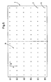
- Figure 2 shows the previous status of Technology with approximately even spacing of the fastening or connecting screw connections 7 in levels E1 to E6 including level E2 of Badador Kunststoffes.
- Figure 2 is correspondingly schematized for ease of understanding Service.
- Figures 3 to 5 show the attachment of mold plates according to the invention a continuous casting mold made of a copper alloy with a variety of schematized Screws 7, the at least in the area (B) of the bath level Melt in the mold 1 at least locally the horizontal distance H of the screw connections 7 is smaller than the vertical distance V of the screw connections, such as this is shown in particular in FIG. 4.
- the horizontal is particularly advantageous Distance H of the screw connections 7 is approximately 50% to 80% of the vertical distance V of the fittings. This will stress the mold plates reduced and crack formation on the hot side of the mold plate prevented.
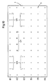
- schematic FIG. 6 shows that by the special type of optimized fastening the stress on the panels reduced and cracks are avoided and thus the mold life and the product quality is improved if the previous arrangement of the Screw bolt (7) in the bathroom mirror area E2 is omitted and additional ones instead Bolts (double rows 4/4) in the first and third levels E1 and E3 can be arranged.
- Figure 9 shows another embodiment of the inventive principle, which is that in levels E1 and E3 instead of an increased number of fittings such fittings 4+ with a larger diameter and accordingly increased strength are arranged.
- Figure 10 shows another alternative of an optimized fastening of mold plates with double rows in some areas Bolts 4/4 in levels E1 and E3 and with reinforced bolts 4+ in the middle of level E2.
Landscapes
- Engineering & Computer Science (AREA)
- Mechanical Engineering (AREA)
- Continuous Casting (AREA)
- Moulding By Coating Moulds (AREA)
- Road Signs Or Road Markings (AREA)
Abstract
Description
- Figur 1
- in perspektivischer Ansicht schräg von oben eine Kokille mit Wasserkästen sowie mit einen Gießhohlraum ausbildenden Kokillenplatten in üblicher Anordnung nach dem Stand der Technik;
- Figur 2
- eine Anordnung von Befestigungsgewinden nach dem Stand der Technik in schematisierter Darstellung;
- Figur 3 bis Figur 5
- optimierte Kokillenplatten-Befestigungen nach der Erfindung mit Verschraubungen, deren horizontaler Abstand kleiner als der vertikale Abstand ist;
- Figur 6
- eine optimierte Kokillenplatten-Befestigung nach der Erfindung mit Wegfall der Verschraubungen im Badspiegelbereich und statt dessen eine zusätzliche Anordnung von schematisierten Schraubenbolzen in der ersten und dritten Befestigungsebene; eine zusätzliche Anordnung von schematisierten Schraubenbolzen in der ersten und dritten Befestigungsebene;
- Figur 7
- eine erfindungsgemäße Ausbildung der optimierten Befestigung von Kokillenplatten mit Wegfall der Verschraubungen im Badspiegelbereich und als Ersatz eine erhöhte Anzahl von Schraubenbolzen in der ersten und dritten Befestigungsebene;
- Figur 8
- eine weitere optimierte Befestigung von Kokillenplatten mit einer Kombination von Schraubenbolzen in Doppelreihe mit erhöhter Anzahl von Schraubenbolzen in verschiedenen Befestigungsebenen;
- Figur 9
- eine optimierte Befestigung anderer Art mit größeren Schraubenbolzen in der ersten und dritten Befestigungsebene als Ersatz für im Badspiegelbereich wegfallender Verschraubungen;
- Figur 10
- eine weitere Art der Befestigung von Kokillenplatten, bereichsweise einerseits mit Doppelreihen und andererseits mit Schraubenbolzen größerer Dimension;
Claims (9)
- Befestigung von Kokillenplatten (5, 6) einer Stranggießkokille (1), bestehend aus wärmeleitendem Metall, insbesondere aus einer Kupferlegierung, ggf. mit Stützplatten an den Außenflächen, die zwischen sich Kühlwasserkanäle begrenzen und miteinander bzw. auf Wasserkästen (8, 9) mit einer Vielzahl von Verschraubungen (7) wie Schraubenbolzen (7) oder dergleichen zusammenspannbar bzw. befestigbar sind,
dadurch gekennzeichnet, dass wenigstens im Bereich (B) des Badspiegels der Kokille (1) zumindest örtlich der horizontale Abstand (H) der Verschraubungen (7) kleiner ist als der vertikale Abstand (V) der Verschraubungen (7). (Fig. 3 bis 5) - Befestigung von Kokillenplatten nach Anspruch 1,
dadurch gekennzeichnet, dass der horizontale Abstand (H) der Verschraubungen (7) etwa 50 bis 80 % des vertikalen Abstands (V) beträgt. (Fig. 5) - Befestigung von Kokillenplatten (5, 6) einer Stranggießkokille (1) bestehend aus wärmeleitendem Metall, insbesondere aus einer Kupferlegierung, ggfs. mit Stützplatten an den Außenflächen, die zwischen sich Kühlwasserkanäle begrenzen und miteinander bzw. auf Wasserkästen (8, 9) mit einer Vielzahl von Verschraubungen (7) wie Schraubenbolzen (7) oder dergleichen zusammenspannbar bzw. befestigbar sind,
dadurch gekennzeihnet,
dass in der Ebene (E2) des Badspiegels der Kokille (1) bei der Befestigung der Kokillenplatten (5, 6) zumindest abschnittsweise Verschraubungen (7) weggelassen und zur Kompensation der damit fehlenden Verspannungskräfte ober- und/oder unterhalb der Ebene (E2) des Badspiegels zusätzliche Gewindeanordnungen (4 / 4) bzw. Verschraubungen vorgesehen sind (Figur 6). - Befestigung von Kokillenplatten einer Stranggießkokille (1) bestehend aus wärmeleitendem Metall, insbesondere aus einer Kupferlegierung, ggfs. mit Stützplatten an den Außenflächen, die zwischen sich Kühlwasserkanäle begrenzen und miteinander bzw. auf Wasserkästen durch eine Vielzahl von Verschraubungen (7) wie Schraubenbolzen oder dergleichen zusammenspannbar bzw. befestigbar sind,
dadurch gekennzeichnet, dass in der Ebene (E2) des Badspiegels der Kokille (1) bei der Befestigung der Kokillenplatten (5, 6) zumindest abschnittsweise Verschraubungen (7) weggelassen und ersatzweise in den Ebenen (E1, E3) oberhalb und unterhalb der Ebene (E2) des Badspiegels relativ größere Gewinde (4+) für entsprechend dickere Schraubenbolzen (7+) vorgesehen sind (Figur 9). - Befestigung von Kokillenplatten nach Anspruch 3,
dadurch gekennzeichnet, dass zur Kompensation von in der Ebene (E2) des Badspiegels entfallenen Verschraubungen (7) eine entsprechende Anzahl von Schraubenbolzen in Doppelreihe (4 / 4) in der ersten und/oder dritten Ebene (E1, E3) angeordnet ist (Figur 8). - Befestigung nach Anspruch 3,
dadurch gekennzeichnet, dass zur Kompensation von in der Ebene (E2) des Badspiegels entfallenen Verschraubungen (7) eine entsprechende Anzahl zusätzlicher Schraubenbolzen in dichterer Reihe der ersten und/oder dritten Ebene (E1, E3) zugeordnet sind (Figur 7). - Befestigung nach einem der Ansprüche 3 oder 5,
dadurch gekennzeichnet, dass zur Kompensation von in der Ebene (E2) des Badspiegels entfallener Verschraubungen (7) eine entsprechende Anzahl zusätzlicher Schraubenbolzen (4, 4) in dichterer Reihe der Ebene (E1) und eine vertikale Verdoppelung der Reihe (4 / 4) der dritten Ebene (E3) vorgesehen ist. - Befestigung nach einem oder mehreren der Ansprüche 3 bis 7,
dadurch gekennzeichnet, dass zur Kompensation von in der Ebene (E2) des Badspiegels entfallener Verschraubungen (7) bereichsweise abwechselnd in den Ebenen (E1, E3) eine entsprechende Anzahl von Schraubenbolzen (4) in Doppelreihe und/oder in vertikaler Verdopplung angeordnet ist. - Befestigung nach einem oder mehreren der Ansprüche 3 bis 8,
dadurch gekennzeichnet, dass zur bereichsweisen Kompensation von in der Ebene (E2) des Badspiegels entfallener Verschraubungen (7) eine bereichsweise horizontale oder vertikale Verdoppelung von Schraubenbolzen (4 / 4) in den Ebenen (E1, E3) vorgenommen wird und in der Ebene E2 abschnittsweise relativ größere Gewinde für entsprechend dickere Schraubenbolzen (4+) vorgesehen sind (Fig. 10).
Applications Claiming Priority (2)
| Application Number | Priority Date | Filing Date | Title |
|---|---|---|---|
| DE10308434 | 2003-02-27 | ||
| DE10308434A DE10308434A1 (de) | 2003-02-27 | 2003-02-27 | Optimierte Befestigung von Kokillenplatten |
Publications (2)
| Publication Number | Publication Date |
|---|---|
| EP1452253A1 true EP1452253A1 (de) | 2004-09-01 |
| EP1452253B1 EP1452253B1 (de) | 2005-10-05 |
Family
ID=32748072
Family Applications (1)
| Application Number | Title | Priority Date | Filing Date |
|---|---|---|---|
| EP04002520A Expired - Lifetime EP1452253B1 (de) | 2003-02-27 | 2004-02-05 | Optimierte Befestigung von Kokillenplatten |
Country Status (3)
| Country | Link |
|---|---|
| EP (1) | EP1452253B1 (de) |
| AT (1) | ATE305832T1 (de) |
| DE (2) | DE10308434A1 (de) |
Citations (4)
| Publication number | Priority date | Publication date | Assignee | Title |
|---|---|---|---|---|
| GB962259A (en) * | 1961-05-16 | 1964-07-01 | Continuous Casting Company Ltd | Improvements relating to moulds for the continuous casting of high melting point metals |
| FR2459093A1 (fr) * | 1979-06-18 | 1981-01-09 | Clesid Sa | Perfectionnement aux lingotieres de coulee continue |
| JPH02104446A (ja) * | 1988-10-11 | 1990-04-17 | Kawasaki Steel Corp | 連続鋳造鋳型の冷却方法及びその実施のための鋳型及び冷却装置 |
| JPH04251638A (ja) * | 1991-01-28 | 1992-09-08 | Kawasaki Steel Corp | 連続鋳造用鋳型 |
-
2003
- 2003-02-27 DE DE10308434A patent/DE10308434A1/de not_active Withdrawn
-
2004
- 2004-02-05 AT AT04002520T patent/ATE305832T1/de active
- 2004-02-05 EP EP04002520A patent/EP1452253B1/de not_active Expired - Lifetime
- 2004-02-05 DE DE502004000077T patent/DE502004000077D1/de not_active Expired - Lifetime
Patent Citations (4)
| Publication number | Priority date | Publication date | Assignee | Title |
|---|---|---|---|---|
| GB962259A (en) * | 1961-05-16 | 1964-07-01 | Continuous Casting Company Ltd | Improvements relating to moulds for the continuous casting of high melting point metals |
| FR2459093A1 (fr) * | 1979-06-18 | 1981-01-09 | Clesid Sa | Perfectionnement aux lingotieres de coulee continue |
| JPH02104446A (ja) * | 1988-10-11 | 1990-04-17 | Kawasaki Steel Corp | 連続鋳造鋳型の冷却方法及びその実施のための鋳型及び冷却装置 |
| JPH04251638A (ja) * | 1991-01-28 | 1992-09-08 | Kawasaki Steel Corp | 連続鋳造用鋳型 |
Non-Patent Citations (2)
| Title |
|---|
| PATENT ABSTRACTS OF JAPAN vol. 014, no. 315 (M - 0995) 6 July 1990 (1990-07-06) * |
| PATENT ABSTRACTS OF JAPAN vol. 017, no. 027 (M - 1355) 19 January 1993 (1993-01-19) * |
Also Published As
| Publication number | Publication date |
|---|---|
| DE10308434A1 (de) | 2004-09-09 |
| DE502004000077D1 (de) | 2006-02-16 |
| ATE305832T1 (de) | 2005-10-15 |
| EP1452253B1 (de) | 2005-10-05 |
Similar Documents
| Publication | Publication Date | Title |
|---|---|---|
| EP0912271B1 (de) | Flüssigkeitsgekühlte kokille | |
| EP1398099B1 (de) | Flüssigkeitsgekühlte Kokille zum Stranggiessen von Metallen | |
| CH623759A5 (de) | ||
| EP0730923A1 (de) | Kokille zum Stranggiessen von Metallen | |
| DE102016124801B3 (de) | Kokillenplatte und Kokille | |
| DE102009056919B4 (de) | Zylinderlaufbuchse | |
| EP1704005B1 (de) | Giessmaschine | |
| EP1555073B1 (de) | Flüssigkeitsgekühlte Stranggiesskokille | |
| DE102023112607B3 (de) | Kokille | |
| EP2483017B1 (de) | Giessform | |
| EP1736257B1 (de) | Flüssigkeitsgekühlte Kokille zum Stranggiessen von Metallen | |
| EP1452253B1 (de) | Optimierte Befestigung von Kokillenplatten | |
| EP2083957B1 (de) | Stranggiesskokille | |
| EP1007246B1 (de) | Stranggiesskokille | |
| AT522298B1 (de) | Kokilleneinheit zum Stranggießen von Metallprodukten sowie Stranggießanlage | |
| EP0965401A1 (de) | Kokillenwand einer Stranggiesskokille | |
| DE102007001931A1 (de) | Kokillenwand | |
| EP1025930A1 (de) | Kokillenplatte einer Kokille mit trichterförmigem Eingiessbereich zum Stranggiessen von Metall | |
| EP3870898B1 (de) | Roststab für stufenrost | |
| DE19801728C1 (de) | Stranggießkokille | |
| DE2446505C2 (de) | Blockkokille zum Herstellen metallischer Blöcke, Knüppel oder Brammen | |
| DE2615228A1 (de) | Stranggussform | |
| EP3917700B1 (de) | Kokillenplatte | |
| EP3898028B1 (de) | Kokilleneinheit zum stranggiessen von metallprodukten sowie stranggiessanlage | |
| DE2020846A1 (de) | Kolben fuer eine Brennkraftmaschine |
Legal Events
| Date | Code | Title | Description |
|---|---|---|---|
| PUAI | Public reference made under article 153(3) epc to a published international application that has entered the european phase |
Free format text: ORIGINAL CODE: 0009012 |
|
| 17P | Request for examination filed |
Effective date: 20040205 |
|
| AK | Designated contracting states |
Kind code of ref document: A1 Designated state(s): AT BE BG CH CY CZ DE DK EE ES FI FR GB GR HU IE IT LI LU MC NL PT RO SE SI SK TR |
|
| AX | Request for extension of the european patent |
Extension state: AL LT LV MK |
|
| GRAP | Despatch of communication of intention to grant a patent |
Free format text: ORIGINAL CODE: EPIDOSNIGR1 |
|
| AKX | Designation fees paid |
Designated state(s): AT BE BG CH CY CZ DE DK EE ES FI FR GB GR HU IE IT LI LU MC NL PT RO SE SI SK TR |
|
| TCAT | At: translation of patent claims filed | ||
| GRAS | Grant fee paid |
Free format text: ORIGINAL CODE: EPIDOSNIGR3 |
|
| GRAA | (expected) grant |
Free format text: ORIGINAL CODE: 0009210 |
|
| AK | Designated contracting states |
Kind code of ref document: B1 Designated state(s): AT BE BG CH CY CZ DE DK EE ES FI FR GB GR HU IE IT LI LU MC NL PT RO SE SI SK TR |
|
| PG25 | Lapsed in a contracting state [announced via postgrant information from national office to epo] |
Ref country code: IE Free format text: LAPSE BECAUSE OF FAILURE TO SUBMIT A TRANSLATION OF THE DESCRIPTION OR TO PAY THE FEE WITHIN THE PRESCRIBED TIME-LIMIT Effective date: 20051005 Ref country code: SK Free format text: LAPSE BECAUSE OF FAILURE TO SUBMIT A TRANSLATION OF THE DESCRIPTION OR TO PAY THE FEE WITHIN THE PRESCRIBED TIME-LIMIT Effective date: 20051005 Ref country code: CZ Free format text: LAPSE BECAUSE OF FAILURE TO SUBMIT A TRANSLATION OF THE DESCRIPTION OR TO PAY THE FEE WITHIN THE PRESCRIBED TIME-LIMIT Effective date: 20051005 Ref country code: FI Free format text: LAPSE BECAUSE OF FAILURE TO SUBMIT A TRANSLATION OF THE DESCRIPTION OR TO PAY THE FEE WITHIN THE PRESCRIBED TIME-LIMIT Effective date: 20051005 Ref country code: RO Free format text: LAPSE BECAUSE OF FAILURE TO SUBMIT A TRANSLATION OF THE DESCRIPTION OR TO PAY THE FEE WITHIN THE PRESCRIBED TIME-LIMIT Effective date: 20051005 Ref country code: SI Free format text: LAPSE BECAUSE OF FAILURE TO SUBMIT A TRANSLATION OF THE DESCRIPTION OR TO PAY THE FEE WITHIN THE PRESCRIBED TIME-LIMIT Effective date: 20051005 Ref country code: NL Free format text: LAPSE BECAUSE OF FAILURE TO SUBMIT A TRANSLATION OF THE DESCRIPTION OR TO PAY THE FEE WITHIN THE PRESCRIBED TIME-LIMIT Effective date: 20051005 |
|
| REG | Reference to a national code |
Ref country code: GB Ref legal event code: FG4D Free format text: NOT ENGLISH |
|
| REG | Reference to a national code |
Ref country code: CH Ref legal event code: EP |
|
| REG | Reference to a national code |
Ref country code: IE Ref legal event code: FG4D Free format text: LANGUAGE OF EP DOCUMENT: GERMAN |
|
| PG25 | Lapsed in a contracting state [announced via postgrant information from national office to epo] |
Ref country code: SE Free format text: LAPSE BECAUSE OF FAILURE TO SUBMIT A TRANSLATION OF THE DESCRIPTION OR TO PAY THE FEE WITHIN THE PRESCRIBED TIME-LIMIT Effective date: 20060105 Ref country code: BG Free format text: LAPSE BECAUSE OF FAILURE TO SUBMIT A TRANSLATION OF THE DESCRIPTION OR TO PAY THE FEE WITHIN THE PRESCRIBED TIME-LIMIT Effective date: 20060105 Ref country code: DK Free format text: LAPSE BECAUSE OF FAILURE TO SUBMIT A TRANSLATION OF THE DESCRIPTION OR TO PAY THE FEE WITHIN THE PRESCRIBED TIME-LIMIT Effective date: 20060105 Ref country code: GR Free format text: LAPSE BECAUSE OF FAILURE TO SUBMIT A TRANSLATION OF THE DESCRIPTION OR TO PAY THE FEE WITHIN THE PRESCRIBED TIME-LIMIT Effective date: 20060105 |
|
| PG25 | Lapsed in a contracting state [announced via postgrant information from national office to epo] |
Ref country code: ES Free format text: LAPSE BECAUSE OF FAILURE TO SUBMIT A TRANSLATION OF THE DESCRIPTION OR TO PAY THE FEE WITHIN THE PRESCRIBED TIME-LIMIT Effective date: 20060116 |
|
| GBT | Gb: translation of ep patent filed (gb section 77(6)(a)/1977) |
Effective date: 20060119 |
|
| REF | Corresponds to: |
Ref document number: 502004000077 Country of ref document: DE Date of ref document: 20060216 Kind code of ref document: P |
|
| PG25 | Lapsed in a contracting state [announced via postgrant information from national office to epo] |
Ref country code: LU Free format text: LAPSE BECAUSE OF NON-PAYMENT OF DUE FEES Effective date: 20060228 Ref country code: MC Free format text: LAPSE BECAUSE OF NON-PAYMENT OF DUE FEES Effective date: 20060228 Ref country code: BE Free format text: LAPSE BECAUSE OF NON-PAYMENT OF DUE FEES Effective date: 20060228 |
|
| NLV1 | Nl: lapsed or annulled due to failure to fulfill the requirements of art. 29p and 29m of the patents act | ||
| PG25 | Lapsed in a contracting state [announced via postgrant information from national office to epo] |
Ref country code: PT Free format text: LAPSE BECAUSE OF FAILURE TO SUBMIT A TRANSLATION OF THE DESCRIPTION OR TO PAY THE FEE WITHIN THE PRESCRIBED TIME-LIMIT Effective date: 20060306 |
|
| PG25 | Lapsed in a contracting state [announced via postgrant information from national office to epo] |
Ref country code: HU Free format text: LAPSE BECAUSE OF FAILURE TO SUBMIT A TRANSLATION OF THE DESCRIPTION OR TO PAY THE FEE WITHIN THE PRESCRIBED TIME-LIMIT Effective date: 20060406 |
|
| REG | Reference to a national code |
Ref country code: IE Ref legal event code: FD4D |
|
| PLBE | No opposition filed within time limit |
Free format text: ORIGINAL CODE: 0009261 |
|
| STAA | Information on the status of an ep patent application or granted ep patent |
Free format text: STATUS: NO OPPOSITION FILED WITHIN TIME LIMIT |
|
| 26N | No opposition filed |
Effective date: 20060706 |
|
| PG25 | Lapsed in a contracting state [announced via postgrant information from national office to epo] |
Ref country code: FR Free format text: LAPSE BECAUSE OF FAILURE TO SUBMIT A TRANSLATION OF THE DESCRIPTION OR TO PAY THE FEE WITHIN THE PRESCRIBED TIME-LIMIT Effective date: 20061020 |
|
| EN | Fr: translation not filed | ||
| BERE | Be: lapsed |
Owner name: SMS DEMAG A.G. Effective date: 20060228 |
|
| PG25 | Lapsed in a contracting state [announced via postgrant information from national office to epo] |
Ref country code: EE Free format text: LAPSE BECAUSE OF FAILURE TO SUBMIT A TRANSLATION OF THE DESCRIPTION OR TO PAY THE FEE WITHIN THE PRESCRIBED TIME-LIMIT Effective date: 20051005 |
|
| PG25 | Lapsed in a contracting state [announced via postgrant information from national office to epo] |
Ref country code: TR Free format text: LAPSE BECAUSE OF FAILURE TO SUBMIT A TRANSLATION OF THE DESCRIPTION OR TO PAY THE FEE WITHIN THE PRESCRIBED TIME-LIMIT Effective date: 20051005 |
|
| REG | Reference to a national code |
Ref country code: CH Ref legal event code: PL |
|
| PG25 | Lapsed in a contracting state [announced via postgrant information from national office to epo] |
Ref country code: CH Free format text: LAPSE BECAUSE OF NON-PAYMENT OF DUE FEES Effective date: 20080229 Ref country code: LI Free format text: LAPSE BECAUSE OF NON-PAYMENT OF DUE FEES Effective date: 20080229 |
|
| PG25 | Lapsed in a contracting state [announced via postgrant information from national office to epo] |
Ref country code: CY Free format text: LAPSE BECAUSE OF FAILURE TO SUBMIT A TRANSLATION OF THE DESCRIPTION OR TO PAY THE FEE WITHIN THE PRESCRIBED TIME-LIMIT Effective date: 20051005 Ref country code: FR Free format text: LAPSE BECAUSE OF FAILURE TO SUBMIT A TRANSLATION OF THE DESCRIPTION OR TO PAY THE FEE WITHIN THE PRESCRIBED TIME-LIMIT Effective date: 20051005 |
|
| PGFP | Annual fee paid to national office [announced via postgrant information from national office to epo] |
Ref country code: IT Payment date: 20110219 Year of fee payment: 8 Ref country code: AT Payment date: 20110214 Year of fee payment: 8 Ref country code: DE Payment date: 20110218 Year of fee payment: 8 |
|
| PGFP | Annual fee paid to national office [announced via postgrant information from national office to epo] |
Ref country code: GB Payment date: 20110217 Year of fee payment: 8 |
|
| GBPC | Gb: european patent ceased through non-payment of renewal fee |
Effective date: 20120205 |
|
| PG25 | Lapsed in a contracting state [announced via postgrant information from national office to epo] |
Ref country code: IT Free format text: LAPSE BECAUSE OF NON-PAYMENT OF DUE FEES Effective date: 20120205 |
|
| REG | Reference to a national code |
Ref country code: AT Ref legal event code: MM01 Ref document number: 305832 Country of ref document: AT Kind code of ref document: T Effective date: 20120205 |
|
| REG | Reference to a national code |
Ref country code: DE Ref legal event code: R119 Ref document number: 502004000077 Country of ref document: DE Effective date: 20120901 |
|
| PG25 | Lapsed in a contracting state [announced via postgrant information from national office to epo] |
Ref country code: AT Free format text: LAPSE BECAUSE OF NON-PAYMENT OF DUE FEES Effective date: 20120205 Ref country code: GB Free format text: LAPSE BECAUSE OF NON-PAYMENT OF DUE FEES Effective date: 20120205 |
|
| PG25 | Lapsed in a contracting state [announced via postgrant information from national office to epo] |
Ref country code: DE Free format text: LAPSE BECAUSE OF NON-PAYMENT OF DUE FEES Effective date: 20120901 |