EP1450981B1 - Contact tip for electric arc welding using consumable wire - Google Patents
Contact tip for electric arc welding using consumable wire Download PDFInfo
- Publication number
- EP1450981B1 EP1450981B1 EP02771907A EP02771907A EP1450981B1 EP 1450981 B1 EP1450981 B1 EP 1450981B1 EP 02771907 A EP02771907 A EP 02771907A EP 02771907 A EP02771907 A EP 02771907A EP 1450981 B1 EP1450981 B1 EP 1450981B1
- Authority
- EP
- European Patent Office
- Prior art keywords
- tip
- wire
- bore
- contact
- length
- Prior art date
- Legal status (The legal status is an assumption and is not a legal conclusion. Google has not performed a legal analysis and makes no representation as to the accuracy of the status listed.)
- Expired - Lifetime
Links
- 238000003466 welding Methods 0.000 title claims abstract description 141
- 238000010891 electric arc Methods 0.000 title claims abstract description 17
- OKTJSMMVPCPJKN-UHFFFAOYSA-N Carbon Chemical compound [C] OKTJSMMVPCPJKN-UHFFFAOYSA-N 0.000 claims description 80
- 229910002804 graphite Inorganic materials 0.000 claims description 79
- 239000010439 graphite Substances 0.000 claims description 79
- 239000000463 material Substances 0.000 claims description 55
- 230000002829 reductive effect Effects 0.000 claims description 40
- 229910000881 Cu alloy Inorganic materials 0.000 claims description 30
- 229910000831 Steel Inorganic materials 0.000 claims description 21
- 239000010959 steel Substances 0.000 claims description 21
- WFKWXMTUELFFGS-UHFFFAOYSA-N tungsten Chemical compound [W] WFKWXMTUELFFGS-UHFFFAOYSA-N 0.000 claims description 16
- 229910052721 tungsten Inorganic materials 0.000 claims description 16
- 239000010937 tungsten Substances 0.000 claims description 16
- 230000008859 change Effects 0.000 claims description 11
- RYGMFSIKBFXOCR-UHFFFAOYSA-N Copper Chemical compound [Cu] RYGMFSIKBFXOCR-UHFFFAOYSA-N 0.000 description 102
- 239000010949 copper Substances 0.000 description 100
- 229910052802 copper Inorganic materials 0.000 description 99
- 230000008018 melting Effects 0.000 description 52
- 238000002844 melting Methods 0.000 description 52
- 239000000919 ceramic Substances 0.000 description 48
- 229910052751 metal Inorganic materials 0.000 description 42
- 239000002184 metal Substances 0.000 description 42
- 238000012546 transfer Methods 0.000 description 39
- 238000010438 heat treatment Methods 0.000 description 28
- 239000011324 bead Substances 0.000 description 24
- 230000009467 reduction Effects 0.000 description 20
- 238000000151 deposition Methods 0.000 description 19
- 230000008021 deposition Effects 0.000 description 19
- 230000000694 effects Effects 0.000 description 16
- 238000000034 method Methods 0.000 description 15
- 238000013461 design Methods 0.000 description 14
- 230000008569 process Effects 0.000 description 13
- 230000008901 benefit Effects 0.000 description 12
- 239000002131 composite material Substances 0.000 description 11
- 229910001209 Low-carbon steel Inorganic materials 0.000 description 10
- 239000007789 gas Substances 0.000 description 10
- 230000007246 mechanism Effects 0.000 description 10
- 239000007921 spray Substances 0.000 description 10
- PXHVJJICTQNCMI-UHFFFAOYSA-N Nickel Chemical compound [Ni] PXHVJJICTQNCMI-UHFFFAOYSA-N 0.000 description 9
- 229910000971 Silver steel Inorganic materials 0.000 description 9
- 239000000758 substrate Substances 0.000 description 9
- 238000012360 testing method Methods 0.000 description 9
- 239000004411 aluminium Substances 0.000 description 7
- 229910052782 aluminium Inorganic materials 0.000 description 7
- XAGFODPZIPBFFR-UHFFFAOYSA-N aluminium Chemical compound [Al] XAGFODPZIPBFFR-UHFFFAOYSA-N 0.000 description 7
- 239000003517 fume Substances 0.000 description 7
- 229910001060 Gray iron Inorganic materials 0.000 description 6
- 230000007423 decrease Effects 0.000 description 6
- 230000004927 fusion Effects 0.000 description 6
- 229910001338 liquidmetal Inorganic materials 0.000 description 6
- CURLTUGMZLYLDI-UHFFFAOYSA-N Carbon dioxide Chemical compound O=C=O CURLTUGMZLYLDI-UHFFFAOYSA-N 0.000 description 5
- CWYNVVGOOAEACU-UHFFFAOYSA-N Fe2+ Chemical compound [Fe+2] CWYNVVGOOAEACU-UHFFFAOYSA-N 0.000 description 5
- 229910045601 alloy Inorganic materials 0.000 description 5
- 239000000956 alloy Substances 0.000 description 5
- 239000011651 chromium Substances 0.000 description 5
- 239000004020 conductor Substances 0.000 description 5
- 238000003754 machining Methods 0.000 description 5
- 230000004048 modification Effects 0.000 description 5
- 238000012986 modification Methods 0.000 description 5
- XKRFYHLGVUSROY-UHFFFAOYSA-N Argon Chemical compound [Ar] XKRFYHLGVUSROY-UHFFFAOYSA-N 0.000 description 4
- VYZAMTAEIAYCRO-UHFFFAOYSA-N Chromium Chemical compound [Cr] VYZAMTAEIAYCRO-UHFFFAOYSA-N 0.000 description 4
- 229910001037 White iron Inorganic materials 0.000 description 4
- 230000002411 adverse Effects 0.000 description 4
- 238000004458 analytical method Methods 0.000 description 4
- 229910052804 chromium Inorganic materials 0.000 description 4
- 238000000576 coating method Methods 0.000 description 4
- 238000010276 construction Methods 0.000 description 4
- 230000005672 electromagnetic field Effects 0.000 description 4
- 230000003628 erosive effect Effects 0.000 description 4
- 239000000203 mixture Substances 0.000 description 4
- 229910052759 nickel Inorganic materials 0.000 description 4
- XLYOFNOQVPJJNP-UHFFFAOYSA-N water Substances O XLYOFNOQVPJJNP-UHFFFAOYSA-N 0.000 description 4
- 239000004809 Teflon Substances 0.000 description 3
- 229920006362 Teflon® Polymers 0.000 description 3
- PNEYBMLMFCGWSK-UHFFFAOYSA-N aluminium oxide Inorganic materials [O-2].[O-2].[O-2].[Al+3].[Al+3] PNEYBMLMFCGWSK-UHFFFAOYSA-N 0.000 description 3
- 229910052799 carbon Inorganic materials 0.000 description 3
- 229910002092 carbon dioxide Inorganic materials 0.000 description 3
- 239000004568 cement Substances 0.000 description 3
- 229910010293 ceramic material Inorganic materials 0.000 description 3
- 239000011248 coating agent Substances 0.000 description 3
- 230000007547 defect Effects 0.000 description 3
- 210000003298 dental enamel Anatomy 0.000 description 3
- 239000012777 electrically insulating material Substances 0.000 description 3
- 230000004907 flux Effects 0.000 description 3
- 238000005552 hardfacing Methods 0.000 description 3
- 239000004922 lacquer Substances 0.000 description 3
- 238000004519 manufacturing process Methods 0.000 description 3
- 230000002035 prolonged effect Effects 0.000 description 3
- 239000011819 refractory material Substances 0.000 description 3
- 230000000717 retained effect Effects 0.000 description 3
- HBMJWWWQQXIZIP-UHFFFAOYSA-N silicon carbide Chemical compound [Si+]#[C-] HBMJWWWQQXIZIP-UHFFFAOYSA-N 0.000 description 3
- 229910010271 silicon carbide Inorganic materials 0.000 description 3
- 230000001052 transient effect Effects 0.000 description 3
- 229910000838 Al alloy Inorganic materials 0.000 description 2
- XEEYBQQBJWHFJM-UHFFFAOYSA-N Iron Chemical compound [Fe] XEEYBQQBJWHFJM-UHFFFAOYSA-N 0.000 description 2
- XUIMIQQOPSSXEZ-UHFFFAOYSA-N Silicon Chemical compound [Si] XUIMIQQOPSSXEZ-UHFFFAOYSA-N 0.000 description 2
- 229910001315 Tool steel Inorganic materials 0.000 description 2
- 239000000853 adhesive Substances 0.000 description 2
- 230000001070 adhesive effect Effects 0.000 description 2
- 238000013459 approach Methods 0.000 description 2
- 229910052786 argon Inorganic materials 0.000 description 2
- 229910052790 beryllium Inorganic materials 0.000 description 2
- 239000001569 carbon dioxide Substances 0.000 description 2
- 238000001816 cooling Methods 0.000 description 2
- 230000006866 deterioration Effects 0.000 description 2
- 238000010790 dilution Methods 0.000 description 2
- 239000012895 dilution Substances 0.000 description 2
- 238000005516 engineering process Methods 0.000 description 2
- 230000005496 eutectics Effects 0.000 description 2
- 238000001704 evaporation Methods 0.000 description 2
- 230000008020 evaporation Effects 0.000 description 2
- 238000002474 experimental method Methods 0.000 description 2
- 239000010408 film Substances 0.000 description 2
- 239000004519 grease Substances 0.000 description 2
- 230000006872 improvement Effects 0.000 description 2
- 239000011261 inert gas Substances 0.000 description 2
- 239000011572 manganese Substances 0.000 description 2
- 230000013011 mating Effects 0.000 description 2
- 239000000155 melt Substances 0.000 description 2
- 150000002739 metals Chemical class 0.000 description 2
- 239000002245 particle Substances 0.000 description 2
- 230000035515 penetration Effects 0.000 description 2
- 229910052710 silicon Inorganic materials 0.000 description 2
- 239000010703 silicon Substances 0.000 description 2
- 239000007787 solid Substances 0.000 description 2
- 239000000126 substance Substances 0.000 description 2
- 229910000859 α-Fe Inorganic materials 0.000 description 2
- 229910000952 Be alloy Inorganic materials 0.000 description 1
- 229910000975 Carbon steel Inorganic materials 0.000 description 1
- 229910001018 Cast iron Inorganic materials 0.000 description 1
- 229910017526 Cu-Cr-Zr Inorganic materials 0.000 description 1
- 229910017810 Cu—Cr—Zr Inorganic materials 0.000 description 1
- PWHULOQIROXLJO-UHFFFAOYSA-N Manganese Chemical compound [Mn] PWHULOQIROXLJO-UHFFFAOYSA-N 0.000 description 1
- 241000656145 Thyrsites atun Species 0.000 description 1
- QCWXUUIWCKQGHC-UHFFFAOYSA-N Zirconium Chemical compound [Zr] QCWXUUIWCKQGHC-UHFFFAOYSA-N 0.000 description 1
- 238000007792 addition Methods 0.000 description 1
- 230000001464 adherent effect Effects 0.000 description 1
- 230000004075 alteration Effects 0.000 description 1
- 230000003466 anti-cipated effect Effects 0.000 description 1
- QVGXLLKOCUKJST-UHFFFAOYSA-N atomic oxygen Chemical compound [O] QVGXLLKOCUKJST-UHFFFAOYSA-N 0.000 description 1
- 229910001566 austenite Inorganic materials 0.000 description 1
- 230000009286 beneficial effect Effects 0.000 description 1
- DMFGNRRURHSENX-UHFFFAOYSA-N beryllium copper Chemical compound [Be].[Cu] DMFGNRRURHSENX-UHFFFAOYSA-N 0.000 description 1
- 230000015572 biosynthetic process Effects 0.000 description 1
- 238000009835 boiling Methods 0.000 description 1
- 239000010941 cobalt Substances 0.000 description 1
- 229910017052 cobalt Inorganic materials 0.000 description 1
- GUTLYIVDDKVIGB-UHFFFAOYSA-N cobalt atom Chemical compound [Co] GUTLYIVDDKVIGB-UHFFFAOYSA-N 0.000 description 1
- 230000001010 compromised effect Effects 0.000 description 1
- SBYXRAKIOMOBFF-UHFFFAOYSA-N copper tungsten Chemical compound [Cu].[W] SBYXRAKIOMOBFF-UHFFFAOYSA-N 0.000 description 1
- 210000001787 dendrite Anatomy 0.000 description 1
- 230000001419 dependent effect Effects 0.000 description 1
- 238000005137 deposition process Methods 0.000 description 1
- 230000001627 detrimental effect Effects 0.000 description 1
- 238000009826 distribution Methods 0.000 description 1
- 238000005553 drilling Methods 0.000 description 1
- 238000001035 drying Methods 0.000 description 1
- 239000002320 enamel (paints) Substances 0.000 description 1
- 230000003090 exacerbative effect Effects 0.000 description 1
- -1 ferrous metals Chemical class 0.000 description 1
- 239000007770 graphite material Substances 0.000 description 1
- 238000009863 impact test Methods 0.000 description 1
- 238000007689 inspection Methods 0.000 description 1
- 239000011810 insulating material Substances 0.000 description 1
- 230000003993 interaction Effects 0.000 description 1
- 229910052742 iron Inorganic materials 0.000 description 1
- 235000000396 iron Nutrition 0.000 description 1
- 238000009533 lab test Methods 0.000 description 1
- 238000002789 length control Methods 0.000 description 1
- 230000000670 limiting effect Effects 0.000 description 1
- 238000012423 maintenance Methods 0.000 description 1
- 229910052748 manganese Inorganic materials 0.000 description 1
- 239000011159 matrix material Substances 0.000 description 1
- 239000007769 metal material Substances 0.000 description 1
- 238000001465 metallisation Methods 0.000 description 1
- 238000001000 micrograph Methods 0.000 description 1
- 239000001301 oxygen Substances 0.000 description 1
- 229910052760 oxygen Inorganic materials 0.000 description 1
- 239000000843 powder Substances 0.000 description 1
- 238000003825 pressing Methods 0.000 description 1
- 230000001681 protective effect Effects 0.000 description 1
- 230000005855 radiation Effects 0.000 description 1
- 239000002994 raw material Substances 0.000 description 1
- 230000004044 response Effects 0.000 description 1
- 229910000679 solder Inorganic materials 0.000 description 1
- 229910001220 stainless steel Inorganic materials 0.000 description 1
- 239000010935 stainless steel Substances 0.000 description 1
- 238000009864 tensile test Methods 0.000 description 1
- 239000002470 thermal conductor Substances 0.000 description 1
- 239000010409 thin film Substances 0.000 description 1
- 230000009466 transformation Effects 0.000 description 1
- 230000007704 transition Effects 0.000 description 1
- 239000003496 welding fume Substances 0.000 description 1
- 238000004804 winding Methods 0.000 description 1
- 229910052726 zirconium Inorganic materials 0.000 description 1
Images


Classifications
-
- B—PERFORMING OPERATIONS; TRANSPORTING
- B23—MACHINE TOOLS; METAL-WORKING NOT OTHERWISE PROVIDED FOR
- B23K—SOLDERING OR UNSOLDERING; WELDING; CLADDING OR PLATING BY SOLDERING OR WELDING; CUTTING BY APPLYING HEAT LOCALLY, e.g. FLAME CUTTING; WORKING BY LASER BEAM
- B23K9/00—Arc welding or cutting
- B23K9/24—Features related to electrodes
- B23K9/26—Accessories for electrodes, e.g. ignition tips
-
- B—PERFORMING OPERATIONS; TRANSPORTING
- B23—MACHINE TOOLS; METAL-WORKING NOT OTHERWISE PROVIDED FOR
- B23K—SOLDERING OR UNSOLDERING; WELDING; CLADDING OR PLATING BY SOLDERING OR WELDING; CUTTING BY APPLYING HEAT LOCALLY, e.g. FLAME CUTTING; WORKING BY LASER BEAM
- B23K9/00—Arc welding or cutting
- B23K9/12—Automatic feeding or moving of electrodes or work for spot or seam welding or cutting
- B23K9/122—Devices for guiding electrodes, e.g. guide tubes
- B23K9/123—Serving also as contacting devices supplying welding current to an electrode
-
- B—PERFORMING OPERATIONS; TRANSPORTING
- B23—MACHINE TOOLS; METAL-WORKING NOT OTHERWISE PROVIDED FOR
- B23K—SOLDERING OR UNSOLDERING; WELDING; CLADDING OR PLATING BY SOLDERING OR WELDING; CUTTING BY APPLYING HEAT LOCALLY, e.g. FLAME CUTTING; WORKING BY LASER BEAM
- B23K9/00—Arc welding or cutting
- B23K9/24—Features related to electrodes
- B23K9/28—Supporting devices for electrodes
- B23K9/29—Supporting devices adapted for making use of shielding means
Definitions
- This invention relates to improvements in electric arc welding equipment operable with a consumable electrode and, in particular, to a contact tip according to the preamble of claim 1 (see, for example, JP 5/261 551 ).
- GMAW gas metal arc welding
- MIG metal inert gas
- FCAW flux cored arc welding
- the contact tip is a critical element in welding guns for electric arc welding with a consumable electrode. Its main function is to enable electric current from a welding power supply to be continuously transported to a wire or strip comprising the consumable electrode.
- Contact tips are made of metal, almost exclusively of copper or a copper alloy, because of the high electrical and thermal conductivity of these metals. Usually contact tips are of hard drawn copper of high purity, or of an alloy such as Cu-2% Be, Cu-0.5% Be and suitable Cu-Cr-Zr alloys.
- journal articles such as:
- Heat input is proportional to welding voltage and current and inversely proportional to the travel speed of the welding torch relative to a work piece being welded.
- the welding torch may be held stationary and the work piece moved relative to the torch, the work piece may be held stationary and the torch moved relative to the work piece, or each of the torch and work piece may move but with relative movement therebetween.
- Heat input affects weld penetration, cooling time, weld distortion and metallurgical properties in deposited weld metal and/or in adjacent zones of the work piece. In general, it is advantageous to minimise heat input for a given deposition rate.
- the parameters "a” and “b” depend on the wire diameter (in the case of wire of circular cross-section, or equivalent diameter for wire of other cross-sections) and also on the wire composition. These parameters may be derived for each consumable from measured or published data for deposition rate or wire feed speed.
- the parameter "L" in the above-indicated formula represents the length of the wire between the effective contact point of the wire in the contact tip and the top of the welding arc. This length of the wire differs from the normal use of the parameter L, in which that length is taken as the length of wire exposed beyond the outlet end of the contact tip to the top of the welding arc.
- the interpretation of L in normal use i.e. the electrode extension or stick-out, cannot be relied on. It can be appropriate where the wire makes electrical contact with the contact tip at the outlet end of the bore of the contact tip. In such case, the interpretation corresponds to that for the above-indicated formula, at least where there is a single contact point between the wire and the contact tip. However, where there is a single contact point, this can be at any location along the contact tip bore, from the inlet end to the outlet end of the bore. Also, the location can vary between those extremes during a welding operation, and further variation can result from there intermittently being at least two contact points along the length of the bore.
- the length of the bore is usually greater than the electrode extension or stick-out and, as a consequence, there can be variability of in excess of 100% in the actual length of the wire subjected to resistive heating; both between successive welding operations and during a given welding operation. That is, there can be variability in excess of 100% in the value of L for the purpose of the above-indicated formula as compared with a measure of L to determine electrode extension or stick-out.
- wire melting rate applies to GMAW carried out with welding power supplies operating under essentially constant voltage conditions.
- pulsed power supplies are also used for GMAW. Pulses of electric current are applied to heat the wire consumable and to induce droplet detachment.
- the relation between wire melting rate and current is more complex than the relation given in the equation presented previously. Nevertheless there is a strong dependence of wire melting rate on preheat length and it is critical to performance to maintain a continuous current delivery area within the tip.
- the second issue related to the performance of a tip is the feedability of the wire through the tip.
- the reproducibility with time of the processes associated with droplet transfer process requires that a uniform wire feed speed be established and maintained.
- One of the objectives of this invention is to enable reliable welds to be deposited at wire feed speeds substantially in excess of those possible with conventional GMAW.
- the feed force must therefore be as low as practicable so that the mechanical work applied to the tip is reduced.
- Mechanical work results in wear. Wear creates problems in the electrical contact area and ultimately leads to tip failure and defects in the weld.
- JP-A-05 261551 discloses a contact tip having a double pipe structure having an inside ceramic part and an outside copper part.
- the ceramic part extends 5-10mm from the tip end and the diameter of a wire passing hole at the tip end part is larger than the diameter of hole at other part by 0.1-0.4mm.
- JP-A-11 123559 discloses a high speed MIG welding torch in which a welding wire is pressed against an inner surface of a wire feeding hole with a pressurizing ball while the same is rolled to supply electric power to the welding wire.
- US-A-2428849 discloses a welding electrode nozzle in which a bore has a conical taper inlet, a cylindrical section, a chamber and an exit portion.
- JP-A-2001 300732 discloses a torch member for inert gas welding in which the guide hole of a contact tip supplying a welding wire to a workpiece has a diameter larger than that of the welding wire is provided along the axial line of a main body having a mounting means at one end and a part convergent in outside diameter at the other end, and the guide hole is formed into an at least two-stepped hole with a supporting part having a diameter slightly smaller near an opening end on the convergent side, and thereby the welding wire is supported by the supporting part shorter than the guide hole.
- the present invention seeks to provide a contact tip which enables improved control over electrical contact with a consumable electrode wire and which, as a consequence, enables welding under more stable operating conditions for non pulsed and pulsed power supplies.
- the invention addresses fundamental physical issues of wire feedability and continuous current delivery and, as such the invention can enable enhancement of the performance of a wide variety of welding power supplies designed for GMAW.
- the primary contact region of the bore is close to the inlet end of the bore.
- reference to the bore is intended to denote the passage in which electrical contact is intended to be made, as distinct from a tapered guide leading to the inlet end of the passage or bore and intended for guiding the leading end of an electrode into the passage or bore.
- One benefit of having the primary contact region close to the inlet end of the bore is that it facilitates establishment of a suitable preheat length L of electrode.
- the primary electrical contact may be made in a number of different ways.
- the bore is configured such that the consumable wire electrode, in-passing through the bore, beds into the surface defining the primary contact region of the bore.
- the bore can be configured to provide a slight step in the bore, at the end of the primary contact region nearer to the inlet end of the contact tip whereby that region is of a slightly reduced diameter. With a suitable step, it is found that the electrode reliably beds into the surface defining the primary contact region to establish thereby a primary electrical contact.
- the contact is found to be free of arcing and able to be maintained through a welding run.
- the precise location of the primary contact area depends on the dimensions of the step and the stiffness and curvature of the wire.
- the primary electrical contact achieved by configuring the bore by providing a step is surprising given the characteristics of welding with a conventional contact tip.
- the number and location of contacts can vary, with no one contact providing stable over-riding primary electrical contact and resultant freedom from arcing.
- the presence of the bore configuring in the tip of the invention achieves stability and the contact location remains substantially longitudinally constant. Some circumferential sliding contact may occur in start up with the contact tip of the invention, but this quickly is overcome by the electrode bedding into the surface defining the primary contact region.
- curvature and springiness of the electrode wire appear to be principal factors giving rise to the contact between the wire and contact tip.
- the contact tip of the invention may be about half the standard clearance or tolerance for a given electrode wire in a conventional contact tip.
- the step may reduce the bore diameter from a standard clearance to less than a standard clearance along the primary contact region, or to a standard clearance from greater than a standard clearance.
- the tip of the invention may have a bore configured by a step which reduces the bore diameter from 1.3 mm to a diameter along the principal contact region of 1.25 mm, or from 1.35 to a diameter along that region of 1.3 mm.
- reference to a clearance herein between a bore and wire corresponds to the difference in their diameters.
- the configuring of the bore may be by slight counter-boring from the inlet end of the contact tip.
- at least one insert may define a portion of the bore with the portion differing appropriately in diameter from an adjacent portion of the bore to provide the step.
- the step preferably is of substantially uniform annular form. That form may be such as to define an annular shoulder facing towards the inlet end and substantially perpendicular to the bore. Alternatively, the step may result from an annular bevel.
- a contact tip according to the present invention may be provided in combination with a consumable electrode.
- a contact tip according to the present invention can be suited to a full range of GMAW wire diameters, such as down to 0.8 mm wire and with some difficulty, down to 0.6 mm wire.
- a number of different arrangements are possible with a contact tip according to the present invention for ensuring that a secondary contact, if any, does not short circuit the primary electrical contact.
- the electrode is able to make secondary contact. That is, the electrode is not precluded from contacting the contact tip in the remainder of the bore.
- the primary contact region establishes a preferred current flow path from the contact tip to the electrode, relative to a current flow path otherwise possible from the tip to the electrode at a location of secondary contact.
- the avoidance of short circuiting is able to be achieved by virtue of the preferred current flow path, and enables maintenance of a substantially constant electrode preheat length L.
- secondary contact also enables avoidance of arcing due to a possibly brief interval in which there may be an open circuit in the primary contact region.
- the contact tip may be made entirely of electrically conductive material. Despite this, short circuiting of the primary electrical contact is able to be avoided, despite secondary contact possible in the second arrangement. This is due to the primary contact having a lower level of contact resistance than results with the mere sliding nature of secondary contact, and giving rise to a preferred current flow path. That is, the primary contact resulting from configuring the bore at the inlet end of the primary contact region, or from contacting means provided at that region, is characterised by a lower level of contact resistance than the contact resistance resulting from sliding secondary contact in the remainder of the bore. For this, it is required that the remainder of the bore is relatively smooth by being free of any configuring which would decrease contact resistance.
- the bore may have a larger diameter in the remaining portion than in the primary contact region.
- the primary contact region and the remainder of the bore may be defined by respective materials, with the material defining the remainder having a lower level of electrical conductivity than the material defining the primary zone or being electrically insulating.
- the arrangement of the contact tip of the present invention is such that there is substantially maximum, but substantially constant, resistive heating of the electrode. This is over a length L of the electrode from the location of the primary electrical contact to the top of a welding arc generated between the leading end of the electrode and a workpiece. There may be at least one point, between the location of primary electrical contact and the outlet end of the bore, at which the electrode makes secondary contact with the body. However, as the body is adapted, along the remainder of the length of the bore, not to substantially short circuit the primary electrical contact. Thus, secondary contact (if any) does not reduce the effective length L over which resistive heating is achieved.
- Primary electrical contact by the electrode is according to the present invention, enabled by configuring of the bore to cause the electrode to bed into the surface defining the primary contact region, the bore decreases from a larger cross-section to its cross-section in the primary contact region.
- the diameter of the bore is smaller but sufficient for smooth passage of the wire through the tip.
- the arrangement is such that the wire preferentially beds into the bore in a small part of that region.
- the effective current delivery area is therefore from the region where the wire has bedded in rather than from the entire conducting length of the primary contact region. This is because electrical contact resistance is reduced where the contact area is greatest and the dominant current supply path is the one of least total electrical resistance.
- the conducting length of the bore may be of different materials with a preferred order of materials.
- the material defining the bore changes from one of relatively higher hardness to one of relatively lower hardness.
- the arrangement most preferably is such that the curvature of coils of the electrode and the stiffness of the electrode brings the electrode into sliding contact with the bore surface at the location to enable bedding preferentially into the material of relatively lower hardness.
- the operation of equipment for GMAW may be interpreted by reference to the operation of an equivalent DC electrical circuit.
- the welding power supply provides a source of current at a voltage that is essentially constant.
- the zero reference for this voltage is the potential of the work piece.
- a consumable, in the form of a wire is fed from a spool, through a liner inside a welding torch and emerges from the contact tip at the end of the torch. In the space between the end of the contact tip and the surface of the work piece, an electric arc heats the end of the wire and melts it. Liquid metal droplets are transferred from the end of the wire to the work piece.
- dip transfer in which the wire consumable momentarily makes contact with the surface of the work piece.
- the power supply applies a large burst of current for a short time through the wire in the tip and the short circuit contact resistance between the end of the wire and work piece. This burst of current melts the wire back and establishes an electric arc in the space between the end of the wire and the surface of the work piece.
- the process is repeated at a frequency of the order of 100 times per second.
- the current averaged over many cycles is relatively low and, for this reason, dip transfer is often used for the welding of sheet metal.
- One significant disadvantage of deposition by dip transfer is the occurrence of significant levels of spatter.
- the wire melting rate is sufficiently high to maintain a relatively constant gap between the end of the wire and the surface of the weld pool on the surface of the work piece.
- Metal transfer is achieved by droplets of metal being detached from the end of the wire, travelling through the arc and arriving at the work piece. This type of transfer may be referred to as spray transfer and is used to achieve high deposition rates.
- Figure 1 shows an example of a cylindrical copper alloy tip 10 made, for example, of a copper-beryllium alloy.
- the tip 10 is suitable, for example, for robotic welding with a consumable solid steel wire of diameter 1.2 mm.
- the tip 10 is suitable for dip and spray transfer modes. This example is chosen to illustrate the principle of operation of a typical welding tip and to highlight the improvements in performance associated with the present invention.
- the tip 10 has a threaded section 12 at its input end, to enable mechanical, electrical and thermal connection with a contact tip holder of a welding torch.
- the threaded section 12 defines a frusto-conical guide 13 and is able to be screwed into a contact tip holder which provides a source of electric current.
- the holder also serves as a heat sink for heat generated by current in the tip, heat conducted along a wire consumable in the tip 10 and heat radiated by the arc and subsequently absorbed by the tip 10. Heat arriving at the contact tip holder is removed by flow of water within the torch in a water-cooled torch and by convective flow of air within the torch in an air-cooled torch.
- the contact tip 10 also has a longitudinal bore 14, which extends through the tip body 16.
- the bore 14 usually is of a diameter approximately 0.1 mm to 0.2 mm larger than the diameter of the wire consumable. The latter is guided into bore 14 by guide 13.
- the clearance of 0.1 to 0.2 mm is typical of tips designed for welding with steel and flux-cored consumables. In general, the lower the clearance, the more reliable is the electrical contact between wire and tip. For other consumable materials, such as alloys of aluminium, the clearance may be larger as these alloys are soft and relatively difficult to feed. Increasing the clearance between wire and tip assists with mechanical feedability of the wire through the tip.
- the body 16 of the tip 10 has an average diameter of the order of 8 mm. This is large enough to enable adequate conduction of heat through the tip 10 to the contact tip holder so that the tip can operate at a temperature low enough to inhibit softening of the copper.
- the overall length of the tip is approximately 35 mm and the length of the bore 14 from the inner end of guide 13 is approximately 25 mm.
- the length of the bore 14 is such as to ensure that electrical contact of the wire with the body 16, within the bore 14, is continuously achieved.
- Contact of the wire consumable with the internal surface of the bore 14 may be made at the inlet end 17 of bore 14, in between end 17 and outlet end 18 or at the outlet end 18. Contact may also be made simultaneously at one or more points within the bore 14 of the contact tip 10. The location of these contact points will depend on factors such as clearance between wire and bore 14, the curvature of the wire as it is fed, generally from a circular spool, and any curvature in the neck of the welding torch.
- the overall length of 35 mm of the contact tip 10 shown in Figure 1 is dictated by economy in the use of copper.
- GMAW GMAW
- a cylindrical welding nozzle surrounds the tip and extends to the end of the tip. Gas flow is in the annular region between the external surface of the tip and the internal surface of the welding nozzle.
- induced currents and voltages also would disturb the stable operation of the power source supplying current to maintain acceptable welding conditions.
- Voltage and current transients associated with the erratic wire feeding resulting from the fluctuations in wire speed on the torch side would, in turn, cause the instantaneous melting rate of the consumable wire to vary, further exacerbating arc length control and potentially causing the arc to become unstable.
- a lower theoretical limit for wire feed speed can also be established.
- the wire makes contact only at the outlet end 18 of bore 14 of the tip.
- the effective value of the parameter "L" would be 12 mm (20 mm - 8 mm).
- the corresponding value for W would therefore represent a lower limit for wire melting rate.
- the required current to maintain a wire feed speed of 8 m/minute is reduced to approximately 180A.
- the welding current required is 150A corresponding to a value for L of 12 mm. If the value for L is increased to 37 mm, the welding current is reduced to approximately 100A.
- resistive heating is preferable. It is reproducible and especially effective since the electric current that establishes the welding circuit also heats the wire consumable.
- An electric arc on the other hand is characterised by an ionised gas at temperatures approaching 20000K. Since the melting point of, for example a steel wire consumable is about 1800K, precise control of arc length is required to achieve a uniform melting rate for an arc-dominated process.
- Electric current may be supplied to a tube in a longitudinal direction by applying a voltage between the ends of the tube.
- Electric current may also be supplied by applying a voltage between the internal surface of the bore and the external surface of the tube.
- the effective resistance of the tube denoted R radial
- R radial the effective resistance of the tube
- ⁇ the electrical conductivity of the tube
- Table 1 shows calculated values for R radial and R longitudinal for respective tubes of copper and graphite.
- the dimensions of the tubular forms in Table 1 are appropriate to a discussion of transfer of current in a welding contact tip.
- Wire of diameter 1.2 mm is one of the most popular sizes for ease of use and productivity. From Table 1, it is evident that radial resistance is approximately an order of magnitude lower than the corresponding value for longitudinal resistance. Accordingly, the most effective current transfer from tube to a wire in the tube would apparently be achieved by establishing intimate contact between the wire and tube over the full length of the tube. Under these idealised conditions, the radial resistance of even a tube of graphite would be as low as 2.4.10 -4 Ohms.
- the longitudinal resistances are typically at least an order of magnitude higher than the corresponding radial values.
- the longitudinal resistance is 3.5.10 -6 Ohms and therefore minimal.
- the longitudinal resistance is 10 milli-ohms.
- the potential difference between the ends of the graphite tube would be 2.2V, which, it will be seen, is significant.
- the combination of low resistivity of the copper tip, coupled with the relatively high cross sectional area of the tip, means that any current in the wire between the inlet and outlet end may be severely reduced by the parallel electrical path in the copper i.e. R longitudinal .
- the effective current supply path would be through the body of the contact tip to the wire at the outlet end of the tip if there is simultaneous contact at the inlet and outlet ends with no intermediate contacts. If initially there were contact at the inlet end only, and subsequent contact at the outlet end, the wire would also cool down as the current in that section of wire was reduced to a minimal value.
- the effective value for L is approximately 12 mm for an arc length of 8 mm. As has been done earlier, the arc length will be taken to be constant. Examination of wear of copper contact tips shows a key-holing effect at the outlet end indicative of essentially continuous contact with the wire consumable. For contact tips of the type described in Figure 1 , the effective value for L is 12 mm. This current transfer at the outlet end represents the least productive use of welding current. Although the electrical circuit is completed at the outlet end of the tip, the welding current is conducted through the tip and any preheat of wire within the tip is minimal.
- the fluctuation in voltage of the wire consumable emerging from the tip will depend on the resistivity of the wire. Electrical resistivity is temperature dependent. It is necessary therefore to estimate the average temperature of the wire consumable within the tip.
- temperature increases nearly linearly from the current input point to the end of the wire. In the immediate vicinity of the arc, the temperature of the wire rises rapidly. The temperature of a droplet of liquid metal attached to the end of the wire is above the melting point of the consumable but would be expected to be below the boiling point of the consumable.
- the average temperature of the wire in the tip is of the order of 100°C for an operating current of 220A.
- the corresponding wire feed speed would be of the order of 6m/minute and the mode of transfer would be spray transfer, hence the choice of 220A for this particular example.
- This estimated average temperature rise of 100°C represents an increase in resistivity of steel of approximately 40%.
- the room temperature resistivity is 1.2.10 -7 ohm.m
- the wire diameter is 1.2 mm
- the length of the bore in the tip is 25 mm
- the average welding current 220A the potential difference between the ends of a length of wire 25 mm long within the bore of the tip is, from Ohm's Law, approximately 0.8V. Since the voltage drop in the copper tip itself is minimal, the overall fluctuation in voltage associated with resistive heating of the wire emerging from the tip would be approximately 0.8V.
- the power supply voltage for spray transfer at 220A would be of the order of 30V.
- a fluctuation in voltage of 0.8 V in 30 V could, perhaps, be regarded as insignificant.
- Arcing arises from switching of current from wire to tip if contact is broken and vice versa when contact is re-established.
- Arcing may also generate induced voltages at the end of the wire.
- arcing may lead to fusion of the surface of the wire and bore of the tip which, in turn, leads to an adhesive force between wire and tip. Wire feed speed becomes erratic leading to arc instability and spatter.
- the voltage drop in the wire within the bore of the tip would be approximately 2.9V for a current of 220A.
- the corresponding value for power generated in the wire in the tip would be approximately 650W. This represents the most productive mode of current transfer.
- the electrical circuit is completed at the inlet of the contact tube and the entire welding current is used not only to maintain an electric arc but also to preheat the consumable. If contact at the inlet end could be continuously maintained then fluctuations in voltage and wire feed speed would also be minimised thereby improving the process of droplet formation and transfer.
- the tip were made from commercially available graphite with resistivity at the relevant operating temperature of 2.10 -5 ohm.m (see Table 1). From Table 1, the longitudinal resistance of a graphite tip of diameter 8 mm would be of the order of 0.01 Ohms and, it can be shown, comparable with the resistance of the wire in the tip. If there were simultaneous contact at the inlet end and the outlet end, the welding current would be divided approximately equally between wire and tip. Though reduced, wire preheat would still be significant.
- the current distribution would alternate from being carried entirely by the wire consumable to being divided between wire consumable and tip. Arcing between wire and tip would occur as these contacts were made and broken and the extent of local heating in the contact region would depend on the magnitude of the switching current. For metal to metal contact, this type of current switching would be expected to lead to local fusion of the wire and tip and in turn adhesion of the wire to the tip. For a copper tip the problem would be exacerbated since the switching current would be substantially higher than for graphite. For a graphite tip, there is little tendency for the wire to bond to the graphite hence wire feed speed would remain stable.
- the inlet end of a contact tip be the primary source of current to the wire.
- One way to achieve this is to minimise the clearance between the wire and the bore of the tip.
- the combination of low clearance and a slight curvature in the wire, as it is unwound from the spool, enables good electrical contact to be achieved at the inlet end.
- the first is a low coefficient of friction between the wire or strip and the material of the contact tip.
- a low coefficient of friction allows a relatively constant wire feed speed to be established as the wire travels through the tip.
- the material of the tip would be self-lubricating.
- the second requirement is resistance to elevated temperatures associated with close proximity to the welding arc and heated consumable within the tip.
- a refractory material is desirable.
- the electrical contact between a consumable wire or strip and the internal surface of the contact tip may not be continuous due, for example, to irregularities in dimensions of the wire or strip.
- An intermittent electric arc may then be produced inside the tip.
- Such an arc could locally heat the wire or strip to temperatures approaching or even exceeding the melting point of the consumable. In this event, it is desirable that any liquid metal produced at the surface of the consumable does not readily wet and subsequently bond to the internal surface of the contact tip.
- Contact tips made from suitable refractory, non-metallic material could be expected to meet this requirement.
- the fourth requirement follows from the earlier discussion of consequences of multiple electrical contacts. That discussion led to the design guideline for resistivity of the material of the contact tip i.e. the resistance of the wire within the tip should match the longitudinal resistance of the tip. For ferrous consumables in copper tips, the mismatch in resistance is about two orders of magnitude. Matching resistances to within a factor of five would be expected to produce substantial reduction in damage due to arcing.
- the fifth requirement is that the material of the tip be a good thermal conductor to enable heat produced in the tip, the wire in the tip or absorbed from the arc to be removed by conduction to the contact tip holder.
- One material that meets these requirements is graphite and it is possible to design a commercially viable tip by machining the entire contact tip from graphite rod.
- the machined body preferably would then be electroplated with copper, nickel or chromium over the whole external surface for ease of handling, with the possible exception of the working end that is exposed to the welding arc.
- This working end preferably would subsequently be coated with an electrically insulating refractory lacquer and, after drying of the lacquer, the bore could be drilled out.
- An example of the finished product is shown in Figure 3 .
- a tip of this type would have a useful lifetime for low current applications associated with dip transfer and therefore the welding of sheet metal. It would have a reduced lifetime for spray transfer.
- tip 30 of Figure3 has a threaded section 32 at its input end and a main body 36 which defines a through bore 34 extending from inlet end 37 to outlet end 38. Again, section 32 defines a guide 33 which leads to inlet end 37 of bore 34.
- tip 30 is provided with an electrically insulating refractory lacquer coating (not shown).
- tip 30 While, as indicated, it is possible to make tip 30 from graphite, as shown in Figure 3 , it is found that the tip as described to this stage is not satisfactory. This is because the contact area between the electrode and the tip at the inlet end of the tip may be insufficient to transfer the bulk of the current required to achieve the desired wire melting rate. Current flow from the body 36 to the electrode will tend to be from two or more contact points. Although the effects of multiple contacts in graphite may not be as severe as they would be in copper, with a graphite contact tip as in Figure 3 , it is necessary to provide means which ensures a primary contact point within bore 34 which is at or adjacent to end 37, such that this contact point has less contact resistance than any other contact point further along bore 34. In Figure 3 , this is provided by contacting means 40.
- Means 40 is provided in a radial passage 42 which communicates with bore at or adjacent to end 37 of bore 34.
- means 40 includes a plunger member 43 which is lightly biased by a spring 44, such as a coil spring, retained in passage 42 by a cap 45 secured in the outer end of passage 42.
- Spring 44 biases plunger member 43 towards bore 34, such that a leading end of member protrudes into bore 34.
- the arrangement is such that, with an electrode passing through bore 34, the protruding end of member 43 is able to bear against the electrode, to bring the electrode into sliding contact with body 36, at the side of bore 34 remote from means 40.
- means 40 is able to achieve such contact which minimises contact resistance between the electrode and body 36, and thereby establish a point of primary electrical contact from which resistance heating of the electrode is able to be maintained, while presenting only slight resistance to movement of the electrode through bore 34.
- the plunger member 43 of means 40 may be formed of an electrically insulating material, or of an electrically conductive material.
- contact tip 30 may be made of a graphite composite, such as graphite/silicon carbide composite.
- tip 30 may be made of copper or a copper alloy.
- tip 30 can be iron or steel.
- means 40 provides a practical way of ensuring a required primary contact point.
- a more robust monolithic version, suitable also for spray transfer, could be made from composite materials such as silicon carbide-graphite composite materials.
- the proportions of silicon carbide and graphite could be chosen to meet the guideline for resistivity.
- the raw materials for these types of composite materials are generally in powder form. It is possible therefore to mould a bore that has a slight change in direction at the inlet end. In this way a very reliable current delivery point at the entrance of the tip would enhance the performance.
- the composition could be functionally graded to achieve high electrical and thermal conductivity in the threaded end up to the inlet of the bore, then gradually reducing these conductivities to the end of the tip.
- the combination of silicon carbide and graphite is presented here only by way of example.
- graphite-metal and metal-ceramic composites i. e. cermets
- the first is that current be supplied from the power supply to the wire consumable via a continuous, stable path of very low electrical resistance so as to minimise transient current and voltage variations in the welding circuit.
- the second requirement is to establish a well-defined contact area so that the effective value for the parameter L is stable with time and is reproducible from one welding operation to another. If the main body of the tip is to be made of copper or other material of very low resistivity, then the primary contact area should be as short as possible.
- FIG 4 shows an example of a contact tip 50, also not according to the invention, but that essentially meets these requirements.
- This particular tip 50 is designed for GMAW.
- a wire consumable used with tip 50 may be of diameter 0.9 mm.
- the overall length of the tip 50 may be approximately 38 mm and in the range 35 to 40 mm typical of commercially available contact tips designed for 0.9 mm wire.
- the form of tip 50 is suitable for wire diameters other than 0.9 mm.
- the tip 50 has a design enabling it to be a direct replacement for a conventional tip.
- the contact tip 50 is of annular cross-section and defines a bore 52 through which the electrode is able to pass.
- the tip 50 has three sections each of which defines a respective part of bore 52.
- the first section 54 extends from the inlet end 56 of tip 50 over a minor part of its overall length.
- the section 54 is of lesser diameter than the remainder of the length of tip 50 and is externally threaded at 57 to enable tip 50 to be screwed into a contact tip holder (not shown) of a welding torch (also not shown).
- bore 52 is counter-bored to provide a larger diameter inlet end 58 from which bore 52 has a frusto-conical taper 59 to in small diameter form beyond section 54.
- the second section 60 of tip 50 is formed integrally with section 54. Over a short distance from taper 59 of, for example, about 5 mm, bore 52 has a length 61 which is defined by section 60 and is of a minimum diameter. From length 61, bore 52 has a remaining length 62 defined by a third section 64 of tip 50. Section 64 is an annular insert within section 60. The section 60 is counter-bored from end 65 of tip 50 to receive section 64. In section 60, section 64 may be a firm fit therein, or section 64 may be retained by a ceramic paste.
- tip 50 may have an overall length of about 38 mm and be designed for use with 0.9 mm diameter wire consumable electrode.
- sections 54 and 60 may have lengths of approximately 10 and 28 mm respectively.
- bore 52 may have a diameter of about 4 mm, reducing to 1.0 mm over its length 61 to provide a 0.1 mm clearance for 0.9 mm consumable.
- bore 52 may have a diameter providing a clearance of from 0.5 to 1.0 mm for the consumable.
- the first and second sections 54,60 of the contact tip 50 is of a metal having a relatively high level of electrical conductivity.
- the third section 64 is made of non-metallic, electrically insulating material.
- the first and second sections 54,60 preferably are made of copper, such as hard drawn copper or a copper alloy.
- the third section 64 preferably is of a refractory, electrically insulating material such as alumina or a machinable, ceramic material. However, other electrically conductive and insulating materials can be used.
- the diameter of length 62 of the bore 52 is indicated as approximately 0.5 to 1.0 mm greater than the diameter of the wire consumable.
- the clearance is not critical but an excessive clearance in section 64 is not recommended in order to avoid wire wander during welding. Too tight a fit introduces friction between the wire consumable and ceramic and can adversely affect feedability of the wire consumable.
- section 64 most preferably is a non-porous ceramic. It is found that porous ceramic can contain chemically-bound water and/or transmit water from ceramic paste by which section 64 may be retained. Alternatively, the end of the copper tube may be peened to retain the ceramic insert.
- the inlet end 58 and taper 59 of bore 52 serve to guide a wire consumable through lengths 61 and 62 of bore 52.
- the section 54 of tip 50 is to provide that guidance and to enable the tip 50 to be mounted in the holder of a torch, rather than to provide electrical contact with the consumable. Such contact is made in bore 52, beyond section 54 and, for the purpose of making electrical contact, the effective inlet end of bore 52 is at the junction between taper 59 and length 61.
- a key feature of the contact tip 50 is a pressure point 66 whereby wire entering the tip is pressed against a surface defining the bore 52.
- the pressure point 66 enables current to be transferred from the bore of the tip to the wire in a well defined area of the tip. Accordingly the value of the parameter L referred to earlier is also well defined. In this case the value for the parameter L is the distance from the pressure point to the welding arc at the end of the wire.
- All contact tips are designed to be used in conjunction with a contact tip holder in a welding torch.
- the tip is screwed into the contact tip holder such that the rear surface of the body of the tip is in firm contact with the mating surface of the contact tip holder.
- This provides mechanical stability as well, as a path for heat generated in the contact tip to be conducted to the contact tip holder and subsequently removed from the body of the torch by air or water cooling.
- One key feature that is common to the design of a majority of the tips shown herein is the location of the current delivery area within the tip. To maximise preheat length, the current delivery area should be located in the vicinity of the effective inlet end of the bore.
- the current delivery area in tips shown herein is preferably located within the main body of the tip rather than in the threaded inlet end.
- a pressure point within a tip may be made in a number of ways.
- the pressure point 66 shown in Figure 4 is made by drilling a radial hole 67 in the section 64 of the tip 50 up to the length 61 of the bore 52.
- a suitable diameter of the radial hole 67 is about 3 mm.
- This hole 67 then is tapped so that a set screw 68 may be inserted therein.
- the purpose of the set screw 68 is to a compress plug 69 of a small amount of a soft, refractory material at the leading end of screw 68 against the wire entering the tip thereby pressing the wire to one side of bore length 61.
- plug 69 examples include Teflon, graphite-loaded Teflon and graphite tape. These materials are stable at elevated temperatures and sufficiently soft to conform to the shape of the wire in the bore and thereby achieve a soft, low friction, generally continuous, mechanical, sliding contact with the wire. Consequently, in spite of introducing frictional force at the pressure point, the feed force required to push the wire through the tip is not excessive or detrimental to feedability of the wire.
- a tip of the form described in Figure 4 has been constructed and its performance evaluated in laboratory tests. Compared with conventional copper tips of similar overall dimensions operating under essentially the same welding conditions (i.e. voltage and wire feed speed) it was found that, for any given wire melting rate, current and therefore heat input were reduced.
- the value for L for the tip 50 shown in Figure 4 is substantially higher than the corresponding value for L for a conventional copper tip.
- the electric current in the wire preheats a greater length of wire than that in a conventional copper tip.
- the current required to maintain that value of W is reduced if the effective value for L can be increased. Furthermore welding fume was also reduced substantially.
- the reduction in fume is believed to arise from improved feedability and also the reduced influence of the electric arc.
- the role of the electric arc which is characterised by extremely high temperature, is reduced. Accordingly it is expected that the temperature of droplets of metal transferred from the end of the wire to the workpiece will be lower than the corresponding temperatures for conventional copper tips operating at the same wire melting rate. Consequently evaporation of metal from the end of the wire exposed to the arc is reduced. Since evaporation of metal from the end of the wire is a significant source of fume, the total amount of fume generated for a given wire melting rate W is therefore reduced.
- a tip 50a with two pressure points was therefore constructed and is shown in Figure 5 , also not according to the invention. This is substantially the same as tip 50 of Figure 4 , except for there being two pressure points and corresponding components having the same reference plus "a". There are two threaded holes 67a, each with a screw 68a having a plug 69a. It was found that the operation of the tip 50a as shown in Figure 5 is superior to conventional copper tips. There was no evidence of arcing in the wire in the torch prior to entering the tip. During welding, the arc length was stable. In developing the tip described in Figure 5 , a new principle had been established for GMAW.
- optimum current transfer may be achieved by supplying current at two (or more) current delivery points operating at essentially the same potential. If these current delivery points are thought of as equivalent to electrical switches, then optimum performance will be attained if the switches are designed to function in a normally closed condition such that the probability of both being open simultaneously is negligible. If the switches are designed to operate at the same potential, then the performance of an external circuit relying on these switches with both switches closed cannot be distinguished from the performance with only one of the pair closed. The external circuit will therefore not be subject to transient variations associated with short-term variations in current transfer in one of the contacts.
- arc length is typically less than half of the distance between the end of the contact tip and the workpiece. If the electrical contact resistance between the wire and the tip were to increase due, for example, to a local variation in wire diameter then, under conditions of constant voltage, the current in the wire will decrease. In turn this will lead to a sudden decrease in wire melting rate and a corresponding increase in arc length. Under certain conditions the arc length can exceed the stand off distance between the end of contact tip and the workpiece.
- the electrode is said to burn back inside the tip and may either be welded to the tip or become wedged in the bore of the tip. Usually the damage to the tip is irreparable.
- the use of two or more pressure points reduces the possibility of burn back arising from intermittent high electrical contact resistance between wire and tip since it is unlikely for both contacts to simultaneously have a high resistance.
- the tip shown in Figure 5 has a relatively small contact area in comparison with the tip shown in Figure 1 .
- the tip shown in Figure 5 can be reliably operated at a wire feed speed of 20 m/minute. This is well in excess of the manufacturer's recommendation for wire consumable of diameter 0.9 mm.
- the means of constructing a pressure point in which the electrode is forced into light sliding contact in the first part of the metal bore, with the material defining the bore may take a variety of forms.
- the electrode is resiliently biased into light sliding contact.
- the body of the contact tip defines a passage which extends laterally with respect to, and communicates with the first part of, the bore.
- the passage houses a contact member and a spring acting to force the contact member into the bore for engaging the electrode.
- the spring acts through the contact member to urge the electrode into light sliding contact with a side of the bore remote from the passage.
- Wire consumable for GMAW is supplied in two types of packages.
- the most common package is a compact spool of capacity typically about 15 kg.
- the wire has an intrinsic curvature associated with deformation induced in winding the wire onto the spool. This curvature is characterised by two parameters. One is referred to as the cast of the electrode and is the diameter of one loop of unrestrained wire unwound from the spool. The other parameter is referred to as the helix and is the vertical distance that the end of a single loop of wire is above the beginning of the loop.
- the second type of package may be referred to as an "autopak" with a capacity to hold at least 300 kg of wire, compactly wound and housed in a portable cardboard drum.
- the curvature of the wire supplied from either type of package allows the wire to bed into the material of the contact tip. This can assist in providing a reliable electrical contact within the tip. It does also lead to wear of the contact tip and ultimately to poor performance.
- the optimum angular location of the pressure point or points is to coincide with the convex curvature of the wire as it passes through the tip.
- FIG. 6 shows an example of such a contact tip which provides an example of this and according to the present invention.
- Components corresponding to those of contact tip 50 of Figure 4 have the same reference numeral plus "b".
- the tip 50b is designed for wire of diameter 0.9 mm but, again, the design principles presented here are not restricted to wire of diameter 0.9 mm.
- the tip 50b has a body which defines sections 54b and 60b and which, in this particular instance, is made of a copper alloy containing chromium and zirconium.
- the section 54b defines a tapered conical guide 59b to facilitate smooth entry of the wire into the bore 52b.
- the body also defines a short inlet length 61b of bore 52b.
- the section 64b comprises two inserts which together define length 62b of bore 52b.
- the first insert 70 is of graphite, preferably a fine-grained, extruded graphite, which defines a first part length 62b of bore 52b.
- the second insert is a length of ceramic tube 72, such as alumina, glued inside the copper alloy body with refractory cement.
- the ceramic tube 72 acts as a guide for the wire emerging from the tip and defines an outlet end 65b of contact tip 50b.
- the coefficient of expansion of metals such as copper is generally higher than the coefficient of expansion of ceramic materials.
- the insert comprising ceramic tube 72 may become loose in the copper body. To prevent tube 72 moving it may be necessary to peen the copper body at end 65b to prevent the insert from becoming dislodged.
- the insert could have an external thread and be screwed into the copper body which would therefore be modified to accept such an insert.
- the wire enters the tip 50b through the conical inlet section 54b and makes its first low resistance contact with the tip 50b at the inlet end part 61 b of the bore 52b in the copper alloy body.
- the diameter of the bore part 61 b is approximately 1.05 mm, hence the clearance between the wire and bore part 61 b is approximately 0.15 mm. This is sufficient to allow smooth entry of the wire into and through the bore 52b of the tip 50b.
- a second low resistance contact area is at the beginning of the bore part 62b in the graphite insert 70.
- the graphite is - softer than copper and the wire beds itself into the bore part 62b of the graphite insert 70, providing a second current contact which may be thought of as equivalent to a normally closed contact.
- the bore part 62b in the graphite insert 70 is of approximately 0.95 mm diameter i.e. approximately 0.1 mm less than that of the bore part 61 b in the copper body, to accommodate this bedding in process.
- the diameter of the bore part 62b in the graphite insert 70 is not made significantly less than 0.95 mm so as to avoid a tight fit in the graphite.
- the radial electrical resistance of even a relatively poor conductor such as graphite of the type used in the construction of the tip of Figure 6 is extremely low.
- a tight fit between the wire and the bore 52b in the graphite insert 70 could enable the graphite insert 70 to electrically short circuit the current in the wire with the graphite insert leading to reduction in preheat length L and also to variation in voltage of the wire emerging from the graphite insert. In turn this would lead to instability in arc voltage and arc length and ultimately to welding defects.
- the external diameter of the graphite insert 70 is such that there is an interference fit between the insert 70 and the section 60b of the copper alloy body. Electrical contact between the graphite insert 70 and copper alloy body section 60b is further improved by the use of a thin film of copper loaded, electrically conducting grease applied to the external surface of the insert 70 during assembly. This grease also facilitates assembly of the composite tip 50b. Since there is good electrical contact between the graphite insert 70 and the copper alloy body section 60b, the electrical potentials of the two current delivery points i.e. the first one at the beginning of the bore part 61 b and the second one of the beginning of the bore part 62b, are essentially the same.
- the length of the graphite insert 70 in Figure 6 is usually in the range of 11 mm to 13 mm to reduce the possibility of the wire bedding in at other locations substantially distant from the entry point in the graphite. This length has been determined by experiment and is long enough to allow good electrical contact as well as ease of handling during assembly of the tip. A practical lower limit for the length of the insert would be approximately 5 mm. With this combination of measures it has been possible to establish the equivalent of two normally closed current contact points operating at essentially the same potential. Accordingly the performance of the tip 50b during welding is comparable to that of the tip 50a shown in Figure 5 and is superior to conventional copper tips with respect to current for a given wire melting rate. Spatter is minimised and fume generation reduced substantially.
- tip 50b has a restriction of the length of the graphite insert 70 to prevent the wire in the graphite insert bedding in at more than one location.
- This bedding in process depends on the stiffness of the wire.
- One of the most important variables determining stiffness is wire diameter, the greater the diameter the greater the stiffness.
- wire diameter For wires of diameter less than 1.6 mm there is a tendency for the wire to weakly bed into the graphite at more than one location.
- Arc length is therefore unstable and the wire melting rate is variable. This leads to defects in the weld. It is therefore highly desirable to restrict the length of the graphite insert for such wires to eliminate the possibility of multiple current contact points in the graphite insert.
- One of the key performance indicators of a welding tip is the lifetime of the tip. While the tip 50b of Figure 6 is functioning correctly, the wire consumable slides over the short length of copper (in this case approximately 4 mm) in the bore part 61 b of the tip 50b and then over a region of graphite adjacent to the junction between the graphite insert 70 and the end of the bore part 61 b in section 54b of the body of copper. There is sliding friction between the wire consumable and each of the copper bore part 61 b and the graphite insert 70. Graphite can wear away faster than copper, but the overall wear rate of the copper-graphite combination is controlled by the wear rate of the copper.
- the entrance to bore 52b of the tip 50b becomes elliptical and the electrical contact between the wire and the copper body at section 54b of the tip becomes mechanically and electrically unstable.
- the effective current delivery area can move from the junction between the graphite and copper to a region within the graphite insert 70.
- the wire preheat length is reduced and therefore the current required to maintain a particular wire melting rate is increased. This is therefore a sign of deterioration in performance of the tip.
- a lifetime of approximately 3 hours is possible.
- lifetime is used to represent "arc-on" time, that is, the time that arc welding is in progress.
- the welding conditions that applied in a lifetime test were for a copper coated steel wire of diameter 0.9 mm, a wire melting rate of approximately 14 m/minute, a current of 165A and a voltage of approximately 30V.
- a pulsed power supply was used in conjunction with a robotic torch. This was to simulate conditions that are relevant to robotic welding in automotive applications.
- the graphite insert in the tip of Figure 6 serves an additional purpose.
- liquid metal at the end of the wire may solidify within the ceramic insert or, failing that, within the graphite insert.
- the solidified metal is unlikely to bond to the graphite insert and the function of the tip may be restored pushing the electrode out of the tip.
- burn-back usually causes irreparable damage to the bore of the tip with the end of the electrode permanently welded to the bore of the tip.
- FIGs 7 and 8 illustrate examples of respective tips 50c and 50d made in such as way as to increase the preheat length L.
- tips 50c and 50d components corresponding to those of tip 50 of Figure 4 have the same reference numeral plus “c” and “d", respectively.
- the restriction of total tip length of 35 to 40 mm has been removed.
- the performance of a tip 50c as shown in Figure 7 has been verified by experiment. The construction of this will be apparent from the description of Figure 6 since the materials are the same and the principal differences are solely in relation to longitudinal dimensions.
- the tip 50c has an overall length of 68 mm, graphite insert 70c is approximately 13 mm long, while ceramic insert 72c is 44 mm long.
- the diameter of bore 52c over its successive sections defined by copper alloy, graphite and ceramic are as detailed for tip 50b of Figure 6 , as tip 50c also was made for use with 0.9 mm diameter wire.
- tip 50d shown in Figure 8 was constructed.
- the construction of tip 50d also will be apparent from Figure 6 .
- the tip 50d has an overall length of 112 mm, graphite insert 70d is 13 cm long, while ceramic insert 72d is 88 mm long. Again, the diameters of successive sections of bore 52d are as detailed for tip 50b of Figure 6 .
- the effective preheat length is approximately 100 mm and the end of the wire becomes very soft and difficult to feed uniformly during welding.
- the quality of the welds has been inconsistent and it is considered that, taking into account limitations in existing power source technology, the preheat length of 100 mm is a practical upper limit for wire of diameter 0.9 mm. Nevertheless experience with the tips shown in Figures 7 and 8 indicate that a preheat length of the order of 100 mm would be practicable for wires of diameter greater than 1.2 mm.
- tips 50c and 50d shown in Figures 7 and 8 are composite tips comprising a copper alloy body, graphite insert and ceramic guide tube, the same design principle can be applied to manufacture long tips based on two pressure points as described in relation to tip 50a of Figure 5 . It is also important to appreciate that the metal body need not be of copper alloy. Steel is acceptable. The main proviso with the use of steel is that a refractory enamel coating would be applied to the external surface of the tip to minimise adhesion of any spatter.
- the key design guideline is to limit the length of the graphite insert so as to prevent the wire from bedding in at two distinct areas within the graphite.
- the stiffness of a wire depends on its diameter. As the diameter increases, so does the stiffness. With the increase in stiffness there is an increase in the wear rate of the contact tip.
- the controlling wear mechanism is the wear rate of the copper at the entrance of the tip. The tip lifetime may be increased by increasing the length of the copper entry length from for example 4 mm as shown in Figure 6 to approximately 10 mm.
- the longer length of copper will spread the load imposed by the curvature in the wire consumable and therefore the wear rate of the copper contact area will be reduced.
- the disadvantage of increasing the copper contact length is the introduction of short circuits in the wire sliding over that copper entry length whenever the wire makes good contact at more than one point. This leads to erosion of copper and reduction of feedability due to adhesion of the wire and the copper part of the bore.
- Another disadvantage is the reduction of length of wire preheated within the tip.
- FIG. 9 shows one example successfully trialled for use at high wire feed speeds and a wire consumable of diameter 1.2 mm.
- a contact tip 50e in which components corresponding to those of tip 50 of Figure 4 have the same reference numeral plus "e".
- the tip 50e has a body which defines sections 54e and 60e and which is mostly of copper.
- section 54e includes an insert 74 within the copper body.
- the insert 74 is of annular form and of sintered tungsten.
- the insert 74 defines the taper 59e and defines a 3 mm long inlet part of bore length 61 e of bore 52e.
- the outside diameter of the tungsten insert 74 is approximately 0.05 mm larger than the recess in the copper part of section 54e and the insert 74 is pressed into the copper body during assembly of the tip.
- the tungsten insert provides the first of two current delivery components with tungsten being chosen for its resistance to sliding wear by the wire consumable
- tungsten insert 74 there is an 8 mm part bore length 61 e defined by copper.
- the copper has low resistance to sliding wear and, in this arrangement, the copper has in effect replaced the graphite insert shown in tips of the type shown in Figure 6 .
- the section 64e of the tip is an 18mm long insert of machineable ceramic.
- the diameter of the part of bore length 61 e in the tungsten insert 74 is approximately 1.3 mm
- the diameter of the part of the bore length 61 e of copper is approximately 1.25 mm
- the diameter of the bore length 62e in the ceramic insert is of section 64e approximately 2.0 mm.
- the step change in diameter of the conducting part of the bore is small but significant. The step is large enough to establish a well defined contact area in the copper at or beyond the step. The precise location depends on the clearance between wire and bore, the wire stiffness and curvature.
- the back-up current delivery area is the tungsten insert in the region adjacent to the step. Both current delivery areas operate at essentially the same potential and an open circuit condition is unlikely.
- the preheat length is well defined and the wire melting rate uniform. Any obstruction to the smooth passage of wire is small and high wire feed speeds are therefore attainable.
- the lifetime of this type of tip is controlled by the wear rate of the tungsten. For non-pulsed GMAW and a wire feed speed of approximately 15m/minute, the current required to maintain that melting rate is approximately 290A for an applied voltage of 34V. For a conventional copper tip at the same wire feed speed the current required is approximately 400A. The lifetime of the tip even at this high wire feed speed is approximately 2 hours.
- Tungsten is difficult to machine and is relatively expensive, and insert 74 therefore would preferably be sintered to as close to its final dimensions as possible.
- Other viable alternatives are hardenable carbon steels, silver steel, white irons and nickel and cobalt based hardfacing alloys.
- One tool steel, namely silver steel has been found to be both effective and convenient to use. This is silver steel which is a 1% carbon tool steel supplied centreless ground to close tolerances. It is machineable and may be substantially hardened by heat treatment after machining. It has been successfully used as an alternative to tungsten both in its original as supplied condition and in its heat treated condition.
- tungsten copper combination as described in Figure 9 is to have an insert of silver steel in a body of mild steel. This would provide a good match between the coefficients of thermal expansion between the body and the insert.
- grey cast iron can be used as an insert to replace the copper contact area in a composite tip.
- An example of such a combination would be a tip comprising a copper body with inserts of a heat treated silver steel, followed by grey cast iron, followed by machineable ceramic.
- Figure 10 shows a tip which is similar to tip 50e of Figure 9 and, in this case, the references are as for Figure 4 plus "f".
- an insert 78 is of cast iron instead of copper and insert 76 is of silver steel, while section 64f again comprises an insert of a machineable ceramic. After machining, insert 78 was heat treated to increase hardness and wear resistance.
- An alternative to electrically conductive paste is to braze or solder a conductive insert in the metal body of the tip and thereby ensure that any electrical resistance between the body of the tip and a conductive insert is very low.
- wire consumables of diameter 1.2 mm they may be readily applied for consumables of diameter greater or less than 1.2 mm.
- the primary requirements are to establish a well defined and compact current delivery area and to do so in a way that minimises the possibility of an open circuit condition. This latter requirement can be achieved by the use of pressure points. It can also be achieved by selecting suitable combinations of electrically conducting material pairs such that one member of such a pair has high resistance to sliding wear and the other member has a relatively low resistance to sliding wear.
- Stable electrical contact is achieved and maintained by the wire bedding into the material of relatively high wear with the overall wear rate and therefore tip lifetime controlled by the properties of the wear resistant member.
- the possibility of an open circuit can also be reduced by using a step change in the diameter of the bore in which the conducting region is made of a single material. In this case the wire beds into the material of the step thereby establishing a well defined current path of low resistance relative to other possible paths within the conducting part of the bore.
- weld spatter is inevitable since current continuity from the consumable to the work piece is compromised by the downward flow of the weld pool. Spatter may therefore be created and may also adhere to the copper body of the tip and also to the exposed surface of the ceramic insert. Ultimately the spatter build up may form a continuous electrical path from the wire emerging from the tip to the copper body of the tip. This will lead to significant deterioration in the performance of the tip.
- tip performance and lifetime may be improved by coating the external surface of the body of the tip with a refractory enamel material, such as a high temperature engine enamel, to reduce the adherence of spatter and to prevent an electrical path being formed connecting the wire emerging from the tip to the body of the tip.
- a refractory enamel material such as a high temperature engine enamel
- One alternative to coating with engine enamel is to spray the external surface of the body of the tip with an electrically insulating refractory material such as alumina.
- Another alternative is to nickel plate the external surface of the body of the tip since weld spatter is only weakly adherent to nickel coatings.
- FIG 11 shows a tip 50g with components corresponding to those of tip 50 of Figure 4 having the same reference plus "g".
- the tip 50g includes modifications to the design of tips shown previously in Figures 4 to 10 . These modifications are compatible with each of the tips shown in Figures 4 to 10 .
- a ceramic cap 80 is screwed to the copper body at the outlet end 65g of the modified tip 50g to prevent a continuous build up of spatter from the bore 52g to the body of the tip.
- the preferred material for this type of cap 80 is a tough, dense ceramic material. The cap 80 reduces erosive wear of the end of the ceramic insert comprising section 64g.
- the ceramic insert comprising section 64g of the tip 50g protrudes slightly beyond the outlet end of the copper body as shown at 82.
- the protrusion 82 prevents a gap due to erosive processes from forming between the inner face of the ceramic cap 80 and the end of the section 64g in the contact tip. In the absence of a gap it is not possible to create a continuous electrical path of condensed spatter particles extending from the wire in the bore to the body of the tip.
- the diameter of the bore 84 in the ceramic cap 80 may be in the range 0.5 to 1.0 mm greater than the diameter of the wire consumable and therefore less than or equal to the diameter of the bore section 62g within the ceramic insert comprising section 64g.
- the ceramic cap 80 would also serve to arrest burn back arising from for example instability in wire feed speed. As the electrode burns back during a momentary reduction in wire feed rate, the molten metal at the end of the electrode would be expected to solidify within the short length of bore 84 in the ceramic cap 80. Welding would cease since the tip 50f would no longer be functional. However, by replacing the cap 80 with a new one, the tip 50f could be readily repaired and the welding operation resumed.
- the ceramic cap enables an additional modification to be made for relatively short tips. This is to omit the ceramic insert and use the cap not only to protect against spatter but to serve as a guide for the wire emerging from the tip.
- FIG. 12 shows an example of a tip 150 suitable for SAW.
- the tip 150 is designed for use with wire 3.2 mm in diameter.
- tip 150 enables a substantial reduction in heat input to be measured.
- the current for the same wire feed speed with an experimental tip corresponding to tip 150 was approximately 300A.
- tip 150 has main body 51, of a copper alloy, which includes a threaded section 154 at its input end and a main section 160.
- the section 154 is externally threaded at 157 and defines a guide taper 159 which leads to a bore 152.
- an inlet end section of bore 152 is defined within section 154.
- Tip 150 also includes a two-part section 164 comprising a tubular graphite insert 55a and a tubular ceramic insert 55b. As shown, insert 55a is shorter than the insert 55b, with section 164 overall slightly shorter than the length of the counter-bore 53 in body 51. The section 164 is fully received into the counterbore 53 and an end section of the counter-bore has a cylindrical sleeve of ceramic cement 63 provided therein.
- bore 152 is defined by section 154 of copper alloy, graphite insert 55a and the ceramic insert 55b, with ceramic cement insert 63 providing a continuation of bore 152 to end 165.
- a refractory sleeve 65 is provided around the outlet end of body 51 to protect against arcing through the flux in a submerged arc process.
- the bore 152 is 3.4 mm in diameter, with graphite insert 55a and ceramic insert 55b each having an external diameter of 9.5 mm.
- the tip is intended for a consumable of 3.2 mm diameter.
- the principle of providing a primary contact point within the bore 152 may also be applied to the high current composite tip of Figure 12 .
- One contact area is in the copper body 51 at the inlet end of the bore 152.
- a second contact area is in the graphite insert 55a, at the inlet end of the insert 55a.
- Figure 13 shows a further contact tip which, as indicated later herein, was used in the welding procedure described with reference to Figures 19 and 21 .
- the tip of Figure 13 is similar in overall form to tip 50e of Figure 9 .
- Corresponding parts for the tip of Figure 13 therefore have the same reference numerals as Figure 9 , plus 100.
- tip 150e of Figure 13 was for use with 2.8 mm hardfacing wire with which the bead on plate weld of Figure 19 was produced.
- Tip 150e has an overall length of 45 mm.
- Integrally formed sections 154e and 160e are of a copper alloy, while the insert comprising section 164e is of a machineable ceramic.
- the insert 174 is of silver steel which, in this case, was not heat treated after machining.
- the bore part 161 e has a diameter of 3.1 mm in insert 174, reducing to 3.0 mm in the extent of part 161e defined by copper alloy between insert 174 and the insert of section 164e.
- the part 162e of bore 152e has a diameter of 3.8 mm.
- the taper 159e of insert 174 guides the electrode wire into bore 152e.
- Part 161 e of bore 152e has a lesser diameter where defined by copper alloy than by insert 174.
- insert 174 has a lower level of electrical conductivity than the copper alloy. Due to these factors, the electrode wire makes principal electrical contact with the copper alloy.
- the diameter of bore 152e increases in the insert, causing the location of principal contact to be adjacent insert 164e.
- the ceramic of which insert 164e is made has a relatively low level of electrical conductivity, thereby precluding any secondary contact therein which is able to short circuit the principal contact.
- Feedability of the wire consumable is an issue not only with respect to the bore of a tip but also in the ceramic guide. Accordingly a ceramic insert with a tapered inlet end was made and installed in a tip of the type shown in Figure 9 except that in this particular case the metallic insert was of silver steel instead of tungsten. The tip was successfully trialled with a pulsed MIG power source. Details of the tip are given in Figure 14 which shows another contact tip which is similar to tip 150e of Figure 9 . Corresponding parts of the tip of Figure 14 have the same reference numerals as used in Figure 9 plus 200.
- Tip 250e has an overall length of 36 mm, with a spacing of 5 mm between insert 274 and the section 264e.
- the diameter of bore 252e is 1.3 mm in the extent of length 261 e defined by insert 274e, 1.25 mm in the extent of length 261 e defined by copper alloy and 2.0 mm in the extent 262e defined by the insert of section 264e.
- tip 250e differs from tip 150e of Figure 9 in a further feature.
- the ceramic insert of section 264e has a frusto-conical inlet 77 which is similar to taper 259e of insert 274. The inlet 77 tapers down to the 2.0 mm diameter of bore 252e in section 264e. The provision of tapered inlet 77 is believed to facilitate wire feedability.
- contact tip 150g The details of contact tip 150g will in part be understood from the description of tip 50g of Figure 9 .
- primary electrical contact is established in bore section 161 g in the same way as for contact tip 50g.
- secondary contact is precluded.
- bore section 162g has a diameter sufficiently in excess of the diameter of section 161g as to preclude secondary contact. Rather, an electrode wire fed through tip 150g passes axially through bore 162g and is guided by guide hole 184 in insulating end cap 180.
- the resistive heating term bLI 2 is in effect negligible. It would appear therefore that there would no benefit in welding aluminium with a contact tip according to the invention. Experimentally it is found that this is not the case.
- the combination of improved feedability and corresponding arc stability leads to a reduction in current, for constant wire feed speed.
- a typical current required to achieve a wire melting rate of 8m/minute is 180A for a traditional copper tip. This may be reduced by approximately 10A with a tip of the type shown in Figure 9 .
- the wire does not adhere to the tip.
- Current is supplied at or near the inlet end and is then able to preheat the wire as it travels through the tip.
- the lack of adhesion between wire and tip makes it less probable for a parallel current path to be established within the tip.
- Such a current would reduce the effectiveness of the preheat mechanism.
- Resistive heating is more controlled and therefore stable than heating by the electric arc. Accordingly fume and spatter levels are reduced.
- the resistivity of the consumable is so low that any preheat is minimal. Nevertheless improved feedability associated with these new tips is capable of achieving a small but measurable reduction in heat input.
- weld metal deposition rate (for a given current level) may be enhanced by constructing the contact tip of the invention in a form which increases the effective electrode extension.
- Existing designs may be substantially improved in a variety of ways designed to optimise the benefits provided by the contact tip of the present invention.
- the contact tip may be of an extended one piece form with a bore machined so as to ensure continuous electrical contact between the contact tip and the consumable at the inlet end of the bore, with the bore having a slightly larger cross-section for its remaining length. The remaining length would act as a guide for the consumable, which then would be substantially heated before emerging from the contact tip into the arc. For a given current, this would enable higher deposition rates.
- lower energy input by resistance heating would be attainable.
- FIG 16 With reference to Figure 16 , there is shown a photomacrograph of a bead on plate weld, produced using a contact tip similar to tip 50e of Figure 9 . However, instead of a tungsten insert 74, there was used a similar insert of silver steel. The length of bore 52f in the steel insert was 6 mm and, in the adjacent copper alloy part of length 61f, it was 5 mm. The welding parameters used in producing the weld of Figure 15 are set out in Table 2.
- Figure 17 is a photomicrograph taken from a region close to the top of the weld bead of Figure 16 . Table 2.
- the weld shown is of high quality. This is despite it having been produced at a very high deposition rate, using a very high wire feed speed, but.yet with reduced heat input compared with current practice using a conventional copper alloy contact tip.
- a high quality essentially spatter free weld is not capable of being produced with a conventional GMAW process with copper alloy tip for the wire feed speed given in Table 2.
- the heat affected zone is narrow and the microstructure is generally homogeneous.
- the microstructure of the weld bead shows various forms of ferrite including acicular ferrite which is beneficial to impact toughness. There is no evidence of porosity either in the macrograph or the micrograph.
- Figures 18 and 19 are photomacrographs of two further bead on plate welds, but produced by FCAW.
- Figure 18 shows a bead deposited by current practice using a conventional copper alloy contact tip.
- Figure 19 shows a bead deposited using a contact tip in accordance with the tip of Figure 13 .
- the operating parameters are set out in Table 3. Table 3.
- Figures 20 and 21 are photomicrographs taken from the weld bead of Figure 18 and 19 , respectively.
- Figure 20 shows the white iron consumable has been diluted with material from the steel substrate. The dilution is sufficient to render the microstructure hypoeutectic, with key features of the microstructure being dendrites of austenite in a matrix of eutectic.
- Figure 21 shows that, while the white iron consumable has been diluted with substrate material, the dilution is substantially less than shown in Figure 20 .
- the microstructure is eutectic to hypereutectic rather than hypoeutectic.
- the photomicrographs of Figures 20 and 21 were taken from a similar location in the respective bead, namely the centre of the bead on plate welds.
- the deposit of Figure 19 has a height above the plate surface which is about 75% greater than the corresponding height obtained with the bead of Figure 18 .
- the width of the bead of Figure 19 is about 15% less than the width of the bead of Figure 18 but, as is evident from the deposition rate at the same travel speed, the contact tip and parameters for Figure 19 achieved about a 55% increase in the weight of deposited weld metal compared with Figure 18 . This is with a modest reduction in both the current level required and the heat input.
- Figure 19 and Table 2 highlight very significant practical benefits in hard-facing with use of the present invention compared with current practice.
- Figure 22 is a photomacrograph of a lap weld produced by the present invention.
- the welding tip used was the same as described in Figure 9
- the welding parameters are set out in Table 4. There is complete fusion of the weld bead to both steel sheets, adequate and not excessive penetration along the fusion line and a narrow heat affected zone. There is no evidence of porosity. Table 4.
- a welded test plate was produced.
- a single-V-groove or butt weld was produced between respective bevelled edges of two plates supported on a backing bar.
- Each plate was 20 mm thick low carbon steel plate, the backing plate was 10 mm thick, the root gap between the plates was 12 mm, while the included angle between the plate edges was 45°.
- the weld was produced using a contact tip in accordance with Figure 9 , with the welding parameters as detailed in Table 5. Table 5.
- HV10 Hardness of Test Plate Weld Traverse 1 (HV10) Traverse 2 (HV10) Traverse 3 (HV10)
- Parent material min 159 162 164 Parent material, max 168 164 166 HAZ, min 169 160 163 HAZ, max 202 179 197 Weld, min 165 171 173 Weld, max 196 186 206
- the properties detailed in Table 6 show the weld metal to have excellent ultimate tensile strength, elongation and impact strength toughness.
- the values for impact strength indicate that the weld is stable at temperatures down to -40°C.
- the spread of values at -60°C suggest that this temperature is near a transition temperature and that a phase transformation is imminent.
- HV10 Vickers hardness
- HAZ heat affected zone
Landscapes
- Engineering & Computer Science (AREA)
- Physics & Mathematics (AREA)
- Plasma & Fusion (AREA)
- Mechanical Engineering (AREA)
- Arc Welding In General (AREA)
Abstract
Description
- This invention relates to improvements in electric arc welding equipment operable with a consumable electrode and, in particular, to a contact tip according to the preamble of claim 1 (see, for example,
JP 5/261 551 - Many forms of electric arc welding with a consumable electrode use welding guns which have a contact tip, sometimes referred to as a contact tube or electrical contact tube or tip. These forms of welding include gas metal arc welding (GMAW), sometimes referred to as metal inert gas (MIG) welding, as well as submerged arc welding (SAW) and flux cored arc welding (FCAW).
- The contact tip is a critical element in welding guns for electric arc welding with a consumable electrode. Its main function is to enable electric current from a welding power supply to be continuously transported to a wire or strip comprising the consumable electrode. Contact tips are made of metal, almost exclusively of copper or a copper alloy, because of the high electrical and thermal conductivity of these metals. Usually contact tips are of hard drawn copper of high purity, or of an alloy such as Cu-2% Be, Cu-0.5% Be and suitable Cu-Cr-Zr alloys.
- There is extensive prior art in relation to arc welding equipment, including contact tips. Examples include journal articles such as:
- "Fluctuations of the Wire Feed Rate in Gas Metal Arc Welding" by Yamada et al, Welding Journal, September 1987, pp 35 to 42;
- "Understanding Contact Tips Longevity for Gas Metal Arc Welding" by Villafuerte, Welding Journal, December 1999, pp 29 to 35;
- "The Physics of Welding" by J.F. Lancaster, 2nd Ed., Permagen Press, 1986;
- "Advanced Welding Processes" by J. Norrish, IOP Publishing Ltd., 1992; and
- "Heat Effects of Welding" by D, Radaj, Springer Verlag, 1992.
- Further examples are provided by patent literature including
GB-2074069 to Folke et al GB-2170133 DE 4006138 by Lange ;WO98/12011 by Davis - The principal issues affecting productivity in GMAW are heat input and deposition rate (hence wire melting rate). Heat input is proportional to welding voltage and current and inversely proportional to the travel speed of the welding torch relative to a work piece being welded. The welding torch may be held stationary and the work piece moved relative to the torch, the work piece may be held stationary and the torch moved relative to the work piece, or each of the torch and work piece may move but with relative movement therebetween. Heat input affects weld penetration, cooling time, weld distortion and metallurgical properties in deposited weld metal and/or in adjacent zones of the work piece. In general, it is advantageous to minimise heat input for a given deposition rate.
- For a given contact tip of a welding torch, it is possible to establish a theoretical upper limit for the melting rate for a wire used as a consumable electrode, and also a theoretical lower limit for the melting rate of the wire. The principles can be detailed by reference to an established formula for wire deposition rate for GMAW. The above-mentioned text by Norrish presents a formula for wire melting rate. An equivalent algebraic representation may be expressed by the formula:

where: - "W" is the wire feed rate (usually expressed in metres per minute),
- "I" is the welding current in amperes,
- "a" is a coefficient representing heating of the wire by the welding arc,
- "b" is a coefficient for resistive heating of the wire, and
- "L" is the relevant length of the wire subjected to resistive heating.
- The parameters "a" and "b" depend on the wire diameter (in the case of wire of circular cross-section, or equivalent diameter for wire of other cross-sections) and also on the wire composition. These parameters may be derived for each consumable from measured or published data for deposition rate or wire feed speed.
- For simplicity, but without loss of generality in use of the above-indicated formula, welding in the down hand position is assumed. There are essentially two mechanisms responsible for melting wire consumables in GMAW. The first is heating of the wire by the electric arc established between the end of the wire and the surface top of a weldpool. In the formula, this arc-related mechanism is represented by the term "aI". The second mechanism is resistive heating of the wire by the current established in the wire after the wire makes electrical contact with the contact tip, and this resistive-related mechanism is represented by the term "bLI2".
- The parameter "L" in the above-indicated formula represents the length of the wire between the effective contact point of the wire in the contact tip and the top of the welding arc. This length of the wire differs from the normal use of the parameter L, in which that length is taken as the length of wire exposed beyond the outlet end of the contact tip to the top of the welding arc.
- In relation to the resistive heating, the interpretation of L in normal use, i.e. the electrode extension or stick-out, cannot be relied on. It can be appropriate where the wire makes electrical contact with the contact tip at the outlet end of the bore of the contact tip. In such case, the interpretation corresponds to that for the above-indicated formula, at least where there is a single contact point between the wire and the contact tip. However, where there is a single contact point, this can be at any location along the contact tip bore, from the inlet end to the outlet end of the bore. Also, the location can vary between those extremes during a welding operation, and further variation can result from there intermittently being at least two contact points along the length of the bore. It is usual for the length of the bore to be greater than the electrode extension or stick-out and, as a consequence, there can be variability of in excess of 100% in the actual length of the wire subjected to resistive heating; both between successive welding operations and during a given welding operation. That is, there can be variability in excess of 100% in the value of L for the purpose of the above-indicated formula as compared with a measure of L to determine electrode extension or stick-out.
- Where the actual length of the wire subjected to resistive heating varies, whether between successive welding operations or during a single welding operation, there can be a substantial variation, in the required welding current at a given wire feed rate. As a result, instantaneous heat input can vary substantially, with adverse consequences for welding performance.
- The principles as described above for wire melting rate apply to GMAW carried out with welding power supplies operating under essentially constant voltage conditions. In order to control the mode of droplet transfer by electronic means, pulsed power supplies are also used for GMAW. Pulses of electric current are applied to heat the wire consumable and to induce droplet detachment. The relation between wire melting rate and current is more complex than the relation given in the equation presented previously. Nevertheless there is a strong dependence of wire melting rate on preheat length and it is critical to performance to maintain a continuous current delivery area within the tip.
- The second issue related to the performance of a tip is the feedability of the wire through the tip. The reproducibility with time of the processes associated with droplet transfer process requires that a uniform wire feed speed be established and maintained. One of the objectives of this invention is to enable reliable welds to be deposited at wire feed speeds substantially in excess of those possible with conventional GMAW. The feed force must therefore be as low as practicable so that the mechanical work applied to the tip is reduced. Mechanical work results in wear. Wear creates problems in the electrical contact area and ultimately leads to tip failure and defects in the weld.
-
JP-A-05 261551 -
JP-A-11 123559 -
US-A-2428849 discloses a welding electrode nozzle in which a bore has a conical taper inlet, a cylindrical section, a chamber and an exit portion. -
JP-A-2001 300732 - The present invention seeks to provide a contact tip which enables improved control over electrical contact with a consumable electrode wire and which, as a consequence, enables welding under more stable operating conditions for non pulsed and pulsed power supplies. The invention addresses fundamental physical issues of wire feedability and continuous current delivery and, as such the invention can enable enhancement of the performance of a wide variety of welding power supplies designed for GMAW.
- According to the present invention, there is provided a contact tip suitable for electric arc welding using a consumable electrode according to claim 1.
- The primary contact region of the bore is close to the inlet end of the bore. In this regard, reference to the bore is intended to denote the passage in which electrical contact is intended to be made, as distinct from a tapered guide leading to the inlet end of the passage or bore and intended for guiding the leading end of an electrode into the passage or bore.
- One benefit of having the primary contact region close to the inlet end of the bore is that it facilitates establishment of a suitable preheat length L of electrode.
- The primary electrical contact may be made in a number of different ways. However, the bore is configured such that the consumable wire electrode, in-passing through the bore, beds into the surface defining the primary contact region of the bore. The bore can be configured to provide a slight step in the bore, at the end of the primary contact region nearer to the inlet end of the contact tip whereby that region is of a slightly reduced diameter. With a suitable step, it is found that the electrode reliably beds into the surface defining the primary contact region to establish thereby a primary electrical contact. The contact is found to be free of arcing and able to be maintained through a welding run. The precise location of the primary contact area depends on the dimensions of the step and the stiffness and curvature of the wire.
- The primary electrical contact achieved by configuring the bore by providing a step is surprising given the characteristics of welding with a conventional contact tip. In each case, there is relatively light sliding contact between the electrode wire and the conventional contact tip. However, with the conventional contact tip, the number and location of contacts can vary, with no one contact providing stable over-riding primary electrical contact and resultant freedom from arcing. In contrast, the presence of the bore configuring in the tip of the invention achieves stability and the contact location remains substantially longitudinally constant. Some circumferential sliding contact may occur in start up with the contact tip of the invention, but this quickly is overcome by the electrode bedding into the surface defining the primary contact region.
- Both with the contact tip of the invention with a configured bore, and with a conventional contact tip, curvature and springiness of the electrode wire appear to be principal factors giving rise to the contact between the wire and contact tip.
- While the contact is not reproducible with the conventional tip, it is reproducible with the tip of the invention. However, in each case required contact is able to be established with use of a similar clearance for the wire in the bore. That is, the difference in diameter between the wire and the bore is similar in each case, at least where required contact is able to be established. Thus, in the contact tip of the invention, the step provided at the end of the primary contact region nearer to the inlet end of the tip may be about half the standard clearance or tolerance for a given electrode wire in a conventional contact tip. The step may reduce the bore diameter from a standard clearance to less than a standard clearance along the primary contact region, or to a standard clearance from greater than a standard clearance. Thus, for example, for a 1.2 mm electrode wire for which a conventional tip would have a 1.3 mm bore diameter to give a 0.1 mm clearance, the tip of the invention may have a bore configured by a step which reduces the bore diameter from 1.3 mm to a diameter along the principal contact region of 1.25 mm, or from 1.35 to a diameter along that region of 1.3 mm. As indicated by these figures, reference to a clearance herein between a bore and wire corresponds to the difference in their diameters.
- The configuring of the bore may be by slight counter-boring from the inlet end of the contact tip. However, as an alternative to this, at least one insert may define a portion of the bore with the portion differing appropriately in diameter from an adjacent portion of the bore to provide the step. In each case, the step preferably is of substantially uniform annular form. That form may be such as to define an annular shoulder facing towards the inlet end and substantially perpendicular to the bore. Alternatively, the step may result from an annular bevel.
- A contact tip according to the present invention may be provided in combination with a consumable electrode. A contact tip according to the present invention can be suited to a full range of GMAW wire diameters, such as down to 0.8 mm wire and with some difficulty, down to 0.6 mm wire.
- A number of different arrangements are possible with a contact tip according to the present invention for ensuring that a secondary contact, if any, does not short circuit the primary electrical contact.
- According to the present invention, the electrode is able to make secondary contact. That is, the electrode is not precluded from contacting the contact tip in the remainder of the bore. However, in the second arrangement, the primary contact region establishes a preferred current flow path from the contact tip to the electrode, relative to a current flow path otherwise possible from the tip to the electrode at a location of secondary contact. The avoidance of short circuiting is able to be achieved by virtue of the preferred current flow path, and enables maintenance of a substantially constant electrode preheat length L. Importantly, secondary contact also enables avoidance of arcing due to a possibly brief interval in which there may be an open circuit in the primary contact region.
- The contact tip may be made entirely of electrically conductive material. Despite this, short circuiting of the primary electrical contact is able to be avoided, despite secondary contact possible in the second arrangement. This is due to the primary contact having a lower level of contact resistance than results with the mere sliding nature of secondary contact, and giving rise to a preferred current flow path. That is, the primary contact resulting from configuring the bore at the inlet end of the primary contact region, or from contacting means provided at that region, is characterised by a lower level of contact resistance than the contact resistance resulting from sliding secondary contact in the remainder of the bore. For this, it is required that the remainder of the bore is relatively smooth by being free of any configuring which would decrease contact resistance.
- In order to further increase contact resistance at any secondary contact, the bore may have a larger diameter in the remaining portion than in the primary contact region. According to the present invention, the primary contact region and the remainder of the bore may be defined by respective materials, with the material defining the remainder having a lower level of electrical conductivity than the material defining the primary zone or being electrically insulating.
- The arrangement of the contact tip of the present invention is such that there is substantially maximum, but substantially constant, resistive heating of the electrode. This is over a length L of the electrode from the location of the primary electrical contact to the top of a welding arc generated between the leading end of the electrode and a workpiece. There may be at least one point, between the location of primary electrical contact and the outlet end of the bore, at which the electrode makes secondary contact with the body. However, as the body is adapted, along the remainder of the length of the bore, not to substantially short circuit the primary electrical contact. Thus, secondary contact (if any) does not reduce the effective length L over which resistive heating is achieved.
- Primary electrical contact by the electrode is according to the present invention, enabled by configuring of the bore to cause the electrode to bed into the surface defining the primary contact region, the bore decreases from a larger cross-section to its cross-section in the primary contact region. In that electrically conducting region the diameter of the bore is smaller but sufficient for smooth passage of the wire through the tip. The arrangement is such that the wire preferentially beds into the bore in a small part of that region. The effective current delivery area is therefore from the region where the wire has bedded in rather than from the entire conducting length of the primary contact region. This is because electrical contact resistance is reduced where the contact area is greatest and the dominant current supply path is the one of least total electrical resistance. The conducting length of the bore may be of different materials with a preferred order of materials. At the location at which the electrode is to bed into the bore surface, and according to the present invention, the material defining the bore changes from one of relatively higher hardness to one of relatively lower hardness. Thus the arrangement most preferably is such that the curvature of coils of the electrode and the stiffness of the electrode brings the electrode into sliding contact with the bore surface at the location to enable bedding preferentially into the material of relatively lower hardness.
- Good feedability of the consumable is a necessary condition to enable the preheat length L to be stable. This enables transient electromagnetic fields associated with rapid variations in wire feed speed to be reduced. The variations in wire feed speed referred to here are described in the above-mentioned article by Yamada et al.
- In order to facilitate an understanding of the invention, the invention and principles on which it is based now are described with reference to the accompanying drawings in which:
-
Figure 1 shows, in side elevation, a schematic representation of a prior art contact tip; -
Figure 2 shows electrode wire feed speed versus current under respective operating conditions for the contact tip ofFigure 1 ; -
Figures 3 to 5 ,10-11 and 15 show, in a schematic side elevation, forms of contact tip not according to the present invention; -
Figures 6 to 10 and13-14 show, in a schematic side elevation, respective further forms of contact tip according to the present invention; -
Figure 16 is a photomacrograph of a bead on plate weld produced with use of a contact tip according to the present invention; -
Figure 17 is a photomicrograph of the bead ofFigure 16 ; -
Figures 18 and 19 show photomacrographs illustrating FCAW deposited bead on plate welds, using a conventional contact tip and one according to the present invention, respectively; -
Figures 20 and 21 show photomicrographs of the deposits ofFigures 18 and 19 , respectively ; and -
Figure 22 shows a lap weld produced using a contact tip according to the present invention. - The following discussion is to facilitate an understanding of the present invention. The discussion is based primarily on GMAW but the principles and conclusions apply also to SAW and FCAW.
- In its most basic representation, the operation of equipment for GMAW may be interpreted by reference to the operation of an equivalent DC electrical circuit. The welding power supply provides a source of current at a voltage that is essentially constant. The zero reference for this voltage is the potential of the work piece. A consumable, in the form of a wire is fed from a spool, through a liner inside a welding torch and emerges from the contact tip at the end of the torch. In the space between the end of the contact tip and the surface of the work piece, an electric arc heats the end of the wire and melts it. Liquid metal droplets are transferred from the end of the wire to the work piece.
- There are two distinct modes of metal transfer. The first is dip transfer, in which the wire consumable momentarily makes contact with the surface of the work piece. In an attempt to maintain constant voltage conditions, the power supply applies a large burst of current for a short time through the wire in the tip and the short circuit contact resistance between the end of the wire and work piece. This burst of current melts the wire back and establishes an electric arc in the space between the end of the wire and the surface of the work piece. The process is repeated at a frequency of the order of 100 times per second. Overall, the current averaged over many cycles is relatively low and, for this reason, dip transfer is often used for the welding of sheet metal. One significant disadvantage of deposition by dip transfer is the occurrence of significant levels of spatter.
- At higher current levels, the wire melting rate is sufficiently high to maintain a relatively constant gap between the end of the wire and the surface of the weld pool on the surface of the work piece. Metal transfer is achieved by droplets of metal being detached from the end of the wire, travelling through the arc and arriving at the work piece. This type of transfer may be referred to as spray transfer and is used to achieve high deposition rates.
-
Figure 1 shows an example of a cylindricalcopper alloy tip 10 made, for example, of a copper-beryllium alloy. Thetip 10 is suitable, for example, for robotic welding with a consumable solid steel wire of diameter 1.2 mm. Thetip 10 is suitable for dip and spray transfer modes. This example is chosen to illustrate the principle of operation of a typical welding tip and to highlight the improvements in performance associated with the present invention. - The
tip 10 has a threadedsection 12 at its input end, to enable mechanical, electrical and thermal connection with a contact tip holder of a welding torch. The threadedsection 12 defines a frusto-conical guide 13 and is able to be screwed into a contact tip holder which provides a source of electric current. The holder also serves as a heat sink for heat generated by current in the tip, heat conducted along a wire consumable in thetip 10 and heat radiated by the arc and subsequently absorbed by thetip 10. Heat arriving at the contact tip holder is removed by flow of water within the torch in a water-cooled torch and by convective flow of air within the torch in an air-cooled torch. - The
contact tip 10 also has alongitudinal bore 14, which extends through thetip body 16. Thebore 14 usually is of a diameter approximately 0.1 mm to 0.2 mm larger than the diameter of the wire consumable. The latter is guided intobore 14 byguide 13. The clearance of 0.1 to 0.2 mm is typical of tips designed for welding with steel and flux-cored consumables. In general, the lower the clearance, the more reliable is the electrical contact between wire and tip. For other consumable materials, such as alloys of aluminium, the clearance may be larger as these alloys are soft and relatively difficult to feed. Increasing the clearance between wire and tip assists with mechanical feedability of the wire through the tip. - The
body 16 of thetip 10 has an average diameter of the order of 8 mm. This is large enough to enable adequate conduction of heat through thetip 10 to the contact tip holder so that the tip can operate at a temperature low enough to inhibit softening of the copper. The overall length of the tip is approximately 35 mm and the length of thebore 14 from the inner end ofguide 13 is approximately 25 mm. The length of thebore 14 is such as to ensure that electrical contact of the wire with thebody 16, within thebore 14, is continuously achieved. Contact of the wire consumable with the internal surface of thebore 14 may be made at theinlet end 17 ofbore 14, in betweenend 17 and outlet end 18 or at theoutlet end 18. Contact may also be made simultaneously at one or more points within thebore 14 of thecontact tip 10. The location of these contact points will depend on factors such as clearance between wire and bore 14, the curvature of the wire as it is fed, generally from a circular spool, and any curvature in the neck of the welding torch. - The overall length of 35 mm of the
contact tip 10 shown inFigure 1 is dictated by economy in the use of copper. In GMAW, there is a need to provide a protective gas cover for the wire emerging from end 14b of thetip 10, the welding arc and the weld pool. A cylindrical welding nozzle surrounds the tip and extends to the end of the tip. Gas flow is in the annular region between the external surface of the tip and the internal surface of the welding nozzle. - Of issues most relevant to performance of contact tips, the most important is wire feedability. It is known from the above-mentioned work of Yamada et al that smooth operation of a GMAW welding process relies on establishing a uniform feed speed for the wire or strip comprising the consumable electrode. This allows a uniform melting rate to be achieved and, at the same time, variations in arc length can be reduced. However, Yamada et al found that, while a feed roller system establishes an expected constant wire feed speed on the feed-roller side of the copper contact tip, this was far from the case for the wire on the torch side and, therefore, for wire emerging from the contact tip. Rather, they found that on the torch side, the wire speed could fluctuate substantially and, over intervals of the order of several milliseconds, the fluctuations could vary from approximately zero to approximately double the average wire feed speed.
- Examination of the internal surfaces of the copper contact tips and the surface of the wire emerging from the contact tips used in the work reported by Yamada et al showed that melting, fusion and adhesion occurred between the wire and each contact tip. The stop-start movement of the wire through the contact tip was due primarily to the interaction between the wire and tips.
- The fluctuations in wire speed on the torch side inherently influence variations of arc length. However, further adverse effects of this wire speed fluctuation are highlighted by the above-mentioned text by Lancaster. In that work, Lancaster reports that, during an arc welding operation, strong electromagnetic fields are present in the space between a contact tip and a work piece. It is known that electromagnetic fields resist change, while a moving, current-carrying electrical conductor is subject to physical forces and induced currents. Thus, the electromagnetic field associated with the current in a wire consumable and in the arc itself would be expected to respond to fluctuations reported by Yamada et al so as to oppose the changes in wire speed. This type of electromagnetic response would be reflected in variations in induced currents in the wire consumable. Moreover, induced currents and voltages also would disturb the stable operation of the power source supplying current to maintain acceptable welding conditions. Voltage and current transients associated with the erratic wire feeding resulting from the fluctuations in wire speed on the torch side would, in turn, cause the instantaneous melting rate of the consumable wire to vary, further exacerbating arc length control and potentially causing the arc to become unstable.
- For the
contact tip 10 shown inFigure 1 , it is possible to establish a theoretical upper limit for wire melting rate and a theoretical lower limit for wire melting rate. The principles will now be outlined by reference to an established formula for wire deposition rate in GMAW, based on the algebraic representation:
where "W", "I", "a", "b" and "L" are as detailed earlier herein. Again, for simplicity, but without loss of generality, welding in the down hand position is assumed. - To establish an upper limit for wire feed speed, suppose that, on passing through the
contact tip 10, the wire makes contact only at theinlet end 17 of thebore 14 and subsequently proceeds through the tip without touching the tip again. Suppose also that the distance of theend 18 ofbore 14 of thecontact tip 10 from the work piece (not shown) is 20 mm, typical of normal use of such a welding tip, and that the arc length is 8 mm. To simplify the discussion the arc length will be taken to be constant although in practice it depends on voltage, current and mode of transfer. As the length ofbore 14 is 25 mm, the parameter "L" is therefore equivalent to 37 mm (25 mm + 20 mm -8 mm) i.e. 37 mm of wire would be preheated by the welding current prior to the wire entering the arc region. This is an upper limit for "L" and hence the corresponding value for W would be an upper limit for wire melting rate and therefore wire feed speed. - - A lower theoretical limit for wire feed speed can also be established. Suppose that, on entering the
contact tip 10, the wire makes contact only at the outlet end 18 ofbore 14 of the tip. Under these conditions, there would be a reduction in preheat length of the wire of approximately 25 mm (the length of the bore) and the effective value of the parameter "L" would be 12 mm (20 mm - 8 mm). The corresponding value for W would therefore represent a lower limit for wire melting rate. - Using published data for wire feed speed for 1.2 mm diameter copper-coated solid steel wire, the parameters "a" and "b" were calculated and subsequently the estimates for upper and lower limits for wire melting rate for the copper tip shown in
Figure 1 and a typical distance of 20 mm between the end of the contact tip and work piece. The upper and lower limits for wire melting rates are shown inFigure 2 for welding currents in therange 100 to 270 amperes. From the data presented inFigure 2 , it is evident that there is a considerable difference between the upper and lower limits. For a wire feed speed of approximately 8 m/minute, the welding current required is 270A, corresponding to a value for L of 12 mm. If the value for L increases to 37 mm, the required current to maintain a wire feed speed of 8 m/minute is reduced to approximately 180A. For a wire feed speed of approximately 3 m/minute, the welding current required is 150A corresponding to a value for L of 12 mm. If the value for L is increased to 37 mm, the welding current is reduced to approximately 100A. - Of the two wire melting mechanisms i.e. resistive heating and heating by the electric arc, resistive heating is preferable. It is reproducible and especially effective since the electric current that establishes the welding circuit also heats the wire consumable. An electric arc on the other hand is characterised by an ionised gas at temperatures approaching 20000K. Since the melting point of, for example a steel wire consumable is about 1800K, precise control of arc length is required to achieve a uniform melting rate for an arc-dominated process. The benefit of a preheat length of 37 mm compared with 12 mm is not only reduced heat input but a substantially more efficient deposition process. For a wire feed speed of 8m/minute, for example, resistive heating accounts for approximately 4.5m/minute i.e. just over 50% of the total wire melting rate if L=12 mm. If L=37 mm, resistive heating accounts for approximately 6m/minute i.e. 70% of the total wire melting rate. As wire feed speed increases, this proportion increases.
- It is evident from the discussion with reference to
Figures 1 and 2 that the location and number of contact points within the bore of a contact tip can have a profound influence on wire melting rate. Some important features of transfer of electric current from a cylindrical contact tip to a wire within the tip may be identified by an analysis of the electrical resistance of a cylindrical tube. This can be illustrated by reference to a cylindrical tube 25 mm long with an internal bore of diameter 1.2 mm, and an outside diameter of 8 mm. There are two relevant, limiting values for the electrical resistance of such tube. - Electric current may be supplied to a tube in a longitudinal direction by applying a voltage between the ends of the tube. The corresponding resistance Rlongitudinal may be expressed as:
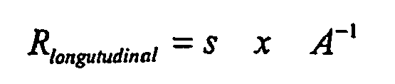
where s is the resistivity of the material of the tube, x is the length of the tube and A is the area of cross-section. If the current through the tube is I, then the potential difference V driving current between the ends of the tube may be calculated from the product of current and resistance i.e.:
- Electric current may also be supplied by applying a voltage between the internal surface of the bore and the external surface of the tube. In this configuration, the effective resistance of the tube, denoted Rradial, may be expressed as:

where α is the electrical conductivity of the tube and ro and rl are the outside and inside radii respectively of the tube. If the current through the wall of the tube is I, then the potential difference may be calculated as before from the product of current and resistance i.e.:
- Table 1 shows calculated values for Rradial and Rlongitudinal for respective tubes of copper and graphite. The dimensions of the tubular forms in Table 1 are appropriate to a discussion of transfer of current in a welding contact tip. Wire of diameter 1.2 mm is one of the most popular sizes for ease of use and productivity. From Table 1, it is evident that radial resistance is approximately an order of magnitude lower than the corresponding value for longitudinal resistance. Accordingly, the most effective current transfer from tube to a wire in the tube would apparently be achieved by establishing intimate contact between the wire and tube over the full length of the tube. Under these idealised conditions, the radial resistance of even a tube of graphite would be as low as 2.4.10-4 Ohms. For a current of 220A, the corresponding potential difference between the outer surface of the tube and the internal surface of the bore would be as low as 0.05V.
Table 1. Calculated values for radial and longitudinal resistances Material Copper Graphite Internal Diameter - mm 1.2 1.2 External Diameter - mm 8 8 Length - mm 25 25 Resistivity - Ohm.m 7.10-8 2.10-5 Conductivity - (Ohm.m)-1 1.4.107 5.104 Rradial - Ohm 8.6.10-7 2.4.10-4 Rlongitudinal - Ohm 3.5.10-5 9.9.10-3 - The longitudinal resistances are typically at least an order of magnitude higher than the corresponding radial values. For copper, the longitudinal resistance is 3.5.10-6 Ohms and therefore minimal. For graphite the longitudinal resistance is 10 milli-ohms. For a current of 220A, the potential difference between the ends of the graphite tube would be 2.2V, which, it will be seen, is significant.
- Resistive heating of the tip by current carried through the tube wall in the radial direction would be minimal for copper and low even for graphite. From Ohm's Law it can also be shown that the potential of the wire emerging from the tube would be, in effect, the same as that of the tube. Any preheating of the wire within the tube would be therefore be minimal, and the corresponding wire melting rate would be at the lower limit of what is possible. It follows that for this example of what would otherwise be considered an example of perfect current transfer, wire melting rate for a given current would be minimised. In other words, it follows that the minimum wire melting rate will be attained if there is perfect contact between wire and tip over the full length of the bore or, as has been shown earlier, if contact is made only at the outlet end.
- In practice, there is some clearance between wire consumable and the bore of the tip. Electrical contact occurs at a number of discrete locations. It is therefore appropriate to consider the consequences of two or more simultaneous contact points of the wire within a contact tip. The simplest example to consider is that of simultaneous contact of the wire with the tip at the inlet end and the outlet end and no intermediate contact. At room temperature, the resistivity of beryllium copper is approximately 7.10-8 ohm.m (see also Table 1). The resistivity of low carbon steel is approximately 1.2.10-7 ohm.m. The ratio of the cross-section of a copper tip to the cross-section of the wire consumable is typically of the order of 50 to 100:1. The combination of low resistivity of the copper tip, coupled with the relatively high cross sectional area of the tip, means that any current in the wire between the inlet and outlet end may be severely reduced by the parallel electrical path in the copper i.e. Rlongitudinal. The effective current supply path would be through the body of the contact tip to the wire at the outlet end of the tip if there is simultaneous contact at the inlet and outlet ends with no intermediate contacts. If initially there were contact at the inlet end only, and subsequent contact at the outlet end, the wire would also cool down as the current in that section of wire was reduced to a minimal value.
- Hence, if there is electrical contact at the outlet end of the tip, it is inevitable, within practical limits, that the effective value for L is approximately 12 mm for an arc length of 8 mm. As has been done earlier, the arc length will be taken to be constant. Examination of wear of copper contact tips shows a key-holing effect at the outlet end indicative of essentially continuous contact with the wire consumable. For contact tips of the type described in
Figure 1 , the effective value for L is 12 mm. This current transfer at the outlet end represents the least productive use of welding current. Although the electrical circuit is completed at the outlet end of the tip, the welding current is conducted through the tip and any preheat of wire within the tip is minimal. - The electrical stability of the contact point of the wire and tip has further implications. If the wire should momentarily fail to make contact with the outlet end of the tip, the voltage at the end of the wire, as it enters the arc region, will change from what could otherwise be a steady value. Arc length depends on arc voltage. Any variation in voltage at the end of the wire will adversely affect arc length, hence arc stability leading subsequently to weld spatter and possible burn-back of the wire consumable. Burn-back may result in welding of the wire to the tip causing immediate failure of the tip.
- For a given current, the fluctuation in voltage of the wire consumable emerging from the tip will depend on the resistivity of the wire. Electrical resistivity is temperature dependent. It is necessary therefore to estimate the average temperature of the wire consumable within the tip. In the above-mentioned text by Radaj it is noted that, for wire electrodes with automatic steady feed, temperature increases nearly linearly from the current input point to the end of the wire. In the immediate vicinity of the arc, the temperature of the wire rises rapidly. The temperature of a droplet of liquid metal attached to the end of the wire is above the melting point of the consumable but would be expected to be below the boiling point of the consumable.
- Given the interpretation of the effects of multiple contacts of the wire within a copper tip and welding experience with copper tips, it is estimated that the average temperature of the wire in the tip is of the order of 100°C for an operating current of 220A. The corresponding wire feed speed would be of the order of 6m/minute and the mode of transfer would be spray transfer, hence the choice of 220A for this particular example. This estimated average temperature rise of 100°C represents an increase in resistivity of steel of approximately 40%. If the room temperature resistivity is 1.2.10-7 ohm.m, the wire diameter is 1.2 mm, the length of the bore in the tip is 25 mm and the average welding current 220A, the potential difference between the ends of a length of wire 25 mm long within the bore of the tip is, from Ohm's Law, approximately 0.8V. Since the voltage drop in the copper tip itself is minimal, the overall fluctuation in voltage associated with resistive heating of the wire emerging from the tip would be approximately 0.8V.
- From manufacturers' data, the power supply voltage for spray transfer at 220A would be of the order of 30V. A fluctuation in voltage of 0.8 V in 30 V could, perhaps, be regarded as insignificant. However, associated with this fluctuation in voltage is the possibility of arcing between the wire emerging from the tip and the exit end of the tip. The arcing arises from switching of current from wire to tip if contact is broken and vice versa when contact is re-established. Arcing may also generate induced voltages at the end of the wire. Furthermore, from the work of Yamada cited earlier, arcing may lead to fusion of the surface of the wire and bore of the tip which, in turn, leads to an adhesive force between wire and tip. Wire feed speed becomes erratic leading to arc instability and spatter.
- It will now be shown that it is possible to achieve a wire preheat within a contact tip substantially higher than say 100°C in the example described above. Suppose that, on entering the tip, the wire makes contact at the inlet end and no further contact with the tip. As explained earlier, the effective value for L is 37 mm of which 25 mm is attained within the bore of the tip. Under these conditions, it is estimated from the above-mentioned work of Radaj that the average temperature of the wire within the tip would be approximately 500°C. From published data for steel, it is estimated that the resistivity of the wire in the tip increases 5 fold to 6.10-7 ohm.m. From Ohm's Law, the voltage drop in the wire within the bore of the tip would be approximately 2.9V for a current of 220A. The corresponding value for power generated in the wire in the tip would be approximately 650W. This represents the most productive mode of current transfer. The electrical circuit is completed at the inlet of the contact tube and the entire welding current is used not only to maintain an electric arc but also to preheat the consumable. If contact at the inlet end could be continuously maintained then fluctuations in voltage and wire feed speed would also be minimised thereby improving the process of droplet formation and transfer. ,
- Suppose also that the tip were made from commercially available graphite with resistivity at the relevant operating temperature of 2.10-5 ohm.m (see Table 1). From Table 1, the longitudinal resistance of a graphite tip of diameter 8 mm would be of the order of 0.01 Ohms and, it can be shown, comparable with the resistance of the wire in the tip. If there were simultaneous contact at the inlet end and the outlet end, the welding current would be divided approximately equally between wire and tip. Though reduced, wire preheat would still be significant.
- If the point of contact were to alternate between inlet end and outlet end, the current distribution would alternate from being carried entirely by the wire consumable to being divided between wire consumable and tip. Arcing between wire and tip would occur as these contacts were made and broken and the extent of local heating in the contact region would depend on the magnitude of the switching current. For metal to metal contact, this type of current switching would be expected to lead to local fusion of the wire and tip and in turn adhesion of the wire to the tip. For a copper tip the problem would be exacerbated since the switching current would be substantially higher than for graphite. For a graphite tip, there is little tendency for the wire to bond to the graphite hence wire feed speed would remain stable. By selecting a graphite material with appropriate resistivity so that the longitudinal resistance of the tip matched the resistance of the wire in the tip, it would also be possible to adequately deliver current to the wire consumable and at the same time to minimise the magnitude of the switching current described above. It is also clear that the resistivity of copper is far too low to allow this type of reduction in switching current.
- Two conclusions emerge from this discussion. If a contact tip is to be made from a material with a resistivity as low as that of copper then the region of current transfer should be as compact as possible to minimise the effects of multiple contacts. If a contact tip is to be made from a material of higher resistivity such as that of graphite, this condition may be relaxed provided that longitudinal tip resistance and wire resistance are comparable.
- It is proposed that this type of matching tip resistance with wire resistance will produce improved stability of arc length and welding current hence performance for GMAW, FCAW and SAW. At the same time, the benefit of wire preheat will be realised i.e. the effective value for the parameter L will be increased. Since the voltage drops in the wire and tip depend not only on resistivity but also on the dimensions of the wire and tip, a more useful conclusion is to propose that, under operating conditions, the resistance of the tip should match the resistance of the wire within the tip beyond the initial entrance length of the tip. Although such a guideline would reduce undesirable effects on arc voltage of multiple electrical contact of the wire within a tip, the guideline relies implicitly on the assumption that the primary contact of wire and tip remains at the inlet of the tip. If there were prolonged contact at, for example, the outlet end, such prolonged contact could ultimately lead to instability due to a reduction in wire melting rate and resistive heating of the tip. The wire melting rate would be reduced because the equivalent value for preheat length L would be reduced.
- Therefore it is preferable that the inlet end of a contact tip be the primary source of current to the wire. One way to achieve this is to minimise the clearance between the wire and the bore of the tip. The combination of low clearance and a slight curvature in the wire, as it is unwound from the spool, enables good electrical contact to be achieved at the inlet end.
- The stability of the primary contact point at the inlet end of the tip could be significantly improved by introducing a slight change in direction in the bore at the inlet end of the tip. The combination of a low clearance between wire and bore with a slight change in direction of the bore would ensure that good contact was achieved at all times and the probability of any significant prolonged contact further in the bore reduced. This type of approach would not generally be used for copper tips. It would lead to a substantial increase in cost since intricate machining could be required during manufacture. Nevertheless there are some precedents. Patent
GB 2074069 - Five properties associated with the material of a tip are particularly desirable to achieve uniform feeding of wire or strip. The first is a low coefficient of friction between the wire or strip and the material of the contact tip. A low coefficient of friction allows a relatively constant wire feed speed to be established as the wire travels through the tip. Ideally the material of the tip would be self-lubricating.
- The second requirement is resistance to elevated temperatures associated with close proximity to the welding arc and heated consumable within the tip. Thus a refractory material is desirable.
- The electrical contact between a consumable wire or strip and the internal surface of the contact tip may not be continuous due, for example, to irregularities in dimensions of the wire or strip. An intermittent electric arc may then be produced inside the tip. Such an arc could locally heat the wire or strip to temperatures approaching or even exceeding the melting point of the consumable. In this event, it is desirable that any liquid metal produced at the surface of the consumable does not readily wet and subsequently bond to the internal surface of the contact tip. Contact tips made from suitable refractory, non-metallic material could be expected to meet this requirement.
- The fourth requirement follows from the earlier discussion of consequences of multiple electrical contacts. That discussion led to the design guideline for resistivity of the material of the contact tip i.e. the resistance of the wire within the tip should match the longitudinal resistance of the tip. For ferrous consumables in copper tips, the mismatch in resistance is about two orders of magnitude. Matching resistances to within a factor of five would be expected to produce substantial reduction in damage due to arcing.
The fifth requirement is that the material of the tip be a good thermal conductor to enable heat produced in the tip, the wire in the tip or absorbed from the arc to be removed by conduction to the contact tip holder. - One material that meets these requirements is graphite and it is possible to design a commercially viable tip by machining the entire contact tip from graphite rod. The machined body preferably would then be electroplated with copper, nickel or chromium over the whole external surface for ease of handling, with the possible exception of the working end that is exposed to the welding arc. This working end preferably would subsequently be coated with an electrically insulating refractory lacquer and, after drying of the lacquer, the bore could be drilled out. An example of the finished product is shown in
Figure 3 . A tip of this type would have a useful lifetime for low current applications associated with dip transfer and therefore the welding of sheet metal. It would have a reduced lifetime for spray transfer. - With more specific reference to
Figure 3 , which is not in accordance with the invention, the overall form of the contact tip is similar to that oftip 10 ofFigure 1 . Corresponding parts have the same reference numerals as used in relation to tip 10, plus 20. Thus, tip 30 ofFigure3 has a threadedsection 32 at its input end and amain body 36 which defines a throughbore 34 extending frominlet end 37 to outlet end 38. Again,section 32 defines aguide 33 which leads to inlet end 37 ofbore 34. Around the working end ofbody 36,tip 30 is provided with an electrically insulating refractory lacquer coating (not shown). - While, as indicated, it is possible to make
tip 30 from graphite, as shown inFigure 3 , it is found that the tip as described to this stage is not satisfactory. This is because the contact area between the electrode and the tip at the inlet end of the tip may be insufficient to transfer the bulk of the current required to achieve the desired wire melting rate. Current flow from thebody 36 to the electrode will tend to be from two or more contact points. Although the effects of multiple contacts in graphite may not be as severe as they would be in copper, with a graphite contact tip as inFigure 3 , it is necessary to provide means which ensures a primary contact point within bore 34 which is at or adjacent to end 37, such that this contact point has less contact resistance than any other contact point further alongbore 34. InFigure 3 , this is provided by contactingmeans 40. -
Means 40 is provided in aradial passage 42 which communicates with bore at or adjacent to end 37 ofbore 34. I npassage 42, means 40 includes aplunger member 43 which is lightly biased by aspring 44, such as a coil spring, retained inpassage 42 by acap 45 secured in the outer end ofpassage 42.Spring 44biases plunger member 43 towardsbore 34, such that a leading end of member protrudes intobore 34. The arrangement is such that, with an electrode passing throughbore 34, the protruding end ofmember 43 is able to bear against the electrode, to bring the electrode into sliding contact withbody 36, at the side ofbore 34 remote from means 40. Thus, means 40 is able to achieve such contact which minimises contact resistance between the electrode andbody 36, and thereby establish a point of primary electrical contact from which resistance heating of the electrode is able to be maintained, while presenting only slight resistance to movement of the electrode throughbore 34. - The
plunger member 43 ofmeans 40 may be formed of an electrically insulating material, or of an electrically conductive material. - While the description of
Figure 3 is with reference to contacttip 30 being made of graphite, the arrangement shown with provision ofmeans 40 is suitable for use with contact tips of other materials. Thus, instead of graphite per se,contact tip 30 may be made of a graphite composite, such as graphite/silicon carbide composite. Alternatively,tip 30 may be made of copper or a copper alloy. In a further useful alternative, which enables cost savings over the use of copper,tip 30 can be iron or steel. In each case, means 40 provides a practical way of ensuring a required primary contact point. However, even withmeans 40, it is preferable fortip 30 to be relatively short, such that bore 34 is about 12 mm in length. - A more robust monolithic version, suitable also for spray transfer, could be made from composite materials such as silicon carbide-graphite composite materials. The proportions of silicon carbide and graphite could be chosen to meet the guideline for resistivity. The raw materials for these types of composite materials are generally in powder form. It is possible therefore to mould a bore that has a slight change in direction at the inlet end. In this way a very reliable current delivery point at the entrance of the tip would enhance the performance. In a further enhancement, the composition could be functionally graded to achieve high electrical and thermal conductivity in the threaded end up to the inlet of the bore, then gradually reducing these conductivities to the end of the tip. The combination of silicon carbide and graphite is presented here only by way of example. In particular, graphite-metal and metal-ceramic composites (i. e. cermets) could also be used to manufacture contact tips.
- There are two key electrical requirements for optimum performance with a welding power supply. The first is that current be supplied from the power supply to the wire consumable via a continuous, stable path of very low electrical resistance so as to minimise transient current and voltage variations in the welding circuit. The second requirement is to establish a well-defined contact area so that the effective value for the parameter L is stable with time and is reproducible from one welding operation to another. If the main body of the tip is to be made of copper or other material of very low resistivity, then the primary contact area should be as short as possible.
-
Figure 4 shows an example of acontact tip 50, also not according to the invention, but that essentially meets these requirements. Thisparticular tip 50 is designed for GMAW. A wire consumable used withtip 50 may be of diameter 0.9 mm. The overall length of thetip 50 may be approximately 38 mm and in the range 35 to 40 mm typical of commercially available contact tips designed for 0.9 mm wire. However the form oftip 50 is suitable for wire diameters other than 0.9 mm. Thetip 50 has a design enabling it to be a direct replacement for a conventional tip. - The
contact tip 50 is of annular cross-section and defines abore 52 through which the electrode is able to pass. Thetip 50 has three sections each of which defines a respective part ofbore 52. Thefirst section 54 extends from theinlet end 56 oftip 50 over a minor part of its overall length. Thesection 54 is of lesser diameter than the remainder of the length oftip 50 and is externally threaded at 57 to enabletip 50 to be screwed into a contact tip holder (not shown) of a welding torch (also not shown). Withinsection 54, bore 52 is counter-bored to provide a larger diameter inlet end 58 from which bore 52 has a frusto-conical taper 59 to in small diameter form beyondsection 54. - The
second section 60 oftip 50 is formed integrally withsection 54. Over a short distance fromtaper 59 of, for example, about 5 mm, bore 52 has alength 61 which is defined bysection 60 and is of a minimum diameter. Fromlength 61, bore 52 has a remaininglength 62 defined by athird section 64 oftip 50.Section 64 is an annular insert withinsection 60. Thesection 60 is counter-bored fromend 65 oftip 50 to receivesection 64. Insection 60,section 64 may be a firm fit therein, orsection 64 may be retained by a ceramic paste. - As indicated,
tip 50 may have an overall length of about 38 mm and be designed for use with 0.9 mm diameter wire consumable electrode. In that context,sections inlet end 58, bore 52 may have a diameter of about 4 mm, reducing to 1.0 mm over itslength 61 to provide a 0.1 mm clearance for 0.9 mm consumable. Over itslength 62, bore 52 may have a diameter providing a clearance of from 0.5 to 1.0 mm for the consumable. - The first and
second sections contact tip 50 is of a metal having a relatively high level of electrical conductivity. Thethird section 64 is made of non-metallic, electrically insulating material. The first andsecond sections third section 64 preferably is of a refractory, electrically insulating material such as alumina or a machinable, ceramic material. However, other electrically conductive and insulating materials can be used. - The diameter of
length 62 of thebore 52 is indicated as approximately 0.5 to 1.0 mm greater than the diameter of the wire consumable. The clearance is not critical but an excessive clearance insection 64 is not recommended in order to avoid wire wander during welding. Too tight a fit introduces friction between the wire consumable and ceramic and can adversely affect feedability of the wire consumable. Also,section 64 most preferably is a non-porous ceramic. It is found that porous ceramic can contain chemically-bound water and/or transmit water from ceramic paste by whichsection 64 may be retained. Alternatively, the end of the copper tube may be peened to retain the ceramic insert. - The
inlet end 58 and taper 59 ofbore 52 serve to guide a wire consumable throughlengths bore 52. Thesection 54 oftip 50 is to provide that guidance and to enable thetip 50 to be mounted in the holder of a torch, rather than to provide electrical contact with the consumable. Such contact is made inbore 52, beyondsection 54 and, for the purpose of making electrical contact, the effective inlet end ofbore 52 is at the junction betweentaper 59 andlength 61. - A key feature of the
contact tip 50 is apressure point 66 whereby wire entering the tip is pressed against a surface defining thebore 52. Thepressure point 66 enables current to be transferred from the bore of the tip to the wire in a well defined area of the tip. Accordingly the value of the parameter L referred to earlier is also well defined. In this case the value for the parameter L is the distance from the pressure point to the welding arc at the end of the wire. - All contact tips are designed to be used in conjunction with a contact tip holder in a welding torch. In use, the tip is screwed into the contact tip holder such that the rear surface of the body of the tip is in firm contact with the mating surface of the contact tip holder. This provides mechanical stability as well, as a path for heat generated in the contact tip to be conducted to the contact tip holder and subsequently removed from the body of the torch by air or water cooling. One key feature that is common to the design of a majority of the tips shown herein is the location of the current delivery area within the tip. To maximise preheat length, the current delivery area should be located in the vicinity of the effective inlet end of the bore. To assist with removal of heat generated within the contact area as well as heat conducted along the wire within the tip, the current delivery area in tips shown herein is preferably located within the main body of the tip rather than in the threaded inlet end. Although preheat length is thereby reduced, this disadvantage is offset by lower operating temperatures and therefore more reliable overall performance.
- A pressure point within a tip may be made in a number of ways. The
pressure point 66 shown inFigure 4 is made by drilling aradial hole 67 in thesection 64 of thetip 50 up to thelength 61 of thebore 52. For the dimensions of thetip 50 detailed above, a suitable diameter of theradial hole 67 is about 3 mm. Thishole 67 then is tapped so that aset screw 68 may be inserted therein. The purpose of theset screw 68 is to acompress plug 69 of a small amount of a soft, refractory material at the leading end ofscrew 68 against the wire entering the tip thereby pressing the wire to one side ofbore length 61. Examples of suitable materials forplug 69 are Teflon, graphite-loaded Teflon and graphite tape. These materials are stable at elevated temperatures and sufficiently soft to conform to the shape of the wire in the bore and thereby achieve a soft, low friction, generally continuous, mechanical, sliding contact with the wire. Consequently, in spite of introducing frictional force at the pressure point, the feed force required to push the wire through the tip is not excessive or detrimental to feedability of the wire. - A tip of the form described in
Figure 4 has been constructed and its performance evaluated in laboratory tests. Compared with conventional copper tips of similar overall dimensions operating under essentially the same welding conditions (i.e. voltage and wire feed speed) it was found that, for any given wire melting rate, current and therefore heat input were reduced. The value for L for thetip 50 shown inFigure 4 is substantially higher than the corresponding value for L for a conventional copper tip. The electric current in the wire preheats a greater length of wire than that in a conventional copper tip. Referring to the formula for wire melting rate it is evident that, for a given value for W, the current required to maintain that value of W is reduced if the effective value for L can be increased. Furthermore welding fume was also reduced substantially. The reduction in fume is believed to arise from improved feedability and also the reduced influence of the electric arc. The greater the value for L, the greater the contribution of the resistive heating by current in the wire to the melting rate W. The role of the electric arc, which is characterised by extremely high temperature, is reduced. Accordingly it is expected that the temperature of droplets of metal transferred from the end of the wire to the workpiece will be lower than the corresponding temperatures for conventional copper tips operating at the same wire melting rate. Consequently evaporation of metal from the end of the wire exposed to the arc is reduced. Since evaporation of metal from the end of the wire is a significant source of fume, the total amount of fume generated for a given wire melting rate W is therefore reduced. There is a further and major reduction in fume generated due to improved wire feedability. Weld spatter was also substantially reduced. It is believed that this reduction in spatter is due in part to the reduced droplet temperature, and therefore the fluidity, of molten metal at the end of the wire consumable. Furthermore any spatter produced is less likely to adhere to the workpiece because the probability of bonding between liquid metal droplets and a relatively cold workpiece decreases as the temperature of the droplets of spatter decrease. - There was a peculiarity noted in relation to the operation of the tip described in
Figure 4 . This was identified following examination of the wire in the torch. At the conclusion of a welding pass, a length of wire (typically one metre) would be fed through the tip at the end of the torch with the welding current switched off. At random locations along the length of wire fed out, it was observed that the surface of the wire had been discoloured by arcing that had occurred in the region of the torch between the feed rolls and the contact tip i.e. prior to the wire entering the tip. This arcing had occurred during the welding operation immediately preceding the inspection. Now the wire within the torch is guided by a liner, usually of steel wound in the form of a spiral with closely spaced turns. The liner extends from the feed rolls in the welding machine to the contact tip and is generally in contact with the tip. - It was concluded that arcing had occurred in the preceding welding operation during short moments in time (perhaps microseconds or less) when the wire in the contact tip did not contact the bore of the tip. Such contact failure could be due to local irregularity in wire diameter, oxide deposits on the surface of the wire and lateral movement of the wire in the tip. During these short moments, when there was an open electrical circuit within the tip, other higher resistance circuits external to the tip could and would be formed with temporary electric arcs completing those circuits. An example of one of these undesirable current paths would be from the output of the power supply to contact tip to the wire liner ahead of the contact tip to a section of wire preceding the tip then through the wire in the tip and emerging beyond the tip to the welding arc and ending at the workpiece. Ultimately such intermittent arcing may destroy the liner. It may also lead to welding failure if the wire within the torch welds itself to the liner. A benefit would result if the steel liner were to be replaced with an insulating one, such as one of Teflon. Arcing would still be likely to occur somewhere in the welding circuit but with unpredictable and undesirable consequences. A better approach for improving on
tip 50 ofFigure 4 would be to eliminate the open circuit condition. - Since metal transfer was occurring apparently satisfactorily while welding with tips of the form described in
Figure 4 , it was also concluded that, for most of the welding time, current transfer had occurred within the respective tip at the pressure point. One way to avoid an open circuit condition would be to install a second pressure point immediately adjacent to the first pressure point. In effect both contacts would be closed most of the time. Should one of the contact points be open, current transfer would be made through the other. Since the pressure points are adjacent, they would operate at essentially the same electrical potential, so that the welding arc would be stable. Current transfer would therefore be continuous and, in the absence of voltage and current transients associated with supply of current to the wire, there would be a substantial reduction in spattering. Fume generation would be reduced for reasons already described. In summary, the probability that both contact points could be simultaneously open is negligible. - A
tip 50a with two pressure points was therefore constructed and is shown inFigure 5 , also not according to the invention. This is substantially the same astip 50 ofFigure 4 , except for there being two pressure points and corresponding components having the same reference plus "a". There are two threadedholes 67a, each with ascrew 68a having a plug 69a. It was found that the operation of thetip 50a as shown inFigure 5 is superior to conventional copper tips. There was no evidence of arcing in the wire in the torch prior to entering the tip. During welding, the arc length was stable. In developing the tip described inFigure 5 , a new principle had been established for GMAW. With respect to a sliding electrical contact, optimum current transfer may be achieved by supplying current at two (or more) current delivery points operating at essentially the same potential. If these current delivery points are thought of as equivalent to electrical switches, then optimum performance will be attained if the switches are designed to function in a normally closed condition such that the probability of both being open simultaneously is negligible. If the switches are designed to operate at the same potential, then the performance of an external circuit relying on these switches with both switches closed cannot be distinguished from the performance with only one of the pair closed. The external circuit will therefore not be subject to transient variations associated with short-term variations in current transfer in one of the contacts. - Any other transients observed will be intrinsic to the process. In the case of GMAW, droplet transfer will lead to inescapable transients but the droplet transfer will occur under essentially ideal conditions and the true capability of GMAW can and will be realised.
- There is an additional significant benefit associated with using two current delivery points operating at effectively the same electrical potential. This benefit is related to the phenomenon of burn-back of the electrode. Under stable operating conditions arc length is typically less than half of the distance between the end of the contact tip and the workpiece. If the electrical contact resistance between the wire and the tip were to increase due, for example, to a local variation in wire diameter then, under conditions of constant voltage, the current in the wire will decrease. In turn this will lead to a sudden decrease in wire melting rate and a corresponding increase in arc length. Under certain conditions the arc length can exceed the stand off distance between the end of contact tip and the workpiece. The electrode is said to burn back inside the tip and may either be welded to the tip or become wedged in the bore of the tip. Usually the damage to the tip is irreparable. The use of two or more pressure points reduces the possibility of burn back arising from intermittent high electrical contact resistance between wire and tip since it is unlikely for both contacts to simultaneously have a high resistance.
- There is another important difference between the tips shown in
Figures 4 and5 . InFigure 4 , current is transferred to the wire consumable over a length of copper bore of about 5 mm i.e. inlength 61 ofbore 52 oftip 50. The length of the ceramic insert is about 23 mm and a lower limit for the length of wire preheated inside the tip is therefore 23 mm. InFigure 5 , insert section 64a is shorter thansection 64 ofFigure 4 by about 5 mm. Thus, current is transferred to the wire consumable over a large proportion oflength 61a of copper bore of 10 mm. A lower limit for the length of wire preheated inside the tip is therefore 18 mm. It is evident that the larger the length of bore over which current is delivered, the lower will be the wire preheat length within the tip if the total tip length is held constant. The current delivery area is subject to wear and it is reasonable to assume that a small current contact area will wear a faster rate than a large contact area. There will therefore be a balance between performance as measured by current reduction for a given wire melting rate and tip lifetime. As a general guideline, it would be undesirable to make the current contact length a substantial proportion of the total length of a tip. In this respect there is a further important consideration. One of the most important measures of productivity is wire feed speed. The contact area represents an obstruction to the smooth passage of wire through the tip. It is expected that the smaller the contact area, the smaller the obstruction and therefore the higher is the maximum operating wire feed speed. The tip shown inFigure 5 has a relatively small contact area in comparison with the tip shown inFigure 1 . The tip shown inFigure 5 can be reliably operated at a wire feed speed of 20 m/minute. This is well in excess of the manufacturer's recommendation for wire consumable of diameter 0.9 mm. - The means of constructing a pressure point in which the electrode is forced into light sliding contact in the first part of the metal bore, with the material defining the bore, may take a variety of forms. In the specific example of
Figure 3 , the electrode is resiliently biased into light sliding contact. In that arrangement, the body of the contact tip defines a passage which extends laterally with respect to, and communicates with the first part of, the bore. The passage houses a contact member and a spring acting to force the contact member into the bore for engaging the electrode. The spring acts through the contact member to urge the electrode into light sliding contact with a side of the bore remote from the passage. The advantage of a spring-loaded contact is that one tip could be designed to accommodate a range of wire sizes. It would for example be possible to design one tip to function with wires of diameter in the range 0.9 mm to 1.2 mm. - Wire consumable for GMAW is supplied in two types of packages. The most common package is a compact spool of capacity typically about 15 kg. The wire has an intrinsic curvature associated with deformation induced in winding the wire onto the spool. This curvature is characterised by two parameters. One is referred to as the cast of the electrode and is the diameter of one loop of unrestrained wire unwound from the spool. The other parameter is referred to as the helix and is the vertical distance that the end of a single loop of wire is above the beginning of the loop. The second type of package may be referred to as an "autopak" with a capacity to hold at least 300 kg of wire, compactly wound and housed in a portable cardboard drum.
- The curvature of the wire supplied from either type of package allows the wire to bed into the material of the contact tip. This can assist in providing a reliable electrical contact within the tip. It does also lead to wear of the contact tip and ultimately to poor performance. With respect to tips of the form described in
Figures 4 and5 , the optimum angular location of the pressure point or points is to coincide with the convex curvature of the wire as it passes through the tip. - The use of pressure points as described in
Figures 4 and5 represents the introduction of mechanical constraints to the movement of wire through the tip. However, we have found that it is possible to reproduce the same type of performance as obtained from tips of the form shown inFigure 5 by a different application of the principle of supplying two, normally closed, current contact points, but without directly constraining the movement of the wire through the tip. -
Figure 6 shows an example of such a contact tip which provides an example of this and according to the present invention. Components corresponding to those ofcontact tip 50 ofFigure 4 have the same reference numeral plus "b". Thetip 50b is designed for wire of diameter 0.9 mm but, again, the design principles presented here are not restricted to wire of diameter 0.9 mm. Thetip 50b has a body which definessections section 54b defines a taperedconical guide 59b to facilitate smooth entry of the wire into thebore 52b. The body also defines ashort inlet length 61b ofbore 52b. The section 64b comprises two inserts which together definelength 62b ofbore 52b. Thefirst insert 70 is of graphite, preferably a fine-grained, extruded graphite, which defines afirst part length 62b ofbore 52b. The second insert is a length ofceramic tube 72, such as alumina, glued inside the copper alloy body with refractory cement. Theceramic tube 72 acts as a guide for the wire emerging from the tip and defines anoutlet end 65b ofcontact tip 50b. - The coefficient of expansion of metals such as copper is generally higher than the coefficient of expansion of ceramic materials. For applications involving high operating tip temperatures the insert comprising
ceramic tube 72 may become loose in the copper body. To preventtube 72 moving it may be necessary to peen the copper body atend 65b to prevent the insert from becoming dislodged. Alternatively the insert could have an external thread and be screwed into the copper body which would therefore be modified to accept such an insert. - During welding, the wire enters the
tip 50b through theconical inlet section 54b and makes its first low resistance contact with thetip 50b at theinlet end part 61 b of thebore 52b in the copper alloy body. The diameter of thebore part 61 b is approximately 1.05 mm, hence the clearance between the wire and borepart 61 b is approximately 0.15 mm. This is sufficient to allow smooth entry of the wire into and through thebore 52b of thetip 50b. A second low resistance contact area is at the beginning of thebore part 62b in thegraphite insert 70. The graphite is - softer than copper and the wire beds itself into thebore part 62b of thegraphite insert 70, providing a second current contact which may be thought of as equivalent to a normally closed contact. Thebore part 62b in thegraphite insert 70 is of approximately 0.95 mm diameter i.e. approximately 0.1 mm less than that of thebore part 61 b in the copper body, to accommodate this bedding in process. For anew tip 50b, the bedding in occurs almost immediately after welding is commenced for the first time and does not significantly detract from overall performance either initially or in subsequent use. The diameter of thebore part 62b in thegraphite insert 70 is not made significantly less than 0.95 mm so as to avoid a tight fit in the graphite. As detailed above, the radial electrical resistance of even a relatively poor conductor such as graphite of the type used in the construction of the tip ofFigure 6 is extremely low. A tight fit between the wire and thebore 52b in thegraphite insert 70 could enable thegraphite insert 70 to electrically short circuit the current in the wire with the graphite insert leading to reduction in preheat length L and also to variation in voltage of the wire emerging from the graphite insert. In turn this would lead to instability in arc voltage and arc length and ultimately to welding defects. - The external diameter of the
graphite insert 70 is such that there is an interference fit between theinsert 70 and thesection 60b of the copper alloy body. Electrical contact between thegraphite insert 70 and copperalloy body section 60b is further improved by the use of a thin film of copper loaded, electrically conducting grease applied to the external surface of theinsert 70 during assembly. This grease also facilitates assembly of thecomposite tip 50b. Since there is good electrical contact between thegraphite insert 70 and the copperalloy body section 60b, the electrical potentials of the two current delivery points i.e. the first one at the beginning of thebore part 61 b and the second one of the beginning of thebore part 62b, are essentially the same. The length of thegraphite insert 70 inFigure 6 is usually in the range of 11 mm to 13 mm to reduce the possibility of the wire bedding in at other locations substantially distant from the entry point in the graphite. This length has been determined by experiment and is long enough to allow good electrical contact as well as ease of handling during assembly of the tip. A practical lower limit for the length of the insert would be approximately 5 mm. With this combination of measures it has been possible to establish the equivalent of two normally closed current contact points operating at essentially the same potential. Accordingly the performance of thetip 50b during welding is comparable to that of thetip 50a shown inFigure 5 and is superior to conventional copper tips with respect to current for a given wire melting rate. Spatter is minimised and fume generation reduced substantially. - As indicated,
tip 50b has a restriction of the length of thegraphite insert 70 to prevent the wire in the graphite insert bedding in at more than one location. This bedding in process depends on the stiffness of the wire. One of the most important variables determining stiffness is wire diameter, the greater the diameter the greater the stiffness. For wires of diameter less than 1.6 mm there is a tendency for the wire to weakly bed into the graphite at more than one location. As the current delivery point within the graphite insert changes from one location to another, current and potential in the wire emerging from the tip both change. Arc length is therefore unstable and the wire melting rate is variable. This leads to defects in the weld. It is therefore highly desirable to restrict the length of the graphite insert for such wires to eliminate the possibility of multiple current contact points in the graphite insert. - One of the key performance indicators of a welding tip is the lifetime of the tip. While the
tip 50b ofFigure 6 is functioning correctly, the wire consumable slides over the short length of copper (in this case approximately 4 mm) in thebore part 61 b of thetip 50b and then over a region of graphite adjacent to the junction between thegraphite insert 70 and the end of thebore part 61 b insection 54b of the body of copper. There is sliding friction between the wire consumable and each of the copper borepart 61 b and thegraphite insert 70. Graphite can wear away faster than copper, but the overall wear rate of the copper-graphite combination is controlled by the wear rate of the copper. Ultimately the entrance to bore 52b of thetip 50b becomes elliptical and the electrical contact between the wire and the copper body atsection 54b of the tip becomes mechanically and electrically unstable. The effective current delivery area can move from the junction between the graphite and copper to a region within thegraphite insert 70. In effect the wire preheat length is reduced and therefore the current required to maintain a particular wire melting rate is increased. This is therefore a sign of deterioration in performance of the tip. There is also an increase in the level of spatter since the probability of an open circuit condition, albeit momentary, is increased. - For a tip of the type shown in
Figure 6 , a lifetime of approximately 3 hours is possible. Here the term lifetime is used to represent "arc-on" time, that is, the time that arc welding is in progress. The welding conditions that applied in a lifetime test were for a copper coated steel wire of diameter 0.9 mm, a wire melting rate of approximately 14 m/minute, a current of 165A and a voltage of approximately 30V. A pulsed power supply was used in conjunction with a robotic torch. This was to simulate conditions that are relevant to robotic welding in automotive applications. - Although the lifetime test has been carried out at the upper end of the wire feed speed range for 0.9 mm wire consumable, it is important to appreciate that this composite tip shows exceptional stability at low wire feed speeds of the order of 2 metes per minute. These wire feed speeds coincide with dip transfer and are particularly important in the welding of thin metal sheet. The combination of improved feedability, reduced operating current relative to conventional technology, reduced risk of burn-through and reduction of spatter are key features of the operation of this tip.
- The graphite insert in the tip of
Figure 6 serves an additional purpose. In the event that the electrode burns back inside the tip, liquid metal at the end of the wire may solidify within the ceramic insert or, failing that, within the graphite insert. The solidified metal is unlikely to bond to the graphite insert and the function of the tip may be restored pushing the electrode out of the tip. In a conventional copper tip, burn-back usually causes irreparable damage to the bore of the tip with the end of the electrode permanently welded to the bore of the tip. - Having verified these design principles for contact tips it is now possible to design tips specifically for high deposition rates in spray transfer. For simplicity but without loss of generality, non-pulsed GMAW will be considered. The mechanisms for dip and spray transfer are explained more fully above. However, in brief, spray transfer is characterised by detachment of liquid metal droplets from the end of the wire through the arc to the work piece. The end of the wire does not contact the weld bead. High deposition rates at lower currents may be attained by increasing the length of the ceramic guide tube in the copper alloy body of the tip.
-
Figures 7 and 8 illustrate examples ofrespective tips tips tip 50 ofFigure 4 have the same reference numeral plus "c" and "d", respectively. For these tips, the restriction of total tip length of 35 to 40 mm has been removed. The performance of atip 50c as shown inFigure 7 has been verified by experiment. The construction of this will be apparent from the description ofFigure 6 since the materials are the same and the principal differences are solely in relation to longitudinal dimensions. Thus, thetip 50c has an overall length of 68 mm,graphite insert 70c is approximately 13 mm long, whileceramic insert 72c is 44 mm long. The diameter ofbore 52c over its successive sections defined by copper alloy, graphite and ceramic are as detailed fortip 50b ofFigure 6 , astip 50c also was made for use with 0.9 mm diameter wire. - With
tip 50c, using copper coated wire 0.9 mm diameter, a wire melting rate of approximately 16.5 m/minute has been attained with a current as low as 120A. The wire feed speed of 16.5m/minute is already the maximum wire feed speed of most commercially available conventional machines. With a conventional copper tip the wire melting rate of 16.5 m/minute is impractical since the current required to achieve that wire melting rate would be above the recommended maximum current for that consumable. - At this stage it is not known what is the practical upper limit for increasing electrode extension. The issue is complicated by limitations inherent in current power sources. Extended wire preheat lengths, particularly of the order of 100 mm, may require higher operating voltages than are generally available and therefore in order to achieve the projected very high wire melting rates it is anticipated that a new high-speed wire feed unit with corresponding power source will have to be acquired Nevertheless the
tip 50d shown inFigure 8 was constructed. The construction oftip 50d also will be apparent fromFigure 6 . In this case, thetip 50d has an overall length of 112 mm,graphite insert 70d is 13 cm long, whileceramic insert 72d is 88 mm long. Again, the diameters of successive sections ofbore 52d are as detailed fortip 50b ofFigure 6 . The effective preheat length is approximately 100 mm and the end of the wire becomes very soft and difficult to feed uniformly during welding. The quality of the welds has been inconsistent and it is considered that, taking into account limitations in existing power source technology, the preheat length of 100 mm is a practical upper limit for wire of diameter 0.9 mm. Nevertheless experience with the tips shown inFigures 7 and 8 indicate that a preheat length of the order of 100 mm would be practicable for wires of diameter greater than 1.2 mm. - It is appreciated that ceramic extension pieces have been made to increase the electrode extension for conventional copper tips. However, the relatively poor feedability associated with conventional copper tips and the softness of the preheated length of welding wire has prevented the type of benefits now available from having been realised.
- Although the
tips Figures 7 and 8 are composite tips comprising a copper alloy body, graphite insert and ceramic guide tube, the same design principle can be applied to manufacture long tips based on two pressure points as described in relation to tip 50a ofFigure 5 . It is also important to appreciate that the metal body need not be of copper alloy. Steel is acceptable. The main proviso with the use of steel is that a refractory enamel coating would be applied to the external surface of the tip to minimise adhesion of any spatter. - It is also important to appreciate that more than two pressure point may be used. For very stiff wires of diameter 3 mm or more it may be advantageous to have three pressure points closely spaced along the axis of the bore but displaced radially at intervals of 120 degrees. In this way it would be expected that two of the three would always be in contact with the wire consumable.
- Given the limitations on wire feed speed in currently available machines, to achieve higher deposition rates it is necessary to use wire consumables of diameter greater than 0.9 mm. The same design principles apply, and the key design guideline is to limit the length of the graphite insert so as to prevent the wire from bedding in at two distinct areas within the graphite. The stiffness of a wire depends on its diameter. As the diameter increases, so does the stiffness. With the increase in stiffness there is an increase in the wear rate of the contact tip. For a contact tip of the type shown in
Figure 6 , the controlling wear mechanism is the wear rate of the copper at the entrance of the tip. The tip lifetime may be increased by increasing the length of the copper entry length from for example 4 mm as shown inFigure 6 to approximately 10 mm. The longer length of copper will spread the load imposed by the curvature in the wire consumable and therefore the wear rate of the copper contact area will be reduced. The disadvantage of increasing the copper contact length is the introduction of short circuits in the wire sliding over that copper entry length whenever the wire makes good contact at more than one point. This leads to erosion of copper and reduction of feedability due to adhesion of the wire and the copper part of the bore. Another disadvantage is the reduction of length of wire preheated within the tip. - A practical alternative to increasing excessively the contact entry length is to use a different combination of materials at the entrance of the tip.
Figure 9 shows one example successfully trialled for use at high wire feed speeds and a wire consumable of diameter 1.2 mm. InFigure 9 there is shown acontact tip 50e in which components corresponding to those oftip 50 ofFigure 4 have the same reference numeral plus "e". Thetip 50e has a body which definessections section 54e includes an insert 74 within the copper body. The insert 74 is of annular form and of sintered tungsten. The insert 74 defines thetaper 59e and defines a 3 mm long inlet part ofbore length 61 e ofbore 52e. The outside diameter of the tungsten insert 74 is approximately 0.05 mm larger than the recess in the copper part ofsection 54e and the insert 74 is pressed into the copper body during assembly of the tip. The tungsten insert provides the first of two current delivery components with tungsten being chosen for its resistance to sliding wear by the wire consumable Immediately following the tungsten insert 74, there is an 8 mmpart bore length 61 e defined by copper. Relative to tungsten, the copper has low resistance to sliding wear and, in this arrangement, the copper has in effect replaced the graphite insert shown in tips of the type shown inFigure 6 . Thesection 64e of the tip is an 18mm long insert of machineable ceramic. For wire of diameter 1.2 mm the diameter of the part ofbore length 61 e in the tungsten insert 74 is approximately 1.3 mm, the diameter of the part of thebore length 61 e of copper is approximately 1.25 mm and the diameter of thebore length 62e in the ceramic insert is ofsection 64e approximately 2.0 mm. As wire enters the tip it slides over the tungsten insert 74 and beds itself into the copper and is subsequently guided out of the tip through theceramic section 64e. The step change in diameter of the conducting part of the bore is small but significant. The step is large enough to establish a well defined contact area in the copper at or beyond the step. The precise location depends on the clearance between wire and bore, the wire stiffness and curvature. The back-up current delivery area is the tungsten insert in the region adjacent to the step. Both current delivery areas operate at essentially the same potential and an open circuit condition is unlikely. The preheat length is well defined and the wire melting rate uniform. Any obstruction to the smooth passage of wire is small and high wire feed speeds are therefore attainable. The lifetime of this type of tip is controlled by the wear rate of the tungsten. For non-pulsed GMAW and a wire feed speed of approximately 15m/minute, the current required to maintain that melting rate is approximately 290A for an applied voltage of 34V. For a conventional copper tip at the same wire feed speed the current required is approximately 400A. The lifetime of the tip even at this high wire feed speed is approximately 2 hours. Tungsten is difficult to machine and is relatively expensive, and insert 74 therefore would preferably be sintered to as close to its final dimensions as possible. Other viable alternatives are hardenable carbon steels, silver steel, white irons and nickel and cobalt based hardfacing alloys. One tool steel, namely silver steel, has been found to be both effective and convenient to use. This is silver steel which is a 1% carbon tool steel supplied centreless ground to close tolerances. It is machineable and may be substantially hardened by heat treatment after machining. It has been successfully used as an alternative to tungsten both in its original as supplied condition and in its heat treated condition. - One other option to a tungsten copper combination as described in
Figure 9 is to have an insert of silver steel in a body of mild steel. This would provide a good match between the coefficients of thermal expansion between the body and the insert. - At high wire feed speeds there is evidence of accelerated adhesive wear between copper coated steel consumables and copper tips. Since the environment within a tip is essentially chemically inert, it is difficult for an oxide film to form on the exposed part of the copper bore and the wire itself. In the absence of surface oxide films, copper bonds to copper and there is accelerated wear as wire is pushed through the tip. A viable alternative to copper is grey cast iron. The graphite in grey cast iron ensures that the alloy is self-lubricating. Although certain grades of grey cast iron are machineable, a contact tip body of grey cast iron would be brittle and have a tendency to crack under tensile stress during the operation of inserting, for example a tight-fitting (preferably an interference fit) tungsten insert. Nevertheless grey cast iron can be used as an insert to replace the copper contact area in a composite tip. An example of such a combination would be a tip comprising a copper body with inserts of a heat treated silver steel, followed by grey cast iron, followed by machineable ceramic.
-
Figure 10 shows a tip which is similar totip 50e ofFigure 9 and, in this case, the references are as forFigure 4 plus "f". Intip 50f ofFigure 9 , aninsert 78 is of cast iron instead of copper and insert 76 is of silver steel, whilesection 64f again comprises an insert of a machineable ceramic. After machining, insert 78 was heat treated to increase hardness and wear resistance. - It is important to appreciate that electrical contact resistance between a conductive insert and metal body of a tip must be minimised. For a contact resistance of 1 milli-ohm, for example, and a current of 300A, the resistive heating in the contact area would be as high as 90W. This would result in excessive heating of the tip leading to poor performance and reduced lifetime. It is therefore recommended that the fit between an insert and metal body of a tip be as tight (preferably an interference fit) as possible and that electrically conductive paste be used to fill any space between the outer surface of an insert and the inner mating surface of the metal body. This is especially critical if more than one insert is used as is the case in the
tip 50f ofFigure 10 . An alternative to electrically conductive paste is to braze or solder a conductive insert in the metal body of the tip and thereby ensure that any electrical resistance between the body of the tip and a conductive insert is very low. Although the examples given apply to wire consumables of diameter 1.2 mm, they may be readily applied for consumables of diameter greater or less than 1.2 mm. The primary requirements are to establish a well defined and compact current delivery area and to do so in a way that minimises the possibility of an open circuit condition. This latter requirement can be achieved by the use of pressure points. It can also be achieved by selecting suitable combinations of electrically conducting material pairs such that one member of such a pair has high resistance to sliding wear and the other member has a relatively low resistance to sliding wear. Stable electrical contact is achieved and maintained by the wire bedding into the material of relatively high wear with the overall wear rate and therefore tip lifetime controlled by the properties of the wear resistant member. The possibility of an open circuit can also be reduced by using a step change in the diameter of the bore in which the conducting region is made of a single material. In this case the wire beds into the material of the step thereby establishing a well defined current path of low resistance relative to other possible paths within the conducting part of the bore. - In industrial situations where, for example, it becomes necessary to weld downwards in a vertically down orientation of the torch, weld spatter is inevitable since current continuity from the consumable to the work piece is compromised by the downward flow of the weld pool. Spatter may therefore be created and may also adhere to the copper body of the tip and also to the exposed surface of the ceramic insert. Ultimately the spatter build up may form a continuous electrical path from the wire emerging from the tip to the copper body of the tip. This will lead to significant deterioration in the performance of the tip. Accordingly tip performance and lifetime may be improved by coating the external surface of the body of the tip with a refractory enamel material, such as a high temperature engine enamel, to reduce the adherence of spatter and to prevent an electrical path being formed connecting the wire emerging from the tip to the body of the tip. One alternative to coating with engine enamel is to spray the external surface of the body of the tip with an electrically insulating refractory material such as alumina. Another alternative is to nickel plate the external surface of the body of the tip since weld spatter is only weakly adherent to nickel coatings.
- The problem of spatter build up may be addressed in another way.
Figure 11 , not being covered by the present invention, shows atip 50g with components corresponding to those oftip 50 ofFigure 4 having the same reference plus "g". Thetip 50g includes modifications to the design of tips shown previously inFigures 4 to 10 . These modifications are compatible with each of the tips shown inFigures 4 to 10 . In effect, aceramic cap 80 is screwed to the copper body at theoutlet end 65g of the modifiedtip 50g to prevent a continuous build up of spatter from thebore 52g to the body of the tip. The preferred material for this type ofcap 80 is a tough, dense ceramic material. Thecap 80 reduces erosive wear of the end of the ceramicinsert comprising section 64g. This erosive wear is due to exposure to intense radiation from the arc as well as impact from particles of spatter. In the modification shown inFigure 11 , the ceramicinsert comprising section 64g of thetip 50g protrudes slightly beyond the outlet end of the copper body as shown at 82. Theprotrusion 82 prevents a gap due to erosive processes from forming between the inner face of theceramic cap 80 and the end of thesection 64g in the contact tip. In the absence of a gap it is not possible to create a continuous electrical path of condensed spatter particles extending from the wire in the bore to the body of the tip. The diameter of thebore 84 in theceramic cap 80 may be in the range 0.5 to 1.0 mm greater than the diameter of the wire consumable and therefore less than or equal to the diameter of the bore section 62g within the ceramicinsert comprising section 64g. - For clearances between wire consumable and the ceramic cap at the lower end of this range, the
ceramic cap 80 would also serve to arrest burn back arising from for example instability in wire feed speed. As the electrode burns back during a momentary reduction in wire feed rate, the molten metal at the end of the electrode would be expected to solidify within the short length ofbore 84 in theceramic cap 80. Welding would cease since thetip 50f would no longer be functional. However, by replacing thecap 80 with a new one, thetip 50f could be readily repaired and the welding operation resumed. - The ceramic cap enables an additional modification to be made for relatively short tips. This is to omit the ceramic insert and use the cap not only to protect against spatter but to serve as a guide for the wire emerging from the tip.
- The principles outlined above for the contact tips of
Figures 3 to 11 primarily relate to those tips for GMAW. However the principles may be also applied to SAW.Figure 12 shows an example of atip 150 suitable for SAW. Thetip 150 is designed for use with wire 3.2 mm in diameter. As for GMAW,tip 150 enables a substantial reduction in heat input to be measured. For the equivalent copper tip operating at 500A, the current for the same wire feed speed with an experimental tip corresponding to tip 150 was approximately 300A. - With further reference to
Figure 12 , not being part of the present invention, parts ofcontact tip 150 corresponding to those oftip 50 ofFigure 4 have the same reference numeral plus 100. As shown,tip 150 hasmain body 51, of a copper alloy, which includes a threadedsection 154 at its input end and amain section 160. Thesection 154 is externally threaded at 157 and defines aguide taper 159 which leads to abore 152. However, in this instance an inlet end section ofbore 152 is defined withinsection 154. - As shown, the
body 51 of thetip 150 is counterbored at 53 fromend 165, along the full extent ofsection 160 and for a short distance intosection 154.Tip 150 also includes a two-part section 164 comprising atubular graphite insert 55a and a tubularceramic insert 55b. As shown,insert 55a is shorter than theinsert 55b, withsection 164 overall slightly shorter than the length of the counter-bore 53 inbody 51. Thesection 164 is fully received into thecounterbore 53 and an end section of the counter-bore has a cylindrical sleeve ofceramic cement 63 provided therein. Thus, over all, fromtaper 159 to end 165, bore 152 is defined bysection 154 of copper alloy,graphite insert 55a and theceramic insert 55b, withceramic cement insert 63 providing a continuation ofbore 152 to end 165. Also, as shown, arefractory sleeve 65 is provided around the outlet end ofbody 51 to protect against arcing through the flux in a submerged arc process. - In
Figure 12 , thebore 152 is 3.4 mm in diameter, withgraphite insert 55a andceramic insert 55b each having an external diameter of 9.5 mm. The tip is intended for a consumable of 3.2 mm diameter. - The principle of providing a primary contact point within the
bore 152, as for example described for the graphite tip ofFigure 3 with reference to means 50, may also be applied to the high current composite tip ofFigure 12 . One contact area is in thecopper body 51 at the inlet end of thebore 152. A second contact area is in thegraphite insert 55a, at the inlet end of theinsert 55a. Although the efficiency of current transfer would be reduced by the higher resistivity of graphite relative to copper, this is offset by the greater contact area between wire and graphite insert. This contact between graphite and wire is further improved by a reduction in the bore diameter of the graphite of approximately 0.1 mm. This reduction of 0.1 mm is greater than that used in for exampleFigures 9 and 10 but is approximately in proportion to the diameter of the consumable. The two current contact areas are adjacent and would in effect operate at the same potential and both be equivalent to normally closed electrical contacts. The effective current delivery point would be in the immediate vicinity of the junction between the copper part of the bore and the inlet end of the graphite insert. In a variant of the arrangement ofFigure 12 , in which guidetaper 159 extends through to a relocated inlet end ofbore 152 at the nearer end ofinsert 55a, means 50 as inFigure 3 would be provided ininsert 55a, adjacent to the inlet ofbore 152. -
Figure 13 , according to the present invention shows a further contact tip which, as indicated later herein, was used in the welding procedure described with reference toFigures 19 and21 . The tip ofFigure 13 is similar in overall form to tip 50e ofFigure 9 . Corresponding parts for the tip ofFigure 13 therefore have the same reference numerals asFigure 9 , plus 100. - While the
tip 50e ofFigure 9 was for use with 1.2 mm diameter consumable wire,tip 150e ofFigure 13 was for use with 2.8 mm hardfacing wire with which the bead on plate weld ofFigure 19 was produced.Tip 150e has an overall length of 45 mm. Integrally formedsections insert 174 is of silver steel which, in this case, was not heat treated after machining. Thebore part 161 e has a diameter of 3.1 mm ininsert 174, reducing to 3.0 mm in the extent ofpart 161e defined by copper alloy betweeninsert 174 and the insert of section 164e. Thepart 162e ofbore 152e has a diameter of 3.8 mm. - The
taper 159e ofinsert 174 guides the electrode wire intobore 152e.Part 161 e ofbore 152e has a lesser diameter where defined by copper alloy than byinsert 174. Also insert 174 has a lower level of electrical conductivity than the copper alloy. Due to these factors, the electrode wire makes principal electrical contact with the copper alloy. At the junction between the copper alloy and ceramic insert 164e, the diameter ofbore 152e increases in the insert, causing the location of principal contact to be adjacent insert 164e. The ceramic of which insert 164e is made has a relatively low level of electrical conductivity, thereby precluding any secondary contact therein which is able to short circuit the principal contact. - Feedability of the wire consumable is an issue not only with respect to the bore of a tip but also in the ceramic guide. Accordingly a ceramic insert with a tapered inlet end was made and installed in a tip of the type shown in
Figure 9 except that in this particular case the metallic insert was of silver steel instead of tungsten. The tip was successfully trialled with a pulsed MIG power source. Details of the tip are given inFigure 14 which shows another contact tip which is similar totip 150e ofFigure 9 . Corresponding parts of the tip ofFigure 14 have the same reference numerals as used inFigure 9 plus 200. -
Tip 250e has an overall length of 36 mm, with a spacing of 5 mm betweeninsert 274 and the section 264e. The diameter ofbore 252e is 1.3 mm in the extent oflength 261 e defined by insert 274e, 1.25 mm in the extent oflength 261 e defined by copper alloy and 2.0 mm in theextent 262e defined by the insert of section 264e.In addition to different dimensions,tip 250e differs fromtip 150e ofFigure 9 in a further feature. As shown, the ceramic insert of section 264e has a frusto-conical inlet 77 which is similar to taper 259e ofinsert 274. Theinlet 77 tapers down to the 2.0 mm diameter ofbore 252e in section 264e. The provision of taperedinlet 77 is believed to facilitate wire feedability. - In each of the embodiments of the invention, short circuiting of the primary electrical contact is prevented by that contact establishing a dominant current supply path. That is, secondary contact is possible but not at the low level of contact resistance applicable to the primary electrical contact. This difference in contact resistance is increased in some instances by choice of materials to define primary contact region of the bore and the remainder of the bore, as well as by the remainder of the bore having a slightly larger diameter than that region.
Figure 15 shows an alternative form ofcontact tip 150g, not covered by the present invention. This is based on part oftip 50g ofFigure 11 , and corresponding parts therefore have the same reference numeral, plus 100. - The details of
contact tip 150g will in part be understood from the description oftip 50g ofFigure 9 . Thus, primary electrical contact is established in bore section 161 g in the same way as forcontact tip 50g. However, rather than ensuring that secondary contact inbore section 162g does not short circuit that primary contact, secondary contact is precluded. Thus, boresection 162g has a diameter sufficiently in excess of the diameter of section 161g as to preclude secondary contact. Rather, an electrode wire fed throughtip 150g passes axially throughbore 162g and is guided byguide hole 184 in insulatingend cap 180. - Although welding of ferrous metals represents the major activity in welding in industry, welding of non-ferrous materials, particularly aluminium, is assuming increasing importance Aluminium has low electrical resistivity, high thermal conductivity and, relative to steel and stainless steel consumables, is very soft and therefore difficult to feed. Indeed it may be so difficult to feed that special torches are generally required to weld aluminium. These are referred to as push-pull guns and are characterised by two feed mechanisms, one at the spool end to push wire into the torch liner, the other near the tip to pull the wire through the liner and then push the wire through the tip. The clearance between the wire and bore of the tip is larger than for ferrous consumables to accommodate irregularities such as kinks in the wire. As for ferrous consumables, the wire melting rate for aluminium is given by:

However, because the electrical resistivity of aluminium is so low, the resistive heating term bLI2 is in effect negligible. It would appear therefore that there would no benefit in welding aluminium with a contact tip according to the invention. Experimentally it is found that this is not the case. The combination of improved feedability and corresponding arc stability leads to a reduction in current, for constant wire feed speed. For an aluminium alloy consumable of grade 4043 and 1.2 mm in diameter, a typical current required to achieve a wire melting rate of 8m/minute is 180A for a traditional copper tip. This may be reduced by approximately 10A with a tip of the type shown inFigure 9 . - In a tip according to the present invention, the wire does not adhere to the tip. Current is supplied at or near the inlet end and is then able to preheat the wire as it travels through the tip. The lack of adhesion between wire and tip makes it less probable for a parallel current path to be established within the tip. Such a current would reduce the effectiveness of the preheat mechanism. It is experimentally observed that, for tips described in this document, most if not all of the maximum preheat is attained for ferrous consumables. For higher currents, this preheat mechanism is dominant. Resistive heating is more controlled and therefore stable than heating by the electric arc. Accordingly fume and spatter levels are reduced. For aluminium, the resistivity of the consumable is so low that any preheat is minimal. Nevertheless improved feedability associated with these new tips is capable of achieving a small but measurable reduction in heat input.
- In general, weld metal deposition rate (for a given current level) may be enhanced by constructing the contact tip of the invention in a form which increases the effective electrode extension. Existing designs may be substantially improved in a variety of ways designed to optimise the benefits provided by the contact tip of the present invention. For example, the contact tip may be of an extended one piece form with a bore machined so as to ensure continuous electrical contact between the contact tip and the consumable at the inlet end of the bore, with the bore having a slightly larger cross-section for its remaining length. The remaining length would act as a guide for the consumable, which then would be substantially heated before emerging from the contact tip into the arc. For a given current, this would enable higher deposition rates. Alternatively, for a given consumable melting rate, lower energy input by resistance heating would be attainable.
- With reference to
Figure 16 , there is shown a photomacrograph of a bead on plate weld, produced using a contact tip similar totip 50e ofFigure 9 . However, instead of a tungsten insert 74, there was used a similar insert of silver steel. The length of bore 52f in the steel insert was 6 mm and, in the adjacent copper alloy part of length 61f, it was 5 mm. The welding parameters used in producing the weld ofFigure 15 are set out in Table 2.Figure 17 is a photomicrograph taken from a region close to the top of the weld bead ofFigure 16 .Table 2. Welding parameters for a high deposition rate bead on plate weld Type of weld High deposition rate bead on plate Consumable Copper-coated steel wire; ES6 Wire diameter 1.2 mm Substrate material Mild steel Substrate thickness 20 mm Shielding gas 5 % carbon dioxide, 3% oxygen, and balance argon Welding position Down hand Voltage 39 V Current 410 A Polarity DCEP Power source Constant voltage, inverter Stand-off 20 mm Wire feed speed 27.5 metres per minute Deposition rate 14.3 kg per hour Travel speed 400 mm per minute Heat input 24 kJ/cm - As is apparent from
Figures 16 and 17 , the weld shown is of high quality. This is despite it having been produced at a very high deposition rate, using a very high wire feed speed, but.yet with reduced heat input compared with current practice using a conventional copper alloy contact tip. A high quality essentially spatter free weld is not capable of being produced with a conventional GMAW process with copper alloy tip for the wire feed speed given in Table 2. There is complete fusion between the weld bead and substrate, the heat affected zone is narrow and the microstructure is generally homogeneous. The microstructure of the weld bead shows various forms of ferrite including acicular ferrite which is beneficial to impact toughness. There is no evidence of porosity either in the macrograph or the micrograph. -
Figures 18 and 19 are photomacrographs of two further bead on plate welds, but produced by FCAW.Figure 18 shows a bead deposited by current practice using a conventional copper alloy contact tip.Figure 19 shows a bead deposited using a contact tip in accordance with the tip ofFigure 13 . The operating parameters are set out in Table 3.Table 3. Welding parameters for bead on plate welds deposited using FCAW (flux cored arc welding) Prior Art Present Invention Type of weld Bead on plate Bead on plate Consumable High carbon high chromium white iron High carbon high chromium white iron Wire diameter 2.8 mm 2.8 mm Substrate material Mild steel Mild steel Substrate thickness 10 mm 10 mm Shielding gas None i.e. open arc None i.e. open arc Welding position Down hand Down hand Voltage 28.5 V 28.5 V Current 410 A 390 A Polarity DCEP DCEP Power source Constant voltage, DC rectifier Constant voltage, DC rectifier Stand-off 20 mm 20 mm Wire feed speed 3.3 metres per minute 5.1 metres per minute Deposition rate 7.5 kg per hour 11.6 kg per hour Travel speed 800 mm per minute 800 mm per minute Heat input 8.8 kJ/cm 8.3 kJ/cm -
Figures 20 and 21 are photomicrographs taken from the weld bead ofFigure 18 and 19 , respectively.Figure 20 shows the white iron consumable has been diluted with material from the steel substrate. The dilution is sufficient to render the microstructure hypoeutectic, with key features of the microstructure being dendrites of austenite in a matrix of eutectic. In contrast,Figure 21 shows that, while the white iron consumable has been diluted with substrate material, the dilution is substantially less than shown inFigure 20 . Thus, inFigure 21 , the microstructure is eutectic to hypereutectic rather than hypoeutectic. The photomicrographs ofFigures 20 and 21 were taken from a similar location in the respective bead, namely the centre of the bead on plate welds. - Reverting to Table 3 and
Figures 18 and 19 , it will be noted that the deposit ofFigure 19 has a height above the plate surface which is about 75% greater than the corresponding height obtained with the bead ofFigure 18 . The width of the bead ofFigure 19 is about 15% less than the width of the bead ofFigure 18 but, as is evident from the deposition rate at the same travel speed, the contact tip and parameters forFigure 19 achieved about a 55% increase in the weight of deposited weld metal compared withFigure 18 . This is with a modest reduction in both the current level required and the heat input. Overall,Figure 19 and Table 2 highlight very significant practical benefits in hard-facing with use of the present invention compared with current practice. -
Figure 22 is a photomacrograph of a lap weld produced by the present invention. The welding tip used was the same as described inFigure 9 The welding parameters are set out in Table 4. There is complete fusion of the weld bead to both steel sheets, adequate and not excessive penetration along the fusion line and a narrow heat affected zone. There is no evidence of porosity.Table 4. Welding parameters for a high productivity lap weld Type of weld High productivity lap weld Consumable Copper-coated steel wire, ES6 Wire diameter 1.2 mm Substrate material Mild steel Substrate thickness 3 mm Shielding gas 18% carbon dioxide, balance argon Welding position 20 degrees vertical down Voltage 34.5 V Current 320 A Polarity DCEP Power source Constant voltage, inverter Stand-off 20 mm Wire feed speed 15 metres per minute Deposition rate 7.9 kg per hour Travel speed 1800 mm per minute Heat input 3.7 kJ/cm - One of the prerequisites for assessing the suitability of a new welding procedure is to produce a welded test plate and to analyse the mechanical properties of the weld metal. Thus, to further evaluate the present invention, a welded test plate was produced. For this, a single-V-groove or butt weld was produced between respective bevelled edges of two plates supported on a backing bar. Each plate was 20 mm thick low carbon steel plate, the backing plate was 10 mm thick, the root gap between the plates was 12 mm, while the included angle between the plate edges was 45°. The weld was produced using a contact tip in accordance with
Figure 9 , with the welding parameters as detailed in Table 5.Table 5. Welding parameters for Test Plate Consumable ES6 copper-coated steel wire Wire diameter 1.2 mm Plate material 20 mm low carbon steel Backing plate 10 mm low carbon steel Shielding gas Commercial CO2/O2/Ar mix Voltage 41.5 V Current 430 A Polarity DC Electrode positive Power source Constant voltage, MIG Stand-off 20 mm Wire feed speed 27.5 metres per minute Deposition rate 14.2 kg per hour Travel speed 400 mm per minute Inter-pass temperature 160°C max. Heat Input 26.8.kJ/cm - Impact and tensile test samples were cut from the completed weld deposit in accordance with the guidelines set out in ANSI/AWS A5.20-95 (American National Standards Institute/ American Welding Society). The results of mechanical testing are set out in Tables 6 and 7.
Table 6. Mechanical Properties of Test Plate Weld Metal UTS 543 MPa 0.2% Proof 421 MPa Elongation 28% Impact strength at -20°C 133 J, 121 J, 118 J Impact strength at -40°C 105 J, 99 J, 92 J Impact strength at -60°C 69 J, 67 J, 37 J Table 7. Hardness of Test Plate Weld Traverse 1 (HV10) Traverse 2 (HV10) Traverse 3 (HV10) Parent material, min 159 162 164 Parent material, max 168 164 166 HAZ, min 169 160 163 HAZ, max 202 179 197 Weld, min 165 171 173 Weld, max 196 186 206 - The properties detailed in Table 6 show the weld metal to have excellent ultimate tensile strength, elongation and impact strength toughness. The values for impact strength indicate that the weld is stable at temperatures down to -40°C. The spread of values at -60°C suggest that this temperature is near a transition temperature and that a phase transformation is imminent.
- In relation to
Figure 7 , the Vickers hardness (HV10) survey was of each of the low carbon steel plate parent metal, the heat affected zone (HAZ) of the parent metal and the weld metal. The hardness values were obtained along three traverses. The hardness values for the HAZ and weld metal are consistent with the toughness of the weld metal shown in Table 6. - The chemical analysis of the weld metal is shown in Table 8. The concentrations of silicon and manganese indicate there was minimal element loss.
Table 8. Chemical Analysis of Test Plate Weld Metal. Element Weld composition (%) Fe Balance C 0.05 Mn 1.2 Si 0.67 P 0.014 Ni 0.009 Cr 0.02 Mo 0.03 Cu 0.01 V 0.15 Nb <0.01 Ti <0.01 Al <0.005 B <0.0005 - Finally, it is to be understood that various alterations, modifications and/or additions may be introduced into the constructions and arrangements of parts previously described without departing from the scope of the invention as defined in the appended claims.
Claims (15)
- A contact tip, suitable for electric arc welding using a consumable electrode, the contact tip (50b) comprising:a body, the body defining a bore (52b) having an inlet end (61b) and an outlet end whereby the consumable electrode can pass through the body;wherein the body is configured, in part of the length of the bore (52b) from the inlet end (61b), to provide a circumferential step at which the bore (52b) is reduced in diameter, from a diameter between the inlet end (61b) and the step which enables current contact with the electrode, to a reduced diameter part of the bore (52b), whereby electric current from a welding power supply is able to be transferred to the electrode from the body at a primary contact region of the bore (52b), which is close to the inlet end (61b) of the bore (52b) and contains the step, by the electrode bedding into the body at the reduced diameter part of the bore (52b) to achieve primary electrical contact in the primary contact region; characterized in thatto preclude, between the body and the electrode, any secondary contact able to short circuit primary electrical contact in the primary contact region of the bore (52b), a length of the bore (52b) from the primary contact region to the outlet end enable secondary contact and is defined by a first material which differs from and has a lower level of electrical conductivity than a second material defining the bore at the primary contact region; andwherein the step is formed between a third material which defines the bore (52b) from the inlet end (61b) of the bore (52b) to the step and the second material which defines the bore from the step and including the primary contact region, and the third material is harder than the second material.
- The contact tip according to claim 1, wherein the primary contact region is a minor part of the length of the bore (52b).
- The contact tip according to claim 2, wherein the primary contact region is less than 10% of the length of the bore (52b).
- The contact tip according to claim 3, wherein the primary contact region is less than 5% of the length of the bore (52b).
- The contact tip according to any one of claims 1 to 4, wherein the primary contact region is not more than about 5mm in length.
- The contact tip according to claim 5, wherein the primary contact region is less than about 3mm in length.
- The contact tip according to anyone of claims 1 to 6, wherein the body defines a tapered guide (59b) leading to the inlet end (61 b) of the bore (52b).
- The contact tip according to any one of claims 1 to 7, wherein the step is provided by counter-boring from the inlet end (61 b).
- The contact tip according to any one of claims 1 to 7, wherein the step is provided by the tip including at least one insert (70) which defines a portion of the bore with the portion differing in diameter from an adjacent portion.
- The contact tip according to any one of claims 1 to 9, wherein the first material which differs from the second material defining the bore at the primary contact region, is electrically insulating.
- The contact tip according to any one of claims 1 to 10, wherein the third material is a copper alloy and the second material is graphite.
- The contact tip according to any one of claims 1 to 10, wherein the third material is sintered tungsten and the second material is copper alloy.
- The contact tip according to any one of claims 1 to 10, wherein the third material is steel and the second material is copper alloy.
- The contact tip according to any foregoing claim wherein the circumferential step provides a change in bore diameter of 0.05mm.
- The contact tip according to any one of claims 1 to 13 wherein the circumferential step provides a change in bore diameter of 0.1 mm.
Applications Claiming Priority (7)
| Application Number | Priority Date | Filing Date | Title |
|---|---|---|---|
| AUPR8721A AUPR872101A0 (en) | 2001-11-07 | 2001-11-07 | Improved consumable electrode arc welding |
| AUPR872101 | 2001-11-07 | ||
| AUPS119102 | 2002-03-19 | ||
| AUPS1191A AUPS119102A0 (en) | 2002-03-19 | 2002-03-19 | Consumable electrode arc welding |
| AU2002950101A AU2002950101A0 (en) | 2002-07-08 | 2002-07-08 | Improved consumable electrode arc welding |
| AU2002950101 | 2002-07-08 | ||
| PCT/AU2002/001510 WO2003039800A1 (en) | 2001-11-07 | 2002-11-06 | Improved consumable electrode arc welding |
Publications (3)
| Publication Number | Publication Date |
|---|---|
| EP1450981A1 EP1450981A1 (en) | 2004-09-01 |
| EP1450981A4 EP1450981A4 (en) | 2008-02-27 |
| EP1450981B1 true EP1450981B1 (en) | 2011-04-27 |
Family
ID=27158324
Family Applications (1)
| Application Number | Title | Priority Date | Filing Date |
|---|---|---|---|
| EP02771907A Expired - Lifetime EP1450981B1 (en) | 2001-11-07 | 2002-11-06 | Contact tip for electric arc welding using consumable wire |
Country Status (11)
| Country | Link |
|---|---|
| US (1) | US7381923B2 (en) |
| EP (1) | EP1450981B1 (en) |
| JP (1) | JP4676698B2 (en) |
| KR (1) | KR100921669B1 (en) |
| AR (1) | AR037337A1 (en) |
| AT (1) | ATE507024T1 (en) |
| CA (1) | CA2465915C (en) |
| DE (1) | DE60239890D1 (en) |
| MY (1) | MY136134A (en) |
| TW (1) | TW200300105A (en) |
| WO (1) | WO2003039800A1 (en) |
Families Citing this family (119)
| Publication number | Priority date | Publication date | Assignee | Title |
|---|---|---|---|---|
| US7309844B2 (en) | 2003-08-29 | 2007-12-18 | Tregaskiss Ltd. | Multi-piece front loading liner |
| US7271366B2 (en) | 2004-04-05 | 2007-09-18 | M.K. Products, Inc. | Welding gun contact tip |
| US7262386B2 (en) * | 2004-05-12 | 2007-08-28 | Lincoln Global, Inc. | Method of pulse welding and contact tip therefor |
| US7244909B2 (en) | 2005-04-04 | 2007-07-17 | M.K. Products, Inc. | Welding gun |
| USD535166S1 (en) | 2005-04-04 | 2007-01-16 | M.K. Products, Inc. | Welding gun |
| US20060237411A1 (en) * | 2005-04-22 | 2006-10-26 | Mendez Patricio F | Gas metal arc welding methods and apparatus |
| AT502419B1 (en) * | 2005-09-09 | 2007-08-15 | Fronius Int Gmbh | WELDING BURNER AND METHOD FOR PROCESS CONTROL OF A WELDING SYSTEM |
| AT502844B1 (en) | 2005-12-12 | 2007-08-15 | Fronius Int Gmbh | WELDING BURNER AND END PIECE AND CONTACT TUBE FOR A WELDING BURNER |
| KR100798493B1 (en) * | 2006-07-13 | 2008-01-28 | 고려용접봉 주식회사 | Plating solid wire assembly for gas shield arc welding and welding method using the same |
| US9104195B2 (en) | 2006-12-20 | 2015-08-11 | Lincoln Global, Inc. | Welding job sequencer |
| US9937577B2 (en) | 2006-12-20 | 2018-04-10 | Lincoln Global, Inc. | System for a welding sequencer |
| US10994358B2 (en) | 2006-12-20 | 2021-05-04 | Lincoln Global, Inc. | System and method for creating or modifying a welding sequence based on non-real world weld data |
| DE102007017226A1 (en) * | 2007-03-22 | 2008-09-25 | Pangas | Arc joining process with alternating current |
| US9302341B2 (en) | 2007-05-03 | 2016-04-05 | Illinois Tool Works Inc. | Welding contact tip with conductive brush |
| DK2036466T3 (en) * | 2007-09-12 | 2010-10-11 | Schaerer Ag | Brewing device for a coffee maker |
| US8450646B2 (en) * | 2007-12-18 | 2013-05-28 | Illinois Tool Works Inc. | Retaining head and contact tip for controlling wire contour and contacting point for GMAW torches |
| JP2009248131A (en) * | 2008-04-07 | 2009-10-29 | Nippon Contact Chip Seisakusho:Kk | Contact tip and manufacturing method of contact tip |
| AT506998B1 (en) * | 2008-06-30 | 2010-03-15 | Fronius Int Gmbh | CONTACT TUBE FOR A WELDING BURNER |
| AT507021B1 (en) * | 2008-07-04 | 2010-04-15 | Fronius Int Gmbh | DEVICE FOR SIMULATING A WELDING PROCESS |
| US9318026B2 (en) | 2008-08-21 | 2016-04-19 | Lincoln Global, Inc. | Systems and methods providing an enhanced user experience in a real-time simulated virtual reality welding environment |
| US8911237B2 (en) | 2008-08-21 | 2014-12-16 | Lincoln Global, Inc. | Virtual reality pipe welding simulator and setup |
| US8915740B2 (en) | 2008-08-21 | 2014-12-23 | Lincoln Global, Inc. | Virtual reality pipe welding simulator |
| US8851896B2 (en) | 2008-08-21 | 2014-10-07 | Lincoln Global, Inc. | Virtual reality GTAW and pipe welding simulator and setup |
| US8834168B2 (en) | 2008-08-21 | 2014-09-16 | Lincoln Global, Inc. | System and method providing combined virtual reality arc welding and three-dimensional (3D) viewing |
| US9330575B2 (en) | 2008-08-21 | 2016-05-03 | Lincoln Global, Inc. | Tablet-based welding simulator |
| US8884177B2 (en) | 2009-11-13 | 2014-11-11 | Lincoln Global, Inc. | Systems, methods, and apparatuses for monitoring weld quality |
| US9280913B2 (en) | 2009-07-10 | 2016-03-08 | Lincoln Global, Inc. | Systems and methods providing enhanced education and training in a virtual reality environment |
| US8747116B2 (en) | 2008-08-21 | 2014-06-10 | Lincoln Global, Inc. | System and method providing arc welding training in a real-time simulated virtual reality environment using real-time weld puddle feedback |
| US9483959B2 (en) | 2008-08-21 | 2016-11-01 | Lincoln Global, Inc. | Welding simulator |
| US9196169B2 (en) | 2008-08-21 | 2015-11-24 | Lincoln Global, Inc. | Importing and analyzing external data using a virtual reality welding system |
| US9321116B2 (en) * | 2009-03-05 | 2016-04-26 | United Technologies Corporation | Cold metal transfer gas metal arc welding apparatus and method of operation |
| US8274013B2 (en) | 2009-03-09 | 2012-09-25 | Lincoln Global, Inc. | System for tracking and analyzing welding activity |
| CN102387889B (en) | 2009-04-01 | 2017-01-11 | 埃萨布公司 | Welding heads and welding head assemblies for arc welding systems |
| US20100252536A1 (en) * | 2009-04-06 | 2010-10-07 | Ascend Enterprises, Inc. | Contact tip for an electrode of a resistance welder |
| US20100252535A1 (en) * | 2009-04-06 | 2010-10-07 | Ascend Enterprises, Llc | Contact tip for an electrode of a resistance welder |
| US8357877B2 (en) * | 2009-06-11 | 2013-01-22 | Illinois Tool Works Inc. | Front consumables for pulse GMAW torches |
| US20100320184A1 (en) * | 2009-06-19 | 2010-12-23 | Lincoln Global, Inc. | Welding contact tip and welding gun incorporating the same |
| US9773429B2 (en) | 2009-07-08 | 2017-09-26 | Lincoln Global, Inc. | System and method for manual welder training |
| US9221117B2 (en) | 2009-07-08 | 2015-12-29 | Lincoln Global, Inc. | System for characterizing manual welding operations |
| US10748447B2 (en) | 2013-05-24 | 2020-08-18 | Lincoln Global, Inc. | Systems and methods providing a computerized eyewear device to aid in welding |
| US9011154B2 (en) | 2009-07-10 | 2015-04-21 | Lincoln Global, Inc. | Virtual welding system |
| US8304693B2 (en) * | 2009-07-13 | 2012-11-06 | Illinois Tool Works Inc. | Refractory materials reinforced composites for the GMAW contact tips |
| US8383987B2 (en) | 2009-09-25 | 2013-02-26 | Illinois Tool Works Inc. | Welding contact tips for pulse applications |
| US8569655B2 (en) | 2009-10-13 | 2013-10-29 | Lincoln Global, Inc. | Welding helmet with integral user interface |
| TW201116358A (en) * | 2009-11-11 | 2011-05-16 | Cheng-Fu Wu | Welding device of electric welding machine |
| US9468988B2 (en) | 2009-11-13 | 2016-10-18 | Lincoln Global, Inc. | Systems, methods, and apparatuses for monitoring weld quality |
| US8569646B2 (en) | 2009-11-13 | 2013-10-29 | Lincoln Global, Inc. | Systems, methods, and apparatuses for monitoring weld quality |
| US8338753B2 (en) * | 2010-04-30 | 2012-12-25 | Lincoln Global, Inc. | Contact tip and diffuser |
| US9789560B2 (en) * | 2010-05-12 | 2017-10-17 | Jesse Rogers | Arc welding torch having a variable electrode receiver |
| CA2812624A1 (en) * | 2010-09-29 | 2012-04-05 | Esab Ab | A welding apparatus and a method for welding |
| EP2640545B1 (en) * | 2010-11-19 | 2020-05-06 | Cooper, Edward L. | Combination of a contact tip and a weld wire and method of gas metal arc welding on a weld surface |
| CA2821671C (en) | 2010-12-13 | 2018-01-09 | Edison Welding Institute, Inc. | Welding training system |
| US9193005B2 (en) | 2011-11-02 | 2015-11-24 | Illinois Tool Works Inc. | Contact tip with contoured bore |
| PL2776200T3 (en) * | 2011-11-13 | 2017-04-28 | Victor Equipment Company | Arc welding apparatuses with an alignment device, a conductor tube and a conduit liner |
| US10300550B2 (en) * | 2012-01-19 | 2019-05-28 | Victor Equipment Company | Universal conduit liner for a welding torch |
| US10898966B2 (en) | 2012-05-24 | 2021-01-26 | Hobart Brothers Llc | Systems and methods for low-manganese welding wire |
| US10906135B2 (en) | 2012-05-24 | 2021-02-02 | Hobart Brothers Llc | Systems and methods for low-manganese welding wire |
| US20160093233A1 (en) | 2012-07-06 | 2016-03-31 | Lincoln Global, Inc. | System for characterizing manual welding operations on pipe and other curved structures |
| US9767712B2 (en) | 2012-07-10 | 2017-09-19 | Lincoln Global, Inc. | Virtual reality pipe welding simulator and setup |
| KR20150084823A (en) | 2012-10-09 | 2015-07-22 | 렌돌 리 데이비스 | Electrode extension guide for welding systems |
| US20140110386A1 (en) * | 2012-10-23 | 2014-04-24 | Robert J. Centner | Compressible end-fitting for welding gun liner |
| US9895774B2 (en) | 2013-05-08 | 2018-02-20 | Hobart Brothers Company | Systems and methods for low-manganese welding alloys |
| US9844838B2 (en) | 2013-05-08 | 2017-12-19 | Hobart Brothers Company | Systems and methods for low-manganese welding alloys |
| US10930174B2 (en) | 2013-05-24 | 2021-02-23 | Lincoln Global, Inc. | Systems and methods providing a computerized eyewear device to aid in welding |
| US20150072323A1 (en) | 2013-09-11 | 2015-03-12 | Lincoln Global, Inc. | Learning management system for a real-time simulated virtual reality welding training environment |
| US10118245B2 (en) * | 2013-10-11 | 2018-11-06 | Greatbatch Ltd. | Sacrificial resistance weld electrode |
| US10083627B2 (en) | 2013-11-05 | 2018-09-25 | Lincoln Global, Inc. | Virtual reality and real welding training system and method |
| CN103586570A (en) * | 2013-11-27 | 2014-02-19 | 杨迎元 | Consumable electrode inert-gas shielded welding conductive nozzle |
| US9836987B2 (en) | 2014-02-14 | 2017-12-05 | Lincoln Global, Inc. | Virtual reality pipe welding simulator and setup |
| US9950386B2 (en) | 2014-03-25 | 2018-04-24 | Elco Enterprises, Inc. | Method and end assembly for welding device |
| US10155280B2 (en) | 2014-03-25 | 2018-12-18 | Elco Enterprises, Inc. | End assembly for welding device |
| US11203079B2 (en) | 2014-03-25 | 2021-12-21 | Elco Enterprises, Inc. | Method and end assembly for welding device |
| WO2015185972A1 (en) | 2014-06-02 | 2015-12-10 | Lincoln Global, Inc. | System and method for manual welder training |
| JPWO2016103917A1 (en) * | 2014-12-25 | 2017-10-05 | 新光機器株式会社 | Contact tip for welding |
| CN105195860B (en) * | 2015-09-17 | 2018-09-07 | 中建钢构有限公司 | Welding method is tiltedly found in back docking |
| US10583514B2 (en) * | 2015-09-18 | 2020-03-10 | Illinois Tool Works Inc. | Contact tip rotary lock of a welding torch |
| US10773332B2 (en) * | 2015-09-18 | 2020-09-15 | Illinois Tool Works Inc. | Contact tip and receiving assembly of a welding torch |
| US20170080510A1 (en) * | 2015-09-18 | 2017-03-23 | Illinois Tool Works Inc. | Contact tip and coupling assembly of a welding torch |
| US11285559B2 (en) | 2015-11-30 | 2022-03-29 | Illinois Tool Works Inc. | Welding system and method for shielded welding wires |
| US10675699B2 (en) | 2015-12-10 | 2020-06-09 | Illinois Tool Works Inc. | Systems, methods, and apparatus to preheat welding wire |
| US12194579B2 (en) | 2015-12-10 | 2025-01-14 | Illinois Tool Works Inc. | Systems, methods, and apparatus to preheat welding wire |
| US10722986B2 (en) | 2015-12-11 | 2020-07-28 | Hobart Brothers Llc | Systems and methods for low-manganese welding wire |
| US11241753B2 (en) | 2016-07-08 | 2022-02-08 | Norsk Titanium As | Contact tip contact arrangement for metal welding |
| US10709006B2 (en) | 2016-07-08 | 2020-07-07 | Norsk Titanium As | Fluid-cooled contact tip assembly for metal welding |
| EP3319066A1 (en) | 2016-11-04 | 2018-05-09 | Lincoln Global, Inc. | Magnetic frequency selection for electromagnetic position tracking |
| US10913125B2 (en) | 2016-11-07 | 2021-02-09 | Lincoln Global, Inc. | Welding system providing visual and audio cues to a welding helmet with a display |
| US10878591B2 (en) | 2016-11-07 | 2020-12-29 | Lincoln Global, Inc. | Welding trainer utilizing a head up display to display simulated and real-world objects |
| US10882133B2 (en) | 2017-01-31 | 2021-01-05 | Illinois Tool Works Inc. | Tip-retention device for use with a welding system |
| US11103949B2 (en) | 2017-04-03 | 2021-08-31 | Illinois Tool Works Inc. | Quick connect configurations for welding necks and gas diffusers |
| US10766092B2 (en) | 2017-04-18 | 2020-09-08 | Illinois Tool Works Inc. | Systems, methods, and apparatus to provide preheat voltage feedback loss protection |
| US11938573B2 (en) | 2017-04-19 | 2024-03-26 | Illlinois Tool Works Inc. | Welding systems for cooling welding contact tips |
| US10870164B2 (en) | 2017-05-16 | 2020-12-22 | Illinois Tool Works Inc. | Systems, methods, and apparatus to preheat welding wire |
| US10997872B2 (en) | 2017-06-01 | 2021-05-04 | Lincoln Global, Inc. | Spring-loaded tip assembly to support simulated shielded metal arc welding |
| CN111386168A (en) | 2017-06-09 | 2020-07-07 | 伊利诺斯工具制品有限公司 | Welding assembly for a welding torch with two contact tips and a cooling body for cooling and conducting electric current |
| US11524354B2 (en) | 2017-06-09 | 2022-12-13 | Illinois Tool Works Inc. | Systems, methods, and apparatus to control weld current in a preheating system |
| CN111315524A (en) | 2017-06-09 | 2020-06-19 | 伊利诺斯工具制品有限公司 | Welding torch with two contacts and multiple liquid-cooled components for conducting current to the contacts |
| EP3634684B1 (en) | 2017-06-09 | 2022-10-05 | Illinois Tool Works Inc. | Welding torch with a first contact tip to preheat welding wire and a second contact tip |
| US11590598B2 (en) | 2017-06-09 | 2023-02-28 | Illinois Tool Works Inc. | Systems, methods, and apparatus to preheat welding wire |
| US11020813B2 (en) | 2017-09-13 | 2021-06-01 | Illinois Tool Works Inc. | Systems, methods, and apparatus to reduce cast in a welding wire |
| JP7281786B2 (en) * | 2018-02-05 | 2023-05-26 | パナソニックIpマネジメント株式会社 | welding tip |
| US11475792B2 (en) | 2018-04-19 | 2022-10-18 | Lincoln Global, Inc. | Welding simulator with dual-user configuration |
| US11557223B2 (en) | 2018-04-19 | 2023-01-17 | Lincoln Global, Inc. | Modular and reconfigurable chassis for simulated welding training |
| CN113165097B (en) | 2018-08-31 | 2023-11-03 | 伊利诺斯工具制品有限公司 | Submerged arc welding systems and submerged arc welding torches for resistively preheating the electrode wire |
| US11014185B2 (en) | 2018-09-27 | 2021-05-25 | Illinois Tool Works Inc. | Systems, methods, and apparatus for control of wire preheating in welding-type systems |
| EP3898055A2 (en) | 2018-12-19 | 2021-10-27 | Illinois Tool Works, Inc. | Contact tip, wire preheating assembly, contact tip assembly and consumable electrode-fed welding type system |
| US11969835B2 (en) | 2019-03-26 | 2024-04-30 | Lincoln Global, Inc. | Tip saver for a welding system |
| US12583048B2 (en) | 2019-03-29 | 2026-03-24 | Illinois Tool Works Inc. | Methods and apparatus to convert welding-type power to welding-type power and resistive preheating power |
| US12103121B2 (en) | 2019-04-30 | 2024-10-01 | Illinois Tool Works Inc. | Methods and apparatus to control welding power and preheating power |
| US11772182B2 (en) | 2019-12-20 | 2023-10-03 | Illinois Tool Works Inc. | Systems and methods for gas control during welding wire pretreatments |
| CN112536530A (en) * | 2020-11-25 | 2021-03-23 | 陕西天元智能再制造股份有限公司 | Hot wire laser cladding wire guiding device and application thereof |
| KR102540376B1 (en) * | 2021-07-30 | 2023-06-05 | 황지윤 | The structure of the welding tip for the CO2 MIG welding machine to improve durability and the stucture of the coupling member for fastening it |
| KR20240099403A (en) * | 2021-11-19 | 2024-06-28 | 링컨 글로벌, 인크. | Electrode assembly for submerged arc welding comprising an insulating sleeve and an extension with a non-magnetic envelope |
| KR102410832B1 (en) * | 2021-12-21 | 2022-06-22 | 이성근 | A Welding tip for anti-spatter gas welding with carbon nano and manufacturing method there for |
| US20230278128A1 (en) * | 2022-03-03 | 2023-09-07 | Lincoln Global, Inc. | Detection of contact tip consumption with welding |
| CN115117477B (en) * | 2022-05-31 | 2024-10-25 | 浙江天能电池江苏新能源有限公司 | A method for repairing copper core pole after corrosion |
| KR102504775B1 (en) * | 2022-09-20 | 2023-02-28 | 주식회사 동인산업 | a torch for an automatic welder |
| WO2025091112A1 (en) * | 2023-10-30 | 2025-05-08 | Magna International Inc. | Method and system for improving a contact tip of a welding assembly |
| WO2025241032A1 (en) * | 2024-05-23 | 2025-11-27 | Nasarc Technologies, Inc. | Welding contact tip and methods of manufacturing a welding contact tip |
| PL448699A1 (en) * | 2024-05-27 | 2025-12-01 | Politechnika Śląska | Contact tip for welding torch |
Family Cites Families (118)
| Publication number | Priority date | Publication date | Assignee | Title |
|---|---|---|---|---|
| US2735920A (en) | 1956-02-21 | Valliere | ||
| US3103576A (en) | 1963-09-10 | miller | ||
| US1233434A (en) | 1915-12-04 | 1917-07-17 | Westinghouse Electric & Mfg Co | Arc-welding apparatus. |
| US2289938A (en) | 1941-03-27 | 1942-07-14 | Midland Steel Prod Co | Metallic arc welding nozzle |
| US2379470A (en) | 1943-12-23 | 1945-07-03 | Linde Air Prod Co | Electric welding apparatus |
| US2428849A (en) | 1946-04-23 | 1947-10-14 | Linde Air Prod Co | Welding electrode nozzle |
| US2666832A (en) | 1947-05-22 | 1954-01-19 | Lincoln Electric Co | Combined welding head and flux hopper for continuous welding |
| US2754395A (en) | 1951-11-01 | 1956-07-10 | Union Carbide & Carbon Corp | Inert gas shielded arc welding torch |
| US2679571A (en) | 1952-11-12 | 1954-05-25 | Utica Drop Forge & Tool Corp | Tip welder tool |
| US2778910A (en) | 1952-11-12 | 1957-01-22 | Lincoln Electric Co | Apparatus for submerged arc welding |
| US2761049A (en) | 1953-09-28 | 1956-08-28 | Union Carbide & Carbon Corp | Water cooled sigma guide tube |
| US2810063A (en) | 1954-12-09 | 1957-10-15 | American Brake Shoe Co | Welding apparatus |
| US2903567A (en) | 1956-12-31 | 1959-09-08 | Smith Corp A O | Arc welding apparatus |
| US2866079A (en) | 1957-02-18 | 1958-12-23 | Westinghouse Electric Corp | Arc welding apparatus |
| US2957101A (en) | 1957-06-18 | 1960-10-18 | Evans Reamer And Machine Compa | Electrical contactor device for continuous feed, consumable electrodetype welding apparatus |
| US2965746A (en) | 1957-08-22 | 1960-12-20 | British Oxygen Co Ltd | Electric arc welding |
| US3025387A (en) | 1959-08-24 | 1962-03-13 | Caterpillar Tractor Co | Weld rod guide |
| US3116408A (en) | 1961-01-26 | 1963-12-31 | Air Reduction | Welding apparatus and methods |
| US3089022A (en) | 1961-05-08 | 1963-05-07 | Caterpillar Tractor Co | Weld rod guide |
| US3470349A (en) | 1965-03-15 | 1969-09-30 | Max A Sievers | Guide for welding wire |
| US3309491A (en) | 1966-06-13 | 1967-03-14 | Charles T Jacobs | Consumable anode electrode arc welding |
| US3488468A (en) | 1966-06-24 | 1970-01-06 | Air Reduction | Welding nozzle locking mechanism |
| US3366774A (en) | 1966-11-30 | 1968-01-30 | Maynard M. Nuss | Carbon wire feed tip for welding machine |
| US3469070A (en) | 1967-06-29 | 1969-09-23 | Arthur A Bernard | Arc welding gun |
| US3529128A (en) | 1967-09-27 | 1970-09-15 | Fmc Corp | Welding torch |
| US3783233A (en) | 1967-10-04 | 1974-01-01 | Co Ordinated Ind Inc | Welding gun cooling structure and electrode tip retainer |
| US3536888A (en) | 1968-08-15 | 1970-10-27 | Lawrence A Borneman | Splatter-free welding gun |
| US3514570A (en) | 1968-12-04 | 1970-05-26 | Bernard Welding Equipment Co | Arc welding gun components |
| US3590212A (en) | 1969-05-23 | 1971-06-29 | Miller Electric Mfg | Anodized aluminum welding torch |
| US3576423A (en) | 1969-06-05 | 1971-04-27 | Bernard Welding Equipment Co | Arc welding gun |
| US3676640A (en) | 1969-06-05 | 1972-07-11 | Dover Corp | Arc welding gun |
| US3596049A (en) | 1969-07-02 | 1971-07-27 | Ralph Ogden | Air-cooled welding gun |
| US3597576A (en) | 1969-07-15 | 1971-08-03 | Dover Corp | Spatter and heat shield for welding gun |
| US3617688A (en) | 1969-07-29 | 1971-11-02 | Ssp Ind | Tack welding torch |
| BE757977A (en) | 1969-11-24 | 1971-04-01 | Stoody Co | ARC WELDING PROCESS AND ELECTRODE FOR STAINLESS STEEL |
| US3716902A (en) | 1970-02-18 | 1973-02-20 | Small Tube Products | Method of making a composite welding torch tip |
| US3697721A (en) | 1971-01-08 | 1972-10-10 | Air Prod & Chem | Pyrolytic graphite nozzles and guide tubes for welding torches |
| US3825719A (en) | 1972-06-22 | 1974-07-23 | Elektriska Svetsnings Ab | Contact nozzle for a continuous arc welding electrode |
| US3878354A (en) | 1973-06-01 | 1975-04-15 | Caterpillar Tractor Co | Welding gun chuck assembly |
| JPS607578B2 (en) | 1978-06-30 | 1985-02-26 | 新日本製鐵株式会社 | Pipe manufacturing and welding method for thick-walled steel pipes |
| CH625148A5 (en) | 1978-07-25 | 1981-09-15 | Roberto Torrani | |
| US4309590A (en) | 1980-02-29 | 1982-01-05 | Westinghouse Electric Corp. | Narrow groove welding torch |
| DE3269298D1 (en) | 1981-04-09 | 1986-04-03 | Robert Prunier | Welding devices using electrical discharges, especially for arc welding |
| JPS5829584A (en) | 1981-07-11 | 1983-02-21 | Toyota Motor Corp | Torch for welding |
| JPS5893580A (en) | 1981-11-30 | 1983-06-03 | Toyota Motor Corp | Welding torch |
| FR2539658A1 (en) | 1983-01-26 | 1984-07-27 | Prunier Robert | Tube for guiding a metal filler wire for an electrical-arc welding installation |
| DE3430652A1 (en) | 1983-03-18 | 1986-03-06 | Norbert 8900 Augsburg Pache | Contact tube |
| DE3309901A1 (en) | 1983-03-18 | 1984-09-20 | Norbert 8900 Augsburg Pache | Contact tube |
| DE3340191A1 (en) * | 1983-03-18 | 1985-05-15 | Norbert 8900 Augsburg Pache | Contact tube |
| FR2565141B1 (en) * | 1984-05-30 | 1987-12-31 | Prunier Robert | DEVICE FOR GUIDANCE AND ELECTRICAL SUPPLY OF A FEED METAL WIRE FOR ARC WELDING, AND ITS MANUFACTURING METHOD |
| WO1986000843A1 (en) | 1984-07-24 | 1986-02-13 | Kawasaki Jukogyo Kabushiki Kaisha | Nozzle for gas-shielded arc welding |
| US4560858A (en) | 1984-08-28 | 1985-12-24 | Ashton Wray, Jr. | Long wearing contact tip for inert gas arc welding |
| GB2170133B (en) * | 1985-01-26 | 1989-03-15 | Cooke & Son R E | Improvements in or relating to welding apparatus |
| JPS61182886A (en) | 1985-02-12 | 1986-08-15 | Hitoshi Ashina | Contact tip of gas shield arc welder |
| JPS6340625A (en) | 1986-08-04 | 1988-02-22 | Nagata Kogyo Kk | Manufacture of tip for welding |
| JPS6380978A (en) | 1986-09-22 | 1988-04-11 | Daido Steel Co Ltd | Welding torch |
| JPH0734994B2 (en) * | 1986-12-16 | 1995-04-19 | トヨタ自動車株式会社 | Contact tip for arc welding |
| FI81287C (en) * | 1987-02-23 | 1990-10-10 | Ossi Hiltunen | Flow nozzle for MIG and MAG burners |
| JPS6418582U (en) | 1987-07-22 | 1989-01-30 | ||
| US4937428A (en) | 1988-01-14 | 1990-06-26 | Matsushita Electric Industrial Co., Ltd. | Consumable electrode type arc welding contact tip |
| FR2644091B1 (en) | 1989-03-10 | 1992-04-24 | Faure Jean Louis | WELDING CONTACT TUBE FOR WELDING WITH FILLER METAL |
| US5304417A (en) | 1989-06-02 | 1994-04-19 | Air Products And Chemicals, Inc. | Graphite/carbon articles for elevated temperature service and method of manufacture |
| US4947024A (en) | 1989-09-11 | 1990-08-07 | Alcotec Wire Co. | Welding apparatus coated with spatter-resistant and electrically conductive film |
| JPH0710850Y2 (en) | 1989-12-21 | 1995-03-15 | トヨタ自動車株式会社 | Arc torch |
| JP2721276B2 (en) * | 1991-03-20 | 1998-03-04 | 日鐵溶接工業株式会社 | Power tip for arc welding torch |
| JPH0596376A (en) | 1991-10-03 | 1993-04-20 | Daido Steel Co Ltd | Contact chip for gas shield arc welding |
| US5192852A (en) | 1991-11-14 | 1993-03-09 | The United States Of America As Represented By The Administrator Of The National Aeronautics And Space Administration | Substantially oxygen-free contact tube |
| US5278392A (en) | 1992-02-18 | 1994-01-11 | Tomkins Industries, Inc. | Self-cleaning nozzle for a gas welding torch |
| JPH05261551A (en) | 1992-03-16 | 1993-10-12 | Kobe Steel Ltd | Contact tip |
| JPH05269580A (en) | 1992-03-24 | 1993-10-19 | Toyota Motor Corp | Arc welding torch |
| DE4217995C2 (en) | 1992-05-31 | 1994-03-17 | Hendrik Danneil | Fusion welding contact nozzle |
| US5384444A (en) * | 1992-12-23 | 1995-01-24 | Basix Technologies Ltd. | Sleeve forming wire passageway around pickup |
| US5319175A (en) | 1992-12-23 | 1994-06-07 | Basix Industries Ltd. | Apparatus for transferring electrical current to and from a moving wire |
| US5288972A (en) | 1993-01-22 | 1994-02-22 | American Power Connection Systems, Inc. | Welding gun tip |
| JPH06285645A (en) | 1993-04-05 | 1994-10-11 | Mitsuba Kogyo Kk | Contact tip for welding |
| US5635091A (en) * | 1993-04-21 | 1997-06-03 | Babcock-Hitachi Kabushiki Kaisha | Tips for welding and their manufacturing process |
| JP3587550B2 (en) | 1994-04-22 | 2004-11-10 | 株式会社ダイヘン | Contact tip for arc welding and method for manufacturing the same |
| KR960015082B1 (en) | 1994-05-24 | 1996-10-24 | 한국기계연구원 | Chemical Treatment of Nozzle and Tip Surface of Gas Welding Machine for Improvement of Welding Workability |
| US5488217A (en) * | 1994-09-12 | 1996-01-30 | Ni; Jian M. | High current continuous welding device |
| JP3560372B2 (en) | 1994-11-29 | 2004-09-02 | 中央精機株式会社 | Contact tips for arc welding |
| US5556562A (en) | 1994-12-12 | 1996-09-17 | J. W. Harris Co., Inc. | Welding assembly |
| JPH08215855A (en) | 1995-02-17 | 1996-08-27 | Ngk Insulators Ltd | Contact tip for arc welding |
| US5585013A (en) | 1995-04-07 | 1996-12-17 | Truty; Thomas J. | Electrode guide |
| JPH091346A (en) | 1995-06-16 | 1997-01-07 | Toupure Kk | Arc welder torch |
| DE69630700T2 (en) * | 1995-10-03 | 2004-09-23 | Kabushiki Kaisha S M K | WELDING CONTACT TIP |
| JPH09136165A (en) | 1995-11-13 | 1997-05-27 | Sumikin Yosetsu Kogyo Kk | Contact tip |
| US5721417A (en) | 1996-02-01 | 1998-02-24 | Abb Flexible Automation Inc. | High deposition weld gun nozzle |
| JPH09295151A (en) | 1996-04-26 | 1997-11-18 | Yaskawa Electric Corp | Contact tip for arc welding |
| JPH1024373A (en) | 1996-07-08 | 1998-01-27 | Mizuho Sangyo Kk | Welding tip |
| JPH1034341A (en) | 1996-07-30 | 1998-02-10 | Katayama Kogyo Kk | Contact tip for welding equipment |
| JPH1071471A (en) | 1996-08-29 | 1998-03-17 | Nippon Light Metal Co Ltd | Welding torch |
| US5726420A (en) | 1996-09-18 | 1998-03-10 | Tregaskiss Ltd. | Taper lock contact tip and head assembly for welding device |
| JPH10193124A (en) | 1997-01-14 | 1998-07-28 | Nippon Light Metal Co Ltd | Power supply chip device |
| JPH10244371A (en) | 1997-03-03 | 1998-09-14 | Hitachi Constr Mach Co Ltd | Contact tips for welding |
| JPH10328836A (en) | 1997-06-03 | 1998-12-15 | Ishikawajima Harima Heavy Ind Co Ltd | Welding torch nozzle |
| JP3633228B2 (en) * | 1997-08-19 | 2005-03-30 | 日本軽金属株式会社 | Welding torch for high-speed MIG welding |
| DE19737934C1 (en) | 1997-08-30 | 1998-12-10 | Binzel Alexander Gmbh Co Kg | Current nozzle |
| JPH11112355A (en) | 1997-10-08 | 1999-04-23 | Canon Inc | Encoding and decoding method and apparatus, and image processing apparatus to which the method is applied |
| US6130407A (en) | 1998-07-29 | 2000-10-10 | Tregaskiss, Ltd. | Arc welding torch |
| JP2000061640A (en) | 1998-08-25 | 2000-02-29 | Toshiba Plant Kensetsu Co Ltd | Electrode tip of consumable electrode type arc welding machine |
| JP2000153360A (en) | 1998-11-17 | 2000-06-06 | Matsushita Electric Ind Co Ltd | Welding tip and manufacturing method |
| JP2001018069A (en) | 1999-07-02 | 2001-01-23 | N & S:Kk | Tip for arc welding machine torch |
| JP3345883B2 (en) | 1999-10-22 | 2002-11-18 | 大同特殊鋼株式会社 | Arc welding apparatus and arc welding method |
| JP2001121268A (en) * | 1999-10-26 | 2001-05-08 | Tsunemi Kuwabara | Contact tip for welding and method for manufacturing the same |
| IT1307534B1 (en) | 1999-12-17 | 2001-11-06 | Trafimet Spa | CONTACT TUBE FOR WELDING TORCHES WITH CONTINUOUS WIRE |
| JP2001259844A (en) | 2000-03-16 | 2001-09-25 | Daido Steel Co Ltd | Arc welding equipment |
| JP2001300732A (en) | 2000-04-24 | 2001-10-30 | Hirai Enterp:Kk | Torch member for electric welding |
| JP3218340B1 (en) | 2000-08-07 | 2001-10-15 | 恒美 桑原 | Contact tips for welding |
| US6559416B1 (en) | 2000-08-25 | 2003-05-06 | Illinois Tool Works | Alternate current path for mig gun |
| JP3529043B2 (en) * | 2000-11-06 | 2004-05-24 | 大同特殊鋼株式会社 | Arc welding equipment |
| JP2002292469A (en) | 2001-03-30 | 2002-10-08 | Tsunemi Kuwabara | Torch joint for welding |
| US6943318B2 (en) | 2001-06-14 | 2005-09-13 | Daido Tokushuko Kabushiki Kaisha | Welding tip for arc welding and arc welding apparatus |
| JP2003112261A (en) | 2001-09-28 | 2003-04-15 | Daido Steel Co Ltd | Welding tip and welding equipment for electrode-type gas shielded arc welding |
| JP2003001419A (en) | 2001-06-14 | 2003-01-08 | Daido Steel Co Ltd | Arc welding equipment |
| JP2003033877A (en) | 2001-07-16 | 2003-02-04 | Tsunemi Kuwabara | Welding contact tip |
| JP4703910B2 (en) | 2001-08-10 | 2011-06-15 | 中央精機株式会社 | Apparatus and method for determining electrode tip wear state |
| WO2003039802A1 (en) | 2001-11-09 | 2003-05-15 | A.I.O.S Co., Ltd. | Wire guide for welding and contact tip for welding |
| JPWO2003039801A1 (en) | 2001-11-09 | 2005-02-24 | 株式会社アイオス | Welding wire guide and welding contact tip |
-
2002
- 2002-11-06 JP JP2003541681A patent/JP4676698B2/en not_active Expired - Fee Related
- 2002-11-06 DE DE60239890T patent/DE60239890D1/en not_active Expired - Lifetime
- 2002-11-06 AT AT02771907T patent/ATE507024T1/en not_active IP Right Cessation
- 2002-11-06 EP EP02771907A patent/EP1450981B1/en not_active Expired - Lifetime
- 2002-11-06 MY MYPI20024143A patent/MY136134A/en unknown
- 2002-11-06 KR KR1020047006893A patent/KR100921669B1/en not_active Expired - Fee Related
- 2002-11-06 WO PCT/AU2002/001510 patent/WO2003039800A1/en not_active Ceased
- 2002-11-06 TW TW091132723A patent/TW200300105A/en unknown
- 2002-11-06 CA CA2465915A patent/CA2465915C/en not_active Expired - Fee Related
- 2002-11-07 AR ARP020104282A patent/AR037337A1/en not_active Application Discontinuation
-
2004
- 2004-04-27 US US10/833,297 patent/US7381923B2/en not_active Expired - Fee Related
Also Published As
| Publication number | Publication date |
|---|---|
| ATE507024T1 (en) | 2011-05-15 |
| KR100921669B1 (en) | 2009-10-15 |
| WO2003039800A1 (en) | 2003-05-15 |
| KR20050043767A (en) | 2005-05-11 |
| EP1450981A4 (en) | 2008-02-27 |
| EP1450981A1 (en) | 2004-09-01 |
| TW200300105A (en) | 2003-05-16 |
| US20060151453A1 (en) | 2006-07-13 |
| CA2465915C (en) | 2010-09-14 |
| JP2005507783A (en) | 2005-03-24 |
| AR037337A1 (en) | 2004-11-03 |
| DE60239890D1 (en) | 2011-06-09 |
| US7381923B2 (en) | 2008-06-03 |
| JP4676698B2 (en) | 2011-04-27 |
| MY136134A (en) | 2008-08-29 |
| CA2465915A1 (en) | 2003-05-15 |
Similar Documents
| Publication | Publication Date | Title |
|---|---|---|
| CA2465915C (en) | Improved consumable electrode arc welding | |
| US8809740B2 (en) | Two-electrode welding method | |
| JP5362914B2 (en) | Welding apparatus, welding rod head and method | |
| CA3036375C (en) | Helical welding wire and helix forming welding torch | |
| EP2480367B1 (en) | Welding contact tips for pulse applications | |
| US2965746A (en) | Electric arc welding | |
| JP2010131637A (en) | Gas shielded arc welding method | |
| AU2002336817B2 (en) | Improved consumable electrode Arc welding | |
| KR102228164B1 (en) | Adaptive Control Method with changing groove width | |
| KR20240099403A (en) | Electrode assembly for submerged arc welding comprising an insulating sleeve and an extension with a non-magnetic envelope | |
| AU2002336817A1 (en) | Improved consumable electrode arc welding | |
| EP3799991A1 (en) | A system and a method achieving ultra high deposition rate welding | |
| US20070164002A1 (en) | Manufacture of hardfaced plates | |
| Adonyi et al. | Gas metal arc welding | |
| Jud | Joining galvanized and galvannealed steels | |
| US20100252535A1 (en) | Contact tip for an electrode of a resistance welder | |
| CA1217533A (en) | Method and apparatus for arc welding using preheated electrode | |
| WO1998012011A1 (en) | Electrode extension guide for welding | |
| JPS61206568A (en) | Tig arc welding torch | |
| KR20240087837A (en) | High alloy welding wire with copper-based coating | |
| Morris et al. | Sensing of contact tube wear in gas metal arc welding | |
| Rowden | Modern welding engineering in relation to production engineering | |
| JP2003320457A (en) | MIG welding method for titanium and titanium alloy |
Legal Events
| Date | Code | Title | Description |
|---|---|---|---|
| PUAI | Public reference made under article 153(3) epc to a published international application that has entered the european phase |
Free format text: ORIGINAL CODE: 0009012 |
|
| 17P | Request for examination filed |
Effective date: 20040503 |
|
| AK | Designated contracting states |
Kind code of ref document: A1 Designated state(s): AT BE BG CH CY CZ DE DK EE ES FI FR GB GR IE IT LI LU MC NL PT SE SK TR |
|
| AX | Request for extension of the european patent |
Extension state: AL LT LV MK RO SI |
|
| A4 | Supplementary search report drawn up and despatched |
Effective date: 20080128 |
|
| 17Q | First examination report despatched |
Effective date: 20080425 |
|
| GRAP | Despatch of communication of intention to grant a patent |
Free format text: ORIGINAL CODE: EPIDOSNIGR1 |
|
| RTI1 | Title (correction) |
Free format text: CONTACT TIP FOR ELECTRIC ARC WELDING USING CONSUMABLE WIRE |
|
| GRAS | Grant fee paid |
Free format text: ORIGINAL CODE: EPIDOSNIGR3 |
|
| GRAA | (expected) grant |
Free format text: ORIGINAL CODE: 0009210 |
|
| AK | Designated contracting states |
Kind code of ref document: B1 Designated state(s): AT BE BG CH CY CZ DE DK EE ES FI FR GB GR IE IT LI LU MC NL PT SE SK TR |
|
| REG | Reference to a national code |
Ref country code: GB Ref legal event code: FG4D |
|
| REG | Reference to a national code |
Ref country code: CH Ref legal event code: EP |
|
| REG | Reference to a national code |
Ref country code: IE Ref legal event code: FG4D |
|
| REF | Corresponds to: |
Ref document number: 60239890 Country of ref document: DE Date of ref document: 20110609 Kind code of ref document: P |
|
| REG | Reference to a national code |
Ref country code: DE Ref legal event code: R096 Ref document number: 60239890 Country of ref document: DE Effective date: 20110609 |
|
| REG | Reference to a national code |
Ref country code: NL Ref legal event code: VDEP Effective date: 20110427 |
|
| PG25 | Lapsed in a contracting state [announced via postgrant information from national office to epo] |
Ref country code: SE Free format text: LAPSE BECAUSE OF FAILURE TO SUBMIT A TRANSLATION OF THE DESCRIPTION OR TO PAY THE FEE WITHIN THE PRESCRIBED TIME-LIMIT Effective date: 20110427 Ref country code: PT Free format text: LAPSE BECAUSE OF FAILURE TO SUBMIT A TRANSLATION OF THE DESCRIPTION OR TO PAY THE FEE WITHIN THE PRESCRIBED TIME-LIMIT Effective date: 20110829 |
|
| PG25 | Lapsed in a contracting state [announced via postgrant information from national office to epo] |
Ref country code: ES Free format text: LAPSE BECAUSE OF FAILURE TO SUBMIT A TRANSLATION OF THE DESCRIPTION OR TO PAY THE FEE WITHIN THE PRESCRIBED TIME-LIMIT Effective date: 20110807 Ref country code: BE Free format text: LAPSE BECAUSE OF FAILURE TO SUBMIT A TRANSLATION OF THE DESCRIPTION OR TO PAY THE FEE WITHIN THE PRESCRIBED TIME-LIMIT Effective date: 20110427 Ref country code: AT Free format text: LAPSE BECAUSE OF FAILURE TO SUBMIT A TRANSLATION OF THE DESCRIPTION OR TO PAY THE FEE WITHIN THE PRESCRIBED TIME-LIMIT Effective date: 20110427 Ref country code: CY Free format text: LAPSE BECAUSE OF FAILURE TO SUBMIT A TRANSLATION OF THE DESCRIPTION OR TO PAY THE FEE WITHIN THE PRESCRIBED TIME-LIMIT Effective date: 20110427 Ref country code: GR Free format text: LAPSE BECAUSE OF FAILURE TO SUBMIT A TRANSLATION OF THE DESCRIPTION OR TO PAY THE FEE WITHIN THE PRESCRIBED TIME-LIMIT Effective date: 20110728 Ref country code: FI Free format text: LAPSE BECAUSE OF FAILURE TO SUBMIT A TRANSLATION OF THE DESCRIPTION OR TO PAY THE FEE WITHIN THE PRESCRIBED TIME-LIMIT Effective date: 20110427 |
|
| PG25 | Lapsed in a contracting state [announced via postgrant information from national office to epo] |
Ref country code: NL Free format text: LAPSE BECAUSE OF FAILURE TO SUBMIT A TRANSLATION OF THE DESCRIPTION OR TO PAY THE FEE WITHIN THE PRESCRIBED TIME-LIMIT Effective date: 20110427 |
|
| PG25 | Lapsed in a contracting state [announced via postgrant information from national office to epo] |
Ref country code: CZ Free format text: LAPSE BECAUSE OF FAILURE TO SUBMIT A TRANSLATION OF THE DESCRIPTION OR TO PAY THE FEE WITHIN THE PRESCRIBED TIME-LIMIT Effective date: 20110427 Ref country code: EE Free format text: LAPSE BECAUSE OF FAILURE TO SUBMIT A TRANSLATION OF THE DESCRIPTION OR TO PAY THE FEE WITHIN THE PRESCRIBED TIME-LIMIT Effective date: 20110427 |
|
| PG25 | Lapsed in a contracting state [announced via postgrant information from national office to epo] |
Ref country code: SK Free format text: LAPSE BECAUSE OF FAILURE TO SUBMIT A TRANSLATION OF THE DESCRIPTION OR TO PAY THE FEE WITHIN THE PRESCRIBED TIME-LIMIT Effective date: 20110427 Ref country code: DK Free format text: LAPSE BECAUSE OF FAILURE TO SUBMIT A TRANSLATION OF THE DESCRIPTION OR TO PAY THE FEE WITHIN THE PRESCRIBED TIME-LIMIT Effective date: 20110427 |
|
| PLBE | No opposition filed within time limit |
Free format text: ORIGINAL CODE: 0009261 |
|
| STAA | Information on the status of an ep patent application or granted ep patent |
Free format text: STATUS: NO OPPOSITION FILED WITHIN TIME LIMIT |
|
| 26N | No opposition filed |
Effective date: 20120130 |
|
| REG | Reference to a national code |
Ref country code: DE Ref legal event code: R097 Ref document number: 60239890 Country of ref document: DE Effective date: 20120130 |
|
| PG25 | Lapsed in a contracting state [announced via postgrant information from national office to epo] |
Ref country code: IT Free format text: LAPSE BECAUSE OF FAILURE TO SUBMIT A TRANSLATION OF THE DESCRIPTION OR TO PAY THE FEE WITHIN THE PRESCRIBED TIME-LIMIT Effective date: 20110427 |
|
| PG25 | Lapsed in a contracting state [announced via postgrant information from national office to epo] |
Ref country code: MC Free format text: LAPSE BECAUSE OF NON-PAYMENT OF DUE FEES Effective date: 20111130 |
|
| REG | Reference to a national code |
Ref country code: CH Ref legal event code: PL |
|
| PG25 | Lapsed in a contracting state [announced via postgrant information from national office to epo] |
Ref country code: LI Free format text: LAPSE BECAUSE OF NON-PAYMENT OF DUE FEES Effective date: 20111130 Ref country code: CH Free format text: LAPSE BECAUSE OF NON-PAYMENT OF DUE FEES Effective date: 20111130 |
|
| REG | Reference to a national code |
Ref country code: IE Ref legal event code: MM4A |
|
| PG25 | Lapsed in a contracting state [announced via postgrant information from national office to epo] |
Ref country code: IE Free format text: LAPSE BECAUSE OF NON-PAYMENT OF DUE FEES Effective date: 20111106 |
|
| REG | Reference to a national code |
Ref country code: GB Ref legal event code: 732E Free format text: REGISTERED BETWEEN 20121011 AND 20121017 |
|
| REG | Reference to a national code |
Ref country code: DE Ref legal event code: R082 Ref document number: 60239890 Country of ref document: DE Representative=s name: KOENIG SZYNKA TILMANN VON RENESSE PATENTANWAEL, DE |
|
| REG | Reference to a national code |
Ref country code: DE Ref legal event code: R081 Ref document number: 60239890 Country of ref document: DE Owner name: MIGFAST PTY LTD., AU Free format text: FORMER OWNER: COMMONWEALTH SCIENTIFIC AND IND, CRC FOR WELDED STRUCTURES LTD., , AU Effective date: 20121210 Ref country code: DE Ref legal event code: R082 Ref document number: 60239890 Country of ref document: DE Representative=s name: KOENIG SZYNKA TILMANN VON RENESSE PATENTANWAEL, DE Effective date: 20121210 Ref country code: DE Ref legal event code: R081 Ref document number: 60239890 Country of ref document: DE Owner name: MIGFAST PTY LTD., SOUTHBANK, AU Free format text: FORMER OWNER: COMMONWEALTH SCIENTIFIC AND IND, CRC FOR WELDED STRUCTURES LTD., , AU Effective date: 20121210 Ref country code: DE Ref legal event code: R081 Ref document number: 60239890 Country of ref document: DE Owner name: MIGFAST PTY LTD., SOUTHBANK, AU Free format text: FORMER OWNERS: COMMONWEALTH SCIENTIFIC AND INDUSTRIAL RESEARCH ORGANISATION, CAMPBELL, AU; CRC FOR WELDED STRUCTURES LTD., WOLLONGONG, NEW SOUTH WALES, AU Effective date: 20121210 |
|
| PG25 | Lapsed in a contracting state [announced via postgrant information from national office to epo] |
Ref country code: LU Free format text: LAPSE BECAUSE OF NON-PAYMENT OF DUE FEES Effective date: 20111106 |
|
| PG25 | Lapsed in a contracting state [announced via postgrant information from national office to epo] |
Ref country code: BG Free format text: LAPSE BECAUSE OF FAILURE TO SUBMIT A TRANSLATION OF THE DESCRIPTION OR TO PAY THE FEE WITHIN THE PRESCRIBED TIME-LIMIT Effective date: 20110727 |
|
| PG25 | Lapsed in a contracting state [announced via postgrant information from national office to epo] |
Ref country code: TR Free format text: LAPSE BECAUSE OF FAILURE TO SUBMIT A TRANSLATION OF THE DESCRIPTION OR TO PAY THE FEE WITHIN THE PRESCRIBED TIME-LIMIT Effective date: 20110427 |
|
| PGFP | Annual fee paid to national office [announced via postgrant information from national office to epo] |
Ref country code: DE Payment date: 20141218 Year of fee payment: 13 Ref country code: GB Payment date: 20141112 Year of fee payment: 13 |
|
| PGFP | Annual fee paid to national office [announced via postgrant information from national office to epo] |
Ref country code: FR Payment date: 20141127 Year of fee payment: 13 |
|
| REG | Reference to a national code |
Ref country code: DE Ref legal event code: R119 Ref document number: 60239890 Country of ref document: DE |
|
| GBPC | Gb: european patent ceased through non-payment of renewal fee |
Effective date: 20151106 |
|
| REG | Reference to a national code |
Ref country code: FR Ref legal event code: ST Effective date: 20160729 |
|
| PG25 | Lapsed in a contracting state [announced via postgrant information from national office to epo] |
Ref country code: GB Free format text: LAPSE BECAUSE OF NON-PAYMENT OF DUE FEES Effective date: 20151106 Ref country code: DE Free format text: LAPSE BECAUSE OF NON-PAYMENT OF DUE FEES Effective date: 20160601 |
|
| PG25 | Lapsed in a contracting state [announced via postgrant information from national office to epo] |
Ref country code: FR Free format text: LAPSE BECAUSE OF NON-PAYMENT OF DUE FEES Effective date: 20151130 |