EP1450867B2 - Sterilizing tunnel for pharmaceutical containers - Google Patents
Sterilizing tunnel for pharmaceutical containers Download PDFInfo
- Publication number
- EP1450867B2 EP1450867B2 EP02764535.7A EP02764535A EP1450867B2 EP 1450867 B2 EP1450867 B2 EP 1450867B2 EP 02764535 A EP02764535 A EP 02764535A EP 1450867 B2 EP1450867 B2 EP 1450867B2
- Authority
- EP
- European Patent Office
- Prior art keywords
- containers
- heating
- zone
- sterilizing tunnel
- region
- Prior art date
- Legal status (The legal status is an assumption and is not a legal conclusion. Google has not performed a legal analysis and makes no representation as to the accuracy of the status listed.)
- Expired - Lifetime
Links
Images

Classifications
-
- A—HUMAN NECESSITIES
- A61—MEDICAL OR VETERINARY SCIENCE; HYGIENE
- A61L—METHODS OR APPARATUS FOR STERILISING MATERIALS OR OBJECTS IN GENERAL; DISINFECTION, STERILISATION OR DEODORISATION OF AIR; CHEMICAL ASPECTS OF BANDAGES, DRESSINGS, ABSORBENT PADS OR SURGICAL ARTICLES; MATERIALS FOR BANDAGES, DRESSINGS, ABSORBENT PADS OR SURGICAL ARTICLES
- A61L2/00—Methods or apparatus for disinfecting or sterilising materials or objects other than foodstuffs or contact lenses; Accessories therefor
- A61L2/02—Methods or apparatus for disinfecting or sterilising materials or objects other than foodstuffs or contact lenses; Accessories therefor using physical phenomena
- A61L2/08—Radiation
- A61L2/085—Infrared radiation
-
- A—HUMAN NECESSITIES
- A61—MEDICAL OR VETERINARY SCIENCE; HYGIENE
- A61L—METHODS OR APPARATUS FOR STERILISING MATERIALS OR OBJECTS IN GENERAL; DISINFECTION, STERILISATION OR DEODORISATION OF AIR; CHEMICAL ASPECTS OF BANDAGES, DRESSINGS, ABSORBENT PADS OR SURGICAL ARTICLES; MATERIALS FOR BANDAGES, DRESSINGS, ABSORBENT PADS OR SURGICAL ARTICLES
- A61L2/00—Methods or apparatus for disinfecting or sterilising materials or objects other than foodstuffs or contact lenses; Accessories therefor
- A61L2/02—Methods or apparatus for disinfecting or sterilising materials or objects other than foodstuffs or contact lenses; Accessories therefor using physical phenomena
- A61L2/04—Heat
-
- A—HUMAN NECESSITIES
- A61—MEDICAL OR VETERINARY SCIENCE; HYGIENE
- A61P—SPECIFIC THERAPEUTIC ACTIVITY OF CHEMICAL COMPOUNDS OR MEDICINAL PREPARATIONS
- A61P17/00—Drugs for dermatological disorders
-
- B—PERFORMING OPERATIONS; TRANSPORTING
- B65—CONVEYING; PACKING; STORING; HANDLING THIN OR FILAMENTARY MATERIAL
- B65B—MACHINES, APPARATUS OR DEVICES FOR, OR METHODS OF, PACKAGING ARTICLES OR MATERIALS; UNPACKING
- B65B55/00—Preserving, protecting or purifying packages or package contents in association with packaging
- B65B55/02—Sterilising, e.g. of complete packages
- B65B55/025—Packaging in aseptic tunnels
-
- B—PERFORMING OPERATIONS; TRANSPORTING
- B65—CONVEYING; PACKING; STORING; HANDLING THIN OR FILAMENTARY MATERIAL
- B65B—MACHINES, APPARATUS OR DEVICES FOR, OR METHODS OF, PACKAGING ARTICLES OR MATERIALS; UNPACKING
- B65B55/00—Preserving, protecting or purifying packages or package contents in association with packaging
- B65B55/02—Sterilising, e.g. of complete packages
- B65B55/04—Sterilising wrappers or receptacles prior to, or during, packaging
- B65B55/08—Sterilising wrappers or receptacles prior to, or during, packaging by irradiation
-
- A—HUMAN NECESSITIES
- A61—MEDICAL OR VETERINARY SCIENCE; HYGIENE
- A61L—METHODS OR APPARATUS FOR STERILISING MATERIALS OR OBJECTS IN GENERAL; DISINFECTION, STERILISATION OR DEODORISATION OF AIR; CHEMICAL ASPECTS OF BANDAGES, DRESSINGS, ABSORBENT PADS OR SURGICAL ARTICLES; MATERIALS FOR BANDAGES, DRESSINGS, ABSORBENT PADS OR SURGICAL ARTICLES
- A61L2202/00—Aspects relating to methods or apparatus for disinfecting or sterilising materials or objects
- A61L2202/20—Targets to be treated
- A61L2202/23—Containers, e.g. vials, bottles, syringes, mail
Definitions
- the invention relates to a sterilization tunnel for pharmaceutical containers according to the preamble of claim 1, as it is known from DE 35 10 286 C2 is known.
- Sterilization tunnels in particular used for the sterilization of ampoules, vials, vials or the like in the pharmaceutical industry, and in DE 198 46 277 C2 are described in the individual zones along which the containers are conveyed, blowers, which provide an air flow, which flows around the containers laminar from top to bottom.
- blowers which provide an air flow, which flows around the containers laminar from top to bottom.
- the recirculated air is cleaned by means of clean air filters arranged above the containers (so-called HEPA filter) and heated or cooled by means of heating or cooling devices.
- the heating or cooling of the container takes place from the direction of the container mouth in the direction of the container bottom, ie non-uniformly over the container height, which in particular for relatively thin containers or different wall thicknesses on a container to previous damage or stress cracks on the containers can lead.
- the sterilization tunnel also serves to fix and burn the substance in the container surface.
- emulsion-type substances eg silicone
- sterilizing tunnels are known whose heating devices are operated solely by means of radiant heat generators (for example infrared radiators).
- the sterilization tunnel according to the invention for pharmaceutical containers with the features of claim 1 has the advantage that the containers are thermally treated particularly gently, so that the probability of stress cracks is reduced.
- the transport device on which the containers are conveyed is formed as a radiation-permeable wire mesh belt.
- the sterilization tunnel is also to be used for coating and baking emulsion-like substances, it is provided to use additional radiation-heat generating heating devices in the heating zone, which are arranged above or to the side of the containers.
- additional radiation-heat generating heating devices in the heating zone, which are arranged above or to the side of the containers.
- heating means which also generate radiant heat in the cooling zone, at least above the container mouths.
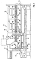
- the Indian FIG. 1 schematically illustrated first inventive sterilization tunnel 10 consists essentially of an inlet zone 11, a heating zone 12 and two cooling zones 13, 14.
- Pharmaceutical containers 1 such as ampoules, vials, vials or the like, coming from a cleaning machine, not shown, are in the inlet zone 11 of the Supplied sterilizing tunnel 10 and leave it at its opposite end 15 to the cooling zone 14 to be further processed in subsequent filling and sealing machines, not shown.
- the conveyor belt 17 is formed as an air-permeable wire mesh belt made of stainless steel.
- Filter elements 18, 19 and 20 are arranged above the conveyor belt 17 10 large-area in the various zones of the sterilization tunnel Filter elements 18, 19 and 20 are arranged.
- the filter elements 18, 19 and 20 cooperate with fan means 22, 23 and 24, which are associated with the respective zone, and serve the circulation of the air in a respective closed circuit.
- the air flows generated by the blower devices 22, 23 and 24, which flow around the containers 1 during their transport through the sterilization tunnel 10 substantially from top to bottom as flow laminar flows (flow arrows 25), are tempered by means of heating or cooling devices (not shown) ,
- temperature sensors are arranged in the individual zones, which supply the measured temperatures of the control device of the sterilization tunnel 10 as an input variable.
- the control device then controls the heating or cooling devices accordingly, including arranged in the zones, not shown Zu poverty- and exhaust air valves are used, which also serve to compensate for leakage and fürströmlessnessen.
- Zu poverty- and exhaust air valves are used, which also serve to compensate for leakage and fürströmlessnessen.
- In order to reduce the said Kochströmlessnesse between the individual zones are additionally arranged between and within a zone height adjustable locks 26, 27 and 28, whose position is adapted to the respective Be Strukturnis love.
- the containers 1 from above, d. H. flow around from the container mouth 2 ago in the direction of the container bottom 3, a non-uniform temperature distribution over the container height.
- the sterilization tunnel 10 is particularly well-trained.
- the heating zone 12 is divided into two areas 33 and 34 by means of a partition wall 31, whose side facing the conveyor belt 17 is designed as a height-adjustable intermediate wall 32. While in the one area 33, the blower device 22 provides a heated air flow, in the other area 34, which is arranged on the inlet zone 11 side facing, a plurality of radiant heat generating heaters 35, 36, 37 are arranged.
- the heating devices 35, 36, 37 which are embodied in particular in the form of an infrared radiator, are below the radiation-permeable conveyor belt 17 near the container bottoms 3, above the conveyor belt 17 near the container mouths 2 and, if appropriate, laterally of the conveyor belt 17 at the level of the container Container mouths 2 arranged outside of rigid or running side guides 38 for the conveyor belt 17, wherein the heaters 35, 36 in the embodiment transversely, and the heaters 37 extend along the conveying direction of the containers 1 through the sterilization tunnel 10. Furthermore, at least one temperature sensor 39, which is coupled to the control device of the sterilization tunnel 10, is arranged in the region 34.
- the heating devices 35, 36, 37 allow, depending on the application, a targeted stronger preheating of certain container areas, for example the container bottoms 3, in order to avoid thermal stresses in the containers 1 during the subsequent further heating in the area 33 by means of the air flow.
- the container floors 3 facing heaters 35 are set to a higher temperature than the other heaters 36, 37th
- an emulsion-like substance eg silicone
- the radiant heat of the heating devices 35 , 36, 37 also be very aggressive, d. h. That within a very short time by means of the heaters 35, 36, 37 a required for the coating of the containers 1 temperature is reached in the containers 1, which is subsequently possibly even reduced in the region 33 again.
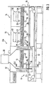
- second sterilization tunnel 10a are in contrast to the sterilization tunnel 10 in the heating zone 12 only additional heaters 35 below the radiation-permeable conveyor belt 17, and heaters 37 laterally and outside the side guides 38 analogous to the sterilization tunnel 10, but no radiant heat generating heaters above the containers 1. Rather, the containers 1 are heated in the entire Edelone 12 by means of the fan 22 with hot air from above, which also means that in the sterilizing tunnel 10 a no partition 31 is provided according to the sterilization tunnel 10, which divides the heating zone 12 into different areas.
- radiant heat generating heaters 40, 41 are arranged in the sterilizing tunnel 10a in the first cooling zone 13.
- These heaters 40, 41 which are also rod-shaped, are arranged above the container mouths 2 on the side facing the heating zone 12, and laterally and outside the side guides 38 at the level of the container mouths 2, and are arranged in the cooling zone 13 near the heaters 40 arranged, not shown, temperature sensor, which is coupled to the control device of the sterilization tunnel 10, driven.
- the heating devices 40, 41 it is possible, the transferred from the heating zone 12 containers 1, which have a relatively high temperature, Cool somewhat less quickly in the area of their container mouths 2, so that overall a more uniform cooling of the containers 1 is made possible.
- additional heating devices 35, 37, 40, 41 realized in the sterilization tunnel 10a, a material-friendly heating and cooling of the containers 1 to avoid thermal stresses and heat cracks in the containers 1 can thus be achieved.
- the sterilizing tunnel 10 according to the invention can be varied in many ways without deviating from the essence of the invention, which is to arrange additional radiant heat generating heaters in the sterilizing tunnel 10, which in cooperation with the air flows generated by the blower means for uniform heating or ensure a uniform cooling of the containers 1. So it is conceivable, for example, to dispense with the upper and side heaters 36, 37. Furthermore, the sterilization tunnel 10 can additionally have the heating devices 40, 41 located in the cooling zone 13 of the sterilization tunnel 10 a in order to treat the containers 1 with particular care in respect of the thermal stresses.
Description
Die Erfindung betrifft einen Sterilisiertunnel für pharmazeutische Behältnisse nach dem Oberbegriff des Anspruchs 1, wie er aus der
Weiterhin ist es bekannt, die Behältnisse vor dem Eintritt in den Sterilisiertunnel mit emulsionsartigen Substanzen (z. B. Silikon) zu beschichten. In diesem Fall dient der Sterilisiertunnel zusätzlich auch zum Fixieren und Einbrennen der Substanz in der Behältnisoberfläche. Bei den bisher verwendeten Sterilisiertunneln mit durch Filter umgewälzter Heißluft kann es dabei zum Zusetzen der Filter durch Abbrandrückstände der Substanzen und somit zu einer Reduzierung der Lebensdauer der Filter kommen.Furthermore, it is known to coat the containers with emulsion-type substances (eg silicone) before they enter the sterilization tunnel. In this case, the sterilization tunnel also serves to fix and burn the substance in the container surface. In the previously used sterilization tunnels with hot air circulated through filters, it is possible for the filters to become clogged by burnt-off residues of the substances and thus to a reduction in the service life of the filters.
Weiterhin sind Sterilisiertunnel bekannt, deren Heizeinrichtungen alleine mittels Strahlungswärmeerzeugern (z.B. Infrarot-Strahler) betrieben werden.Furthermore, sterilizing tunnels are known whose heating devices are operated solely by means of radiant heat generators (for example infrared radiators).
Der erfindungsgemäße Sterilisiertunnel für pharmazeutische Behältnisse mit den Merkmalen des Anspruchs 1 hat demgegenüber den Vorteil, dass die Behältnisse thermisch besonders schonend behandelt werden, so dass die Wahrscheinlichkeit von Spannungsrissen reduziert wird.The sterilization tunnel according to the invention for pharmaceutical containers with the features of
Weitere vorteilhafte Weiterbildungen des erfindungsgemäßen Sterilisiertunnels für pharmazeutische Behältnisse sind in den Unteransprüchen angegeben.Further advantageous developments of the sterilization tunnel according to the invention for pharmaceutical containers are specified in the subclaims.
Um das Einwirken der Strahlungswärme auf die Behältnisböden zu verbessern ist es vorteilhaft, die Transporteinrichtung, auf der die Behältnisse gefördert werden, als strahlungsdurchlässiges Drahtgeflechtband auszubilden.In order to improve the effect of the radiant heat on the container bottoms, it is advantageous to form the transport device on which the containers are conveyed as a radiation-permeable wire mesh belt.
Soll der Sterilisiertunnel auch zum Beschichten und Einbrennen von emulsionsartigen Substanzen verwendet werden, so ist es vorgesehen, in der Heizzone zusätzliche Strahlungewärme erzeugende Heizeinrichtungen zu verwenden, die oberhalb bzw. seitlich der Behältnisse angeordnet sind. Dadurch ist der Beschichtungs- und Einbrennprozeß beim nachfolgenden Umspülen der Behältnisse mit Heißluft bereits zumindest weitgehend abgeschlossen ist, so daß der Anteil von Abbrandrückständen in der durch die Filter umgewälzten Luft reduziert ist.If the sterilization tunnel is also to be used for coating and baking emulsion-like substances, it is provided to use additional radiation-heat generating heating devices in the heating zone, which are arranged above or to the side of the containers. As a result, the coating and baking process during subsequent rinsing of the containers with hot air is already at least largely completed, so that the proportion of Abbrandrückständen is reduced in the air circulated through the filter.
Um die Empfindlichkeit der Behältnisse gegen Spannungsrisse zu reduzieren ist es weiterhin vorteilhaft, in der Kühlzone zumindest oberhalb der Behältnismündungen ebenfalls Strahlungswärme erzeugende Heizeinrichtungen vorzusehen.In order to reduce the sensitivity of the containers to stress cracks, it is also advantageous to provide heating means which also generate radiant heat in the cooling zone, at least above the container mouths.
Zwei Ausführungsbeispiele der Erfindung sind in der Zeichnung dargestellt und wedren nachfolgend näher erläutert. Die
-
Figur 1 -
Figur 2Figur 1 -
Figur 3 -
Figur 4 einen Teilschnitt in der Ebene IV-IV derFigur 3
-
FIG. 1 a longitudinal section through a first sterilizing tunnel according to the invention in a simplified representation, -
FIG. 2 a partial section in the level II-II ofFIG. 1 during operation of the first sterilization tunnel, -
FIG. 3 a longitudinal section through a second sterilization tunnel in a simplified representation and -
FIG. 4 a partial section in the level IV-IV ofFIG. 3 during operation of the second sterilization tunnel.
Der in der
Zum Transport der Behältnisse 1 durch die einzelnen Zonen innerhalb des Sterilisiertunnels 10 dient ein horizontal vorzugsweise kontinuierlich angetriebenes, endloses Transportband 17. Vorzugsweise ist das Transportband 17 als luftdurchlässiges Drahtgeflechtband aus Edelstahl ausgebildet.For transporting the
Oberhalb des Transportbandes 17 sind in den verschiedenen Zonen des Sterilisiertunnels 10 großflächige Filterelemente 18, 19 und 20 angeordnet. Die Filterelemente 18, 19 und 20 wirken mit Gebläseeinrichtungen 22, 23 und 24 zusammen, welche der jeweiligen Zone zugeordnet sind, und der Umwälzung der Luft in einem jeweils geschlossenen Kreislauf dienen. Die von den Gebläseeinrichtungen 22, 23 und 24 erzeugten Luftströmungen, welche die Behältnisse 1 während ihres Transports durch den Sterilisiertunnel 10 im Wesentlichen von oben nach unten als sogenannte Laminarflow-Strömungen umströmen (Strömungspfeile 25), werden mittels nicht dargestellter Heiz- bzw. Kühleinrichtungen temperiert. Dazu sind in den einzelnen Zonen Temperatursensoren angeordnet, welche die gemessenen Temperaturen der Steuereinrichtung des Sterilisiertunnels 10 als Eingangsgröße zuführen. Die Steuereinrichtung regelt dann die Heiz- bzw. Kühleinrichtungen entsprechend, wozu auch in den Zonen angeordnete, nicht dargestellte Zuluft- und Abluftklappen dienen, die darüber hinaus dem Ausgleich von Leck- und Überströmverlusten dienen. Um die genannten Überströmverluste zwischen den einzelnen Zonen zu verringern, sind zwischen und innerhalb einer Zone zusätzlich noch höhenverstellbare Schleusen 26, 27 und 28 angeordnet, deren Stellung der jeweiligen Behältnishöhe angepaßt ist.Above the
Aufgrund der von den Gebläseeinrichtungen 22, 23 und 24 erzeugten Luftströmungen, die die Behältnisse 1 von oben, d. h. von der Behältnismündung 2 her in Richtung des Behältnisbodens 3 umströmen, stellt sich eine ungleichmäßige Temperaturverteilung über die Behältnishöhe ein. So weisen die Behältnismündungen 2 beim Durchlauf durch die Heizzone 12 eine höhere Temperatur auf als die Behältnisböden 3. Dies rührt daher, dass die Heißluft in der Heizzone 12 zuerst mit der Behältnismündung 2 in Kontakt gerät.Due to the air currents generated by the
Um die Temperaturverteilung entlang der Höhe der Behältnisse 1 gezielt beeinflussen zu können, um somit Wärmespannungen zu vermeiden, die die Behältnisse 1 vorschädigen können, und darüber hinaus das Einbrennen von emulsionsartigen Partikeln in den Behältnisinnenwänden günstig zu beeinflussen, ist der Sterilisiertunnel 10 besonders ausgebildet. Hierzu ist die Heizone 12 mittels einer Trennwand 31, deren dem Transportband 17 zugewandte Seite als höhenverstellbare Zwischenwand 32 ausgebildet ist, in zwei Bereiche 33 und 34 unterteilt. Während in dem einen Bereich 33 die Gebläseeinrichtung 22 für einen erhitzten Luftstrom sorgt, sind in dem anderen Bereich 34, welcher auf der der Einlaufzone 11 zugewandten Seite angeordnet ist, mehrere Strahlungswärme erzeugende Heizeinrichtungen 35, 36, 37 angeordnet.In order to be able to influence the temperature distribution along the height of the
Die insbesondere als Infrarot-Strahler ausgebildeten Heizeinrichtungen 35, 36, 37, welche im Ausführungsbeispiel stabförmig dargestellt sind, sind unterhalb des strahlungsdurchlässigen Transportbandes 17 nahe der Behältnisböden 3, oberhalb des Transportbandes 17 nahe der Behältnismündungen 2, sowie gegebenenfalls seitlich des Transportbandes 17 in Höhe der Behältnismündungen 2 außerhalb von starren oder mitlaufenden Seitenführungen 38 für das Transportband 17 angeordnet, wobei sich die Heizeinrichtungen 35, 36 im Ausführungsbeispiel quer, und die Heizeinrichtungen 37 längs zur Förderrichtung der Behältnisse 1 durch den Sterilisiertunnel 10 erstrecken. Ferner ist in dem Bereich 34 noch wenigstens ein Temperaturfühler 39 angeordnet, welcher mit der Steuereinrichtung des Sterilisiertunnels 10 gekoppelt ist.The
Die Heizeinrichtungen 35, 36, 37 ermöglichen je nach Anwendungsfall eine gezielte stärkere Vorerwärmung bestimmter Behältnisbereiche, beispielsweise der Behältnisböden 3, um bei der nachfolgenden weiteren Erwärmung in dem Bereich 33 mittels der Luftströmung Wärmespannungen in den Behältnissen 1 zu vermeiden. In diesem Fall sind die den Behältnisböden 3 zugewandten Heizeinrichtungen 35 auf eine höhere Temperatur eingestellt, als die übrigen Heizeinrichtungen 36, 37.The
Soll dagegen beispielsweise eine emulsionsartige Substanz (z. B. Silikon), welche der Beschichtung der Behältnisse 1 dient, bereits im Bereich 34 eingebrannt sein, damit mögliche Abbrandrückstände nachfolgend das Filterelement 18 im Bereich 33 möglichst gering belasten, so kann die Strahlungswärme der Heizeinrichtungen 35, 36, 37 auch sehr aggressiv eingestellt sein, d. h., dass innerhalb kürzester Zeit mittels der Heizeinrichtungen 35, 36, 37 eine für die Beschichtung der Behältnisse 1 benötigte Temperatur in den Behältnissen 1 erreicht wird, welche nachfolgend in dem Bereich 33 gegebenenfalls sogar wieder vermindert wird.On the other hand, if, for example, an emulsion-like substance (eg silicone), which serves to coat the
Bei dem in den
Zusätzlich sind bei dem Sterilisiertunnel 10a in der ersten Kühlzone 13 weitere, ebenfalls Strahlungswärme erzeugende Heizeinrichtungen 40, 41 angeordnet. Diese Heizeinrichtungen 40, 41, welche ebenfalls stabförmig ausgebildet sind, sind oberhalb der Behältnismündungen 2 auf der der Heizzone 12 zugewandten Seite, sowie seitlich und außerhalb der Seitenführungen 38 in Höhe der Behältnismündungen 2 angeordnet, und werden über einen in der Kühlzone 13 nahe der Heizeinrichtungen 40 angeordneten, nicht dargestellten Temperaturfühler, der mir der Steuereinrichtung des Sterilisiertunnels 10 gekoppelt ist, angesteuert.In addition, in the sterilizing
Mit den Heizeinrichtungen 40, 41 ist es möglich, die aus der Heizzone 12 überführten Behältnisse 1, welche eine verhältnismäßig hohe Temperatur aufweisen, im Bereich ihrer Behältnismündungen 2 etwas weniger schnell abzukühlen, so dass insgesamt gesehen eine gleichmäßigere Abkühlung der Behältnisse 1 ermöglicht wird. Mit der im Sterilisiertunnel 10a verwirklichten Anordnung zusätzlicher Heizeinrichtungen 35, 37, 40, 41 läßt sich somit eine materialschonende Aufheizung und Abkühlung der Behältnisse 1 zur Vermeidung von Wärmespannungen und Wärmerissen in den Behältnissen 1 erzielen.With the
Der erfindungsgemäß Sterilisiertunnel 10 kann in vielfältiger Art und Weise abgeändert werden, ohne vom Kern der Erfindung abzuweichen, welcher darin besteht, zusätzliche, Strahlungswärme erzeugende Heizeinrichtungen im Sterilisiertunnel 10 anzuordnen, die im Zusammenwirken mit den von den Gebläseeinrichtungen erzeugten Luftströmungen für eine gleichmäßige Erwärmung bzw. eine gleichmäßige Abkühlung der Behältnisse 1 sorgen. So ist es beispielsweise denkbar, auf die oberen und seitlichen Heizeinrichtungen 36, 37 zu verzichten. Weiterhin kann der Sterilisiertunnel 10 zusätzlich die in der Kühlzone 13 des Sterilisiertunnels 10a befindlichen Heizeinrichtungen 40, 41 aufweisen, um die Behältnisse 1 bzgl. der Wärmespannungen besonders schonend zu behandeln.The sterilizing
Claims (7)
- Sterilizing tunnel (10; 10a) for pharmaceutical containers (1), with a transport device (17) conveying the containers (1) along a heating zone (12) and at least one cooling zone (13, 14) and with blower devices (22, 23, 24) for generating in the heating zone (12) and the at least one cooling zone (13, 14) air flows which wash around the containers (1), wherein at least in the region of the heating zone (12), in addition to the blower device (22), at least one heating device (35) is arranged which generates radiant heat and which acts on the container bottoms (3), characterized in that the at least one heating device (35) is arranged in the heating zone (12) in a first region (34) which is separated by means of a partition (31) from a second region (33) in which the blower device (22) acts on the containers (1).
- Sterilizing tunnel according to Claim 1, characterized in that the at least one heating device (35) is arranged on the side facing an entry zone (11) of the heating zone (12).
- Sterilizing tunnel according to Claim 1 or 2, characterized in that the transport device (17) is designed as a radiation-permeable wire-mesh band, and in that the at least one heating device (35) is arranged on that side of the transport device (17) which lies opposite the containers (1).
- Sterilizing tunnel according to Claim 1, characterized in that further heating devices (36, 37) generating radiant heat are arranged in the first region (34) above or at the side of the containers (1).
- Sterilizing tunnel according to one of Claims 1 to 4, characterized in that at least one additional heating device (40) generating radiant heat is arranged additionally in the region of the cooling zone (13, 14) on the side facing the heating zone (12).
- Sterilizing tunnel according to Claim 5, characterized in that the at least one additional heating device (40) is arranged above the containers (1).
- Sterilizing tunnel according to one of Claims 1 to 6, characterized in that a temperature sensor (39), which cooperates with the control device of the sterilizing tunnel (10), is arranged in the region of the at least heating device (35).
Applications Claiming Priority (3)
| Application Number | Priority Date | Filing Date | Title |
|---|---|---|---|
| DE10158571A DE10158571A1 (en) | 2001-11-29 | 2001-11-29 | Sterilization tunnel for pharmaceutical containers |
| DE10158571 | 2001-11-29 | ||
| PCT/DE2002/002793 WO2003047637A1 (en) | 2001-11-29 | 2002-07-30 | Sterilizing tunnel for pharmaceutical containers |
Publications (3)
| Publication Number | Publication Date |
|---|---|
| EP1450867A1 EP1450867A1 (en) | 2004-09-01 |
| EP1450867B1 EP1450867B1 (en) | 2008-02-27 |
| EP1450867B2 true EP1450867B2 (en) | 2013-09-11 |
Family
ID=7707376
Family Applications (1)
| Application Number | Title | Priority Date | Filing Date |
|---|---|---|---|
| EP02764535.7A Expired - Lifetime EP1450867B2 (en) | 2001-11-29 | 2002-07-30 | Sterilizing tunnel for pharmaceutical containers |
Country Status (5)
| Country | Link |
|---|---|
| US (2) | US20040105798A1 (en) |
| EP (1) | EP1450867B2 (en) |
| JP (1) | JP4388815B2 (en) |
| DE (2) | DE10158571A1 (en) |
| WO (1) | WO2003047637A1 (en) |
Families Citing this family (19)
| Publication number | Priority date | Publication date | Assignee | Title |
|---|---|---|---|---|
| DE10158571A1 (en) | 2001-11-29 | 2003-06-12 | Bosch Gmbh Robert | Sterilization tunnel for pharmaceutical containers |
| ITBO20050011A1 (en) * | 2005-01-12 | 2006-07-13 | Ima Spa | UNIT FOR STERILIZATION AND DEPIROGENATION OF CONTAINERS |
| DE102007050999B4 (en) | 2007-10-25 | 2017-02-23 | Robert Bosch Gmbh | Sterilization tunnel for pharmaceutical containers |
| RU2528699C2 (en) * | 2009-07-03 | 2014-09-20 | Тетра Лаваль Холдингз Энд Файнэнс С.А. | Device and method of package sterilisation |
| US10350139B2 (en) * | 2011-10-25 | 2019-07-16 | Corning Incorporated | Pharmaceutical glass packaging assuring pharmaceutical sterility |
| DE102013204668A1 (en) * | 2012-04-05 | 2013-10-10 | Robert Bosch Gmbh | Method and device for cooling previously sterilized pharmaceutical containers |
| US9901651B2 (en) | 2012-11-01 | 2018-02-27 | Kpr U.S., Llc | System and method for treatment of a surface of an injection device |
| CN103212104A (en) * | 2013-03-29 | 2013-07-24 | 施佳卫 | Gas sterilizing device |
| CN103170000A (en) * | 2013-03-29 | 2013-06-26 | 施佳卫 | Gas filter sterilization device |
| CN103169991A (en) * | 2013-03-29 | 2013-06-26 | 张玉方 | High-temperature sterilization device |
| ITPR20130031A1 (en) | 2013-04-05 | 2014-10-06 | One Love Di Tarasconi Ermina & C S A S | STERILIZATION PLANT |
| ITUD20130064A1 (en) | 2013-05-13 | 2014-11-14 | Steelco Spa | TUNNEL MACHINE FOR WASHING OBJECTS |
| MX2016002928A (en) | 2013-09-09 | 2016-06-06 | Covidien Lp | Single-use device for injection of cartridge drugs. |
| DE102014200145A1 (en) * | 2014-01-08 | 2015-07-09 | Robert Bosch Gmbh | Transport device for transporting containers with improved side guidance |
| US10588786B2 (en) * | 2016-05-19 | 2020-03-17 | The Procter & Gamble Company | Method and apparatus for microwave product treatment |
| JP6533775B2 (en) * | 2016-12-26 | 2019-06-19 | チヨダエレクトリック株式会社 | Dry heat sterilizer |
| JP7374899B2 (en) | 2017-12-11 | 2023-11-07 | グラクソスミスクライン、インテレクチュアル、プロパティー、ディベロップメント、リミテッド | Modular aseptic production system |
| US10864291B2 (en) * | 2017-12-26 | 2020-12-15 | Asp Global Manufacturing Gmbh | Process and apparatus for cleaning, disinfection, sterilization, or combinations thereof |
| DE102020114221A1 (en) * | 2020-05-27 | 2021-12-02 | Syntegon Technology Gmbh | Apparatus and method for sudden sterilization |
Family Cites Families (13)
| Publication number | Priority date | Publication date | Assignee | Title |
|---|---|---|---|---|
| DE1248234B (en) | 1959-08-31 | 1967-08-24 | Chirana Praha N P | Automatic hot air sterilizer |
| DE3321195A1 (en) * | 1983-06-11 | 1984-12-13 | Bayer Ag, 5090 Leverkusen | Device for the dry heat sterilisation of glass vessels for medicaments for parenteral use |
| DE3506788A1 (en) | 1985-02-22 | 1985-07-18 | Detlef 1000 Berlin Güttschow | Method of continuously measuring and controlling the temperature course of containers and accessories for parenteral drugs |
| DE3510286A1 (en) | 1985-03-19 | 1986-09-25 | Hans Gilowy Maschinenfabrik "Meteorwerk" GmbH & Co, 1000 Berlin | Method of operating radiation sterilisation apparatus and a device for carrying out the method |
| US4727800A (en) * | 1985-05-28 | 1988-03-01 | Anheuser-Busch, Incorporated | Pasteurization apparatus |
| DE3734830A1 (en) * | 1987-10-14 | 1989-04-27 | Gilowy Hans Maschf | METHOD FOR STERILIZING TEMPERATURE-RESERVABLE CONTAINERS UNDER CLEAN ROOM CONDITIONS |
| DE8913860U1 (en) * | 1989-11-24 | 1991-03-21 | Robert Bosch Gmbh, 7000 Stuttgart, De | |
| US5022165A (en) * | 1990-06-29 | 1991-06-11 | The West Company, Incorporated | Sterilization tunnel |
| DE4131258A1 (en) | 1991-09-17 | 1992-05-07 | Siedler Torsten | Sterilisation appts. for medical flasks - with controlled cooling section air circulation to heating section |
| DE19804386C2 (en) * | 1998-02-04 | 1999-12-30 | Ttp Ingenieurbuero | Method and device for drying or heat treating products, in particular with the aid of microwave radiation, and banana chips and banana powder produced therewith |
| IT1299674B1 (en) * | 1998-05-29 | 2000-03-24 | Sasib Beverage S P A Ora Sasib | CONTROL SYSTEM OF THE PASTEURIZATION HEAT TREATMENT, IN PARTICULAR OF PACKAGED FOOD PRODUCTS, IN PASTEURIZERS A |
| DE19846277C2 (en) * | 1998-10-08 | 2000-07-13 | Bosch Gmbh Robert | Sterilization tunnel |
| DE10158571A1 (en) | 2001-11-29 | 2003-06-12 | Bosch Gmbh Robert | Sterilization tunnel for pharmaceutical containers |
-
2001
- 2001-11-29 DE DE10158571A patent/DE10158571A1/en not_active Ceased
-
2002
- 2002-07-30 DE DE50211799T patent/DE50211799D1/en not_active Expired - Lifetime
- 2002-07-30 WO PCT/DE2002/002793 patent/WO2003047637A1/en active IP Right Grant
- 2002-07-30 EP EP02764535.7A patent/EP1450867B2/en not_active Expired - Lifetime
- 2002-07-30 JP JP2003548892A patent/JP4388815B2/en not_active Expired - Fee Related
- 2002-07-30 US US10/470,343 patent/US20040105798A1/en not_active Abandoned
-
2008
- 2008-01-11 US US12/007,499 patent/US8501110B2/en not_active Expired - Fee Related
Also Published As
| Publication number | Publication date |
|---|---|
| WO2003047637A1 (en) | 2003-06-12 |
| JP2005511145A (en) | 2005-04-28 |
| US20080181826A1 (en) | 2008-07-31 |
| EP1450867A1 (en) | 2004-09-01 |
| EP1450867B1 (en) | 2008-02-27 |
| DE10158571A1 (en) | 2003-06-12 |
| JP4388815B2 (en) | 2009-12-24 |
| US20040105798A1 (en) | 2004-06-03 |
| US8501110B2 (en) | 2013-08-06 |
| DE50211799D1 (en) | 2008-04-10 |
Similar Documents
| Publication | Publication Date | Title |
|---|---|---|
| EP1450867B2 (en) | Sterilizing tunnel for pharmaceutical containers | |
| EP1763428A1 (en) | Heating furnace for preforms | |
| EP2676092B1 (en) | Device for controllling the temperature of vehicle bodies | |
| DE19708580A1 (en) | Treatment device for treating products using a gaseous treatment medium with a conveyor and method for operating the same | |
| EP0891526A1 (en) | Device for heat-treating bulk materials in feed screws and bulk material drying method | |
| WO2019115140A1 (en) | Apparatus for supplying protective gas, heating and supplying powder, device and method for the additive manufacturing of components, and component | |
| DE102017121224A1 (en) | Apparatus and method for thermal or thermo-chemical treatment of material | |
| EP0963319B1 (en) | Method for controlling air speed in a sterilizing tunnel during the heating of same tunnel | |
| EP1352571B1 (en) | Process and apparatus for microwave heating of readymade meals sealed in trays | |
| EP3755506B1 (en) | Plant for producing a foodstuff | |
| DE102009054806A1 (en) | Drying of a food product | |
| DE60037935T2 (en) | CONTINUOUS TREATMENT SYSTEM | |
| CH629256A5 (en) | DEVICE FOR COOLING LONG-STRETCHED WARM WORKPIECES. | |
| DE10330196B4 (en) | Plant for the heat treatment of glass | |
| DE102004028236B3 (en) | Assembly for heating workpieces before shaping in a press, e.g. high tensile steel sheets for automobile bodywork components, has a kiln with a jet field and fans to give the workpieces a convective heating action | |
| DE2659516A1 (en) | DEVICE FOR PROMOTING OBJECTS | |
| DE202010002798U1 (en) | drying device | |
| DE19539856C2 (en) | Steam oven for baked goods | |
| DE2112375B2 (en) | Device for sterilizing objects | |
| EP0512244A1 (en) | Apparatus for sterilising packaging containers, subjected to high temperatures | |
| DE19517824B4 (en) | Method and device for cooking meat and sausage products with steam | |
| DE69931781T2 (en) | Device for heat treatment of a food product | |
| DE3204690C2 (en) | Drying device for powdery or granular pharmaceutical goods | |
| DE1471957C (en) | Method and device for treating panes of glass | |
| DE19920136A1 (en) | kiln |
Legal Events
| Date | Code | Title | Description |
|---|---|---|---|
| PUAI | Public reference made under article 153(3) epc to a published international application that has entered the european phase |
Free format text: ORIGINAL CODE: 0009012 |
|
| 17P | Request for examination filed |
Effective date: 20040629 |
|
| AK | Designated contracting states |
Kind code of ref document: A1 Designated state(s): AT BE BG CH CY CZ DE DK EE ES FI FR GB GR IE IT LI LU MC NL PT SE SK TR |
|
| GRAP | Despatch of communication of intention to grant a patent |
Free format text: ORIGINAL CODE: EPIDOSNIGR1 |
|
| GRAS | Grant fee paid |
Free format text: ORIGINAL CODE: EPIDOSNIGR3 |
|
| GRAA | (expected) grant |
Free format text: ORIGINAL CODE: 0009210 |
|
| AK | Designated contracting states |
Kind code of ref document: B1 Designated state(s): CH DE FR IT LI |
|
| RBV | Designated contracting states (corrected) |
Designated state(s): CH DE FR IT LI |
|
| REG | Reference to a national code |
Ref country code: CH Ref legal event code: NV Representative=s name: SCINTILLA AG, DIREKTION Ref country code: CH Ref legal event code: EP |
|
| REF | Corresponds to: |
Ref document number: 50211799 Country of ref document: DE Date of ref document: 20080410 Kind code of ref document: P |
|
| PLBI | Opposition filed |
Free format text: ORIGINAL CODE: 0009260 |
|
| EN | Fr: translation not filed | ||
| 26 | Opposition filed |
Opponent name: BAUSCH + STROEBEL MASCHINENFABRIK ILSHOFEN GMBH + Effective date: 20081126 |
|
| PLAX | Notice of opposition and request to file observation + time limit sent |
Free format text: ORIGINAL CODE: EPIDOSNOBS2 |
|
| PG25 | Lapsed in a contracting state [announced via postgrant information from national office to epo] |
Ref country code: FR Free format text: LAPSE BECAUSE OF FAILURE TO SUBMIT A TRANSLATION OF THE DESCRIPTION OR TO PAY THE FEE WITHIN THE PRESCRIBED TIME-LIMIT Effective date: 20081219 |
|
| PLBB | Reply of patent proprietor to notice(s) of opposition received |
Free format text: ORIGINAL CODE: EPIDOSNOBS3 |
|
| PGFP | Annual fee paid to national office [announced via postgrant information from national office to epo] |
Ref country code: CH Payment date: 20110725 Year of fee payment: 10 |
|
| RIC2 | Information provided on ipc code assigned after grant |
Ipc: A61L 2/08 20060101ALI20121120BHEP Ipc: B65B 55/02 20060101ALI20121120BHEP Ipc: A61L 2/04 20060101AFI20121120BHEP Ipc: B65B 55/08 20060101ALI20121120BHEP |
|
| REG | Reference to a national code |
Ref country code: CH Ref legal event code: PL |
|
| PG25 | Lapsed in a contracting state [announced via postgrant information from national office to epo] |
Ref country code: CH Free format text: LAPSE BECAUSE OF NON-PAYMENT OF DUE FEES Effective date: 20120731 Ref country code: LI Free format text: LAPSE BECAUSE OF NON-PAYMENT OF DUE FEES Effective date: 20120731 |
|
| PUAH | Patent maintained in amended form |
Free format text: ORIGINAL CODE: 0009272 |
|
| STAA | Information on the status of an ep patent application or granted ep patent |
Free format text: STATUS: PATENT MAINTAINED AS AMENDED |
|
| 27A | Patent maintained in amended form |
Effective date: 20130911 |
|
| AK | Designated contracting states |
Kind code of ref document: B2 Designated state(s): CH DE FR IT LI |
|
| REG | Reference to a national code |
Ref country code: DE Ref legal event code: R102 Ref document number: 50211799 Country of ref document: DE Effective date: 20130911 |
|
| REG | Reference to a national code |
Ref country code: DE Ref legal event code: R082 Ref document number: 50211799 Country of ref document: DE Representative=s name: DREISS PATENTANWAELTE PARTG MBB, DE Ref country code: DE Ref legal event code: R081 Ref document number: 50211799 Country of ref document: DE Owner name: SYNTEGON TECHNOLOGY GMBH, DE Free format text: FORMER OWNER: ROBERT BOSCH GMBH, 70469 STUTTGART, DE Ref country code: DE Ref legal event code: R081 Ref document number: 50211799 Country of ref document: DE Owner name: SYNTEGON TECHNOLOGY GMBH, DE Free format text: FORMER OWNER: ROBERT BOSCH PACKAGING TECHNOLOGY GMBH, 71332 WAIBLINGEN, DE |
|
| PGFP | Annual fee paid to national office [announced via postgrant information from national office to epo] |
Ref country code: IT Payment date: 20200731 Year of fee payment: 19 |
|
| PGFP | Annual fee paid to national office [announced via postgrant information from national office to epo] |
Ref country code: DE Payment date: 20210721 Year of fee payment: 20 |
|
| PG25 | Lapsed in a contracting state [announced via postgrant information from national office to epo] |
Ref country code: IT Free format text: LAPSE BECAUSE OF NON-PAYMENT OF DUE FEES Effective date: 20210730 |
|
| REG | Reference to a national code |
Ref country code: DE Ref legal event code: R071 Ref document number: 50211799 Country of ref document: DE |