EP1450157A2 - Machine and process for carrying out quick tests on textile materials for accessing colour fastness and-or ability to be dyed thereof - Google Patents
Machine and process for carrying out quick tests on textile materials for accessing colour fastness and-or ability to be dyed thereof Download PDFInfo
- Publication number
- EP1450157A2 EP1450157A2 EP04425072A EP04425072A EP1450157A2 EP 1450157 A2 EP1450157 A2 EP 1450157A2 EP 04425072 A EP04425072 A EP 04425072A EP 04425072 A EP04425072 A EP 04425072A EP 1450157 A2 EP1450157 A2 EP 1450157A2
- Authority
- EP
- European Patent Office
- Prior art keywords
- machine according
- witness
- sample
- multifibre
- holes
- Prior art date
- Legal status (The legal status is an assumption and is not a legal conclusion. Google has not performed a legal analysis and makes no representation as to the accuracy of the status listed.)
- Granted
Links
Images





Classifications
-
- D—TEXTILES; PAPER
- D06—TREATMENT OF TEXTILES OR THE LIKE; LAUNDERING; FLEXIBLE MATERIALS NOT OTHERWISE PROVIDED FOR
- D06B—TREATING TEXTILE MATERIALS USING LIQUIDS, GASES OR VAPOURS
- D06B23/00—Component parts, details, or accessories of apparatus or machines, specially adapted for the treating of textile materials, not restricted to a particular kind of apparatus, provided for in groups D06B1/00 - D06B21/00
- D06B23/10—Devices for dyeing samples
-
- G—PHYSICS
- G01—MEASURING; TESTING
- G01N—INVESTIGATING OR ANALYSING MATERIALS BY DETERMINING THEIR CHEMICAL OR PHYSICAL PROPERTIES
- G01N33/00—Investigating or analysing materials by specific methods not covered by groups G01N1/00 - G01N31/00
- G01N33/36—Textiles
Definitions
- the present invention refers to a machine and a process for carrying out quick tests on textile materials for accessing their colour fastness and/or ability to be dyed.
- a process for dyeing textile materials is known to usually include a step of checking the colour fastness thereof. Such inspection should be performed before unloading the materials from the machines in which the dyeing is carried out, in order to subject the materials, in case of unfavourable outcome, to a washing or cleaning treatment. During this step, in fact, it may be economically more advantageous to reprocess the materials than unloading them and classifying or selling them as second-rate or defective products.
- the main object of the present invention is to propose a machine and a process which allow carrying out tests or checks over colour fastness with maximum rapidity and reliability.
- This invention makes it possible to perform tests of colour fastness on dyed textiles, as well as tests for accessing their ability to be dyed, with maximum rapidity and extreme accuracy. Moreover, a machine according to the invention is easy to make, cost-effective and reliable even after a prolonged service life.
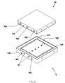
- a machine according to the invention comprises a stationary plate (1) and above this a movable plate (2) associated with a vertical actuator (3) to allow the movement thereof from and to the stationary plate (1), as indicated by the double arrow (F) in Fig. 1.
- the said plate (1) and actuator (3) are positioned in a fixed support structure which is not shown in the figures of the attached drawings for the sake of simplicity.
- Both the lower (1) and upper (2) plates are able to be heated. Illustrated in Fig. 1 are seats (10, 11) for corresponding electric resistances and temperature sensors which are connectable to a programmable source of electric power to heat both plates, that is, to bring them at predetermined temperatures over time intervals to be preset as well.
- the said plate (1) is provided with a plurality of through holes (12) which cross it from one side to the other, that is, from the upper to the lower faces thereof.
- the said holes (12) are aligned along a central line (t-t) of plate (1) and are equidistant from each other.
- the centre distance (d) between said holes (12) corresponds to the centre distance (e) between the strips of a multifibre witness (4), that is, of a ribbon-shaped fabric of known and preset width (according to specifications commonly enforced in this industrial sector, the whole witness length is about 9 cm) composed of more strips (40-45) of equal width and consisting of bundles of threads of different nature.
- the number of said holes (12) is equal to that of the strips (40-45) of the multifibre witness (4).
- the strips are made up of yarns of different nature, such as natural, artificial or synthetic fibres.
- the strip (40) may consist of wool threads, the strip (41) of cotton threads, the strip (42) of rayon viscosa threads, the strip (43) of polyamide threads, the strip (44) of polyester threads and the strip (45) of polyacrylonitrile.
- the multifibre witness (4) results formed by fibres of different materials - representing those most commonly used for the production of textiles - and orderly collected into strips adiacent to each other.
- the lower plate (1) Through said foles (12) of the lower plate (1) it is possible to inject liquid substances of different nature (such as water or organic solvents) by means of a relevant circuit (5).
- the latter comprises a plurality of liquid-holding vessels or tanks (50) individually connected to a pump (51) via respective conduits intercepted by valves (52) which allow selecting each time one of the tanks of liquids among those available.
- the said lower plate (1) exhibits two rows of discharge holes (13) located on the two sides of the central holes (12).
- each row of discharge holes (13) is within a corresponding channel-like groove (14), and two septa (15) of reduced height develop between the said groove (14) by forming two corresponding liquid-retention barriers which have the central row of injection holes (12) therebetween.
- each hole of the central row lies in a channel-shaped groove (16) which also includes two corresponding discharge holes (13) so that, within one same groove (16) the injection hole (12) will result intermediate between two discharge holes (13).
- the said discharge holes (13) are associated with liquid-sucking means (6) which include a suction pump (61) connected to the holes (13) via corresponding conduits, and which provides for discharging the liquids into one or more vessels (60).
- the liquid-discharging conduits are intercepted downstream of the suction pump (61) by corresponding valves (62) to allow the selection of one or the other of vessels (60) into which the liquids are to be discharged.
- the said plates (1, 2) may be rectangular, square or any other suitable shape.
- the multifibre witness (4) is positioned upon the stationary plate (1) so that each strip (40-45) thereof will result in correspondence of a hole (12).
- a sample fo the material under test is positioned upon the multifibre witness, as illustrated in Figs. 3B and 4B, then a command is given for lowering the upper plate (2) and heating both plates at the preset temperature.
- the plate (2) is caused to press the sample under test and the multifibre witness upon the lower plate (1), the test being made under known conditions of temperature and pressure.
- the liquids withdrawn in preset amounts by means of the pump (51) and valves (52) from one or more vessels (50) are injected through the holes (12).
- the pump (61) is activated for sucking the liquids previously injected and discharging them into one of the vessels (60).
- the plate (2) is lifted up to allow the visual inspection of the multifibre witness (4) and, when required, of the sample.
- This inspection makes it possible to check the fastness of the sample's colour, that is, to check whether, and to which extent, one or more strips of the multifibre witness (4) result dyed, or in other words, whether the sample's colour results also on the fibres of one or more strips (40-45) under the test's temperature and pressure conditions.
- the liquids discharged into the vessels (60) can be subject to both visual and instrument-assisted examinations, such as the visual control of the colour and/or pH measurements.
- the present machine makes it possible to carry out the above described test while the materials are still in the dyeing station, so that, in case of unfavourable output, it is still possible to subject the materials to washing or cleaning, instead of unloading them and subjecting them to finishing treatments which make the washing and cleaning operations substantially ineffective.
- the adoption of a machine according to the present invention allows reducing drastically the amount of dyed textiles to be classified as defective or of second rate.
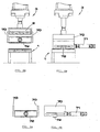
- a machine according to the invention, and as represented in the Figs. 6A-7B of the attached drawings, comprises a squeeze roller (7) able to roll over the sample under test and multifibre witness (4) located on the fixed plate (1) to exert a running or dynamic pressure of preset value thereon.
- the said roller (7) is engaged, freely rotating about its longitudinal axis, to two vertical plates (70) being fixed to said actuator (3), and is associated with a horizontal actuator (71) by which it is driven over the sample and multifibre witness (4) after being positioned thereon (see Fig. 6B).
- a machine according to the invention comprises, in place of said squeeze roller, a skid (72) able to slide over the sample under test and multifibre witness (4) located on the plate (1) to exert a dynamic pressure and a rubbing action over the whole surface of the sample or the multifibre witness.
- the actuations of the skid (72) are of the same type as those of the squeeze roller (7), as far as the both vertical and horizontal movements are concerned.
- a machine according to the invention may also be provided, in place of the said squeeze roller (7) or skid (72), with a disk able to rotatively slide over either the sample under test or the multifibre witness located on the fixed plate (1), to exert a rotary rubbing action onto the surface of the underlying material.
- the said disk (73) is associated with the vertical actuator (3) as previously described.
- the rotation of the disk (73) is determined by the actuator (71) which is engaged therewith via a rack (74) and pinion (75) transmission.
- the rack (74) is solid to the stem of the actuator. (71) ; the pinion (75) is solid to the disk (73) on the side opposite to that intended for the contact of the materials to be tested.
- a process according to the invention icludes, subsequent to a step for the positioning of a multifibre witness (4) onto a support (1) and of a sample to be tested onto said witness, a step for the injection of one or more liquids (for example, water or organic solvents) through said support (1), prefereably in such a manner that each strip of the multifibre witness (4) will be acted upon by them.
- the number of said holes (12) can however be different from that of strips (40-45) of the multifibre witness (4), the number of holes (12) being possibly lesser or higher than that of strips (40-45).
- the number of holes (12) formed on the plate (1) is more than one.
- such number coincides with that of strips (40-45) of the multifibre witness (4).
- the same machine may also be used to perform tests on textile materials for accessing their ability to be dyed.
- the multifibre witness is not used: a sample of raw textile (not dyed) is positioned on the plate (1) and subject to compression as described above, while the liquids sucked through the discharge holes (13) of plate (1) exit from the same holes and, through the discharge circuit (6), collect into the vessels (60). These liquids can then be subjected to analysis (of a type well known to those skilled in the art) to check for substances of a nature which could endanger their ability of dyeing the material under test.
Landscapes
- Engineering & Computer Science (AREA)
- Textile Engineering (AREA)
- Health & Medical Sciences (AREA)
- Life Sciences & Earth Sciences (AREA)
- Chemical & Material Sciences (AREA)
- Food Science & Technology (AREA)
- Medicinal Chemistry (AREA)
- Physics & Mathematics (AREA)
- Analytical Chemistry (AREA)
- Biochemistry (AREA)
- General Health & Medical Sciences (AREA)
- General Physics & Mathematics (AREA)
- Immunology (AREA)
- Pathology (AREA)
- Treatment Of Fiber Materials (AREA)
- Spectrometry And Color Measurement (AREA)
- Control Of Electric Motors In General (AREA)
- Investigating Strength Of Materials By Application Of Mechanical Stress (AREA)
Abstract
Description
- Fig. 1 shows a schematic diagram of a plant including a machine according to the invention;
- Fig. 2 is a schematic perspective view of the upper and lower plates;
- Fig. 3A is a plan view of the lower plate;
- Fig. 3B shows the same plate as Fig. 3A with a witness or fabric standard disposed thereon for carrying out a test;
- Fig. 4A is a plan view of an alternative embodiment of the lower plate according to the invention;
- Fig. 4B shows the same plate as Fig. 4A with a witness disposed thereon for carrying out a test;
- Fig. 5 is a plan view of a witness;
- Fig. 6A is a front view of a further embodiment of the machine according to the invention;
- Fig. 6B is a side view of the machine of Fig. 6A;
- Fig. 7A shows an enlarged detail of the drawing of Fig. 6A;
- Fig. 7B shows an enlarged detail of the drawing of Fig. 6B;
- Fig. 8A is a front view of a further embodiment of the machine according to the invention;
- Fig. 8B is a side view of the machine of Fig. 8A;
- Fig. 9A shows an enlarged detail of the drawing of Fig. 8A;
- Fig. 9B shows an enlarged detail of the drawing of Fig. 8B;
- Fig. 10A is a front view of a further embodiment of the machine according to the invention;
- Fig. 10B is a side view of the machine of Fig. 10A;
- Fig. 11A shows an enlarged detail of the drawing of
Fig. 10A;
Fig. 11B shows an enlarged detail of the drawing of Fig. 10B; - Fig. 11C shows the detail of Fig. 11 in plan view.
In the example, the centre distance (d) between said holes (12) corresponds to the centre distance (e) between the strips of a multifibre witness (4), that is, of a ribbon-shaped fabric of known and preset width (according to specifications commonly enforced in this industrial sector, the whole witness length is about 9 cm) composed of more strips (40-45) of equal width and consisting of bundles of threads of different nature. In other words, as shown by the example of the drawings, the number of said holes (12) is equal to that of the strips (40-45) of the multifibre witness (4). The strips are made up of yarns of different nature, such as natural, artificial or synthetic fibres. For example, the strip (40) may consist of wool threads, the strip (41) of cotton threads, the strip (42) of rayon viscosa threads, the strip (43) of polyamide threads, the strip (44) of polyester threads and the strip (45) of polyacrylonitrile.
In addition, the said lower plate (1) exhibits two rows of discharge holes (13) located on the two sides of the central holes (12).
The liquids injecting and sucking means are not shown in Figs. 6A, 6B, 8A, 8B, 10A and 10B for the sake of simplicity.
The number of said holes (12) can however be different from that of strips (40-45) of the multifibre witness (4), the number of holes (12) being possibly lesser or higher than that of strips (40-45). In any case, the number of holes (12) formed on the plate (1) is more than one.
Preferably, as in the example shown in the drawings, such number coincides with that of strips (40-45) of the multifibre witness (4).
Claims (16)
- Machine for carrying out quick tests of colour fastness on textile materials, comprising a plate (1) on which a sample of the material under test is to be located, and means (2; 7; 72) to compress the said sample and multifibre witness or fabric standard (4) on said plate (1), characterized in that the said plate (1) comprises a plurality of through holes (12) associated with means (5) for injecting one or more liquids therethrough.
- Machine according to claim 1 characterized in that the said holes (12) are lined up along a central line (t-t) of said plate (1) and are equidistant to each other.
- Machine according to one or more preceding claims characterized in that the distance (d) between said holes (12) corresponds to the centre distance between the strips (40-45) of a multifibre witness or fabric standard to be used in association with the sample of material under test.
- Machine according to one or more preceding claims characterized in that the said plate (1) exhibits a plurality of holes (13) for discharging liquids located laterally to said injection holes (12).
- Machine according to one or more preceding claims characterized in that the said discharge holes (13) are lined up along two separate rows.
- Machine according to one or more preceding claims characterized in that each injection hole (12) is a channel-shaped groove (16) which also includes two corresponding lateral discharge holes (13).
- Machine according to claim 5 characterized in that each row of discharge holes (13) is in correspondence of a channel-shaped groove (14).
- Machine according to one or more preceding claims characterized in that the said means for compressing the said sample and multifibre witness (4) comprise a plate (2) associated with a vertical actuator (3).
- Machine according to one or more claims 1 to 7 characterized in that the said means for compressing the said sample and multifibre witness (4) comprise a roller (7) associated with a with a vertical actuator (3) and a horizontal actuator (71).
- Machine according to one or more claims 1 to 7 characterized in that the said means for compressing the said sample and multifibre witness (4) comprise a skid (72) associated with a vertical actuator (3) and a horizontal actuator (71).
- Machine according to one or more claims 1 to 7 characterized in that the said means for compressing the said sample and multifibre witness (4) comprise a rotary disk (73) associated with a vertical actuator (3) and a horizontal actuator (71).
- Machine according to one or more preceding claims characterized in that the said plates (1, 2) are of square or rectangular shape.
- Machine according to one or more preceding claims characterized in that the said plates (1, 2) are able to be heated and the operating temperature thereof can be controlled by relevant sensors.
- Process for carrying out quick tests of colour fastness on textile materials, comprising a step for positioning a sample of material to be tested onto a support (1), characterized in that it further includes a step for the injection of one or more liquids through said support (1), said injection being operated through a plurality of holes (12) of support (1).
- Process according to claim 14 characterized in that it includes the positioning of a multifibre witness (4) on said support (1) in association with the sample of material to be tested.
- Process according to claim 14 characterized in that all the strips of said multifibre witness (4) result interested by said injection of one or more liquids delivered through said support (1).
Applications Claiming Priority (2)
| Application Number | Priority Date | Filing Date | Title |
|---|---|---|---|
| IT000041A ITFI20030041A1 (en) | 2003-02-18 | 2003-02-18 | MACHINE AND PROCEDURE FOR PERFORMING QUICK SOLIDITY TESTS |
| ITFI20030041 | 2003-02-18 |
Publications (3)
| Publication Number | Publication Date |
|---|---|
| EP1450157A2 true EP1450157A2 (en) | 2004-08-25 |
| EP1450157A3 EP1450157A3 (en) | 2004-09-08 |
| EP1450157B1 EP1450157B1 (en) | 2010-09-15 |
Family
ID=32732600
Family Applications (1)
| Application Number | Title | Priority Date | Filing Date |
|---|---|---|---|
| EP04425072A Expired - Lifetime EP1450157B1 (en) | 2003-02-18 | 2004-02-06 | Machine and process for carrying out quick tests on textile materials for accessing colour fastness and-or ability to be dyed thereof |
Country Status (8)
| Country | Link |
|---|---|
| US (1) | US7146868B2 (en) |
| EP (1) | EP1450157B1 (en) |
| CN (1) | CN100504384C (en) |
| AT (1) | ATE481634T1 (en) |
| DE (1) | DE602004029112D1 (en) |
| ES (1) | ES2351213T3 (en) |
| IT (1) | ITFI20030041A1 (en) |
| TW (1) | TWI290970B (en) |
Cited By (2)
| Publication number | Priority date | Publication date | Assignee | Title |
|---|---|---|---|---|
| CH700637A1 (en) * | 2009-03-19 | 2010-09-30 | Empa Testmaterialien Ag | Checking means for comparing devices in which textile parts are treated. |
| CN101858904A (en) * | 2009-04-10 | 2010-10-13 | 上海天祥质量技术服务有限公司 | Test method of urine stain colour fastness |
Families Citing this family (8)
| Publication number | Priority date | Publication date | Assignee | Title |
|---|---|---|---|---|
| RU2312177C1 (en) * | 2006-05-24 | 2007-12-10 | Государственное научное учреждение "Всероссийский научно-исследовательский институт по переработке лубяных культур" Российской академии сельскохозяйственных наук | Method for evaluating quality of treated flax fibers |
| GB0904833D0 (en) * | 2009-03-20 | 2009-05-06 | Nixtex Ltd | Measurement of textile fabrics |
| IT1394980B1 (en) * | 2009-07-30 | 2012-08-07 | Tecnorama Srl | DEVICE FOR DETERMINATION OF DYES IN SOLUTION OR DISPERSION INTENDED FOR THE PREPARATION OF DYEING BATHS FOR TEXTILE MATERIALS. |
| CN104345138B (en) * | 2013-08-01 | 2017-09-01 | 江西出入境检验检疫局检验检疫综合技术中心 | A kind of portable PERSPIRATION COLOR FASTNESS instrument |
| SA114350425B1 (en) * | 2014-04-10 | 2015-07-07 | محمد ادريس مبارك الصبحي سعود | Tool for detecting fastness of colors on fabrics |
| CN104020104B (en) * | 2014-06-23 | 2016-02-24 | 中国烟草总公司郑州烟草研究院 | The colour fastness of resistance to saliva based on hot air circulating system temperature control tests the contact device that automatically bears a heavy burden |
| CN105866392B (en) * | 2016-06-02 | 2017-07-21 | 浙江多元纺织科技有限公司 | A kind of tent cloth fade resistance test device with buffer gear |
| CN118858132B (en) * | 2024-08-08 | 2025-04-15 | 宁波大禾仪器有限公司 | A sunlight weather color fastness tester |
Family Cites Families (18)
| Publication number | Priority date | Publication date | Assignee | Title |
|---|---|---|---|---|
| US2545281A (en) * | 1948-10-19 | 1951-03-13 | Inst Textile Tech | Fabric moisture absorbency tester |
| US2630710A (en) * | 1949-02-08 | 1953-03-10 | American Cyanamid Co | Compression tester for determination of fastness to perspiration of dyed textiles |
| US3675476A (en) * | 1970-06-05 | 1972-07-11 | Fort Howard Paper Co | Ink bleed tester |
| DE2502239C3 (en) * | 1975-01-21 | 1979-05-23 | Original Hanau Quarzlampen Gmbh, 6450 Hanau | Light · and weather fastness tester |
| JPS5821164A (en) * | 1981-07-29 | 1983-02-07 | Toyobo Co Ltd | Method and device for simulation of weather in clothes |
| JPS5888659A (en) * | 1981-11-20 | 1983-05-26 | Toyobo Co Ltd | Method and device for weather simulation under clothing |
| JPS62297744A (en) * | 1986-06-17 | 1987-12-24 | Dainippon Plastics Co Ltd | Testing instrument for weather resistance |
| JPS6370164A (en) * | 1986-09-11 | 1988-03-30 | Daido Maruta Senko Kk | Measurement of water fastness for dyed cloth |
| JP2660721B2 (en) * | 1988-05-31 | 1997-10-08 | 大日本プラスチックス株式会社 | Weather resistance test method and apparatus |
| JPH04194073A (en) | 1990-11-24 | 1992-07-14 | Kanebo Ltd | Method for migration fastness test for finished cloth and apparatus therefor |
| DE4122725C2 (en) * | 1991-07-06 | 1994-10-06 | Bundesrep Deutschland | Test roller, in particular for checking the color fastness of printing inks on printed products, such as Banknotes |
| US5226318A (en) * | 1991-09-20 | 1993-07-13 | Atlas Electric Devices Co. | Weathering tester |
| JP2528079B2 (en) | 1994-03-03 | 1996-08-28 | スガ試験機株式会社 | Test solution for dyeing fastness and automatic feeder for stainless steel balls |
| JP2534199B2 (en) | 1994-03-25 | 1996-09-11 | スガ試験機株式会社 | Dyeing fastness test method for washing and its testing machine |
| WO1998043055A1 (en) * | 1997-03-27 | 1998-10-01 | Csir | Fabric testing apparatus |
| US6499338B2 (en) * | 2000-04-20 | 2002-12-31 | Hong Kong Polytechnic University | Moisture management of textiles |
| US6439036B1 (en) * | 2000-06-13 | 2002-08-27 | Symyx Technologics, Inc. | Method for evaluating a test fluid |
| DE10047428A1 (en) * | 2000-09-26 | 2002-04-11 | Attila Bereck | Process for determining the pollutant gas resistance of materials, e.g. denim comprises treating the sample in a closed container with the introduction of pollutant gas |
-
2003
- 2003-02-18 IT IT000041A patent/ITFI20030041A1/en unknown
- 2003-08-14 TW TW092122350A patent/TWI290970B/en not_active IP Right Cessation
-
2004
- 2004-02-06 ES ES04425072T patent/ES2351213T3/en not_active Expired - Lifetime
- 2004-02-06 EP EP04425072A patent/EP1450157B1/en not_active Expired - Lifetime
- 2004-02-06 AT AT04425072T patent/ATE481634T1/en not_active IP Right Cessation
- 2004-02-06 DE DE602004029112T patent/DE602004029112D1/en not_active Expired - Lifetime
- 2004-02-17 US US10/780,222 patent/US7146868B2/en not_active Expired - Fee Related
- 2004-02-18 CN CNB2004100055585A patent/CN100504384C/en not_active Expired - Fee Related
Cited By (3)
| Publication number | Priority date | Publication date | Assignee | Title |
|---|---|---|---|---|
| CH700637A1 (en) * | 2009-03-19 | 2010-09-30 | Empa Testmaterialien Ag | Checking means for comparing devices in which textile parts are treated. |
| CN101858904A (en) * | 2009-04-10 | 2010-10-13 | 上海天祥质量技术服务有限公司 | Test method of urine stain colour fastness |
| CN101858904B (en) * | 2009-04-10 | 2013-04-24 | 上海天祥质量技术服务有限公司 | Test method of urine stain color fastness |
Also Published As
| Publication number | Publication date |
|---|---|
| CN100504384C (en) | 2009-06-24 |
| ES2351213T3 (en) | 2011-02-01 |
| US7146868B2 (en) | 2006-12-12 |
| ITFI20030041A1 (en) | 2004-08-19 |
| EP1450157B1 (en) | 2010-09-15 |
| US20040177682A1 (en) | 2004-09-16 |
| TWI290970B (en) | 2007-12-11 |
| ATE481634T1 (en) | 2010-10-15 |
| EP1450157A3 (en) | 2004-09-08 |
| DE602004029112D1 (en) | 2010-10-28 |
| TW200416321A (en) | 2004-09-01 |
| CN1523353A (en) | 2004-08-25 |
Similar Documents
| Publication | Publication Date | Title |
|---|---|---|
| EP1450157B1 (en) | Machine and process for carrying out quick tests on textile materials for accessing colour fastness and-or ability to be dyed thereof | |
| DE19681647C2 (en) | Dyeing device for dyeing tissue samples on slides | |
| DE19855503B4 (en) | Laundry appliance | |
| EP3268529B1 (en) | Method for operating a washing machine having an electrochemical sensor and washing machine suitable therefor | |
| EP2049723A1 (en) | Determination of the water storage capacity of textiles in a washing machine, and corresponding washing machine | |
| EP4012089B1 (en) | Device and method for treating textile fabrics, in particular mats or carpets | |
| US4221297A (en) | Electronic fruit grading machines | |
| EP2243418B1 (en) | Device and method for handling and analysing channels in instruments, in particular endoscopes | |
| CN119124909A (en) | A papermaking felt wear resistance testing device | |
| EP3191637A1 (en) | Method for operating a washing machine having a pressure sensor and washing machine suitable therefor | |
| DE102021207441B3 (en) | Method of operating a washing machine and washing machine | |
| EP2740828A1 (en) | Laundry treatment device and method for operating the same | |
| DE3638140A1 (en) | Apparatus for the treatment of fabric webs guided in a spread-out manner | |
| CN213624913U (en) | Needle checking machine | |
| CN107475967A (en) | A kind of silk weaving printing and dyeing textile equipment | |
| US3555877A (en) | Abrasion testing apparatus and method | |
| DE19602374A1 (en) | Transport system for handling unit for handled objects with gaseous or fluid media | |
| DE487111C (en) | Device for bulging, bleaching or dyeing textiles with a rotating liquor | |
| DE1635331C3 (en) | Device for steaming and / or hot air treatment | |
| CN104569358A (en) | Cloth inspecting machine with cloth surface hole detection function | |
| EP3575473B1 (en) | Method for the wet treatment of laundry items assembled into laundry loads | |
| DE2244260A1 (en) | DEVICE FOR PREPARING LIQUID SAMPLES | |
| CH412765A (en) | Laboratory stainer with a housing made of heat-resistant glass | |
| DE2946446A1 (en) | Scouring beck with rollers having internal bearings - and external seals which maintain internal air pressure in rollers | |
| KR960004905B1 (en) | Washing method and apparatus of textile fabric |
Legal Events
| Date | Code | Title | Description |
|---|---|---|---|
| PUAI | Public reference made under article 153(3) epc to a published international application that has entered the european phase |
Free format text: ORIGINAL CODE: 0009012 |
|
| PUAL | Search report despatched |
Free format text: ORIGINAL CODE: 0009013 |
|
| AK | Designated contracting states |
Kind code of ref document: A2 Designated state(s): AT BE BG CH CY CZ DE DK EE ES FI FR GB GR HU IE IT LI LU MC NL PT RO SE SI SK TR |
|
| AX | Request for extension of the european patent |
Extension state: AL LT LV MK |
|
| AK | Designated contracting states |
Kind code of ref document: A3 Designated state(s): AT BE BG CH CY CZ DE DK EE ES FI FR GB GR HU IE IT LI LU MC NL PT RO SE SI SK TR |
|
| AX | Request for extension of the european patent |
Extension state: AL LT LV MK |
|
| 17P | Request for examination filed |
Effective date: 20041126 |
|
| AKX | Designation fees paid |
Designated state(s): AT BE BG CH CY CZ DE DK EE ES FI FR GB GR HU IE IT LI LU MC NL PT RO SE SI SK TR |
|
| 17Q | First examination report despatched |
Effective date: 20100120 |
|
| GRAP | Despatch of communication of intention to grant a patent |
Free format text: ORIGINAL CODE: EPIDOSNIGR1 |
|
| GRAS | Grant fee paid |
Free format text: ORIGINAL CODE: EPIDOSNIGR3 |
|
| GRAA | (expected) grant |
Free format text: ORIGINAL CODE: 0009210 |
|
| AK | Designated contracting states |
Kind code of ref document: B1 Designated state(s): AT BE BG CH CY CZ DE DK EE ES FI FR GB GR HU IE IT LI LU MC NL PT RO SE SI SK TR |
|
| REG | Reference to a national code |
Ref country code: GB Ref legal event code: FG4D Ref country code: CH Ref legal event code: EP |
|
| REG | Reference to a national code |
Ref country code: IE Ref legal event code: FG4D |
|
| REF | Corresponds to: |
Ref document number: 602004029112 Country of ref document: DE Date of ref document: 20101028 Kind code of ref document: P |
|
| REG | Reference to a national code |
Ref country code: NL Ref legal event code: VDEP Effective date: 20100915 |
|
| PG25 | Lapsed in a contracting state [announced via postgrant information from national office to epo] |
Ref country code: AT Free format text: LAPSE BECAUSE OF FAILURE TO SUBMIT A TRANSLATION OF THE DESCRIPTION OR TO PAY THE FEE WITHIN THE PRESCRIBED TIME-LIMIT Effective date: 20100915 Ref country code: FI Free format text: LAPSE BECAUSE OF FAILURE TO SUBMIT A TRANSLATION OF THE DESCRIPTION OR TO PAY THE FEE WITHIN THE PRESCRIBED TIME-LIMIT Effective date: 20100915 |
|
| REG | Reference to a national code |
Ref country code: ES Ref legal event code: FG2A Effective date: 20110120 |
|
| PG25 | Lapsed in a contracting state [announced via postgrant information from national office to epo] |
Ref country code: SI Free format text: LAPSE BECAUSE OF FAILURE TO SUBMIT A TRANSLATION OF THE DESCRIPTION OR TO PAY THE FEE WITHIN THE PRESCRIBED TIME-LIMIT Effective date: 20100915 Ref country code: CY Free format text: LAPSE BECAUSE OF FAILURE TO SUBMIT A TRANSLATION OF THE DESCRIPTION OR TO PAY THE FEE WITHIN THE PRESCRIBED TIME-LIMIT Effective date: 20100915 |
|
| PG25 | Lapsed in a contracting state [announced via postgrant information from national office to epo] |
Ref country code: GR Free format text: LAPSE BECAUSE OF FAILURE TO SUBMIT A TRANSLATION OF THE DESCRIPTION OR TO PAY THE FEE WITHIN THE PRESCRIBED TIME-LIMIT Effective date: 20101216 Ref country code: SE Free format text: LAPSE BECAUSE OF FAILURE TO SUBMIT A TRANSLATION OF THE DESCRIPTION OR TO PAY THE FEE WITHIN THE PRESCRIBED TIME-LIMIT Effective date: 20100915 |
|
| PG25 | Lapsed in a contracting state [announced via postgrant information from national office to epo] |
Ref country code: CZ Free format text: LAPSE BECAUSE OF FAILURE TO SUBMIT A TRANSLATION OF THE DESCRIPTION OR TO PAY THE FEE WITHIN THE PRESCRIBED TIME-LIMIT Effective date: 20100915 Ref country code: RO Free format text: LAPSE BECAUSE OF FAILURE TO SUBMIT A TRANSLATION OF THE DESCRIPTION OR TO PAY THE FEE WITHIN THE PRESCRIBED TIME-LIMIT Effective date: 20100915 Ref country code: PT Free format text: LAPSE BECAUSE OF FAILURE TO SUBMIT A TRANSLATION OF THE DESCRIPTION OR TO PAY THE FEE WITHIN THE PRESCRIBED TIME-LIMIT Effective date: 20110117 Ref country code: NL Free format text: LAPSE BECAUSE OF FAILURE TO SUBMIT A TRANSLATION OF THE DESCRIPTION OR TO PAY THE FEE WITHIN THE PRESCRIBED TIME-LIMIT Effective date: 20100915 Ref country code: SK Free format text: LAPSE BECAUSE OF FAILURE TO SUBMIT A TRANSLATION OF THE DESCRIPTION OR TO PAY THE FEE WITHIN THE PRESCRIBED TIME-LIMIT Effective date: 20100915 Ref country code: EE Free format text: LAPSE BECAUSE OF FAILURE TO SUBMIT A TRANSLATION OF THE DESCRIPTION OR TO PAY THE FEE WITHIN THE PRESCRIBED TIME-LIMIT Effective date: 20100915 |
|
| PG25 | Lapsed in a contracting state [announced via postgrant information from national office to epo] |
Ref country code: BE Free format text: LAPSE BECAUSE OF FAILURE TO SUBMIT A TRANSLATION OF THE DESCRIPTION OR TO PAY THE FEE WITHIN THE PRESCRIBED TIME-LIMIT Effective date: 20100915 |
|
| PLBE | No opposition filed within time limit |
Free format text: ORIGINAL CODE: 0009261 |
|
| STAA | Information on the status of an ep patent application or granted ep patent |
Free format text: STATUS: NO OPPOSITION FILED WITHIN TIME LIMIT |
|
| 26N | No opposition filed |
Effective date: 20110616 |
|
| PG25 | Lapsed in a contracting state [announced via postgrant information from national office to epo] |
Ref country code: DK Free format text: LAPSE BECAUSE OF FAILURE TO SUBMIT A TRANSLATION OF THE DESCRIPTION OR TO PAY THE FEE WITHIN THE PRESCRIBED TIME-LIMIT Effective date: 20100915 |
|
| PG25 | Lapsed in a contracting state [announced via postgrant information from national office to epo] |
Ref country code: MC Free format text: LAPSE BECAUSE OF NON-PAYMENT OF DUE FEES Effective date: 20110228 |
|
| REG | Reference to a national code |
Ref country code: CH Ref legal event code: PL |
|
| REG | Reference to a national code |
Ref country code: DE Ref legal event code: R097 Ref document number: 602004029112 Country of ref document: DE Effective date: 20110616 |
|
| GBPC | Gb: european patent ceased through non-payment of renewal fee |
Effective date: 20110206 |
|
| PG25 | Lapsed in a contracting state [announced via postgrant information from national office to epo] |
Ref country code: CH Free format text: LAPSE BECAUSE OF NON-PAYMENT OF DUE FEES Effective date: 20110228 Ref country code: LI Free format text: LAPSE BECAUSE OF NON-PAYMENT OF DUE FEES Effective date: 20110228 |
|
| REG | Reference to a national code |
Ref country code: FR Ref legal event code: ST Effective date: 20111102 |
|
| REG | Reference to a national code |
Ref country code: IE Ref legal event code: MM4A |
|
| PG25 | Lapsed in a contracting state [announced via postgrant information from national office to epo] |
Ref country code: IE Free format text: LAPSE BECAUSE OF NON-PAYMENT OF DUE FEES Effective date: 20110206 Ref country code: FR Free format text: LAPSE BECAUSE OF NON-PAYMENT OF DUE FEES Effective date: 20110228 |
|
| PG25 | Lapsed in a contracting state [announced via postgrant information from national office to epo] |
Ref country code: GB Free format text: LAPSE BECAUSE OF NON-PAYMENT OF DUE FEES Effective date: 20110206 |
|
| PG25 | Lapsed in a contracting state [announced via postgrant information from national office to epo] |
Ref country code: LU Free format text: LAPSE BECAUSE OF NON-PAYMENT OF DUE FEES Effective date: 20110206 |
|
| PG25 | Lapsed in a contracting state [announced via postgrant information from national office to epo] |
Ref country code: BG Free format text: LAPSE BECAUSE OF FAILURE TO SUBMIT A TRANSLATION OF THE DESCRIPTION OR TO PAY THE FEE WITHIN THE PRESCRIBED TIME-LIMIT Effective date: 20101215 |
|
| PG25 | Lapsed in a contracting state [announced via postgrant information from national office to epo] |
Ref country code: HU Free format text: LAPSE BECAUSE OF FAILURE TO SUBMIT A TRANSLATION OF THE DESCRIPTION OR TO PAY THE FEE WITHIN THE PRESCRIBED TIME-LIMIT Effective date: 20100915 |
|
| PGFP | Annual fee paid to national office [announced via postgrant information from national office to epo] |
Ref country code: DE Payment date: 20220217 Year of fee payment: 19 |
|
| PGFP | Annual fee paid to national office [announced via postgrant information from national office to epo] |
Ref country code: TR Payment date: 20220203 Year of fee payment: 19 Ref country code: IT Payment date: 20211221 Year of fee payment: 19 |
|
| PGFP | Annual fee paid to national office [announced via postgrant information from national office to epo] |
Ref country code: ES Payment date: 20220426 Year of fee payment: 19 |
|
| REG | Reference to a national code |
Ref country code: DE Ref legal event code: R119 Ref document number: 602004029112 Country of ref document: DE |
|
| PG25 | Lapsed in a contracting state [announced via postgrant information from national office to epo] |
Ref country code: IT Free format text: LAPSE BECAUSE OF NON-PAYMENT OF DUE FEES Effective date: 20230206 Ref country code: DE Free format text: LAPSE BECAUSE OF NON-PAYMENT OF DUE FEES Effective date: 20230901 |
|
| REG | Reference to a national code |
Ref country code: ES Ref legal event code: FD2A Effective date: 20240402 |
|
| PG25 | Lapsed in a contracting state [announced via postgrant information from national office to epo] |
Ref country code: ES Free format text: LAPSE BECAUSE OF NON-PAYMENT OF DUE FEES Effective date: 20230207 |
|
| PG25 | Lapsed in a contracting state [announced via postgrant information from national office to epo] |
Ref country code: ES Free format text: LAPSE BECAUSE OF NON-PAYMENT OF DUE FEES Effective date: 20230207 |
|
| PG25 | Lapsed in a contracting state [announced via postgrant information from national office to epo] |
Ref country code: TR Free format text: LAPSE BECAUSE OF NON-PAYMENT OF DUE FEES Effective date: 20230206 |