EP1450046A2 - Method for operation of turbocompressors with surge limitation regulation - Google Patents
Method for operation of turbocompressors with surge limitation regulation Download PDFInfo
- Publication number
- EP1450046A2 EP1450046A2 EP04000580A EP04000580A EP1450046A2 EP 1450046 A2 EP1450046 A2 EP 1450046A2 EP 04000580 A EP04000580 A EP 04000580A EP 04000580 A EP04000580 A EP 04000580A EP 1450046 A2 EP1450046 A2 EP 1450046A2
- Authority
- EP
- European Patent Office
- Prior art keywords
- surge limit
- surge
- compressor
- limit control
- line
- Prior art date
- Legal status (The legal status is an assumption and is not a legal conclusion. Google has not performed a legal analysis and makes no representation as to the accuracy of the status listed.)
- Granted
Links
Images


Classifications
-
- F—MECHANICAL ENGINEERING; LIGHTING; HEATING; WEAPONS; BLASTING
- F04—POSITIVE - DISPLACEMENT MACHINES FOR LIQUIDS; PUMPS FOR LIQUIDS OR ELASTIC FLUIDS
- F04D—NON-POSITIVE-DISPLACEMENT PUMPS
- F04D27/00—Control, e.g. regulation, of pumps, pumping installations or pumping systems specially adapted for elastic fluids
- F04D27/02—Surge control
Definitions
- the invention relates to a method for the safe operation of Turbo compressors with one surge limit control and one Pump limit control valve, the compressor with gases different composition promotes and Composition of the gas (molecular weight) the map of the Turbo compressor and thus the position of the surge limit in the map affected.
- EP 0 810 358 A2 describes a method for regulating Gas pressures of a regenerator with a gas expansion turbine known in the flue gas pipe with a generator, being a Process controller the inlet fittings of a gas expansion turbine and / or the bypass fittings opens or the bypass fittings throttles.
- the process controller has several function generators downstream, which are the manipulated variables for the downstream Specify fittings.
- DE 100 12 380 A1 describes a method for Protection of a turbo compressor with a downstream process known an operation in the unstable work area, where a Machine controller is used in addition to a surge limit controller if necessary, a suction pressure regulator, a final pressure regulator and has a bypass controller. From the position of a flow the actuator determining the process is taken into account of possibly other influencing variables, such as Compressor suction pressure and compressor outlet pressure and Compressor intake temperature and the process pressure, a Tax matrix determined. Using the tax matrix, a rapid transient operating point change the required Position of the surge limit control valve and the bypass valve, the Suction pressure control valve and the actuator for the Compressor inlet blades determined directly. The determined The control variable is then the surge limit control valve, the Suction pressure regulator, the final pressure regulator and the bypass regulator directly activated as a manipulated variable.
- a Machine controller is used in addition to a surge limit controller if necessary, a suction pressure regulator, a final pressure regulator and has a bypass controller.
- EP 0 757 180 B1 describes a method for Avoiding controller instabilities in surge limit controls for Protection of a turbocompressor against pumps with a large selection Proportional gain of the surge limit controller by blowing off known via a relief valve.
- the timing of the The blow-off valve closes at an asymmetrically constructed gradient limiter, whereby in Opening direction no time limit is effective.
- the closing direction is a parameterizable time Limitation of the closing process of the relief valve is provided.
- the Location of the surge limit in the map of the compressor is known.
- the Coordinates of the working point in the map are usually as compression work or enthalpy difference or head plotted against the intake volume flow.
- the Parameters of the respective sizes can also be known.
- the present invention is based on the object Process for safely operating a turbo compressor specify that is able to also gases with different Safe to process composition, in particular with regard to the sizes for the gas constant R and the Isentropic exponent k is not well known.
- the underlying task is solved in that the different compositions of the gases with the influence on the location of the surge line and thus also the location of the Surge limit line can be compensated by within the Pump limit control for the detection of delivery head (Enthalpy difference) ⁇ h and volume flow V predetermined Design values for gas constant R, isentropic exponent k and Compressibility number z are used and in the form of a predetermined surge line (Fig. 2, Fig. 4) within the Pump limit control are mapped, with setpoint and actual value for the surge limit control can be determined from the figure and the compressor with the determined target and actual values for the Pump limit control with a minimum required distance from Pump limit is operated.
- the procedure for the safe operation of Turbo compressors with one surge limit control and one Pump limit control valve applicable in an advantageous manner, in which the compressor gases with different compositions promotes and the composition of the individual gases (Molecular weight) the map of the turbo compressor and thus leaves the position of the surge line in the map unaffected, whereby within the surge limit regulation for the detection of delivery head ⁇ h and volume flow V a predetermined design value for Gas constant R, isentropic exponent k and compressibility number z is used and in the form of a predetermined surge line (Fig. 1) is mapped within the surge limit control, wherein the setpoint for the surge limit control from the figure determined and the actual value calculated from the measured variables and the compressor with the determined target and Actual values for the surge limit control with a minimum required distance to the surge line is operated.
- One of the most important in the surge limit control Machine protection devices for turbo compressors is manufactured by Location of the surge limit in the map of a compressor made. Within the surge limit control, the Enthalpy difference the minimum permissible flow through the Compressor determined as setpoint for the surge limit controller. at Knowledge of enthalpy difference and volume flow is then one correct surge limit control and thus a safe one Machine protection possible.
- V K ⁇ p 1 ⁇ R ⁇ z ⁇ T 1 p 1 in which R equals gas constant k is the isentropic exponent z equals compressibility number T 1 is the temperature of the suction side p 1 equals pressure on the suction side p 2 equals pressure on the pressure side K is the parameterization constant for flow ⁇ p 1 equal to differential pressure via differential pressure sensor on the suction side
- R and k as well as z are of the Gas composition dependent.
- R is the gas constant
- k is the Isentropic exponent
- z the compressibility number.
- the composition is that of the compressor compressed gas known. In most cases only compresses a gas, e.g. Air, nitrogen or a process gas with time-constant composition in one chemical process.
- the sizes R, k and z are over the whole Operating time of the compressor constant and can therefore be considered Constants in the formulas for calculating the enthalpy difference and volume flow are taken into account. The sizes The enthalpy difference and volume flow are in this case physically correctly recorded.
- compressors are used variable gas composition operated, the composition in the Individual case is not known.
- the surge limit which increases within the surge limit control is considered.
- R, k and z is the consideration of a different course of the surge limit however usually not possible.
- the present procedure is therefore with the compressors to be used for which the course of the surge limit or the Surge limit control line in the map a dependency of at least a gas composition.
- Fig. 1 shows the characteristic of a compressor with constant Speed and fixed geometry.
- Map delta h over V is designed such that this has general validity for all extracted gases.
- the surge limit depends on the gas composition.
- one other characteristic is effective is the compressor thermodynamic for all occurring gas compositions or at least for some representative gas compositions interpreted.
- the characteristic curves are then through in the test field verify corresponding measurements with different gases.
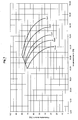
- FIG. 3 shows the course of the respective compressor characteristics for different gas compositions according to FIG. 1, as the course from a surge limit controller without knowing the actual Gas composition is detected. For every gas mixture it results another characteristic curve with a different surge limit point. From the Pump surge point in Fig. 1 are different surge point, that can be connected by a line. From the Pump limit point in Fig. 1 thus becomes a "fictitious" Surge limit line.
- the fictitious can be found within the surge limit control Simulate the surge line and the protection system of the compressor (Surge limit control), a control line according to the "fictitious" Pump limit line can be specified.
- This will be normal characteristics the surge limit control used.
- Each surge limit control is e.g. designed a variable speed compressor or variable geometry. Any such compressor will by a map with different speed characteristics or different geometries (guide vane position or Throttle position). Each of the characteristics of one such "normal" compressor ends in a surge limit. The connection of such surge limit points results in Surge limit line.
- the surge limit controller therefore does not need any additional features in order to also the case of any variable gas composition with fixed Cover geometry and fixed speed.
- the process works according to the method that the Control error that occurs in the surge limit controller of a compressor due to the unknown gas composition results in the determination of the "fictitious" surge limit is predetermined.
- the surge limit controller will errors that inevitably result in advance by the provided computer, in which the occurring Error has been taken into account in advance.
- the compressor can by taking into account the errors that occur safe when operating a compressor with different gases and be protected precisely, even if the gas composition of the actually extracted gas is not known at all.
- the method can also be applied to a compressor, whose characteristic curve is dependent on the 2 has gas composition.
- a compressor whose characteristic curve is dependent on the 2 has gas composition.
- the Sizes delta h and V for the surge limit controller are intended as examples the data for the gas composition are used with which the compressor is operated frequently.
- the corresponding Data are those according to the upper characteristic curve in FIG. 2.
- FIG. 4 corresponds the representation in Fig. 3. In both cases there is a "Fictitious" surge line, which has universal validity, too if the composition of the gas currently being extracted is not is known.
- the "fictitious" surge line according to FIGS. 3 and 4 can be used derive a universal control line that the compressor too without knowledge of the gas composition in the entire area of application optimally protects.
- surge limit control is the compressor always operate as close as possible to the surge line. To becomes a control difference from the minimum permissible flow and current flow and the surge limit controller switched.
- the fictitious surge limit control line is given by the Formation of a system deviation such a course that the arithmetic errors occurring due to the unknown quantities R, k and z of a gas composition when determining delta h and current volume flow V cancel each other out.
- the compressor is always adequately protected against operation in the unstable map area, even if the gas composition fluctuates significantly is subject.
- turbo compressors in particular multi-stage machines, in particular the course of the Pump limit line in the map depends on the Gas composition.
- variable geometry or variable speed and variable Gas composition can apply to any gas composition different course of the surge line or the surge line result. From the surge line or the surge line becomes a bevy of surge line and surge line control lines.
- Each characteristic of the original map (Fig. 5) is after the previously described procedure for the different Predetermined gas compositions. From the surge limit of Characteristic curve results in a surge line that is only valid for this speed or this throttle valve position or Has guide vane position. An application of this procedure on all characteristics of the original map leads to a family of Surge limit lines. Each of these lines applies to a speed or Guide vane position or throttle valve position. Because speed and position of the throttle valve or guide vane by measurement The surge limit controller can always be easily detected for the respective speed and throttle valve position or Guide vane position valid pump limit line can be specified. Between the characteristic curves can be done via the central computer unit be interpolated so that the default is limited Number of characteristic curves must take place.
- One advantage of the simplified approach is that it is a classic one Pump limit control without any modification to protect such Compressors can be used. To do this are preferred the required surge limit points for the different Compressor geometries or speeds and the possible Gas compositions in a common map consider. This results in a surge limit band.
- the Course of the surge limit line decisive for the surge limit control results from a connection of the farthest right, i.e. with the largest volume flows Surge points. This ensures that independent on the gas composition that is driven but is unknown a sufficient safety distance from the current surge limit consists.
- FIG. 6 shows the two characteristic diagrams of a surge limit control percentage nominal speed for two gases.
- the fictitious surge line or the universal surge line By changing the gas composition the fictitious surge line or the universal surge line to a map of fictitious surge limit lines or more universal Rule lines.
Abstract
Description
Die Erfindung betrifft ein Verfahren zum sicheren Betreiben von Turbokompressoren mit einer Pumpgrenzregelung und einem Pumpgrenzregelventil, wobei der Kompressor Gase mit unterschiedlicher Zusammensetzung fördert und die Zusammensetzung des Gases (Molekulargewicht) das Kennfeld des Turbokompressors und damit die Lage der Pumpgrenze im Kennfeld beeinflußt.The invention relates to a method for the safe operation of Turbo compressors with one surge limit control and one Pump limit control valve, the compressor with gases different composition promotes and Composition of the gas (molecular weight) the map of the Turbo compressor and thus the position of the surge limit in the map affected.
Aus der DE 198 28 368 C2 ist ein Verfahren zum Betreiben von zwei- oder mehrstufigen Verdichtern bekannt, bei denen jede Verdichterstufe ein eigenes zwischen einer Druckleitung über eine Umblaseleitung und einer Ansaugleitung angeordnetes Pumpgrenzregelventil aufweist. Dabei bläst jeweils das Pumpgrenzregelventil in die Ansaugleitung der zugehörigen Verdichterstufe ab. Weiterhin ist jeweils ein Durchflußrechner zum Berechnen des Ansaugdurchflusses sowie ein Rechner für den minimalen zulässigen Solldurchfluß vorgesehen, der aus dem Enddruck oder der Förderhöhe ermittelt wird.DE 198 28 368 C2 describes a method for operating two or multi-stage compressors known, each of which Compressor stage over between a pressure line a blow-by line and a suction line arranged Pump surge control valve has. That blows in each case Pump limit control valve in the suction line of the associated Compressor stage. There is also a flow calculator to calculate the intake flow and a calculator for the minimum allowable target flow rate provided from the Final pressure or the delivery head is determined.
Weiter ist aus der EP 0 810 358 A2 ein Verfahren zum Regeln von
Gasdrücken eines Regenerators mit einer Gasentspannungsturbine
in der Rauchgasleitung mit einem Generator bekannt, wobei ein
Prozeßregler die Eintrittsarmaturen einer Gasentspannungsturbine
und/oder die Bypaßarmaturen öffnet oder die Bypaßarmaturen
drosselt. Dabei sind dem Prozeßregler mehrere Funktionsgeber
nachgeschaltet, welche die Stellgrößen für die nachgeschalteten
Armaturen vorgeben.Furthermore,
Darüber hinaus ist aus der DE 100 12 380 A1 ein Verfahren zum
Schutz eines Turbokompressors mit nachgeschaltetem Prozeß vor
einem Betrieb im instabilen Arbeitsbereich bekannt, wobei ein
Maschinenregler verwendet wird, der neben einem Pumpgrenzregler
gegebenenfalls einen Saugdruckregler, einen Enddruckregler und
einen Bypaßregler aufweist. Aus der Stellung eines den Durchfluß
zum Prozeß bestimmenden Stellorgans wird unter Berücksichtigung
von gegebenenfalls weiteren Einflußgrößen, wie
Kompressoransaugdruck und Kompressoraustrittsdruck und
Kompressoransaugtemperatur sowie dem Prozeßdruck, eine
Steuermatrix ermittelt. Anhand der Steuermatrix wird bei einer
schnellen transienten Arbeitspunktänderung die erforderliche
Position des Pumpgrenzregelventils sowie des Bypaßventils, des
Saugdruckregelventils und des Stellantriebes für die
Kompressoreintrittsschaufeln direkt ermittelt. Die ermittelte
Steuergröße wird dann dem Pumpgrenzregelventil, dem
Saugdruckregler, dem Enddruckregler und dem Bypaßregler direkt
als Stellgröße aufgeschaltet.In addition,
Weiterhin ist aus der EP 0 757 180 B1 ein Verfahren zur Vermeidung von Reglerinstabilitäten an Pumpgrenzregelungen zum Schutz eines Turboverdichters vor Pumpen bei groß gewählter Proportionalverstärkung des Pumpgrenzreglers mittels Abblasen über ein Abblaseventil bekannt. Die zeitliche Steuerung der Schließgeschwindigkeit des Abblaseventils erfolgt dabei durch einen asymmetrisch aufgebauten Gradientenbegrenzer, wobei in Öffnungsrichtung keine zeitliche Begrenzung wirksam ist. In Schließrichtung ist jedoch eine parametrierbare zeitliche Begrenzung des Schließvorganges des Abblaseventils vorgesehen.Furthermore, EP 0 757 180 B1 describes a method for Avoiding controller instabilities in surge limit controls for Protection of a turbocompressor against pumps with a large selection Proportional gain of the surge limit controller by blowing off known via a relief valve. The timing of the The blow-off valve closes at an asymmetrically constructed gradient limiter, whereby in Opening direction no time limit is effective. In However, the closing direction is a parameterizable time Limitation of the closing process of the relief valve is provided.
Bei den bekannten Verfahren wird davon ausgegangen, dass die Lage der Pumpgrenze im Kennfeld des Kompressors bekannt ist. Die Koordinaten des Arbeitspunktes im Kennfeld werden üblicherweise als Kompressionsarbeit oder Enthalpiedifferenz oder Förderhöhe über dem Ansaugvolumenstrom aufgetragen. Dabei müssen die Parameter der jeweiligen Größen ebenfalls bekannt sein.In the known methods it is assumed that the Location of the surge limit in the map of the compressor is known. The Coordinates of the working point in the map are usually as compression work or enthalpy difference or head plotted against the intake volume flow. The Parameters of the respective sizes can also be known.
Der vorliegenden Erfindung liegt die Aufgabe zugrunde, ein Verfahren zum sicheren Betreiben eines Turbokompressors anzugeben, der in der Lage ist, auch Gase mit unterschiedlicher Zusammensetzung sicher zu verarbeiten, die insbesondere hinsichtlich der Größen für die Gaskonstante R und den Isentropenexponent k nicht hinreichend bekannt ist.The present invention is based on the object Process for safely operating a turbo compressor specify that is able to also gases with different Safe to process composition, in particular with regard to the sizes for the gas constant R and the Isentropic exponent k is not well known.
Die zugrundeliegende Aufgabe wird dadurch gelöst, dass die verschiedenen Zusammensetzungen der Gase mit dem Einfluss auf die Lage der Pumpgrenze und damit auch auf die Lage der Pumpgrenzregellinie kompensiert werden, indem innerhalb der Pumpgrenzregelung für die Erfassung von Förderhöhe (Enthalpiedifferenz) Δ h und Volumenstrom V vorbestimmte Auslegungswerte für Gaskonstante R, Isentropenexponent k und Kompressibilitätszahl z verwendet werden und in Form einer vorbestimmten Pumpgrenzlinie (Fig. 2, Fig. 4) innerhalb der Pumpgrenzregelung abgebildet werden, wobei Sollwert und Istwert für die Pumpgrenzregelung aus der Abbildung ermittelt werden und der Kompressor mit den ermittelten Soll- und Istwerten für die Pumpgrenzregelung mit einem minimal erforderlichen Abstand zur Pumpgrenze betrieben wird.The underlying task is solved in that the different compositions of the gases with the influence on the location of the surge line and thus also the location of the Surge limit line can be compensated by within the Pump limit control for the detection of delivery head (Enthalpy difference) Δ h and volume flow V predetermined Design values for gas constant R, isentropic exponent k and Compressibility number z are used and in the form of a predetermined surge line (Fig. 2, Fig. 4) within the Pump limit control are mapped, with setpoint and actual value for the surge limit control can be determined from the figure and the compressor with the determined target and actual values for the Pump limit control with a minimum required distance from Pump limit is operated.
Weiterhin hat sich als vorteilhaft erwiesen, dass eine Anzahl von Kennlinien mit jeweils konstanter Drehzahl oder mit jeweils konstanter Geometrie (Leitschaufelstellung oder Stellung einer Drosselarmatur) abgebildet wird, wobei eine Kurvenschar jeweils mit Pumpgrenzregellinien für eine konstante Drehzahl oder konstante Kompressorgeometrie beschrieben wird, dass zwischen den verschiedenen Kurven interpoliert und die Pumpgrenzregellinie bei jeder Drehzahl oder Kompressorgeometrie korrekt ermittelt wird und der Pumpgrenzregler mit dem minimal erforderlichen Abstand zur Pumpgrenze betrieben wird.It has also proven advantageous that a number of characteristic curves with constant speed or with each constant geometry (guide vane position or position of a Throttle valve) is shown, with a family of curves each with surge limit control lines for a constant speed or constant compressor geometry describes that between interpolated the various curves and the Pump limit control line at any speed or compressor geometry is correctly determined and the surge limit controller with the minimum required distance to the surge line is operated.
Darüber hinaus hat sich als besonders vorteilhaft herausgestellt, dass anstelle der Interpolation zwischen verschiedenen Pumpgrenzregellinien eine einzige "fiktive" Regellinie abgebildet wird, deren Lage vom Kennfeld abhängig ist und von den am weitesten rechts liegenden Pumppunkten bestimmt wird.It has also proven to be particularly beneficial found that instead of interpolating between different surge limit control lines a single "fictitious" Control line is depicted, the location of which depends on the map and determined by the rightmost pump points becomes.
Alternativ ist das Verfahren zum sicheren Betreiben von Turbokompressoren mit einer Pumpgrenzregelung und einem Pumpgrenzregelventil in vorteilhafter Weise anwendbar, bei dem der Kompressor Gase mit unterschiedlicher Zusammensetzung fördert und die Zusammensetzung der einzelnen Gase (Molekulargewicht) das Kennfeld des Turbokompressors und damit die Lage der Pumpgrenze im Kennfeld unbeeinflußt läßt, wobei innerhalb der Pumpgrenzregelung für die Erfassung von Förderhöhe Δ h und Volumenstrom V ein vorbestimmter Auslegungswert für Gaskonstante R, Isentropenexponent k und Kompressibilitätszahl z verwendet wird und in Form einer vorbestimmten Pumpgrenzlinie (Fig. 1) innerhalb der Pumpgrenzregelung abgebildet wird, wobei der Sollwert für die Pumpgrenzregelung aus der Abbildung ermittelt und der Istwert aus erfaßten Meßgrößen berechnet werden und der Kompressor mit den ermittelten Soll- und Istwerten für die Pumpgrenzregelung mit einem minimal erforderlichen Abstand zur Pumpgrenze betrieben wird.Alternatively, the procedure for the safe operation of Turbo compressors with one surge limit control and one Pump limit control valve applicable in an advantageous manner, in which the compressor gases with different compositions promotes and the composition of the individual gases (Molecular weight) the map of the turbo compressor and thus leaves the position of the surge line in the map unaffected, whereby within the surge limit regulation for the detection of delivery head Δ h and volume flow V a predetermined design value for Gas constant R, isentropic exponent k and compressibility number z is used and in the form of a predetermined surge line (Fig. 1) is mapped within the surge limit control, wherein the setpoint for the surge limit control from the figure determined and the actual value calculated from the measured variables and the compressor with the determined target and Actual values for the surge limit control with a minimum required distance to the surge line is operated.
In der Pumpgrenzregelung als einer der wesentlichen Maschinenschutzeinrichtungen für Turbokompressoren wird von der Lage der Pumpgrenze im Kennfeld eines Kompressors Gebrauch gemacht. Innerhalb der Pumpgrenzregelung wird aus der Enthalpiedifferenz der minimal zulässige Durchfluß durch den Kompressor als Sollwert für den Pumpgrenzregler ermittelt. Bei Kenntnis von Enthalpiedifferenz und Volumenstrom ist dann eine korrekte Pumpgrenzregelung und damit ein sicherer Maschinenschutz möglich.One of the most important in the surge limit control Machine protection devices for turbo compressors is manufactured by Location of the surge limit in the map of a compressor made. Within the surge limit control, the Enthalpy difference the minimum permissible flow through the Compressor determined as setpoint for the surge limit controller. at Knowledge of enthalpy difference and volume flow is then one correct surge limit control and thus a safe one Machine protection possible.
Die Formeln zur Bestimmung der Koordinaten von
Enthalpiedifferenz delta h oder Δh und Volumenstrom V lauten:

R gleich Gaskonstante
k gleich Isentropenexponent
z gleich Kompressibilitätszahl
T1 gleich Temperatur Saugseite
p1 gleich Druck auf Saugseite
p2 gleich Druck auf Druckseite
K gleich Parametrierkonstante für Durchfluß
Δp1 gleich Differenzdruck über Wirkdrucksensor auf SaugseiteThe formulas for determining the coordinates of the enthalpy difference delta h or Δh and volume flow V are:
R equals gas constant
k is the isentropic exponent
z equals compressibility number
T 1 is the temperature of the suction side
p 1 equals pressure on the suction side
p 2 equals pressure on the pressure side
K is the parameterization constant for flow
Δp 1 equal to differential pressure via differential pressure sensor on the suction side
Die Parameter R und k sowie auch z sind von der Gaszusammensetzung abhängig. R ist die Gaskonstante, k ist der Isentropenexponent und z die Kompressibilitätszahl. Üblicherweise ist die Zusammensetzung des vom Kompressor verdichteten Gases bekannt. In den allermeisten Fällen wird nur ein Gas verdichtet, z.B. Luft, Stickstoff oder ein Prozessgas mit zeitlich unveränderlicher Zusammensetzung in einem chemischen Prozess. Die Größen R, k und z sind über die gesamte Betriebsdauer des Kompressors konstant und können daher als Konstanten in den Formeln zur Berechnung von Enthalpiedifferenz und Volumenstrom berücksichtigt werden. Die Größen Enthalpiedifferenz und Volumenstrom werden in diesem Fall physikalisch korrekt erfaßt.The parameters R and k as well as z are of the Gas composition dependent. R is the gas constant, k is the Isentropic exponent and z the compressibility number. Usually the composition is that of the compressor compressed gas known. In most cases only compresses a gas, e.g. Air, nitrogen or a process gas with time-constant composition in one chemical process. The sizes R, k and z are over the whole Operating time of the compressor constant and can therefore be considered Constants in the formulas for calculating the enthalpy difference and volume flow are taken into account. The sizes The enthalpy difference and volume flow are in this case physically correctly recorded.
In einigen Anwendungen, insbesondere in der chemischen Industrie, sind jedoch auch Verfahren bekannt, in denen sich die Zusammensetzung des Gases über die Zeit ändern kann. Die Größen R, k und z sind dann nicht mehr konstant, sondern diese müssen als zeitlich veränderliche Variable betrachtet werden. Sofern die Größen R, k und z jeweils als bekannt vorauszusetzen oder jederzeit meßtechnisch genau bestimmbar sind, können diese innerhalb der zugrundeliegenden Formeln berücksichtigt werden. Enthalpiedifferenz und Volumenstrom werden dann auch in diesen Fällen jeweils physikalisch korrekt bestimmt. Ein sicherer Maschinenschutz mittels korrekt ermittelter Größen für Sollwert und Istwert ist möglich.In some applications, especially chemical Industry, however, are also known processes in which the The composition of the gas can change over time. The sizes R, k and z are then no longer constant, but must be are regarded as a variable that changes over time. Provided the sizes R, k and z are assumed to be known or can be precisely determined at any time, these can be taken into account within the underlying formulas. The enthalpy difference and volume flow are then also in these Cases physically correctly determined. A safe one Machine protection by means of correctly determined values for the setpoint and actual value is possible.
In anderen Anwendungsfällen werden dagegen Kompressoren mit variabler Gaszusammensetzung betrieben, deren Zusammensetzung im Einzelfall nicht bekannt ist. Je nach Zusammensetzung des Gases ergibt sich bei verschiedenen Kompressoren ein anderer Verlauf der Pumpgrenze, der innerhalb der Pumpgrenzregelung zu berücksichtigen ist. Ohne Kenntnis der Gasparameter R, k und z ist die Berücksichtigung eines anderen Verlaufs der Pumpgrenze jedoch normalerweise nicht möglich.In other applications, compressors are used variable gas composition operated, the composition in the Individual case is not known. Depending on the composition of the gas there is a different course for different compressors the surge limit, which increases within the surge limit control is considered. Without knowing the gas parameters R, k and z is the consideration of a different course of the surge limit however usually not possible.
Das vorliegende Verfahren ist deshalb bei den Kompressoren einzusetzen, bei denen der Verlauf der Pumpgrenze bzw. der Pumpgrenzregellinie im Kennfeld eine Abhängigkeit von zumindest einer Gaszusammensetzung aufweist.The present procedure is therefore with the compressors to be used for which the course of the surge limit or the Surge limit control line in the map a dependency of at least a gas composition.
Nachfolgend wird ein Verfahren angegeben, mit dessen Hilfe es möglich ist, auch bei fehlender Kenntnis der Gaszusammensetzung die Differenz aus Sollwert und Istwert für die Pumpgrenzregelung exakt zu bestimmen und damit den Kompressor optimal vor einem Betrieb im instabilen Bereich zu schützen.A method is given below with the aid of which it is possible, even if the gas composition is not known the difference between the setpoint and actual value for the surge limit control to determine exactly and thus the compressor optimally in front of you Protect operation in an unstable area.
Das Verfahren wird nachfolgend anhand von Ausführungsbeispielen beschrieben, deren charakteristische Kennlinien jeweils dargestellt sind. Zum besseren Verständnis wird das Verfahren zunächst für einen Kompressor mit konstanter Drehzahl und konstanter Geometrie (feste Leitschaufeln und ohne Drosselarmatur) beschrieben. Anschließend wird das Verfahren verallgemeinert für beliebige Kompressoren. Es zeigen:
- Fig. 1
- die Kennlinie eines Kompressors mit konstanter Drehzahl und feststehender Geometrie;
- Fig. 2
- Kennlinien eines Kompressors für zwei Gase;
- Fig. 3
- Kennlinien eines Kompressors für fünf verschiedene Gase;
- Fig. 4
- Kennlinien eines Kompressors für ähnlich verschiedene Gase wie in Fig. 3;
- Fig. 5
- Kennlinien eines Kompressors für verschiedene Winkel der verstellbaren Leitschaufeln;
- Fig. 6
- Kennlinien eines Kompressors bei prozentualer Nenndrehzahl für zwei Gase und
- Fig. 7
- Regelkennlinien eines Kompressors mit Pumpgrenzen zweier Gase und eine gewählte Regellinie.
- Fig. 1
- the characteristic of a compressor with constant speed and fixed geometry;
- Fig. 2
- Characteristics of a compressor for two gases;
- Fig. 3
- Characteristic curves of a compressor for five different gases;
- Fig. 4
- Characteristic curves of a compressor for similarly different gases as in Fig. 3;
- Fig. 5
- Characteristic curves of a compressor for different angles of the adjustable guide vanes;
- Fig. 6
- Characteristic curves of a compressor at percentage nominal speed for two gases and
- Fig. 7
- Control characteristics of a compressor with surge limits of two gases and a selected control line.
Fig. 1 zeigt die Kennlinie eines Kompressors mit konstanter Drehzahl und feststehender Geometrie. Fig. 1 shows the characteristic of a compressor with constant Speed and fixed geometry.
Es gibt Kompressoren, bei denen das Kennfeld gemäß Fig. 1 unabhängig von der Gaszusammensetzung ist. Die Kennlinie im Kennfeld delta h über V ist derart ausgebildet, dass diese allgemeine Gültigkeit für alle geförderten Gase besitzt.There are compressors in which the map according to FIG. 1 is independent of the gas composition. The characteristic in Map delta h over V is designed such that this has general validity for all extracted gases.
Andere Kompressoren sind derart konstruiert, dass sich für jede Gaszusammensetzung eine andere Kennlinie mit einem anderen Pumpgrenzpunkt ergibt.Other compressors are designed in such a way that each Gas composition a different characteristic with another Pump limit point results.
Fig. 2 zeigt beispielsweise die Kennlinie eines Kompressors, dessen Kennlinienverlauf und damit auch die Lage des Pumpgrenzpunktes abhängig ist von der Gaszusammensetzung.2 shows, for example, the characteristic curve of a compressor, its characteristic curve and thus also the location of the The surge limit depends on the gas composition.
Der wesentliche Unterschied zwischen dem Fall gemäß Fig. 1 und Fig. 2 besteht nun darin, dass bei einer universell gültigen Kennlinie gemäß Fig. 1 die Kennlinie und damit der Pumpgrenzpunkt nur für eine Gaszusammensetzung errechnet zu werden braucht. Bei den Abnahmemessungen im Prüffeld braucht der Verlauf der Kennlinie nur für ein Gas verifiziert zu werden.The main difference between the case of FIG. 1 and Fig. 2 now consists in that at a universally valid 1 the characteristic and thus the Pumping limit point only calculated for a gas composition are needed. For the acceptance measurements in the test field, the Characteristic curve to be verified only for one gas.
Wenn für jede Gaszusammensetzung, wie in Fig. 2 gezeigt, eine andere Kennlinie wirksam wird, ist der Kompressor thermodynamisch für alle vorkommenden Gaszusammensetzungen oder zumindest für einige repräsentative Gaszusammensetzungen auszulegen. Im Prüffeld sind die Kennlinien dann durch entsprechende Messungen mit verschiedenen Gasen zu verifizieren.If for each gas composition, as shown in Fig. 2, one other characteristic is effective is the compressor thermodynamic for all occurring gas compositions or at least for some representative gas compositions interpreted. The characteristic curves are then through in the test field verify corresponding measurements with different gases.
Für das nachfolgend beschriebene Verfahren ist der aufgezeigte Unterschied nicht von besonderer Bedeutung. Der Unterschied wird lediglich der Vollständigkeit halber erwähnt.For the method described below is the one shown Difference not of particular importance. The difference will be only mentioned for the sake of completeness.
Nachfolgend soll zunächst von einem Kompressor gemäß Fig. 1 ausgegangen werden. In the following, a compressor according to FIG be assumed.
Zur Bestimmung der Lage des Arbeitspunktes im Kennfeld ist die genaue Bestimmung von Förderhöhe delta h und Volumenstrom V erforderlich. Dadurch kann die Lage des aktuellen Arbeitspunktes relativ zum Pumpgrenzpunkt erfaßt werden. Das setzt aufgrund der bekannten Formeln für die Förderhöhe delta h und den Volumenstrom V eine genaue Kenntnis von den Größen R, k und z voraus. Diese Größen sind jedoch häufig nicht bekannt. Daher wird davon ausgegangen, dass die Größen R, k und z meßtechnisch nicht erfassbar und zur Bestimmung von delta h und V nicht als bekannt einzusetzen sind. Bei der Bestimmung des Arbeitspunktes kann demnach nur ein einziger Parametersatz für R, k und z herangezogen werden. Unterschiedliche Parametersätze können nicht verwendet werden, da kein Kriterium vorliegt, nach dem zwischen den verschiedenen Parametersätzen umgeschaltet werden kann.To determine the position of the operating point in the map, the exact determination of delivery head delta h and volume flow V required. This allows the location of the current working point relative to the surge limit point. That sets due to the known formulas for the delivery head delta h and the Volume flow V a precise knowledge of the sizes R, k and z ahead. However, these sizes are often not known. Therefore it is assumed that the quantities R, k and z are measured not detectable and not to be used to determine delta h and V are known to be used. When determining the working point can therefore only a single parameter set for R, k and z be used. Different parameter sets can not be used because there is no criterion according to which can be switched between the different parameter sets can.
Üblicherweise werden zur Umschaltung auf verschiedene Parametersätze die Daten der Gaszusammensetzung verwendet, mit welcher der Kompressor die meiste Zeit betrieben wird, oder es werden die Werte der Gaszusammensetzung verwendet, für die der Kompressor ausgelegt wurde (nachfolgend auch Auslegungswerte genannt). Solange das geförderte Gas in seiner Zusammensetzung genau der Auslegung entspricht, wird die Lage des Arbeitspunktes im Kennfeld auch korrekt erfaßt.Usually to switch to different Parameter sets using the data of the gas composition which the compressor is operated most of the time, or it the gas composition values for which the Compressor was designed (hereinafter also design values called). As long as the extracted gas in its composition The position of the working point corresponds exactly to the design also correctly recorded in the map.
Hat sich dagegen die Zusammensetzung des Gases geändert, kann wegen der meßtechnisch nicht erfaßbaren Größen R, k und z ein vorgesehener Rechner zur Bestimmung von Förderhöhe delta h und Volumenstrom V diese Werte nicht mehr korrekt bestimmen. Statt der korrekten Werte für R, k und z verwendet der Rechner lediglich nicht korrekt vorgegebene Werte. Es stellt sich ein Fehler ein, dessen Größe abhängig ist von der Abweichung der aktuellen Gaszusammensetzung von den in den Berechnungsformeln für delta h und V verwendeten Auslegungswerten.However, if the composition of the gas has changed, it can because of the quantities R, k and z which cannot be measured provided computer for determining the delivery head delta h and Volume flow V no longer correctly determine these values. Instead of the computer uses the correct values for R, k and z only incorrectly specified values. It sets in Error, the size of which depends on the deviation of the current gas composition from those in the calculation formulas design values used for delta h and V.
Die Kennlinie aus Fig. 1 läßt sich unter Kenntnis der angenommenen Fehler aufgrund der meßtechnisch nicht erfaßbaren Größen von R, k und z in "fiktive" Kennlinien umwandeln. Dann entstehen die Kennlinien, die der Pumpgrenzregler unter Verwendung der nicht korrekt vorgegebenen Werte für R, k und z ermittelt.1 can be seen with knowledge of the assumed errors due to the non-measurable Convert sizes of R, k and z into "fictitious" characteristic curves. Then the characteristic curves are created which the surge limit controller under Use of the incorrectly specified values for R, k and z determined.
Fig. 3 zeigt den Verlauf der jeweiligen Kompressorkennlinien für verschiedene Gaszusammensetzungen gemäß Fig. 1, wie der Verlauf von einem Pumpgrenzregler ohne Kenntnis der tatsächlichen Gaszusammensetzung erfaßt wird. Für jedes Gasgemisch ergibt sich eine andere Kennlinie mit einem anderen Pumpgrenzpunkt. Aus dem Pumpgrenzpunkt in Fig. 1 werden verschiedene Pumpgrenzpunkte, die sich durch eine Linie verbinden lassen. Aus dem Pumpgrenzpunkt in Fig. 1 wird somit eine "fiktive" Pumpgrenzlinie.3 shows the course of the respective compressor characteristics for different gas compositions according to FIG. 1, as the course from a surge limit controller without knowing the actual Gas composition is detected. For every gas mixture it results another characteristic curve with a different surge limit point. From the Pump surge point in Fig. 1 are different surge point, that can be connected by a line. From the Pump limit point in Fig. 1 thus becomes a "fictitious" Surge limit line.
Innerhalb der Pumpgrenzregelung läßt sich die fiktive Pumpgrenzlinie nachbilden, und dem Schutzsystem des Kompressors (Pumpgrenzregelung) kann eine Regellinie gemäß der "fiktiven" Pumpgrenzlinie vorgegeben werden. Hierzu werden normale Merkmale der Pumpgrenzregelung verwendet. Jede Pumpgrenzregelung ist z.B. ausgelegt, einen Kompressor mit variabler Drehzahl oder variabler Geometrie zu regeln. Jeder solcher Kompressoren wird durch ein Kennfeld mit verschiedenen Drehzahlkennlinien oder verschiedenen Geometrien (Leitschaufelstellung oder Drosselklappenstellung) beschrieben. Jede der Kennlinien eines solchen "normalen" Kompressors endet in einem Pumpgrenzpunkt. Die Verbindung solcher Pumpgrenzpunkte ergibt die Pumpgrenzlinie. Analog hierzu ergibt sich für einen Kompressor mit fester Geometrie und fester Drehzahl bei variabler Gaszusammensetzung eine Pumpgrenzlinie von gleicher Ausprägung. Der Pumpgrenzregler bedarf also keiner zusätzlichen Merkmale, um auch den Fall beliebiger variabler Gaszusammensetzung bei fester Geometrie und fester Drehzahl abzudecken.The fictitious can be found within the surge limit control Simulate the surge line and the protection system of the compressor (Surge limit control), a control line according to the "fictitious" Pump limit line can be specified. This will be normal characteristics the surge limit control used. Each surge limit control is e.g. designed a variable speed compressor or variable geometry. Any such compressor will by a map with different speed characteristics or different geometries (guide vane position or Throttle position). Each of the characteristics of one such "normal" compressor ends in a surge limit. The connection of such surge limit points results in Surge limit line. The same applies to a compressor with fixed geometry and fixed speed at variable Gas composition a surge line of the same characteristics. The surge limit controller therefore does not need any additional features in order to also the case of any variable gas composition with fixed Cover geometry and fixed speed.
Das Verfahren arbeitet nach der Methode, dass der Regelungsfehler, der sich beim Pumpgrenzregler eines Kompressors aufgrund der nicht bekannten tatsächlichen Gaszusammensetzung ergibt, bei der Ermittlung der "fiktiven" Pumpgrenze vorherbestimmt wird. Dem Pumpgrenzregler wird der sich zwangsläufig ergebende Fehler somit vorab überlagernd durch den vorgesehenen Rechner aufgeschaltet, bei dem der auftretende Fehler vorab berücksichtigt worden ist. Der Kompressor kann durch die vorherige Berücksichtigung der auftretenden Fehler beim Betrieb eines Kompressors mit verschiedenen Gasen sicher und genau geschützt werden, auch wenn die Gaszusammensetzung des tatsächlich geförderten Gases gar nicht bekannt ist.The process works according to the method that the Control error that occurs in the surge limit controller of a compressor due to the unknown gas composition results in the determination of the "fictitious" surge limit is predetermined. The surge limit controller will errors that inevitably result in advance by the provided computer, in which the occurring Error has been taken into account in advance. The compressor can by taking into account the errors that occur safe when operating a compressor with different gases and be protected precisely, even if the gas composition of the actually extracted gas is not known at all.
Das Verfahren läßt sich auch bei einem Kompressor anwenden, dessen Kennlinienverlauf eine Abhängigkeit von der Gaszusammensetzung gemäß Fig. 2 aufweist. Für die Bestimmung der Größen delta h und V beim Pumpgrenzregler sollen beispielhaft die Daten für die Gaszusammensetzung verwendet werden, mit welcher der Kompressor häufig betrieben wird. Die entsprechenden Daten seien die gemäß der oberen Kennlinie in Fig. 2.The method can also be applied to a compressor, whose characteristic curve is dependent on the 2 has gas composition. For the determination of the Sizes delta h and V for the surge limit controller are intended as examples the data for the gas composition are used with which the compressor is operated frequently. The corresponding Data are those according to the upper characteristic curve in FIG. 2.
In Fig. 4 sind ähnlich wie in Fig. 3 fünf Kennlinien aufgetragen. Die obere Kennlinie entspricht exakt der oberen Kennlinie gemäß Fig. 3. Die anderen Kennlinien sind gegenüber denen in Fig. 3 verschoben. Die Kennlinien wurden derart umgewandelt, dass statt der korrekten Werte für R, k und z die gleichen Werte eingesetzt wurden, wie sie für die anderen Kennlinien gelten. Damit entspricht die Darstellung in Fig. 4 der Darstellung in Fig. 3. In beiden Fällen ergibt sich eine "fiktive" Pumpgrenze, die universelle Gültigkeit besitzt, auch wenn die Zusammensetzung des aktuell geförderten Gases nicht bekannt ist.In Fig. 4, five characteristics are similar to Fig. 3 applied. The upper characteristic curve corresponds exactly to the upper one Characteristic curve according to FIG. 3. The other characteristic curves are opposite those shifted in Fig. 3. The characteristics became like this converted that instead of the correct values for R, k and z the same values were used as for the others Characteristic curves apply. The representation in FIG. 4 thus corresponds the representation in Fig. 3. In both cases there is a "Fictitious" surge line, which has universal validity, too if the composition of the gas currently being extracted is not is known.
Aus der "fiktiven" Pumpgrenzlinie gemäß Fig. 3 und 4 lässt sich eine universelle Regellinie herleiten, die den Kompressor auch ohne Kenntnis der Gaszusammensetzung im gesamten Einsatzbereich optimal schützt.The "fictitious" surge line according to FIGS. 3 and 4 can be used derive a universal control line that the compressor too without knowledge of the gas composition in the entire area of application optimally protects.
Es ist gleichgültig, welcher Parametersatz für welche Gaszusammensetzung verwendet wird, wichtig ist lediglich, dass stets der gleiche Parametersatz verwendet wird.It does not matter which parameter set for which Gas composition is used, it is only important that the same parameter set is always used.
Der Zweck der Pumpgrenzregelung besteht darin, den Kompressor stets so dicht wie möglich an der Pumpgrenze zu betreiben. Dazu wird eine Regeldifferenz aus minimal zulässigem Durchfluss und aktuellem Durchfluss gebildet und dem Pumpgrenzregler aufgeschaltet. Die fiktive Pumpgrenzregellinie erhält durch die Bildung einer Regeldifferenz einen derartigen Verlauf, dass die auftretenden Rechenfehler aufgrund der nicht bekannten Größen R, k und z einer Gaszusammensetzung bei der Bestimmung von delta h und aktuellem Volumenstrom V sich gegenseitig aufheben.The purpose of surge limit control is the compressor always operate as close as possible to the surge line. To becomes a control difference from the minimum permissible flow and current flow and the surge limit controller switched. The fictitious surge limit control line is given by the Formation of a system deviation such a course that the arithmetic errors occurring due to the unknown quantities R, k and z of a gas composition when determining delta h and current volume flow V cancel each other out.
Wird die so ermittelte Pumpgrenzregellinie innerhalb der Pumpgrenzregelung verwendet, ist der Kompressor stets ausreichend vor Betrieb im instabilen Kennfeldbereich geschützt, auch wenn die Gaszusammensetzung größeren Schwankungen unterworfen ist.If the surge limit line thus determined is within the Pump limit control is used, the compressor is always adequately protected against operation in the unstable map area, even if the gas composition fluctuates significantly is subject.
Etwas aufwendiger wird das Verfahren, wenn der Kompressor mit variabler Drehzahl bzw. mit variabler Geometrie (Leitschaufeln, Dralldrossel oder Drosselarmatur) und variabler Gaszusammensetzung betrieben wird. Bei Kompressoren einer solchen Bauart ergibt sich allein bei konstanter Gaszusammensetzung schon eine Pumpgrenzlinie bzw. eine Pumpgrenzregellinie. Bekanntermaßen darf der Kompressor niemals jenseits, d.h. links der Pumpgrenzlinie betrieben werden. Damit dies sichergestellt werden kann, wird eine Regellinie rechts von der Pumpgrenze in ausreichendem Sicherheitsabstand derart positioniert, dass der Pumpgrenzregler auch unter extremen Betriebsbedingungen den Kompressor stets außerhalb des Pumpgrenzbereichs betreiben kann.The process becomes somewhat more complex if the compressor is used variable speed or with variable geometry (guide vanes, Swirl throttle or throttle valve) and more variable Gas composition is operated. One with compressors such a construction results only with constant Gas composition already a surge line or Surge limit line. As is known, the compressor must never beyond, i.e. to the left of the surge line. In order to this can be ensured, a rule line is to the right of the surge line with a sufficient safety margin positioned that the surge limit controller even under extreme Operating conditions always the compressor outside the Pump limit range can operate.
Es gibt eine ganze Reihe von Turbokompressoren, insbesondere vielstufige Maschinen, bei denen insbesondere der Verlauf der Pumpgrenzlinie im Kennfeld abhängig ist von der Gaszusammensetzung.There are quite a number of turbo compressors, in particular multi-stage machines, in particular the course of the Pump limit line in the map depends on the Gas composition.
Bei variabler Geometrie bzw. variabler Drehzahl und variabler Gaszusammensetzung kann sich für jede Gaszusammensetzung ein anderer Verlauf der Pumpgrenzlinie bzw. der Pumpgrenzregellinie ergeben. Aus der Pumpgrenzlinie bzw. der Pumpgrenzregellinie wird eine Schar von Pumpgrenzlinien und Pumpgrenzregellinien.With variable geometry or variable speed and variable Gas composition can apply to any gas composition different course of the surge line or the surge line result. From the surge line or the surge line becomes a bevy of surge line and surge line control lines.
Jede Kennlinie des ursprünglichen Kennfelds (Fig. 5) wird nach dem zuvor beschriebenen Verfahren für die verschiedenen Gaszusammensetzungen vorherbestimmt. Aus dem Pumpgrenzpunkt der Kennlinie ergibt sich eine Pumpgrenzlinie, die nur Gültigkeit für diese Drehzahl bzw. diese Drosselklappenstellung oder Leitschaufelstellung hat. Eine Anwendung dieses Verfahrens auf alle Kennlinien des Ursprungskennfelds führt zu einer Schar von Pumpgrenzlinien. Jede dieser Linien gilt für eine Drehzahl oder Leitschaufelstellung oder Drosselklappenstellung. Da Drehzahl und Stellung der Drosselklappe oder Leitschaufel meßtechnisch einfach erfasst werden können, kann dem Pumpgrenzregler stets die für die jeweilige Drehzahl und Drosselklappenstellung oder Leitschaufelstellung gültige Pumpgrenzlinie vorgegeben werden. Zwischen den Kennlinien kann über die zentrale Rechnereinheit interpoliert werden, so dass die Vorgabe nur für eine begrenzte Zahl von Kennlinien erfolgen muss.Each characteristic of the original map (Fig. 5) is after the previously described procedure for the different Predetermined gas compositions. From the surge limit of Characteristic curve results in a surge line that is only valid for this speed or this throttle valve position or Has guide vane position. An application of this procedure on all characteristics of the original map leads to a family of Surge limit lines. Each of these lines applies to a speed or Guide vane position or throttle valve position. Because speed and position of the throttle valve or guide vane by measurement The surge limit controller can always be easily detected for the respective speed and throttle valve position or Guide vane position valid pump limit line can be specified. Between the characteristic curves can be done via the central computer unit be interpolated so that the default is limited Number of characteristic curves must take place.
Ein anderer, einfacherer Ansatz verzichtet auf die Messung von Drehzahl und Leitschaufelstellung oder Drosselklappenstellung. Hierdurch wird der apparative Aufwand einfacher und damit das Gesamtsystem kostengünstiger, allerdings wird der nutzbare Kennfeldbereich etwas eingeschränkt, da bei diesem Verfahren stets vom ungünstigsten Fall ausgegangen wird.Another, simpler approach does not measure Speed and vane position or throttle position. This simplifies the outlay in terms of equipment, and thus that The entire system is cheaper, but the usable one Map area somewhat limited because of this procedure the worst case scenario is always assumed.
Ein Vorteil des vereinfachten Ansatzes ist, dass eine klassische Pumpgrenzregelung ohne jegliche Modifikation zum Schutz solcher Kompressoren eingesetzt werden kann. Hierzu sind vorzugsweise die erforderlichen Pumpgrenzpunkte für die verschiedenen Kompressorgeometrien bzw. Drehzahlen und die möglichen Gaszusammensetzungen in einem gemeinsamen Kennfeld zu berücksichtigen. Hierdurch ergibt sich ein Pumpgrenzband. Der Verlauf der für die Pumpgrenzregelung maßgebenden Pumpgrenzlinie ergibt sich durch eine Verbindung der jeweils am weitesten rechts, d.h. bei den größten Volumenströmen liegenden Pumpgrenzpunkte. Hierdurch ist sichergestellt, dass unabhängig von der jeweils gefahrenen, aber unbekannten Gaszusammensetzung ein ausreichender Sicherheitsabstand zur aktuellen Pumpgrenze besteht.One advantage of the simplified approach is that it is a classic one Pump limit control without any modification to protect such Compressors can be used. To do this are preferred the required surge limit points for the different Compressor geometries or speeds and the possible Gas compositions in a common map consider. This results in a surge limit band. The Course of the surge limit line decisive for the surge limit control results from a connection of the farthest right, i.e. with the largest volume flows Surge points. This ensures that independent on the gas composition that is driven but is unknown a sufficient safety distance from the current surge limit consists.
Fig. 6 zeigt die beiden Kennfelder einer Pumpgrenzregelung bei prozentualer Nenndrehzahl für zwei Gase. 6 shows the two characteristic diagrams of a surge limit control percentage nominal speed for two gases.
Fig. 7 zeigt die Lage der vorherbestimmten "fiktiven" Pumpgrenzlinien für die beiden Gase sowie die zugehörige gewählte Regellinie, deren Lage sich an der am weitesten rechts liegenden Pumpgrenze orientiert.7 shows the position of the predetermined "fictitious" Pump limit lines for the two gases and the associated one selected control line, the location of which is at the rightmost oriented surge line.
Durch die Änderung der Gaszusammensetzung erweitert sich die fiktive Pumpgrenzlinie bzw. die universelle Pumpgrenzregellinie zu einem Kennfeld fiktiver Pumpgrenzlinien bzw. universeller Regellinien.By changing the gas composition the fictitious surge line or the universal surge line to a map of fictitious surge limit lines or more universal Rule lines.
Dargestellt sind die Kennfelder fiktiver Pumpgrenzlinien oder universeller Regellinien in den Fig. 5 und 6. Aus der Kennlinie in Fig. 1 wird aufgrund der variablen Drehzahl bzw. der variablen Geometrie das Kennfeld gemäß Fig. 5. Jede dieser Kennlinien (für feste Gaszusammensetzung) gemäß Fig. 5 läßt sich nach dem oben beschriebenen Verfahren in ein Kennfeld (für variable Gaszusammensetzung) umwandeln. Da jede der Kennlinien durch einen Pumppunkt begrenzt wird, ergibt sich in jedem der Kennfelder eine Pumpgrenzlinie. Da jede Kennlinie in Fig. 5 durch eine feste Drehzahl und eine feste Kompressorgeometrie gekennzeichnet ist, wird auch jedes Kennfeld in Fig. 6 und damit jede Pumpgrenzlinie in Fig. 6 durch eine feste Drehzahl und eine feste Kompressorgeometrie charakterisiert.The maps of fictitious surge limit lines or are shown universal control lines in FIGS. 5 and 6. From the characteristic in Fig. 1 is due to the variable speed or variable geometry the map according to FIG. 5. Each of these Characteristic curves (for solid gas composition) according to FIG. 5 can be into a map (for variable gas composition). Because each of the characteristics is limited by a pump point, in each of the results Maps of a surge line. Since each characteristic curve in FIG. 5 due to a fixed speed and a fixed compressor geometry is marked, each map in Fig. 6 and thus each surge line in Fig. 6 by a fixed speed and a characterized compressor geometry.
Da sowohl Drehzahl als auch Kompressorgeometrie (veränderbar durch verstellbare Leitschaufeln oder Drosselarmaturen) meßtechnisch leicht erfassbar sind, kann durch Messung der Drehzahl und der Kompressorgeometrie stets die für die jeweilige Betriebsweise relevante Kennlinie ausgewählt werden.Since both speed and compressor geometry (changeable with adjustable guide vanes or throttle fittings) can be easily measured by measuring the Speed and the compressor geometry always the one for the respective Relevant characteristic can be selected.
Dabei können Betriebspunkte zwischen zwei Kennlinien durch numerische Interpolation genau bestimmt werden.Operating points can pass through between two characteristic curves numerical interpolation can be determined exactly.
Claims (4)
Applications Claiming Priority (2)
| Application Number | Priority Date | Filing Date | Title |
|---|---|---|---|
| DE10304063A DE10304063A1 (en) | 2003-01-31 | 2003-01-31 | Method for the safe operation of turbo compressors with a surge limit control and a surge limit control valve |
| DE10304063 | 2003-01-31 |
Publications (3)
| Publication Number | Publication Date |
|---|---|
| EP1450046A2 true EP1450046A2 (en) | 2004-08-25 |
| EP1450046A3 EP1450046A3 (en) | 2005-10-26 |
| EP1450046B1 EP1450046B1 (en) | 2008-02-27 |
Family
ID=32695125
Family Applications (1)
| Application Number | Title | Priority Date | Filing Date |
|---|---|---|---|
| EP04000580A Expired - Lifetime EP1450046B1 (en) | 2003-01-31 | 2004-01-14 | Method for operation of turbocompressors with surge limitation regulation |
Country Status (4)
| Country | Link |
|---|---|
| US (1) | US7025558B2 (en) |
| EP (1) | EP1450046B1 (en) |
| AT (1) | ATE387584T1 (en) |
| DE (2) | DE10304063A1 (en) |
Cited By (1)
| Publication number | Priority date | Publication date | Assignee | Title |
|---|---|---|---|---|
| WO2009092409A1 (en) * | 2008-01-21 | 2009-07-30 | Man Turbo Ag | Method for regulating a turbomachine |
Families Citing this family (12)
| Publication number | Priority date | Publication date | Assignee | Title |
|---|---|---|---|---|
| DE102008058799B4 (en) * | 2008-11-24 | 2012-04-26 | Siemens Aktiengesellschaft | Method for operating a multi-stage compressor |
| DE102009003978A1 (en) | 2009-01-07 | 2010-07-08 | Man Turbo Ag | Method for determining e.g. molecular weight, of carrier gas using turbo compressor, involves presetting new value for property of gas based on comparison of mathematical parameter and characteristic field parameter |
| EP2322877A3 (en) * | 2009-10-20 | 2015-05-27 | Johnson Controls Technology Company | Controllers and methods for providing computerized generation and use of a three dimensional surge map for control of chillers |
| DE102011008165A1 (en) * | 2011-01-10 | 2012-07-12 | Wilo Se | Procedures for the performance-optimized operation of an electric motor-driven pump at low flow rates |
| EP2693059A4 (en) * | 2011-03-31 | 2014-11-12 | Mitsubishi Heavy Ind Ltd | Method for operating gas compressor, and gas turbine provided with gas compressor |
| US9074606B1 (en) | 2012-03-02 | 2015-07-07 | Rmoore Controls L.L.C. | Compressor surge control |
| KR101858643B1 (en) * | 2012-03-23 | 2018-05-16 | 한화테크윈 주식회사 | Method of controlling compressor system and compressor system for protecting surge |
| US9097447B2 (en) | 2012-07-25 | 2015-08-04 | Johnson Controls Technology Company | Methods and controllers for providing a surge map for the monitoring and control of chillers |
| ITCO20120056A1 (en) * | 2012-11-07 | 2014-05-08 | Nuovo Pignone Srl | METHOD OF OPERATING A COMPRESSOR IN CASE OF MALFUNCTION OF ONE OR MORE SIZES OF MEASUREMENT |
| US20220364571A1 (en) * | 2021-04-29 | 2022-11-17 | Emerson Climate Technologies, Inc. | Mass flow interpolation systems and methods for dynamic compressors |
| CN114870422B (en) * | 2022-05-12 | 2024-03-01 | 梅胜 | Fractionating tower top pressure control method and device based on air pressure unit |
| CN116357607B (en) * | 2023-06-02 | 2023-08-22 | 杭州德玛仕气体设备工程有限公司 | One-key starting loading method for turbine compressor |
Citations (3)
| Publication number | Priority date | Publication date | Assignee | Title |
|---|---|---|---|---|
| US5195875A (en) * | 1991-12-05 | 1993-03-23 | Dresser-Rand Company | Antisurge control system for compressors |
| US5908462A (en) * | 1996-12-06 | 1999-06-01 | Compressor Controls Corporation | Method and apparatus for antisurge control of turbocompressors having surge limit lines with small slopes |
| US20020062679A1 (en) * | 2000-06-20 | 2002-05-30 | Petr Petrosov | Method and apparatus of molecular weight determination for gases flowing through the compressor |
Family Cites Families (18)
| Publication number | Priority date | Publication date | Assignee | Title |
|---|---|---|---|---|
| CH599460A5 (en) * | 1975-12-23 | 1978-05-31 | Bbc Brown Boveri & Cie | |
| DE3540087A1 (en) * | 1985-11-12 | 1987-05-14 | Gutehoffnungshuette Man | METHOD FOR REGULATING TURBO COMPRESSORS |
| DE3544822A1 (en) * | 1985-12-18 | 1987-06-19 | Gutehoffnungshuette Man | METHOD FOR CONTROLLING PUMP LIMITS OF TURBO COMPRESSORS |
| US4825380A (en) * | 1987-05-19 | 1989-04-25 | Phillips Petroleum Company | Molecular weight determination for constraint control of a compressor |
| DE3809881A1 (en) * | 1988-03-24 | 1989-10-12 | Gutehoffnungshuette Man | CONTROL METHOD FOR AVOIDING THE PUMPING OF A TURBO COMPRESSOR |
| US4949276A (en) * | 1988-10-26 | 1990-08-14 | Compressor Controls Corp. | Method and apparatus for preventing surge in a dynamic compressor |
| DE4202226C2 (en) * | 1991-10-01 | 1995-06-08 | Atlas Copco Energas | Method for monitoring a multi-stage, intercooled turbocompressor |
| IT1255836B (en) * | 1991-10-01 | 1995-11-17 | PROCEDURE FOR THE SURVEILLANCE OF THE PUMPING LIMIT OF MULTI-STAGE TURBOCHARGERS AND INTERMEDIATE REFRIGERATION | |
| DE4316202C2 (en) * | 1993-05-14 | 1998-04-09 | Atlas Copco Energas | Process for monitoring the surge line of a turbocompressor with a pre-guide and a post-guide |
| JPH0712090A (en) * | 1993-06-28 | 1995-01-17 | Mitsubishi Heavy Ind Ltd | Surging generation preventive method for compressor |
| DE19528253C2 (en) * | 1995-08-01 | 1997-10-16 | Gutehoffnungshuette Man | Method and device for avoiding controller instabilities in surge limit controls when operating turbomachines with controllers with high proportional gain |
| US5743715A (en) * | 1995-10-20 | 1998-04-28 | Compressor Controls Corporation | Method and apparatus for load balancing among multiple compressors |
| DE19621824C2 (en) * | 1996-05-31 | 1998-03-12 | Ghh Borsig Turbomaschinen Gmbh | Process for regulating gas pressures when using gas expansion turbines |
| DE19801041C1 (en) * | 1998-01-14 | 1999-08-05 | Atlas Copco Energas | Method of operating radial pump |
| DE19812159A1 (en) * | 1998-03-20 | 1999-09-23 | Ruhrgas Ag | Regulating flow of natural gas, using turbocompressor in pipe network with bypass line with regulating valve |
| DE19828368C2 (en) * | 1998-06-26 | 2001-10-18 | Man Turbomasch Ag Ghh Borsig | Method and device for operating two-stage or multi-stage compressors |
| DE10012380A1 (en) | 2000-03-14 | 2001-09-20 | Man Turbomasch Ag Ghh Borsig | Process for protecting a turbo compressor from operation in an unstable work area |
| DE10046322A1 (en) * | 2000-09-19 | 2002-04-11 | Siemens Ag | Method for determining a parameter |
-
2003
- 2003-01-31 DE DE10304063A patent/DE10304063A1/en not_active Withdrawn
-
2004
- 2004-01-14 EP EP04000580A patent/EP1450046B1/en not_active Expired - Lifetime
- 2004-01-14 AT AT04000580T patent/ATE387584T1/en not_active IP Right Cessation
- 2004-01-14 DE DE502004006288T patent/DE502004006288D1/en not_active Expired - Lifetime
- 2004-01-22 US US10/763,103 patent/US7025558B2/en not_active Expired - Fee Related
Patent Citations (3)
| Publication number | Priority date | Publication date | Assignee | Title |
|---|---|---|---|---|
| US5195875A (en) * | 1991-12-05 | 1993-03-23 | Dresser-Rand Company | Antisurge control system for compressors |
| US5908462A (en) * | 1996-12-06 | 1999-06-01 | Compressor Controls Corporation | Method and apparatus for antisurge control of turbocompressors having surge limit lines with small slopes |
| US20020062679A1 (en) * | 2000-06-20 | 2002-05-30 | Petr Petrosov | Method and apparatus of molecular weight determination for gases flowing through the compressor |
Cited By (1)
| Publication number | Priority date | Publication date | Assignee | Title |
|---|---|---|---|---|
| WO2009092409A1 (en) * | 2008-01-21 | 2009-07-30 | Man Turbo Ag | Method for regulating a turbomachine |
Also Published As
| Publication number | Publication date |
|---|---|
| DE10304063A1 (en) | 2004-08-12 |
| DE502004006288D1 (en) | 2008-04-10 |
| ATE387584T1 (en) | 2008-03-15 |
| EP1450046B1 (en) | 2008-02-27 |
| EP1450046A3 (en) | 2005-10-26 |
| US7025558B2 (en) | 2006-04-11 |
| US20040151576A1 (en) | 2004-08-05 |
Similar Documents
| Publication | Publication Date | Title |
|---|---|---|
| EP1134422B1 (en) | Turbo compressor surge control method | |
| EP3301362B1 (en) | Method of controlling turbulent flows | |
| EP0228665B1 (en) | Limiting surge regulation method for turbocompressors | |
| EP1450046A2 (en) | Method for operation of turbocompressors with surge limitation regulation | |
| EP2033057B1 (en) | Device and method for performing a functional test on a control element of a turbo engine | |
| DE102007009302B4 (en) | Method for determining pump flow without the use of traditional sensors | |
| EP1623103B1 (en) | Method for monitoring the speed of a bi-turbocharger | |
| EP0967396B1 (en) | Method for operation of turbo compressors | |
| EP2466091A1 (en) | Method for operating a motor vehicle with two turbochargers | |
| EP2553273B1 (en) | Decoupling of controlled variables in a fluid conveying system with dead time | |
| EP0335105B1 (en) | Method to prevent surge of a centrifugal compressor by vent control | |
| DE3809070C2 (en) | ||
| DE19933202B4 (en) | Method for operating multistage compressors | |
| DE102008005354B4 (en) | Method for controlling a turbomachine | |
| DE4202226C2 (en) | Method for monitoring a multi-stage, intercooled turbocompressor | |
| DE4316202C2 (en) | Process for monitoring the surge line of a turbocompressor with a pre-guide and a post-guide | |
| DE102015200026B4 (en) | Estimation of the mass flow rate of a supply air compressor | |
| DE202019100227U1 (en) | Determination of volume flow | |
| EP2933502B1 (en) | Digital hydraulic drive system | |
| DE10043760B4 (en) | Limiter for an accessory of an internal combustion engine and associated method | |
| DE102018108831A1 (en) | Method for determining an operating state of a compressor | |
| EP3707386A1 (en) | Parameter constancy | |
| WO2018054546A1 (en) | Method for operating a turbo compressor, turbo compressor having a surge limit controller and air separation plant | |
| EP3290681A1 (en) | Method for operating an exhaust gas recycle system | |
| EP0667443B1 (en) | Method for correcting a temperature value of a pyrometer in a gas turbine |
Legal Events
| Date | Code | Title | Description |
|---|---|---|---|
| PUAI | Public reference made under article 153(3) epc to a published international application that has entered the european phase |
Free format text: ORIGINAL CODE: 0009012 |
|
| AK | Designated contracting states |
Kind code of ref document: A2 Designated state(s): AT BE BG CH CY CZ DE DK EE ES FI FR GB GR HU IE IT LI LU MC NL PT RO SE SI SK TR |
|
| AX | Request for extension of the european patent |
Extension state: AL LT LV MK |
|
| RAP1 | Party data changed (applicant data changed or rights of an application transferred) |
Owner name: MAN TURBO AG |
|
| PUAL | Search report despatched |
Free format text: ORIGINAL CODE: 0009013 |
|
| AK | Designated contracting states |
Kind code of ref document: A3 Designated state(s): AT BE BG CH CY CZ DE DK EE ES FI FR GB GR HU IE IT LI LU MC NL PT RO SE SI SK TR |
|
| AX | Request for extension of the european patent |
Extension state: AL LT LV MK |
|
| 17P | Request for examination filed |
Effective date: 20051027 |
|
| AKX | Designation fees paid |
Designated state(s): AT BE BG CH CY CZ DE DK EE ES FI FR GB GR HU IE IT LI LU MC NL PT RO SE SI SK TR |
|
| 17Q | First examination report despatched |
Effective date: 20060427 |
|
| GRAP | Despatch of communication of intention to grant a patent |
Free format text: ORIGINAL CODE: EPIDOSNIGR1 |
|
| GRAS | Grant fee paid |
Free format text: ORIGINAL CODE: EPIDOSNIGR3 |
|
| GRAA | (expected) grant |
Free format text: ORIGINAL CODE: 0009210 |
|
| AK | Designated contracting states |
Kind code of ref document: B1 Designated state(s): AT BE BG CH CY CZ DE DK EE ES FI FR GB GR HU IE IT LI LU MC NL PT RO SE SI SK TR |
|
| REG | Reference to a national code |
Ref country code: GB Ref legal event code: FG4D Free format text: NOT ENGLISH |
|
| REG | Reference to a national code |
Ref country code: CH Ref legal event code: EP |
|
| REG | Reference to a national code |
Ref country code: IE Ref legal event code: FG4D Free format text: LANGUAGE OF EP DOCUMENT: GERMAN |
|
| REF | Corresponds to: |
Ref document number: 502004006288 Country of ref document: DE Date of ref document: 20080410 Kind code of ref document: P |
|
| PG25 | Lapsed in a contracting state [announced via postgrant information from national office to epo] |
Ref country code: FI Free format text: LAPSE BECAUSE OF FAILURE TO SUBMIT A TRANSLATION OF THE DESCRIPTION OR TO PAY THE FEE WITHIN THE PRESCRIBED TIME-LIMIT Effective date: 20080227 Ref country code: ES Free format text: LAPSE BECAUSE OF FAILURE TO SUBMIT A TRANSLATION OF THE DESCRIPTION OR TO PAY THE FEE WITHIN THE PRESCRIBED TIME-LIMIT Effective date: 20080607 |
|
| PG25 | Lapsed in a contracting state [announced via postgrant information from national office to epo] |
Ref country code: SI Free format text: LAPSE BECAUSE OF FAILURE TO SUBMIT A TRANSLATION OF THE DESCRIPTION OR TO PAY THE FEE WITHIN THE PRESCRIBED TIME-LIMIT Effective date: 20080227 |
|
| REG | Reference to a national code |
Ref country code: IE Ref legal event code: FD4D |
|
| ET | Fr: translation filed | ||
| PG25 | Lapsed in a contracting state [announced via postgrant information from national office to epo] |
Ref country code: SK Free format text: LAPSE BECAUSE OF FAILURE TO SUBMIT A TRANSLATION OF THE DESCRIPTION OR TO PAY THE FEE WITHIN THE PRESCRIBED TIME-LIMIT Effective date: 20080227 Ref country code: PT Free format text: LAPSE BECAUSE OF FAILURE TO SUBMIT A TRANSLATION OF THE DESCRIPTION OR TO PAY THE FEE WITHIN THE PRESCRIBED TIME-LIMIT Effective date: 20080721 Ref country code: IE Free format text: LAPSE BECAUSE OF FAILURE TO SUBMIT A TRANSLATION OF THE DESCRIPTION OR TO PAY THE FEE WITHIN THE PRESCRIBED TIME-LIMIT Effective date: 20080227 Ref country code: DK Free format text: LAPSE BECAUSE OF FAILURE TO SUBMIT A TRANSLATION OF THE DESCRIPTION OR TO PAY THE FEE WITHIN THE PRESCRIBED TIME-LIMIT Effective date: 20080227 Ref country code: SE Free format text: LAPSE BECAUSE OF FAILURE TO SUBMIT A TRANSLATION OF THE DESCRIPTION OR TO PAY THE FEE WITHIN THE PRESCRIBED TIME-LIMIT Effective date: 20080527 Ref country code: CZ Free format text: LAPSE BECAUSE OF FAILURE TO SUBMIT A TRANSLATION OF THE DESCRIPTION OR TO PAY THE FEE WITHIN THE PRESCRIBED TIME-LIMIT Effective date: 20080227 |
|
| PG25 | Lapsed in a contracting state [announced via postgrant information from national office to epo] |
Ref country code: RO Free format text: LAPSE BECAUSE OF FAILURE TO SUBMIT A TRANSLATION OF THE DESCRIPTION OR TO PAY THE FEE WITHIN THE PRESCRIBED TIME-LIMIT Effective date: 20080227 |
|
| PLBE | No opposition filed within time limit |
Free format text: ORIGINAL CODE: 0009261 |
|
| STAA | Information on the status of an ep patent application or granted ep patent |
Free format text: STATUS: NO OPPOSITION FILED WITHIN TIME LIMIT |
|
| 26N | No opposition filed |
Effective date: 20081128 |
|
| PG25 | Lapsed in a contracting state [announced via postgrant information from national office to epo] |
Ref country code: BG Free format text: LAPSE BECAUSE OF FAILURE TO SUBMIT A TRANSLATION OF THE DESCRIPTION OR TO PAY THE FEE WITHIN THE PRESCRIBED TIME-LIMIT Effective date: 20080527 Ref country code: EE Free format text: LAPSE BECAUSE OF FAILURE TO SUBMIT A TRANSLATION OF THE DESCRIPTION OR TO PAY THE FEE WITHIN THE PRESCRIBED TIME-LIMIT Effective date: 20080227 |
|
| PG25 | Lapsed in a contracting state [announced via postgrant information from national office to epo] |
Ref country code: CY Free format text: LAPSE BECAUSE OF FAILURE TO SUBMIT A TRANSLATION OF THE DESCRIPTION OR TO PAY THE FEE WITHIN THE PRESCRIBED TIME-LIMIT Effective date: 20080227 |
|
| PG25 | Lapsed in a contracting state [announced via postgrant information from national office to epo] |
Ref country code: MC Free format text: LAPSE BECAUSE OF NON-PAYMENT OF DUE FEES Effective date: 20090131 |
|
| REG | Reference to a national code |
Ref country code: CH Ref legal event code: PL |
|
| PG25 | Lapsed in a contracting state [announced via postgrant information from national office to epo] |
Ref country code: CH Free format text: LAPSE BECAUSE OF NON-PAYMENT OF DUE FEES Effective date: 20090131 Ref country code: LI Free format text: LAPSE BECAUSE OF NON-PAYMENT OF DUE FEES Effective date: 20090131 |
|
| PG25 | Lapsed in a contracting state [announced via postgrant information from national office to epo] |
Ref country code: BE Free format text: LAPSE BECAUSE OF NON-PAYMENT OF DUE FEES Effective date: 20090131 |
|
| PGFP | Annual fee paid to national office [announced via postgrant information from national office to epo] |
Ref country code: FR Payment date: 20100223 Year of fee payment: 7 Ref country code: IT Payment date: 20100123 Year of fee payment: 7 |
|
| PG25 | Lapsed in a contracting state [announced via postgrant information from national office to epo] |
Ref country code: AT Free format text: LAPSE BECAUSE OF NON-PAYMENT OF DUE FEES Effective date: 20090114 |
|
| PGFP | Annual fee paid to national office [announced via postgrant information from national office to epo] |
Ref country code: GB Payment date: 20100121 Year of fee payment: 7 |
|
| PGFP | Annual fee paid to national office [announced via postgrant information from national office to epo] |
Ref country code: NL Payment date: 20100118 Year of fee payment: 7 |
|
| PG25 | Lapsed in a contracting state [announced via postgrant information from national office to epo] |
Ref country code: GR Free format text: LAPSE BECAUSE OF FAILURE TO SUBMIT A TRANSLATION OF THE DESCRIPTION OR TO PAY THE FEE WITHIN THE PRESCRIBED TIME-LIMIT Effective date: 20080528 |
|
| PG25 | Lapsed in a contracting state [announced via postgrant information from national office to epo] |
Ref country code: LU Free format text: LAPSE BECAUSE OF NON-PAYMENT OF DUE FEES Effective date: 20090114 |
|
| PG25 | Lapsed in a contracting state [announced via postgrant information from national office to epo] |
Ref country code: HU Free format text: LAPSE BECAUSE OF FAILURE TO SUBMIT A TRANSLATION OF THE DESCRIPTION OR TO PAY THE FEE WITHIN THE PRESCRIBED TIME-LIMIT Effective date: 20080828 |
|
| REG | Reference to a national code |
Ref country code: NL Ref legal event code: V1 Effective date: 20110801 |
|
| PG25 | Lapsed in a contracting state [announced via postgrant information from national office to epo] |
Ref country code: TR Free format text: LAPSE BECAUSE OF FAILURE TO SUBMIT A TRANSLATION OF THE DESCRIPTION OR TO PAY THE FEE WITHIN THE PRESCRIBED TIME-LIMIT Effective date: 20080227 |
|
| GBPC | Gb: european patent ceased through non-payment of renewal fee |
Effective date: 20110114 |
|
| REG | Reference to a national code |
Ref country code: FR Ref legal event code: ST Effective date: 20110930 |
|
| PG25 | Lapsed in a contracting state [announced via postgrant information from national office to epo] |
Ref country code: FR Free format text: LAPSE BECAUSE OF NON-PAYMENT OF DUE FEES Effective date: 20110131 |
|
| PG25 | Lapsed in a contracting state [announced via postgrant information from national office to epo] |
Ref country code: GB Free format text: LAPSE BECAUSE OF NON-PAYMENT OF DUE FEES Effective date: 20110114 |
|
| PG25 | Lapsed in a contracting state [announced via postgrant information from national office to epo] |
Ref country code: NL Free format text: LAPSE BECAUSE OF NON-PAYMENT OF DUE FEES Effective date: 20110801 Ref country code: IT Free format text: LAPSE BECAUSE OF NON-PAYMENT OF DUE FEES Effective date: 20110114 |
|
| REG | Reference to a national code |
Ref country code: DE Ref legal event code: R081 Ref document number: 502004006288 Country of ref document: DE Owner name: MAN ENERGY SOLUTIONS SE, DE Free format text: FORMER OWNER: MAN TURBO AG, 46145 OBERHAUSEN, DE |
|
| PGFP | Annual fee paid to national office [announced via postgrant information from national office to epo] |
Ref country code: DE Payment date: 20200121 Year of fee payment: 17 |
|
| REG | Reference to a national code |
Ref country code: DE Ref legal event code: R231 Ref document number: 502004006288 Country of ref document: DE |
|
| PG25 | Lapsed in a contracting state [announced via postgrant information from national office to epo] |
Ref country code: DE Free format text: LAPSE BECAUSE OF THE APPLICANT RENOUNCES Effective date: 20200522 |