EP1447511A2 - Sicherheitsleiste - Google Patents
Sicherheitsleiste Download PDFInfo
- Publication number
- EP1447511A2 EP1447511A2 EP04001793A EP04001793A EP1447511A2 EP 1447511 A2 EP1447511 A2 EP 1447511A2 EP 04001793 A EP04001793 A EP 04001793A EP 04001793 A EP04001793 A EP 04001793A EP 1447511 A2 EP1447511 A2 EP 1447511A2
- Authority
- EP
- European Patent Office
- Prior art keywords
- spacer
- hose
- contact element
- safety
- safety bar
- Prior art date
- Legal status (The legal status is an assumption and is not a legal conclusion. Google has not performed a legal analysis and makes no representation as to the accuracy of the status listed.)
- Granted
Links
Images


Classifications
-
- E—FIXED CONSTRUCTIONS
- E05—LOCKS; KEYS; WINDOW OR DOOR FITTINGS; SAFES
- E05F—DEVICES FOR MOVING WINGS INTO OPEN OR CLOSED POSITION; CHECKS FOR WINGS; WING FITTINGS NOT OTHERWISE PROVIDED FOR, CONCERNED WITH THE FUNCTIONING OF THE WING
- E05F15/00—Power-operated mechanisms for wings
- E05F15/40—Safety devices, e.g. detection of obstructions or end positions
- E05F15/42—Detection using safety edges
- E05F15/44—Detection using safety edges responsive to changes in electrical conductivity
-
- E—FIXED CONSTRUCTIONS
- E05—LOCKS; KEYS; WINDOW OR DOOR FITTINGS; SAFES
- E05F—DEVICES FOR MOVING WINGS INTO OPEN OR CLOSED POSITION; CHECKS FOR WINGS; WING FITTINGS NOT OTHERWISE PROVIDED FOR, CONCERNED WITH THE FUNCTIONING OF THE WING
- E05F15/00—Power-operated mechanisms for wings
- E05F15/40—Safety devices, e.g. detection of obstructions or end positions
- E05F15/42—Detection using safety edges
- E05F15/44—Detection using safety edges responsive to changes in electrical conductivity
- E05F2015/447—Detection using safety edges responsive to changes in electrical conductivity using switches in serial arrangement
-
- E—FIXED CONSTRUCTIONS
- E05—LOCKS; KEYS; WINDOW OR DOOR FITTINGS; SAFES
- E05Y—INDEXING SCHEME ASSOCIATED WITH SUBCLASSES E05D AND E05F, RELATING TO CONSTRUCTION ELEMENTS, ELECTRIC CONTROL, POWER SUPPLY, POWER SIGNAL OR TRANSMISSION, USER INTERFACES, MOUNTING OR COUPLING, DETAILS, ACCESSORIES, AUXILIARY OPERATIONS NOT OTHERWISE PROVIDED FOR, APPLICATION THEREOF
- E05Y2600/00—Mounting or coupling arrangements for elements provided for in this subclass
- E05Y2600/40—Mounting location; Visibility of the elements
-
- H—ELECTRICITY
- H01—ELECTRIC ELEMENTS
- H01H—ELECTRIC SWITCHES; RELAYS; SELECTORS; EMERGENCY PROTECTIVE DEVICES
- H01H3/00—Mechanisms for operating contacts
- H01H3/02—Operating parts, i.e. for operating driving mechanism by a mechanical force external to the switch
- H01H3/14—Operating parts, i.e. for operating driving mechanism by a mechanical force external to the switch adapted for operation by a part of the human body other than the hand, e.g. by foot
- H01H3/141—Cushion or mat switches
- H01H2003/146—Cushion or mat switches being normally closed
Definitions
- the invention relates to a safety bar according to the preamble of claim 1.
- Such safety strips are known from the prior art, for example from DE 196 47 720 A1.
- the contact chain is from a plurality of contact elements formed, which along the security bar by means of a Guide device are strung together and by an axial preload along the Safety bar can be compressed, the preload through cuff-shaped pieces of hose is produced, which in alternating sequence each overlap two adjacent contact elements and the contact zones of these Press contact elements against each other.
- This safety bar can be opened by the customer simple type composed and the specific customer needs in particular can be individually adjusted with regard to the length of the safety bar by a suitable number of contact elements arranged in a row and by means of Pieces of tubing are connected together.
- the chain of contact elements thus formed becomes then then inserted into an elastic tube, the front openings finally be sealed by closure elements in front of the switching device Protect environmental influences and moisture.
- the closure elements with glued or vulcanized to the elastic hose. This has proven to be disadvantageous because subsequent changes, in particular shortening the safety bar, are no longer possible is possible. Furthermore, it has proven problematic to provide measures which is the assembly tailored to the individual needs of the customer allow a safety bar of any length. Because the individual contact elements have a predetermined length, it was previously only possible to use safety strips with a Length to produce, which is a multiple of the length of a single contact element equivalent.
- the present invention is therefore based on the object of providing a safety bar To be made available on site in a simple manner and to the respective individual Can be assembled to meet customer needs.
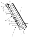
- the perspective view of Figure 1 shows the switching device 1 one Safety bar for arrangement on closing edges of movable devices.
- the Switching device 1 comprises a contact element chain 2, which of a variety of Contact elements 2a, 2b, ising, 2x, 2y is formed. These contact elements are along the Safety bar lined up linearly.
- Each of the contact elements 2a, 2b, Vietnamese, 2x, 2y has an electrically conductive core. This electrically conductive area each Contact element is on both sides with the adjacent contact element 2b; 2a; ........., 2y; 2x electrically connected.
- the contact elements are in an idle state lined up coaxially with one another and form a core over the electrically conductive core areas electrically conductive connection to the adjacent contact element and thus via the entire security bar.
- the sleeve-shaped hose pieces 13a, 13b, . «, 13x, 13y each overlap the end areas of two adjacent contact elements 2a, 2b; 2x, 2x and press the contact zones on the front of the contact elements up to today.
- the electrical connection between neighboring contact elements With external pressure on the safety bar, the electrical connection between neighboring contact elements at least locally solved. The resulting interruption the electrical connection along the safety bar is then not by one here shown evaluation unit registered to thereby, for example, the contact of the Register safety bar with an obstacle.
- the switching device 1 is not in one in FIG. 1 for reasons of better illustration elastic hose shown introduced.
- the front openings of this elastic Hoses are each sealed moisture-tight with closure elements 3, 5.
- closure elements 3, 5 have a cable duct for leading out a contact cable 12 from the inside of the hose.
- the cables 12 are each on one Side with the first contact element 2a or the last contact element 2y electrical connected and connected to the evaluation unit on the other side.
- the end region of the switching device 1 is closer in a sectional drawing in FIG. 2 shown.
- the first contact element 2a is shown there.
- This has an electrical conductive metal core 16 and an insulating plastic sheath 18. That in the Representation of Figure 2 left end of the metal core 16 is with the front contact zone of the metal core of the adjacent contact element 2b (no longer shown in FIG. 2) electrically connected and to the right in the illustration of Figure 2 end of Metal core 16, the contact cable 12 is soldered.
- Figure 2 is also the elastic Hose 4 shown, in which the contact element chain 2 is inserted. The front opening the hose 4 is closed moisture-tight by a closure element 5.
- the Closure element 5 comprises a cup-shaped plug 7, the wall 9 in engages the interior of the hose 4 and the pot bottom 14 of the front opening the hose 4 closes.
- the pot bottom 14 of the sealing plug 7 is one Cable bushing 8 is provided to the contact cable 12 from the inside of the hose to lead outside.
- the closure element 5 further comprises a spacer 6, which between the Sealing plug 7 and the first contact element 2a is arranged.
- a spacer 6 which between the Sealing plug 7 and the first contact element 2a is arranged.
- the illustrated embodiment is the spacer 6 from a first cylindrical Spacer sleeve 6a and in this regard displaceable in the longitudinal direction of the safety bar arranged second cylindrical spacer sleeve 6b formed.
- the length of the spacer 6 is continuously adjustable between a minimum position and a maximum position by the two spacer sleeves 6a, 6b can be moved against each other.
- the length of the spacer 6 can thus be adjusted when installing the safety bar the total length of the safety bar according to local conditions adjust.
- the inner spacer sleeve 6b facing the first contact element 2a is at one of them End firmly connected to the first contact element 2a.
- the other spacer sleeve 6a has an inner diameter which is slightly larger than the outer diameter of the inner spacer 6b, so that this spacer 6a as an outer spacer over the inner Spacer sleeve 6b can be pushed.
- a bore 15 is provided into which a grub screw can be screwed, whereby the relative position between the spacer sleeves 6a and 6b can be fixed.
- the wall 9 of the sealing plug 7 has several side by side on the outside and parallel grooves 16. On the one hand, these grooves 16 cause the plug 7 can be easily pushed into the hose opening and on the other hand, they seal the hose opening to the outside against moisture according to Art a labyrinth seal.
- a clamping device is used to fasten the sealing plug 7 in the hose opening 11 provided.
- this is Clamping device 11 from a hose clamp 11 encompassing the hose end 4a educated.
- This hose clamp 11 causes the hose end 4a firmly against the Wall 9 of the plug 7 is pressed.
- a rubber end cap 16 is additionally provided, which is placed over the plug 7 and on the outer jacket of the hose 4th is glued or vulcanized.
- a roller shutter or an automatic vehicle door is the elastic one Hose 4 on a (not shown in Figure 2) elastic profile extension on one Aluminum profile 17 attached.
- the aluminum profile 17 is also shown in Figure 1. This aluminum profile 17 is closed at the closing edge of the movable device Fasten.
- the adjustable length of the spacer 6 makes it possible to have a modular construction Manufacture safety bar of any length.
- the distance between the end of the first Contact element 2a or the last contact element 2y and the end of the hose 4th can be bridged by the spacer 6, the one to be bridged Distance is infinitely adjustable by the inner spacer sleeve 6b and the outer spacer sleeve 6a are shifted against each other.
- the inner one Spacer sleeve 6b with an external thread and the outer spacer sleeve 6a with one corresponding internal thread can then by screwing or unscrewing the inner spacer sleeve 6b from the outer Spacer sleeve 6a take place.
- the position of the inner spacer sleeve 6a with the outer spacer sleeve 6b interchanged, i.e. the outer spacer sleeve 6a is with the first Contact element 2a connected and the inner spacer sleeve 6b engages in the interior of the pot-shaped sealing plug 7 a.
- the Lock nut 7 for fixing the mutual position of the inner with respect to the outer Spacer sleeve can be formed by the plug 7, which has an internal thread for this purpose has, which corresponds to the external thread of the inner spacer sleeve 6b.
- Closure element 15 is preferably firmly connected to the first contact element 2a.
- the Closure element 5, the first contact element 2a and the contact cable 12 thus form one Unit, which when assembling the safety bar in a final step to close the front opening of the tube 4 are inserted into this can.
- Both front ends of the hose 4 are preferably of identical construction Closure elements 3, 5 completed.
- the closure element 5, comprising the first or last contact element 2a, the Spacer 6 and the plug 7, can also be used with safety strips come in which the elastic bias of the contact elements by an im End region of the hose 4 arranged spring is effected.
- the spring that creates the preload is here between the first or last contact element 2a and the sealing plug 7 arranged.
- the spacer 6 according to the present invention is preferred here within the spring to bridge the distance between the end of the first or last one Contact element 2a and the pot base 14 of the sealing plug 7 and within the Coil spring arranged.
- This embodiment of the present invention has the additional effect that the strength of the spring tension and thus the preload between the individual contact elements by extending or shortening the length of the adaptable spacer 6 can be adjusted.
- FIGS. 3A-3H show different embodiments of the spacer 6 shown.
- the spacers shown in Figures 3A to 3E each have an outer cylindrical spacer sleeve 6a and an inner spacer sleeve 6b which can be inserted therein.
- the embodiment shown in FIG. 3A has the outer spacing sleeve 6a Internal thread 19 and the inner spacer sleeve 6b a corresponding one Male thread 20 on.
- the length of the spacer 6 is by screwing the inner Spacer sleeve 6b continuously adjustable in the outer spacer sleeve 6a.
- the spacers 6a and 6b instead of a thread corresponding locking elements 21, 22.
- the spacers 6a and 6b are here Engagement of these locking elements 21, 22 is slidable.
- the one shown in Figure 3C The exemplary embodiment of the spacer 6 essentially corresponds to that in FIG. 2 illustrated exemplary embodiment, with the difference that the inner spacer sleeve 6b several bores 23 spaced apart in the longitudinal direction of the sleeve Has cylinder jacket. In these holes one is through the hole 15 in the outer Spacer 6 engaging grub screw screwed, whereby the two spacers 6a and 6b are fastened to one another and their position relative to one another.
- Grub screw can also fix the two spacer sleeves 6a and 6b with a pin 24 can be realized through the bore 15 in the cylinder jacket of the outer spacer sleeve and is inserted through a bore 23 of the inner spacer sleeve, as shown in Figure 3D.
- a ball 25 can be used as a further alternative for fixing the two spacer sleeves 6a and 6b are used, which also through the bore 15 and in one of the bores 23rd is introduced as shown in Figure 3E.
- the spacer 6 from a single cylindrical sleeve 6c This either has several, in the longitudinal direction the sleeve has predetermined breaking points 26 arranged one behind the other (FIG. 3F) or it consists of a plurality of nested rings 6d, as in the embodiments of FIG Figures 3G and 3H shown (especially in the right representation of this).
- the disks 6d bite to match each other on their end faces corresponding to each other Plug elements 27 on.
- the embodiment shown in Figure 3H differs from the embodiment shown in Figure 3G in that the disks 6d on The outer circumference is slit to add the length of a disc 6d if necessary to reduce or supplement.
Landscapes
- Clamps And Clips (AREA)
- Operating, Guiding And Securing Of Roll- Type Closing Members (AREA)
- Materials For Medical Uses (AREA)
- Pipe Accessories (AREA)
- Connector Housings Or Holding Contact Members (AREA)
Abstract
Description
- Figur 1
- Perspektivische Darstellung der Schalteinrichtung einer Sicherheitsleiste;
- Figur 2
- Querschnitt durch den Endbereich einer Sicherheitsleiste.
- Figuren 3A - 3H
- Verschiede Ausführungsformen von Distanzstücken zur Verwendung in einer Sicherheitsleiste, wie in Figur 2 dargestellt.
Claims (18)
- Sicherheitsleiste zur Anordnung an Schließkanten bewegbarer Einrichtungen,dadurch gekennzeichnet, daß zumindest das eine Verschlußelement (5) ein in seiner Länge anpassbares Distanzstück (6) umfaßt.mit einer Schalteinrichtung (1), die eine Kontaktelementekette (2) aufweist, welche von einer Vielzahl von Kontaktelementen (2a, 2b, ..., 2x, 2y) gebildet ist, die längs der Sicherheitsleiste so aneinandergereiht sind, dass jedes Kontaktelement (2a; 2b; 2x; 2y) in einem Ruhezustand nach beiden Seiten mit dem jeweils benachbarten Kontaktelement (2b; 2a; 2y; 2x) elektrisch leitend verbunden ist und die elektrische Verbindung zwischen benachbarten Kontaktelementen zumindest lokal bei Verbiegen der Schalteinrichtung (1) durch äußeren Druck auf die Sicherheitsleiste gelöst wird,mit einem elastischen Schlauch (4), in dem die Kontaktelementekette (2) angeordnet ist, undmit Verschlußelementen (3, 5) zum Verschließen der stirnseitigen Enden des Schlauches (4), wobei zumindest eines der Verschlußelemente (5) eine Einrichtung zur Durchfiihrung des elektrischen Kontakts des ersten bzw. letzten Kontaktelements der Kontaktelementekette (2) aufweist,
- Sicherheitsleiste nach Anspruch 1, dadurch gekennzeichnet, dass das Verschlußelement (5) einen mit einer Kabeldurchfiihrung (8) versehenen Verschlußstopfen (7) aufweist, der in den Innenraum des Schlauches (4) eingreift und das stirnseitige Ende des Schlauches verschließt.
- Sicherheitsleiste nach Anspruch 2, dadurch gekennzeichnet, dass das Distanzstück (6) zwischen dem Verschlußstopfen (7) und dem ersten bzw. letzten Kontaktelement (2a) angeordnet ist.
- Sicherheitsleiste nach einem der Ansprüche 1 bis 3, dadurch gekennzeichnet, dass das Distanzstück (6) von einer ersten Distanzhülse (6a) und einer diesbezüglich in Längsrichtung der Sicherheitsleiste verschieblich angeordneten zweiten Distanzhülse (6b) gebildet ist, wodurch die Länge des Distanzstücks (6) stufenlos zwischen einer Minimalstellung und einer Maximalstellung eingestellt werden kann.
- Sicherheitsleiste nach einem der Ansprüche 1 bis 4, dadurch gekennzeichnet, dass das Distanzstück von einer ersten Distanzhülse (6a) mit Innengewinde und einer zweiten Distanzhülse (6b) mit dazu korrespondierendem Außengewinde gebildet ist.
- Sicherheitsleiste nach Anspruch 5, dadurch gekennzeichnet, dass die Lage der ersten Distanzhülse (6a) bezüglich der zweiten Distanzhülse (6b) mittels einer Kontermutter fixierbar ist.
- Sicherheitsleiste nach Anspruch 6, dadurch gekennzeichnet, dass die Kontermutter von dem mit einem Innengewinde versehenen Verschlußstopfen (7) gebildet wird.
- Sicherheitsleiste nach Anspruch 5, dadurch gekennzeichnet, dass die Lage der ersten Distanzhülse (6a) bezüglich der zweiten Distanzhülse (6b) mittels einer Madenschraube fixierbar ist.
- Sicherheitsleiste nach einem der Ansprüche 2 bis 8, dadurch gekennzeichnet, dass der Verschlußstopfen (7) topfförmig ausgebildet ist und mit seiner Wandung (9) in die stirnseitige Öffnung des Schlauches ragt.
- Sicherheitsleiste nach Anspruch 9, dadurch gekennzeichnet, dass das der Kontaktelementekette (2) abgewandte Ende des Distanzstücks (6) in den Innenraum (10) des topfförmigen Verschlußstopfens (7) ragt.
- Sicherheitsleiste nach einem der Ansprüche 1 bis 10, dadurch gekennzeichnet, dass das Verschlußelement (5) mittels einer Klemmeinrichtung (11) in der Schlauchöffnung fixiert ist.
- Sicherheitsleiste nach Anspruch 11, dadurch gekennzeichnet, dass die Klemmeinrichtung von einer das Schlauchende (4a) umgreifende Schlauchklemme (11) gebildet ist.
- Sicherheitsleiste nach einem der Ansprüche 2 bis 12, dadurch gekennzeichnet, dass am ersten bzw. letzten Kontaktelement (2a) ein Kabel (12) angebracht ist, welches durch das Distanzstück (6) verläuft und durch die Kabeldurchführung (8) vom Innern des Schlauches (4) nach außen geführt ist.
- Sicherheitsleiste nach einem der voranstehenden Ansprüche, dadurch gekennzeichnet, dass das der Kontaktelementekette (2) zugewandte Ende des Distanzstücks (6) fest mit dem ersten bzw. letzten Kontaktelement (2a) verbunden ist.
- Sicherheitsleiste nach einem der voranstehenden Ansprüche, dadurch gekennzeichnet, dass das Verschlußelement (5) und das erste bzw. letzte Kontaktelement (2a) fest miteinander verbunden sind und so eine Baueinheit bilden, welche beim Zusammenbau der Sicherheitsleiste in einem den Zusammenbau abschließenden Schritt in die stirnseitige Öffnung des Schlauches (4) eingefügt werden kann.
- Sicherheitsleiste nach einem der voranstehenden Ansprüche, dadurch gekennzeichnet, dass an beiden stirnseitigen Enden des Schlauches ein baugleiches Verschlußelement (3, 5) vorgesehen ist.
- Sicherheitsleiste nach einem der voran stehenden Ansprüche, dadurch gekennzeichnet, dass das Distanzstück (6) aus mehreren, ineinanderschiebbaren Distanzhülsen (6a, 6b) zusammengesetzt ist.
- Sicherheitsleiste nach einem der voran stehenden Ansprüche, dadurch gekennzeichnet, dass das Distanzstück (6) aus einer Distanzhülse (6) mit mehreren, in Längsrichtung der Hülse hintereinander angeordneten Sollbruchstellen (26) besteht.
Applications Claiming Priority (2)
| Application Number | Priority Date | Filing Date | Title |
|---|---|---|---|
| DE20302605U | 2003-02-17 | ||
| DE20302605U DE20302605U1 (de) | 2003-02-17 | 2003-02-17 | Sicherheitsleiste |
Publications (3)
| Publication Number | Publication Date |
|---|---|
| EP1447511A2 true EP1447511A2 (de) | 2004-08-18 |
| EP1447511A3 EP1447511A3 (de) | 2008-12-10 |
| EP1447511B1 EP1447511B1 (de) | 2010-07-07 |
Family
ID=32668180
Family Applications (1)
| Application Number | Title | Priority Date | Filing Date |
|---|---|---|---|
| EP04001793A Expired - Lifetime EP1447511B1 (de) | 2003-02-17 | 2004-01-28 | Sicherheitsleiste |
Country Status (3)
| Country | Link |
|---|---|
| EP (1) | EP1447511B1 (de) |
| AT (1) | ATE473342T1 (de) |
| DE (2) | DE20302605U1 (de) |
Cited By (1)
| Publication number | Priority date | Publication date | Assignee | Title |
|---|---|---|---|---|
| DE102005040947B4 (de) * | 2005-08-30 | 2007-07-26 | Iht-Innovative Hebe Technik Gmbh | Signalgebende Schaltleiste für Sicherheitseinrichtungen |
Families Citing this family (2)
| Publication number | Priority date | Publication date | Assignee | Title |
|---|---|---|---|---|
| US8493081B2 (en) | 2009-12-08 | 2013-07-23 | Magna Closures Inc. | Wide activation angle pinch sensor section and sensor hook-on attachment principle |
| US9234979B2 (en) | 2009-12-08 | 2016-01-12 | Magna Closures Inc. | Wide activation angle pinch sensor section |
Family Cites Families (4)
| Publication number | Priority date | Publication date | Assignee | Title |
|---|---|---|---|---|
| DE19647721A1 (de) * | 1996-11-19 | 1998-05-20 | Wampfler Ag | Schließkantensicherheitsleiste |
| DE19647720B4 (de) * | 1996-11-19 | 2004-05-13 | Wampfler Aktiengesellschaft | Schließkantensicherheitsleiste |
| DE19937731C1 (de) * | 1999-06-24 | 2000-11-02 | Andre Haake | Schließkanten-Sicherung |
| EP1063380B1 (de) * | 1999-06-24 | 2008-07-09 | André Haake | Schliesskantensicherung |
-
2003
- 2003-02-17 DE DE20302605U patent/DE20302605U1/de not_active Expired - Lifetime
-
2004
- 2004-01-28 DE DE502004011350T patent/DE502004011350D1/de not_active Expired - Lifetime
- 2004-01-28 EP EP04001793A patent/EP1447511B1/de not_active Expired - Lifetime
- 2004-01-28 AT AT04001793T patent/ATE473342T1/de not_active IP Right Cessation
Cited By (1)
| Publication number | Priority date | Publication date | Assignee | Title |
|---|---|---|---|---|
| DE102005040947B4 (de) * | 2005-08-30 | 2007-07-26 | Iht-Innovative Hebe Technik Gmbh | Signalgebende Schaltleiste für Sicherheitseinrichtungen |
Also Published As
| Publication number | Publication date |
|---|---|
| DE20302605U1 (de) | 2004-07-08 |
| DE502004011350D1 (de) | 2010-08-19 |
| ATE473342T1 (de) | 2010-07-15 |
| EP1447511B1 (de) | 2010-07-07 |
| EP1447511A3 (de) | 2008-12-10 |
Similar Documents
| Publication | Publication Date | Title |
|---|---|---|
| EP1238451B1 (de) | Dichtungskörper für längsgeteilte kabelgarnituren | |
| DE112007000798B4 (de) | Spann- oder Führungsschiene mit Verliersicherung für Haltebolzen | |
| DE4309330A1 (de) | Distanzstück für Rohrschellen | |
| EP2848848B1 (de) | Dichtungsvorrichtung | |
| EP0843065A1 (de) | Schliesskantensicherheitsleiste | |
| EP0749179A1 (de) | Schraubklemme | |
| DE3144901A1 (de) | Elektrisch isolierte verbindung zwischen zwei gleichachsig angeordneten, stabfoermigen elementen aus metall | |
| DE3409350A1 (de) | Vorrichtung zum halten eines elektrischen kabels in einem steckergehaeuse | |
| EP2050918B1 (de) | Absenkdichtung mit Durchgangsöffnung | |
| EP0219072B1 (de) | Dichtungskörper für Kabelgarnituren aus thermoplastischem Kunststoff | |
| DE202005009818U1 (de) | Vorrichtung zur Stromübertragung | |
| EP1447511B1 (de) | Sicherheitsleiste | |
| DE102009008934A1 (de) | Elektrische Anschlussklemme, insbesondere Reihenklemme | |
| DE1565977C3 (de) | Elektrischer Vielfachsteckkupplungshalbteil | |
| DE19908657C1 (de) | Vorrichtung zum Abdecken und Abdichten eines Kabeldurchführungsdurchbruches in einer Wand eines Schaltschrankes | |
| DE3502864A1 (de) | Vorrichtung zur stumpfen elektrischen verbindung von stromschienen | |
| EP1740903A2 (de) | Wegmess-vorrichtung | |
| CH689683A5 (de) | Gehaeuse mit einer Vorrichtung zur Kabelzugentlastung. | |
| DE3024038C1 (de) | Anschluss- und Klemmeinrichtung fuer Koaxialkabel | |
| EP0638975A1 (de) | Muffenkopf mit mehreren geteilten Kabeleinführungen | |
| DE29804397U1 (de) | Verbindungsanordnung zweier Bauteil | |
| DE3302677C2 (de) | Hohlraumendverschluß | |
| DE9313011U1 (de) | Zugentlastungsvorrichtung für eine Leitungsführungsanordnung | |
| DE9112701U1 (de) | Feldabstandhalter für Hochspannungs-Freileitungen mit Bündelleitern | |
| DE19509682C1 (de) | Auflaufsicherung |
Legal Events
| Date | Code | Title | Description |
|---|---|---|---|
| PUAI | Public reference made under article 153(3) epc to a published international application that has entered the european phase |
Free format text: ORIGINAL CODE: 0009012 |
|
| AK | Designated contracting states |
Kind code of ref document: A2 Designated state(s): AT BE BG CH CY CZ DE DK EE ES FI FR GB GR HU IE IT LI LU MC NL PT RO SE SI SK TR |
|
| AX | Request for extension of the european patent |
Extension state: AL LT LV MK |
|
| RAP1 | Party data changed (applicant data changed or rights of an application transferred) |
Owner name: MAYSER GMBH & CO. KG |
|
| PUAL | Search report despatched |
Free format text: ORIGINAL CODE: 0009013 |
|
| AK | Designated contracting states |
Kind code of ref document: A3 Designated state(s): AT BE BG CH CY CZ DE DK EE ES FI FR GB GR HU IE IT LI LU MC NL PT RO SE SI SK TR |
|
| AX | Request for extension of the european patent |
Extension state: AL LT LV MK |
|
| 17P | Request for examination filed |
Effective date: 20081224 |
|
| 17Q | First examination report despatched |
Effective date: 20090317 |
|
| AKX | Designation fees paid |
Designated state(s): AT BE BG CH CY CZ DE DK EE ES FI FR GB GR HU IE IT LI LU MC NL PT RO SE SI SK TR |
|
| AXX | Extension fees paid |
Extension state: MK Payment date: 20090610 Extension state: AL Payment date: 20090610 Extension state: LV Payment date: 20090610 Extension state: LT Payment date: 20090610 |
|
| GRAP | Despatch of communication of intention to grant a patent |
Free format text: ORIGINAL CODE: EPIDOSNIGR1 |
|
| GRAS | Grant fee paid |
Free format text: ORIGINAL CODE: EPIDOSNIGR3 |
|
| GRAA | (expected) grant |
Free format text: ORIGINAL CODE: 0009210 |
|
| AK | Designated contracting states |
Kind code of ref document: B1 Designated state(s): AT BE BG CH CY CZ DE DK EE ES FI FR GB GR HU IE IT LI LU MC NL PT RO SE SI SK TR |
|
| AX | Request for extension of the european patent |
Extension state: AL LT LV MK |
|
| REG | Reference to a national code |
Ref country code: GB Ref legal event code: FG4D Free format text: NOT ENGLISH |
|
| REG | Reference to a national code |
Ref country code: CH Ref legal event code: EP |
|
| REG | Reference to a national code |
Ref country code: IE Ref legal event code: FG4D |
|
| REF | Corresponds to: |
Ref document number: 502004011350 Country of ref document: DE Date of ref document: 20100819 Kind code of ref document: P |
|
| REG | Reference to a national code |
Ref country code: NL Ref legal event code: VDEP Effective date: 20100707 |
|
| PG25 | Lapsed in a contracting state [announced via postgrant information from national office to epo] |
Ref country code: SI Free format text: LAPSE BECAUSE OF FAILURE TO SUBMIT A TRANSLATION OF THE DESCRIPTION OR TO PAY THE FEE WITHIN THE PRESCRIBED TIME-LIMIT Effective date: 20100707 |
|
| LTIE | Lt: invalidation of european patent or patent extension |
Effective date: 20100707 |
|
| PG25 | Lapsed in a contracting state [announced via postgrant information from national office to epo] |
Ref country code: FI Free format text: LAPSE BECAUSE OF FAILURE TO SUBMIT A TRANSLATION OF THE DESCRIPTION OR TO PAY THE FEE WITHIN THE PRESCRIBED TIME-LIMIT Effective date: 20100707 Ref country code: NL Free format text: LAPSE BECAUSE OF FAILURE TO SUBMIT A TRANSLATION OF THE DESCRIPTION OR TO PAY THE FEE WITHIN THE PRESCRIBED TIME-LIMIT Effective date: 20100707 |
|
| REG | Reference to a national code |
Ref country code: IE Ref legal event code: FD4D |
|
| PG25 | Lapsed in a contracting state [announced via postgrant information from national office to epo] |
Ref country code: BG Free format text: LAPSE BECAUSE OF FAILURE TO SUBMIT A TRANSLATION OF THE DESCRIPTION OR TO PAY THE FEE WITHIN THE PRESCRIBED TIME-LIMIT Effective date: 20101007 Ref country code: PT Free format text: LAPSE BECAUSE OF FAILURE TO SUBMIT A TRANSLATION OF THE DESCRIPTION OR TO PAY THE FEE WITHIN THE PRESCRIBED TIME-LIMIT Effective date: 20101108 Ref country code: CY Free format text: LAPSE BECAUSE OF FAILURE TO SUBMIT A TRANSLATION OF THE DESCRIPTION OR TO PAY THE FEE WITHIN THE PRESCRIBED TIME-LIMIT Effective date: 20100707 |
|
| PG25 | Lapsed in a contracting state [announced via postgrant information from national office to epo] |
Ref country code: GR Free format text: LAPSE BECAUSE OF FAILURE TO SUBMIT A TRANSLATION OF THE DESCRIPTION OR TO PAY THE FEE WITHIN THE PRESCRIBED TIME-LIMIT Effective date: 20101008 Ref country code: SE Free format text: LAPSE BECAUSE OF FAILURE TO SUBMIT A TRANSLATION OF THE DESCRIPTION OR TO PAY THE FEE WITHIN THE PRESCRIBED TIME-LIMIT Effective date: 20100707 |
|
| PG25 | Lapsed in a contracting state [announced via postgrant information from national office to epo] |
Ref country code: DK Free format text: LAPSE BECAUSE OF FAILURE TO SUBMIT A TRANSLATION OF THE DESCRIPTION OR TO PAY THE FEE WITHIN THE PRESCRIBED TIME-LIMIT Effective date: 20100707 Ref country code: IE Free format text: LAPSE BECAUSE OF FAILURE TO SUBMIT A TRANSLATION OF THE DESCRIPTION OR TO PAY THE FEE WITHIN THE PRESCRIBED TIME-LIMIT Effective date: 20100707 |
|
| PLBE | No opposition filed within time limit |
Free format text: ORIGINAL CODE: 0009261 |
|
| STAA | Information on the status of an ep patent application or granted ep patent |
Free format text: STATUS: NO OPPOSITION FILED WITHIN TIME LIMIT |
|
| PG25 | Lapsed in a contracting state [announced via postgrant information from national office to epo] |
Ref country code: RO Free format text: LAPSE BECAUSE OF FAILURE TO SUBMIT A TRANSLATION OF THE DESCRIPTION OR TO PAY THE FEE WITHIN THE PRESCRIBED TIME-LIMIT Effective date: 20100707 Ref country code: IT Free format text: LAPSE BECAUSE OF FAILURE TO SUBMIT A TRANSLATION OF THE DESCRIPTION OR TO PAY THE FEE WITHIN THE PRESCRIBED TIME-LIMIT Effective date: 20100707 Ref country code: EE Free format text: LAPSE BECAUSE OF FAILURE TO SUBMIT A TRANSLATION OF THE DESCRIPTION OR TO PAY THE FEE WITHIN THE PRESCRIBED TIME-LIMIT Effective date: 20100707 Ref country code: CZ Free format text: LAPSE BECAUSE OF FAILURE TO SUBMIT A TRANSLATION OF THE DESCRIPTION OR TO PAY THE FEE WITHIN THE PRESCRIBED TIME-LIMIT Effective date: 20100707 Ref country code: SK Free format text: LAPSE BECAUSE OF FAILURE TO SUBMIT A TRANSLATION OF THE DESCRIPTION OR TO PAY THE FEE WITHIN THE PRESCRIBED TIME-LIMIT Effective date: 20100707 |
|
| 26N | No opposition filed |
Effective date: 20110408 |
|
| PG25 | Lapsed in a contracting state [announced via postgrant information from national office to epo] |
Ref country code: ES Free format text: LAPSE BECAUSE OF FAILURE TO SUBMIT A TRANSLATION OF THE DESCRIPTION OR TO PAY THE FEE WITHIN THE PRESCRIBED TIME-LIMIT Effective date: 20101018 |
|
| REG | Reference to a national code |
Ref country code: DE Ref legal event code: R097 Ref document number: 502004011350 Country of ref document: DE Effective date: 20110408 |
|
| BERE | Be: lapsed |
Owner name: MAYSER G.M.B.H. & CO. KG Effective date: 20110131 |
|
| PG25 | Lapsed in a contracting state [announced via postgrant information from national office to epo] |
Ref country code: MC Free format text: LAPSE BECAUSE OF NON-PAYMENT OF DUE FEES Effective date: 20110131 |
|
| REG | Reference to a national code |
Ref country code: CH Ref legal event code: PL |
|
| GBPC | Gb: european patent ceased through non-payment of renewal fee |
Effective date: 20110128 |
|
| REG | Reference to a national code |
Ref country code: FR Ref legal event code: ST Effective date: 20110930 |
|
| PG25 | Lapsed in a contracting state [announced via postgrant information from national office to epo] |
Ref country code: CH Free format text: LAPSE BECAUSE OF NON-PAYMENT OF DUE FEES Effective date: 20110131 Ref country code: FR Free format text: LAPSE BECAUSE OF NON-PAYMENT OF DUE FEES Effective date: 20110131 Ref country code: LI Free format text: LAPSE BECAUSE OF NON-PAYMENT OF DUE FEES Effective date: 20110131 |
|
| PG25 | Lapsed in a contracting state [announced via postgrant information from national office to epo] |
Ref country code: BE Free format text: LAPSE BECAUSE OF NON-PAYMENT OF DUE FEES Effective date: 20110131 Ref country code: GB Free format text: LAPSE BECAUSE OF NON-PAYMENT OF DUE FEES Effective date: 20110128 |
|
| REG | Reference to a national code |
Ref country code: AT Ref legal event code: MM01 Ref document number: 473342 Country of ref document: AT Kind code of ref document: T Effective date: 20110128 |
|
| PG25 | Lapsed in a contracting state [announced via postgrant information from national office to epo] |
Ref country code: AT Free format text: LAPSE BECAUSE OF NON-PAYMENT OF DUE FEES Effective date: 20110128 |
|
| PGFP | Annual fee paid to national office [announced via postgrant information from national office to epo] |
Ref country code: DE Payment date: 20130308 Year of fee payment: 10 |
|
| PG25 | Lapsed in a contracting state [announced via postgrant information from national office to epo] |
Ref country code: LU Free format text: LAPSE BECAUSE OF NON-PAYMENT OF DUE FEES Effective date: 20110128 |
|
| PG25 | Lapsed in a contracting state [announced via postgrant information from national office to epo] |
Ref country code: TR Free format text: LAPSE BECAUSE OF FAILURE TO SUBMIT A TRANSLATION OF THE DESCRIPTION OR TO PAY THE FEE WITHIN THE PRESCRIBED TIME-LIMIT Effective date: 20100707 |
|
| PG25 | Lapsed in a contracting state [announced via postgrant information from national office to epo] |
Ref country code: HU Free format text: LAPSE BECAUSE OF FAILURE TO SUBMIT A TRANSLATION OF THE DESCRIPTION OR TO PAY THE FEE WITHIN THE PRESCRIBED TIME-LIMIT Effective date: 20100707 |
|
| REG | Reference to a national code |
Ref country code: DE Ref legal event code: R119 Ref document number: 502004011350 Country of ref document: DE |
|
| PG25 | Lapsed in a contracting state [announced via postgrant information from national office to epo] |
Ref country code: DE Free format text: LAPSE BECAUSE OF NON-PAYMENT OF DUE FEES Effective date: 20140801 |
|
| REG | Reference to a national code |
Ref country code: DE Ref legal event code: R119 Ref document number: 502004011350 Country of ref document: DE Effective date: 20140801 |