EP1447475A2 - Verfahren und Vorrichtung zum Beschichten einer Materialbahn - Google Patents
Verfahren und Vorrichtung zum Beschichten einer Materialbahn Download PDFInfo
- Publication number
- EP1447475A2 EP1447475A2 EP03104816A EP03104816A EP1447475A2 EP 1447475 A2 EP1447475 A2 EP 1447475A2 EP 03104816 A EP03104816 A EP 03104816A EP 03104816 A EP03104816 A EP 03104816A EP 1447475 A2 EP1447475 A2 EP 1447475A2
- Authority
- EP
- European Patent Office
- Prior art keywords
- application medium
- application
- distribution chamber
- medium
- pressure
- Prior art date
- Legal status (The legal status is an assumption and is not a legal conclusion. Google has not performed a legal analysis and makes no representation as to the accuracy of the status listed.)
- Withdrawn
Links
Images
Classifications
-
- D—TEXTILES; PAPER
- D21—PAPER-MAKING; PRODUCTION OF CELLULOSE
- D21H—PULP COMPOSITIONS; PREPARATION THEREOF NOT COVERED BY SUBCLASSES D21C OR D21D; IMPREGNATING OR COATING OF PAPER; TREATMENT OF FINISHED PAPER NOT COVERED BY CLASS B31 OR SUBCLASS D21G; PAPER NOT OTHERWISE PROVIDED FOR
- D21H23/00—Processes or apparatus for adding material to the pulp or to the paper
- D21H23/02—Processes or apparatus for adding material to the pulp or to the paper characterised by the manner in which substances are added
- D21H23/22—Addition to the formed paper
Definitions
- the present invention relates to a method and an apparatus for or coating of a material web on both sides, in particular of paper or cardboard, with a liquid or pasty application medium, in particular aqueous pigment suspension, by applying the application medium a moving surface, which in a direct Application process a surface of the material web and an indirect one Application method is the surface of a transfer element, of which the application medium is transferred to the material web.
- the invention relates in particular a method in which the application medium from a Order medium stock of at least one distribution chamber of an order station fed and from there directly to the underground, where before the output of the order medium to the underground hydrostatic pressure of the application medium by a control device is regulated.
- the present invention also relates more precisely to a device having a Order medium stock, an order station and a control device, which before the delivery of the order medium from the order station to Regulates the hydrostatic pressure of the application medium.
- the control device advantageously works with a storage device together.
- the object is achieved according to a first aspect of the invention by a method of the type mentioned, in which the application medium via an application medium delivery line directly to the at least one distribution chamber is supplied and the pressure of the application medium in the at least one distribution chamber to a predetermined or predeterminable pressure is regulated.
- This chamber becomes the application medium without the interposition of a feed chamber via an application medium delivery line fed.
- Application medium from the distribution chamber directly to the surface output. It has been shown that it is necessary to achieve a good Coating result is sufficient and for certain application processes, such as such as curtain application, is even more advantageous in printing the distribution chamber to be controlled by a control device.
- the one through the The target pressure to be set by the control device can be predefined. However, it can also be advantageous by an operator or the control device itself can be specified, so that changes in the application device itself or in the vicinity of the application device during operation Changes in the target pressure can be taken into account.
- the construction of the application station can be greatly simplified because of pressure control and application medium output the moving underground takes place in a chamber.
- the coating result improved because of the very short control time a change in the pressure in the distribution chamber itself faster than in the prior art on the formation of the application medium layer affects the material web.
- the aforementioned distribution chamber can be any chamber from which medium is dispensed onto a moving surface.
- the distribution chamber can be the application chamber of a short dwell application device his.
- the invention can be particularly preferred
- the process can be used as a curtain application process, making it the at least one distribution chamber is essentially one machine-wide distribution chamber according to the curtain application process working application device in which the application medium, in particular aqueous pigment suspension, in the form of a Moving curtain or veil on the Is delivered underground, the distribution chamber the application medium is supplied directly via an application medium delivery line and the Distribution chamber the application medium through an outlet opening as a curtain or releases veil to the surface.
- curtain application processes it is in fact crucial to apply the application medium in the correct dosage Material web to apply, as a doctoring of the Application medium is undesirable or impossible. This final dosage will achieved with high accuracy by the inventive method.
- curtain order coaters work, compared to other order processes, usually regarding the delivery medium to be delivered in a significantly smaller pressure range. There then even slight absolute pressure fluctuations are comparatively large cause relative changes in the prevailing pressure level is one Regulation of the application medium pressure in the distribution chamber for this Application process particularly effective.
- the pressure control of the application medium pressure in the at least one distribution chamber advantageously enables a very sensitive, sensitive Regulation of the order quantity with very short control times.
- Through long-term Machine operations can change the order relationships, for example by heating machine parts or by wear, which is why the amount actually applied to the material web can be useful Monitor application medium (coat weight).
- Monitor application medium coat weight
- the invention Process the amount of material applied to the web Capture the order medium and, depending on the capture result Amount of from the distribution chamber per unit of time to the underground regulate the order medium.
- the target pressure can be specified by the control device, on which the application medium pressure is adjusted in the distribution chamber.
- the control device comprise a storage device in the corresponding Maps are stored or in which the acquisition values are saved can.
- the regulation by detecting the line weight by means of the at least one the second sensor has a longer controlled system, because the stroke weight sensing sensor, such as a measuring frame, usually on a Machine location is arranged, in which the on the material web applied layer of application medium has already dried to remove any To avoid damage to the application medium layer.
- the Object of the invention also achieved by a method for one or both sides Coating a material web, in particular made of paper or cardboard, with a liquid or pasty application medium, especially aqueous Pigment suspension, by applying the application medium to yourself moving surface, which is a direct application process Surface of the material web and in the case of an indirect application process Surface of a transfer element, from which the application medium the material web is transferred, with which method the application medium from an order medium supply of at least one distribution chamber Order station fed and from there directly to the underground is issued, before the delivery of the order medium to
- the hydrostatic pressure of the application medium through a Control device is controlled, the control device the application medium pressure in the at least one distribution chamber to a predetermined one or specifiable pressure and regulates the amount of applied to the material web Order medium recorded and depending on the recording result the amount of from the distribution chamber per unit of time to the subsurface regulates the delivery medium.
- Application medium is vented or / and filtered before entering the distribution chamber become.
- the application medium is preferably both vented and filtered, to contain gas bubbles and suspended particles as well as others Remove solids so that the application medium is as pure as possible gets onto the material web.
- the control device can, above all, the delivery rate of per time unit of the application medium supplied to the distribution chamber as manipulated variable to change. This can be done in a simple manner, for example Change the performance of an application medium feed pump or / and by a change in a passage cross section of a in the application medium delivery line provided throttle valve happen. This control option can be realized particularly easily, since a feed pump and a Throttle valve usually in an application medium delivery line anyway are provided.
- one from the distribution chamber can be used for pressure control outgoing application medium discharge line may be provided, the pressure of the application medium in the distribution chamber very quickly through a Change in the flow rate of application medium through the application medium discharge line can be regulated.
- the application medium drain line can also be used for further venting of the application medium become.
- the pressure in the distribution chamber is reduced in a particularly short time become.
- the amount of application medium removed can also be at least one in this Variable power pump and / or at least one throttle valve changeable passage cross-section can be provided.
- the change in Performance of the discharge side pump and / or the change in Passage cross section of the outlet-side throttle valve can be used Simplification of the construction of the machine also by Control device are executed.
- This Pressure sensor can be arranged in the application medium delivery line, where it is particularly easy to access for repair or maintenance purposes.
- the pressure sensor should be in the application medium delivery line in the conveying direction after venting has taken place or / and be arranged after filtering has taken place.
- a pressure sensor can be provided in the distribution chamber. To do that In the distribution chamber, the risk of mistake detection should be reduced provided pressure sensor at a distance from the application medium inlet be arranged.
- the drives of rollers and others are often located Elements on one machine side (drive side) and the control panel Operation of the application device on the other side of the machine (Operator side). Usually the color is from one long side of the paper or Cardboard machine fed into the distribution chamber, usually this is the drive side. In such a case, it is particularly favorable to use the pressure sensor to an end region opposite the application medium inlet Distribution chamber should be provided to prevent pressure losses within the distribution chamber capture.
- the amount of application medium applied to the material web can at least one further sensor, preferably in the form of a proven measuring frame, provided and connected to the control device his.
- the control device instead of specifying the target pressure for the first control loop, alternatively or additionally change parameters other than the manipulated variable. It turned out to be proven particularly favorable, at least one rheological parameter of the Change order medium as manipulated variable.
- Control loops one of which uses short-term changes, such as rapid pressure fluctuations or pressure surges, by regulating the Application medium pressure in the distribution chamber and the other control loop long-term changes by changing other parameters, for example regulates the rheological parameters of the application medium.
- the second control loop can control the temperature of the Change the application medium in the distribution chamber as a manipulated variable.
- a manipulated variable usually goes with the increase in temperature a decrease in viscosity as well as a Change other parameters of the order medium, such as the Surface tension, hand in hand.
- the coating result can still be improved, in particular with a curtain application process that the material web after the order of order medium is redirected so that your Direction of movement one component in the machine longitudinal direction and one Has component in the direction of gravity, according to the Redirection, preferably contactless, is redirected again such that their direction of movement one component in the machine longitudinal direction and one Has component against the direction of gravity. Furthermore the required machine length is achieved by repeated bending of the web, when viewed in a machine longitudinal section, within limits held.
- the above object is achieved also solved by a device of the type mentioned, in which the Application station comprises at least one distribution chamber to which one Order medium delivery line directly from the order medium supply is excluded and from the order medium directly to Is delivered underground and their application medium pressure in their Inside is adjustable.
- the foregoing Object of the invention also achieved by a device for one or coating a material web on both sides, in particular from paper or Cardboard, with a liquid or pasty application medium, in particular aqueous pigment suspension, by applying the application medium a moving surface, which with a direct application process a surface of the material web and with an indirect application process is the surface of a transfer element, of which the Application medium is transferred to the material web
- the device comprises: an order medium supply, an order station and one Control device, preferably with a storage device, which Control device before the delivery of the order medium from the Application station to the underground the hydrostatic pressure of the application medium regulates, the order station one according to the curtain order process working order station which is a distribution chamber includes the application medium through an outlet opening in Form of a curtain that moves mainly due to gravity or veil to a surface.
- the object of the invention solved by a device for one or both sides Coating a material web, in particular made of paper or cardboard, with a liquid or pasty application medium, in particular aqueous pigment suspension, by applying the application medium to yourself moving surface, which is a direct application process Surface of the material web and in the case of an indirect application process Surface of a transfer element, from which the application medium the material web is transferred,
- the device comprising: a Order medium supply, an order station and a control device, preferably with a storage device, which control device before Output of the order medium from the order station to the underground regulates hydrostatic pressure of the application medium, the control device is connected to at least one first sensor, which is the application medium pressure detected in the distribution chamber, and with at least a second Sensor is connected, preferably a measuring frame, which the amount of application medium applied to the material web is recorded.
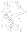
- the present invention will be explained in more detail below with reference to a drawing are explained.
- the drawing shows a schematic section of a Machine for coating a paper or cardboard web on which in An application medium is applied to the curtain coating process.
- a material web 10 made of paper or cardboard is in the direction of Arrow 12 fed to an order station 14.
- the material web 10 is around a first deflecting roller 16 deflected.
- an air interface reducer 18 arranged which carried along by the material web surface 10a Air boundary layer reduced before application.
- the order station 14 is subsequently provided. It refers to an order station operating according to the curtain order process, as they do is known as the "Curtain Coater".
- the order station 14 comprises a partially cylindrical distribution chamber 20 which is formed from a flat wall 20a and one formed from a cylinder sector partially cylindrical wall 20b.
- this distribution chamber 20 which is in Cross machine direction Q essentially over the entire machine width extends, there is a gap at its end 20c facing the material web provided, through which a curtain 22 of application medium 23 in the direction gravity g emerges and onto the surface 10a of the material web 10a the impact point 24 strikes.
- the coated surface 10a of the material web 10 passed a first drying unit 28. Following this Drying unit is the material web 10 to avoid Damage to the still wet coating without contact by such a way called air turn 30 deflected such that after the deflection Movement direction of the material web 10 a movement component in Direction of the machine longitudinal direction L and a movement component against the direction of gravity g. Through these redirections becomes a long drying stretch of the material web without any noteworthy Extension of the machine construction space achieved. Following the redirection through the air turn 30, in which the material web via an air cushion is guided, the material web 10 arrives at a second and third Drying device 32 or 34. Following the drying devices 32 and 34 there is a further deflection by a Deflection roller 36, according to which the direction of movement of the material web 10 in Machine longitudinal direction L takes place.
- the distribution chamber 20 is connected via an application medium delivery line 38 Order medium 23 supplied.
- a pump 40 pumps the application medium from an order medium supply, not shown, to the distribution chamber 20.
- Direction of delivery F after the pump 40 is a ventilation and filter unit 42 provided which contain gas bubbles and solids in the application medium or suspended matter removed.
- a pressure sensor 44 is arranged near the end region 38a near the application station 14, which detects the hydrostatic pressure of the application medium and via a Data line 46 transmits to a control device 48.
- the control device 48 is connected to the pump 40 via a further data line 50 and can change the delivery rate of the pump via this connection. The Change takes place in such a way that the end section 38a Order medium delivery line 38 and thus in the distribution chamber 20 a target or Set target pressure.
- the ventilation and Filter unit 42 subsequently a throttle valve 51 in the application medium delivery line 38 provided and via a data line 53 with the control device 48 connected.
- the control device can thus the passage cross section of the throttle valve change to a desired application medium pressure (Target pressure) in the distribution chamber 20.
- the control device 48 works to store and retrieve stored data Data or maps with a storage unit 49, which in the The illustrated embodiment is part of the control device 48. As well an external storage device can be used.
- control device 48 is connected to a via a data line 54 Measuring frame 52 connected. With the measuring frame 42 that is on the Line weight applied applied to the web of material, d. H. the per unit area amount of application medium applied to the material web. Depending on the control device can determine the detection result by the measuring frame 52 48 increase or decrease the performance of the pump 40 and / or can Control device 48 change the passage cross section of throttle valve 51 or / and the control device 48 can include an admixing device 56 operate which the application medium either a dilution or a Thickener is added to increase the viscosity of the application medium enlarge or reduce. The control of the admixing device 56 by the control device 48 via a data line 58, which the Mixing device 56 and the control device 48 connects.
- control device 48 can be one that is not shown Operate heat exchanger device to control the temperature of the application medium to increase or decrease.
- an application medium drain line 60 At the longitudinal end opposite the application medium inlet Distribution chamber is an application medium drain line 60 to the distribution chamber 20 connected.
- the throttle valve is over one Data line 66 and the pump 64 via a data line 68 with the Control device 48 connected. For reasons of clarity, they are Data lines 66 and 68 not fully marked.
- Both the performance of the pump 64 and the passage cross section of the Throttle valve 62 can be changed by the control device 48.
- the application medium discharge line 60 becomes application medium 23 from the Distribution chamber 20 promoted to the order medium supply. This is one very rapid reduction of the application medium pressure in the distribution chamber 20 possible.
Landscapes
- Application Of Or Painting With Fluid Materials (AREA)
- Coating Apparatus (AREA)
- Paper (AREA)
Abstract
Description
Claims (22)
- Verfahren zum ein- oder beidseitigen Beschichten einer Materialbahn (10), insbesondere aus Papier oder Karton, mit einem flüssigen oder pastösen Auftragsmedium (23), insbesondere wässeriger Pigmentsuspension, durch Auftragen des Auftragsmediums auf einen sich bewegenden Untergrund (10a), welcher bei einem direkten Auftragsverfahren eine Oberfläche (10a) der Materialbahn (10) und bei einem indirekten Auftragsverfahren die Oberfläche eines Übertragselementes ist, von welchem das Auftragsmedium (23) auf die Materialbahn (10) übertragen wird,
bei welchem Verfahren das Auftragsmedium (23) von einem Auftragsmedium-Vorrat wenigstens einer Verteilkammer (20) einer Auftragsstation (14) zugeführt und von dort unmittelbar zu dem Untergrund (10a) hin ausgegeben wird,
wobei vor der Ausgabe des Auftragsmediums (23) zum Untergrund hin der hydrostatische Druck des Auftragsmediums (23) durch eine Regelvorrichtung (48) geregelt wird,
dadurch gekennzeichnet, dass das Auftragsmedium (23) über eine Auftragsmedium-Förderleitung (38) unmittelbar der Verteil kammer (20) zugeführt wird und der Druck des Auftragsmediums (23) in der Verteilkammer (20) auf einen vorgegebenen oder vorgebbaren Druck geregelt wird. - Verfahren nach dem Oberbegriff des Anspruchs 1 oder nach Anspruch 1,
dadurch gekennzeichnet, dass es ein Vorhangsauftragsverfahren ist, bei welchem das Auftragsmedium (23) von der Verteilkammer (20) durch eine Austrittsöffnung (bei 20c) in Form eines sich im Wesentlichen schwerkraftbedingt bewegenden Vorhangs oder Schleiers an den Untergrund abgegeben wird, wobei der Druck des Auftragsmediums (23) in der Verteilkammer (20) auf einen vorgegebenen oder vorgebbaren Druck geregelt wird. - Verfahren nach dem Oberbegriff des Anspruchs 1 oder nach Anspruch 1 oder 2,
dadurch gekennzeichnet, dass die Regelvorrichtung (48) den Auftragsmedium-Druck in der Verteilkammer (20) auf einen vorgegebenen oder vorgebbaren Druck regelt und die Menge an auf die Materialbahn (10) aufgetragenem Auftragsmedium (23) erfasst und in Abhängigkeit von dem Erfassungsergebnis die Menge an von der Verteilkammer (20) pro Zeiteinheit zum Untergrund (10a) hin abgegebenem Auftragsmedium (23) regelt. - Verfahren nach einem der vorhergehenden Ansprüche,
dadurch gekennzeichnet, dass das Auftragsmedium (23) vor dem Eintritt in die Verteilkammer (20) entlüftet oder/und gefiltert wird. - Verfahren nach einem der vorhergehenden Ansprüche,
dadurch gekennzeichnet, dass die Regelvorrichtung (48) die Fördermenge von pro Zeiteinheit der Verteilkammer (20) zugeführtem Auftragsmedium (23) als Stellgröße ändert. - Verfahren nach einem der vorhergehenden Ansprüche,
dadurch gekennzeichnet, dass der Druck des Auftragsmediums (23) in der Verteilkammer (20) durch eine Veränderung der Leistung einer Auftragsmedium-Förderpumpe (40) oder/und durch eine Veränderung eines Durchlassquerschnitts eines in der Auftragsmedium-Förderleitung (38) vorgesehenen Drosselventils (51) geregelt wird. - Verfahren nach einem der vorhergehenden Ansprüche,
dadurch gekennzeichnet, dass eine von der Verteilkammer (20) abgehende Auftragsmedium-Ablassleitung (60) vorgesehen ist, wobei der Druck des Auftragsmediums (23) in der Verteilkammer (20) durch eine Veränderung der Durchflussmenge an Auftragsmedium (23) durch die Auftragsmedium-Ablassleitung (60) geregelt wird. - Verfahren nach einem der vorhergehenden Ansprüche,
dadurch gekennzeichnet, dass der Auftragsmedium-Druck in der Verteilkammer (20) durch wenigstens einen Drucksensor (44) erfasst wird, welcher in der Auftragsmedium-Förderleitung (38), dort bevorzugt in Förderrichtung (F) nach einer erfolgten Entlüftung oder/und Filterung (42), oder/und in der Verteilkammer (20), dort bevorzugt mit Abstand von dem Auftragsmedium-Einlass, besonders bevorzugt an einem dem Auftragsmedium-Einlass gegenüberliegenden Endbereich der Verteilkammer (20), vorgesehen ist. - Verfahren nach einem der vorhergehenden Ansprüche,
dadurch gekennzeichnet, dass von der Verteilkammer (20) genau die pro Zeiteinheit auf die Materialbahn (10) aufzutragende Menge an Auftragsmedium (23) abgegeben wird. - Verfahren nach einem der Ansprüche 3 bis 9, unter Rückbeziehung auf Anspruch 3,
dadurch gekennzeichnet, dass die Regelvorrichtung (48) wenigstens einen rheologischen Parameter des Auftragsmediums (23) als Stellgröße ändert. - Verfahren nach Anspruch 10,
dadurch gekennzeichnet, dass die Regelvorrichtung (48) die Viskosität des Auftragsmediums (23) als den wenigstens einen rheologischen Parameter verändert, etwa durch Beimengung von Verdünnungsoder/und Verdickungsmedien zu dem Auftragsmedium. - Verfahren nach Anspruch 10 oder 11,
dadurch gekennzeichnet, dass die Regelvorrichtung (48) die Temperatur des Auftragsmediums (23) als Stellgröße ändert. - Verfahren nach einem der vorhergehenden Ansprüche,
dadurch gekennzeichnet, dass die Materialbahn (10) nach dem Auftrag von Auftragsmedium (23) derart umgelenkt (bei 26) wird, dass ihre Bewegungsrichtung eine Komponente in Maschinenlängsrichtung (L) und eine Komponente in Richtung der Schwerkraft (g) aufweist, wobei sie nach der Umlenkung, vorzugsweise berührungslos, erneut derart umgelenkt (bei 30) wird, dass ihre Bewegungsrichtung eine Komponente in Maschinenlängsrichtung (L) und eine Komponente entgegen der Richtung der Schwerkraft (g) aufweist. - Vorrichtung zum ein- oder beidseitigen Beschichten einer Materialbahn (10), insbesondere aus Papier oder Karton, mit einem flüssigen oder pastösen Auftragsmedium (23), insbesondere wässeriger Pigmentsuspension, durch Auftragen des Auftragsmediums (23) auf einen sich bewegenden Untergrund (10a), welcher bei einem direkten Auftragsverfahren eine Oberfläche (10a) der Materialbahn (10) und bei einem indirekten Auftragsverfahren die Oberfläche eines Übertragselementes ist, von welchem das Auftragsmedium (23) auf die Materialbahn (10) übertragen wird, vorzugsweise nach einem Verfahren gemäß wenigstens einem der Ansprüche 1 bis 13, wobei die Vorrichtung aufweist:dadurch gekennzeichnet, dass die Auftragsstation (14) wenigstens eine Verteilkammer (20) umfasst, an welche eine Auftragsmedium-Förderleitung (38) von dem Auftragsmedium-Vorrat unmittelbar angeschlossen ist und von welcher aus Auftragsmedium (23) unmittelbar zum Untergrund (10a) hin abgegeben wird und deren Auftragsmedium-Druck in ihrem Inneren regelbar ist.einen Auftragsmedium-Vorrat,eine Auftragsstation (14) sowieeine Regelvorrichtung (48), vorzugsweise mit einer Speichervorrichtung (49), welche Regelvorrichtung (48) vor der Ausgabe des Auftragsmediums (23) von der Auftragsstation (14) zum Untergrund (10a) hin den hydrostatischen Druck des Auftragsmediums (23) regelt,
- Vorrichtung nach dem Oberbegriff des Anspruchs 14 oder nach Anspruch 14,
dadurch gekennzeichnet, dass die Auftragsstation (14) eine nach dem Vorhangsauftragsverfahren arbeitende Auftragsstation (14) ist, welche eine Verteilkammer (20) umfasst, die das Auftragsmedium (23) durch eine Austrittsöffnung (bei 20c) in Form eines sich im Wesentlichen schwerkraftbedingt bewegenden Vorhangs (22) oder Schleiers (14) an einen Untergrund abgibt. - Vorrichtung nach dem Oberbegriff des Anspruchs 14 oder nach Anspruch 14 oder 15,
dadurch gekennzeichnet, dass die Regelvorrichtung (48) mit wenigstens einem ersten Sensor (44) verbunden ist, welcher den Auftragsmedium-Druck in der Verteilkammer (20) erfasst, und mit wenigstens einem zweiten Sensor (52) verbunden ist, vorzugsweise einem Messrahmen (52), welcher die Menge an auf die Materialbahn (10) aufgetragenem Auftragsmedium (23) erfasst. - Vorrichtung nach einem der Ansprüche 14 bis 16,
dadurch gekennzeichnet, dass sie eine Entlüftungs- (42) oder/und eine Filtervorrichtung (42) umfasst, welche das Auftragsmedium (23) vor Eintritt in die Verteilkammer (20) entlüftet oder/und filtert. - Vorrichtung nach einem der Ansprüche 14 bis 17,
dadurch gekennzeichnet, dass eine von der Verteilkammer (20) abgehende Auftragsmedium-Ablassleitung (60) vorgesehen ist, welche vorzugsweise eine Pumpe (64) mit veränderbarer Pumpleistung oder/und ein Drosselventil (62) mit veränderbarem Durchlassquerschnitt umfasst. - Vorrichtung nach einem der Ansprüche 14 bis 18,
dadurch gekennzeichnet, dass sie in einer Auftragsmedium-Förderleitung (38) zur Förderung des Auftragsmediums (23) in die Verteilkammer (20) eine Pumpe (40) mit veränderbarer Pumpleistung oder/und ein Drosselventil (41) mit veränderlichem Durchlassquerschnitt umfasst. - Vorrichtung nach einem der Ansprüche 14 bis 19,
dadurch gekennzeichnet, dass sie einen Drucksensor (44) zur Erfassung des Auftragsmedium-Drucks in der Verteilkammer (20) umfasst, welcher in der Auftragsmedium-Förderleitung (38), dort bevorzugt in Förderrichtung nach einer erfolgten Entlüftung oder/und Filterung, oder/und in der Verteilkammer (20), dort bevorzugt mit Abstand von dem Auftragsmedium-Einlass, besonders bevorzugt an einem dem Auftragsmedium-Einlass gegenüberliegenden Endbereich der Verteilkammer (20), vorgesehen ist. - Vorrichtung nach einem der Ansprüche 16 bis 20, unter Rückbeziehung auf Anspruch 16,
dadurch gekennzeichnet, dass sie eine von der Regelvorrichtung (20) betätigbare Beimengungsvorrichtung (56) zur Beimengung von Verdünnungs- oder/und Verdickungsmedien zu dem Auftragsmedium (23) aufweist. - Vorrichtung nach einem der Ansprüche 16 bis 21, unter Rückbeziehung auf Anspruch 16,
dadurch gekennzeichnet, dass sie eine von der Regelvorrichtung (48) betätigbare Temperaturveränderungsvorrichtung zur Änderung der Temperatur des Auftragsmediums (23) in der Verteilkammer aufweist.
Applications Claiming Priority (2)
| Application Number | Priority Date | Filing Date | Title |
|---|---|---|---|
| DE2002160593 DE10260593A1 (de) | 2002-12-23 | 2002-12-23 | Verfahren und Vorrichtung zum Beschichten einer Materialbahn |
| DE10260593 | 2002-12-23 |
Publications (2)
| Publication Number | Publication Date |
|---|---|
| EP1447475A2 true EP1447475A2 (de) | 2004-08-18 |
| EP1447475A3 EP1447475A3 (de) | 2004-11-17 |
Family
ID=32404192
Family Applications (1)
| Application Number | Title | Priority Date | Filing Date |
|---|---|---|---|
| EP03104816A Withdrawn EP1447475A3 (de) | 2002-12-23 | 2003-12-19 | Verfahren und Vorrichtung zum Beschichten einer Materialbahn |
Country Status (2)
| Country | Link |
|---|---|
| EP (1) | EP1447475A3 (de) |
| DE (2) | DE20221974U1 (de) |
Cited By (1)
| Publication number | Priority date | Publication date | Assignee | Title |
|---|---|---|---|---|
| CN102639254A (zh) * | 2009-11-13 | 2012-08-15 | 福伊特专利有限公司 | Df涂布机 |
Families Citing this family (3)
| Publication number | Priority date | Publication date | Assignee | Title |
|---|---|---|---|---|
| FI117059B (fi) | 2004-09-21 | 2006-05-31 | Metso Paper Inc | Menetelmä ja sovitelma epäpuhtauksien erottelemiseksi päällystysaseman konekierrosta |
| FI121122B (fi) * | 2006-01-26 | 2010-07-15 | Metso Paper Inc | Menetelmä ja laitteisto kuiturainan päällystykseen käytettävän päällystysaineen käsittelemiseksi ja syöttämiseksi päällystyslaitteelle |
| DE102009007649B4 (de) * | 2008-02-07 | 2017-10-26 | Valmet Technologies, Inc. | Verfahren und Anordnung zur Reduzierung von Bahnabrissen bei der Herstellung von Papier oder Karton |
Family Cites Families (8)
| Publication number | Priority date | Publication date | Assignee | Title |
|---|---|---|---|---|
| JP3165043B2 (ja) * | 1996-09-05 | 2001-05-14 | 東レエンジニアリング株式会社 | 液体塗布装置 |
| DE19755625A1 (de) * | 1997-12-15 | 1999-07-01 | Jagenberg Papiertech Gmbh | Schlitzdüse zum Beschichten von Materialbahnen, insbesondere Papier- oder Kartonbahnen mit Pigmentstreichfarbe |
| DE19803240A1 (de) * | 1998-01-28 | 1999-07-29 | Voith Sulzer Papiertech Patent | Farbvorhang-Auftragsvorrichtung |
| DE19903559B4 (de) * | 1998-01-30 | 2004-02-26 | Mitsubishi Paper Mills Limited | Verfahren und Apparatur zur Vorhangbeschichtung |
| FI104577B (fi) | 1998-05-25 | 2000-02-29 | Valmet Raisio Oy | Menetelmä ja sovitelma käsittelyaineen syöttämiseksi paperi- tai kartonkiradan käsittelylaitteelle |
| DE10012344A1 (de) * | 2000-03-14 | 2001-09-20 | Voith Paper Patent Gmbh | Vorhang-Auftragsverfahren |
| DE10057731A1 (de) * | 2000-11-22 | 2002-06-06 | Voith Paper Patent Gmbh | Vorhang-Auftragsvorrichtung |
| DE10057733A1 (de) * | 2000-11-22 | 2002-05-23 | Voith Paper Patent Gmbh | Vorhang-Auftragsvorrichtung |
-
2002
- 2002-12-23 DE DE20221974U patent/DE20221974U1/de not_active Expired - Lifetime
- 2002-12-23 DE DE2002160593 patent/DE10260593A1/de not_active Withdrawn
-
2003
- 2003-12-19 EP EP03104816A patent/EP1447475A3/de not_active Withdrawn
Cited By (1)
| Publication number | Priority date | Publication date | Assignee | Title |
|---|---|---|---|---|
| CN102639254A (zh) * | 2009-11-13 | 2012-08-15 | 福伊特专利有限公司 | Df涂布机 |
Also Published As
| Publication number | Publication date |
|---|---|
| DE20221974U1 (de) | 2009-12-31 |
| EP1447475A3 (de) | 2004-11-17 |
| DE10260593A1 (de) | 2004-07-01 |
Similar Documents
| Publication | Publication Date | Title |
|---|---|---|
| EP0969147B1 (de) | Vorrichtung und Verfahren zum Auftragen eines flüssigen oder pastösen Mediums auf eine laufende Materialbahn | |
| DE69728984T2 (de) | Verfahren und vorrichtung zum auftragen eines materials auf ein bahnförmiges substrat | |
| EP2727652B1 (de) | Beleimung von materialstreifen der tabak verarbeitenden industrie | |
| EP3401022B1 (de) | Förderer, beschichtungseinrichtung mit einem förderer und betriebsverfahren dafür | |
| DE4131131C2 (de) | Vorrichtung zum Auftragen von Streichfarbe auf eine Faserstoffbahn | |
| EP2493690B1 (de) | Druckeinstellvorrichtung eines kammerrakelsystems | |
| EP1253241B1 (de) | Verfahren und Vorrichtung zum Einbringen von Merkmalsstoffen in eine Papierbahn | |
| WO1995030049A1 (de) | Verfahren und vorrichtung zum herstellen beidseitig gestrichener papierbahnen | |
| DE19605183A1 (de) | Verfahren zur Regelung des Strichgewichtes-Querprofiles | |
| DE10136270A1 (de) | Durchbiegungseinstellwalze | |
| AT392989B (de) | Stoffauflauf fuer papiermaschinen | |
| DE69717317T2 (de) | Verfahren und vorrichtung zum auftragen einer beschichtung auf eine bei hoher geschwindigkeit laufende papierbahn | |
| DE20221974U1 (de) | Vorrichtung zum Beschichten einer Materialbahn | |
| DE60216531T2 (de) | Auftragsvorrichtung und Verfahren zur Herstellung von beschichtetem Papier | |
| DE19731947A1 (de) | Verfahren zum Steuern bzw. Regeln einer Vorrichtung zum Auftragen eines flüssigen oder pastösen Mediums auf eine Gegenfläche | |
| DE112004001664T5 (de) | Papier-/Kartonbahnstreichvorrichtung | |
| DE10057731A1 (de) | Vorhang-Auftragsvorrichtung | |
| DE112004001570T5 (de) | Anordnung in einem Düsenbalken für eine Vorrichtung zum Beschichten einer Faserbahn | |
| DE602004001344T2 (de) | Verfahren zum zuführen eines behandlungsmittels in eine auftragungsvorrichtung | |
| DE69527024T2 (de) | Verfahren und Aufbau zur Überwachung des Beschichtungsprofils in Beschichtungsvorrichtungen, die auf einem Auftrag mit kurzer Wartezeit basieren | |
| DE10355967A1 (de) | Vorrichtung zum Aufbringen einer Flüssigkeitsmischung auf einen bahnförmigen Bedruckstoff | |
| EP2067531A2 (de) | Randführung | |
| DE102010044030A1 (de) | Vorhangauftragswerk | |
| DE19858653A1 (de) | Verfahren und Vorrichtung zum Auftragen eines flüssigen oder pastösen Auftragsmediums auf einen laufenden Untergrund | |
| EP1760195B1 (de) | Vorrichtung und Verfahren zum Beschichten einer Faserstoffbahn |
Legal Events
| Date | Code | Title | Description |
|---|---|---|---|
| PUAI | Public reference made under article 153(3) epc to a published international application that has entered the european phase |
Free format text: ORIGINAL CODE: 0009012 |
|
| AK | Designated contracting states |
Kind code of ref document: A2 Designated state(s): AT BE BG CH CY CZ DE DK EE ES FI FR GB GR HU IE IT LI LU MC NL PT RO SE SI SK TR |
|
| AX | Request for extension of the european patent |
Extension state: AL LT LV MK |
|
| PUAL | Search report despatched |
Free format text: ORIGINAL CODE: 0009013 |
|
| AK | Designated contracting states |
Kind code of ref document: A3 Designated state(s): AT BE BG CH CY CZ DE DK EE ES FI FR GB GR HU IE IT LI LU MC NL PT RO SE SI SK TR |
|
| AX | Request for extension of the european patent |
Extension state: AL LT LV MK |
|
| 17P | Request for examination filed |
Effective date: 20050517 |
|
| AKX | Designation fees paid |
Designated state(s): AT BE BG CH CY CZ DE DK EE ES FI FR GB GR HU IE IT LI LU MC NL PT RO SE SI SK TR |
|
| RAP1 | Party data changed (applicant data changed or rights of an application transferred) |
Owner name: VOITH PATENT GMBH |
|
| STAA | Information on the status of an ep patent application or granted ep patent |
Free format text: STATUS: THE APPLICATION IS DEEMED TO BE WITHDRAWN |
|
| 18D | Application deemed to be withdrawn |
Effective date: 20061012 |