EP1447387A1 - Vorrichtung zum Herstellen einer Glasschmelze - Google Patents
Vorrichtung zum Herstellen einer Glasschmelze Download PDFInfo
- Publication number
- EP1447387A1 EP1447387A1 EP04010546A EP04010546A EP1447387A1 EP 1447387 A1 EP1447387 A1 EP 1447387A1 EP 04010546 A EP04010546 A EP 04010546A EP 04010546 A EP04010546 A EP 04010546A EP 1447387 A1 EP1447387 A1 EP 1447387A1
- Authority
- EP
- European Patent Office
- Prior art keywords
- glass
- cover
- melting
- melt
- melting tank
- Prior art date
- Legal status (The legal status is an assumption and is not a legal conclusion. Google has not performed a legal analysis and makes no representation as to the accuracy of the status listed.)
- Withdrawn
Links
Images


Classifications
-
- C—CHEMISTRY; METALLURGY
- C03—GLASS; MINERAL OR SLAG WOOL
- C03B—MANUFACTURE, SHAPING, OR SUPPLEMENTARY PROCESSES
- C03B5/00—Melting in furnaces; Furnaces so far as specially adapted for glass manufacture
- C03B5/02—Melting in furnaces; Furnaces so far as specially adapted for glass manufacture in electric furnaces, e.g. by dielectric heating
- C03B5/027—Melting in furnaces; Furnaces so far as specially adapted for glass manufacture in electric furnaces, e.g. by dielectric heating by passing an electric current between electrodes immersed in the glass bath, i.e. by direct resistance heating
- C03B5/0275—Shaft furnaces
-
- C—CHEMISTRY; METALLURGY
- C03—GLASS; MINERAL OR SLAG WOOL
- C03B—MANUFACTURE, SHAPING, OR SUPPLEMENTARY PROCESSES
- C03B5/00—Melting in furnaces; Furnaces so far as specially adapted for glass manufacture
- C03B5/02—Melting in furnaces; Furnaces so far as specially adapted for glass manufacture in electric furnaces, e.g. by dielectric heating
- C03B5/027—Melting in furnaces; Furnaces so far as specially adapted for glass manufacture in electric furnaces, e.g. by dielectric heating by passing an electric current between electrodes immersed in the glass bath, i.e. by direct resistance heating
- C03B5/03—Tank furnaces
- C03B5/031—Cold top tank furnaces
-
- C—CHEMISTRY; METALLURGY
- C03—GLASS; MINERAL OR SLAG WOOL
- C03B—MANUFACTURE, SHAPING, OR SUPPLEMENTARY PROCESSES
- C03B5/00—Melting in furnaces; Furnaces so far as specially adapted for glass manufacture
- C03B5/16—Special features of the melting process; Auxiliary means specially adapted for glass-melting furnaces
- C03B5/20—Bridges, shoes, throats, or other devices for withholding dirt, foam, or batch
Definitions
- the invention relates to a device for producing a glass melt a batch.
- a device for producing a glass melt is mostly of rectangular plan. It has peripheral walls and a floor on. It is also equipped with an electric heater. Here you can several heating circuits can also be provided. The heating takes place via electrodes. There is a direct current flow through the conductive glass melt through instead.
- the drain channel is completely open towards the weld pool.
- the channel runs in essentially horizontal, and thus in a parallel to the melt level Level. It has an outlet which is located in the area of one of the side walls of the Melting tank is located.
- the glass melt In operation, the glass melt is always covered by a cold batch cover covered.
- the tub is therefore also called a "cold-top melting tub" designated. It is ensured that the mirror of the glass melt is always is covered by batch.
- a so-called glow strip released At the edges of the melting surface, i.e. to the Peripheral walls, however, is usually a so-called glow strip released, which serves to degas the melt. This can be done through a Inserting machine can be controlled.
- the one lying on the glass melt Batch story has an insulating effect. Isn't the batch story closed, so there is heat radiation, which energy loss means. This means that batches are always adjusted accordingly.
- DE 1 080 740 B describes a device for producing a glass melt from batches, the heated melting tank having an exhaust duct, its inlet opening in a region of the bottom of the melting tank is arranged.
- the culvert is located under the bottom of the Melting tank and has an outlet opening in the area of a peripheral wall.
- the discharge duct is at least at two corners directly on the wall of the Tub brought up.
- US 4,410,997 A describes an apparatus for producing a glass melt from batch.
- the heated melting tank has an exhaust duct that runs in a central area of the tub floor. There is none Cover provided.
- DE 29 17 386 A also describes a melting tank with an exhaust duct, that starts from the bottom of the tub. A cover of the culvert is not provided here.
- the invention has for its object a melting tank of the described Type in such a way that a complete melting of the batch as well as a complete refining of the glass is guaranteed, and that not the lowest batches and blistered glass in the flue get and along with the rest of the glass flow through it Enter the outlet opening.
- the mentioned exhaust duct which is open towards the molten pool, is located outside the main area of the electrical heating.
- the flow velocities that occur there are comparatively low.
- the glass of the glass melt can protrude in certain areas.
- a predominantly downward flow builds up in the area of the peripheral wall in which the outlet is also located.
- the inventors propose the following four approaches before, which can be used individually or in combination.
- the first way is as follows: The culvert is covered over part of its extent. All that remains is an opening that is in the area of the effect of the heating circuits. In general, this inlet opening in the discharge channel will be arranged in a central area of the trough bottom. The trough bottom is thus - apart from the entry opening into the fume cupboard - the cover of the fume cupboard at the same time. You could also say that the canal is largely covered.
- the cover extends from the area of its outlet opening to a central area of the trough bottom, but expediently, however, at least up to one tenth of the distance between two mutually opposite peripheral walls of the melting trough.
- refractory materials metallic or non-metallic
- Refractory metals are available here such as molybdenum or tungsten and their alloys.
- the second solution is as follows: A cover is provided, for example from the material from which the tub is made. The cover covers part of the mirror of the melting surface. The melting area is thus reduced. This leads to a favorable influence on the glass flow, since the heat dissipation via the cover is less than via the batch cover, and since a thermal barrier is thus built up below the cover. This prevents batches that have not melted completely or glass that has not been completely refined from being able to get directly into the removal flow. In this way, batches that have not been completely melted remain longer in the melting tank and are completely melted and refined. The result is the same as the first solution.
- the third solution is one in the area of the duct Provide additional heating, in the area above the outlet of the Exhaust duct, where the glass flow leaves the tub.
- Additional heating consists in building a thermal barrier that prevents will that not completely melted batch or not completely refined glass can get directly into the extraction flow.
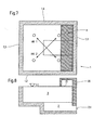
- the fourth approach is to use the area above the outlet of the Exhaust duct, where the glass flow leaves the tub, a heated vault (for example by a burner) and no mixture in this area appeal. There is thus a bare glass surface through which Energy from the heated vault can enter the glass bath. Like in second and third solution path, a thermal barrier is thus built up, which prevents batches that have not melted completely or glass that has not been completely refined can get directly into the sampling flow. All four solutions thus completely melt the Batch and sufficient refining of the glass melt guaranteed. It will prevent any batch particles that are not complete melted, or blistered glass get into the fume cupboard and thus leave the melting tank with the flow of glass.
- the device according to the invention shown in FIGS. 1 and 2 comprises a melting tank 1. This is rectangular. It has four peripheral walls 1.1 to 1.4, also a floor 1.5.
- the tub is heated electrically, for example by two heating circuits HK1 and HC2. These heating circuits couple the necessary heating energy into the one to be generated Glass melt 3 a.
- the drain channel 2 There is a drainage channel 2 under the floor.
- the drain channel 2 also has a bottom 2.1. The bottom runs horizontally in the illustrated embodiment.
- the top of the channel is covered by a cover 2.2.
- the cover 2.2 is approximately at the level of the floor 1.5. It connects to the peripheral wall 1.1 of the melting tank 1 and extends up to about a third of the distance between the peripheral walls 1.1 and 1.3. Due to the design and arrangement of the cover 2.2 relative to the floor 1.5, an opening 2.3 remains. This is the entry opening through which glass melt reaches the discharge channel 2 from the space enclosed by the actual melting tank 1.
- the drain channel 2 has an outlet opening 2.4. As can be seen, this is located in the region of the peripheral wall 1.1 of the melting tank 1.
- the energy of the heating circuits covers most of the melt pool 3. There convection occurs, which also affects the remote angle of the Melting furnace interior captured. So only glass gets in completely melted and refined form through the inlet opening 2.3 in the Discharge channel 2, and thus through its outlet opening 2.4 Further processing.
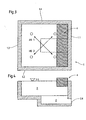
- a melting tank 1 with its peripheral walls 1.1, 1.2, 1.3 and 1.4. Also two heating circuits HK1 and HK2 are assigned, the heating energy in couple the glass melt 3 to be produced.
- a cover 4 is provided.
- the cover consists of stones made of refractory material.
- the cover extends over the entire length of the peripheral wall 1.1 between the two peripheral walls 1.2 and 1.4. They are partially immersed in the melt pool 3, and in some cases they protrude from the melt pool beyond its level 3.1.
- the cover 4 can also have a different shape. It does not have to extend over the entire peripheral wall 1.1. It can also extend along other circumferential walls, so that the area of the mirror 3.1 is reduced even more than shown here.
- the cover 4 does not necessarily have to be immersed in the weld pool 3. One touch with the mirror 3.1 is sufficient. There could even be a certain distance between the lower edge of the cover and the mirror 3.1.
- FIGS. 7 and 8 show a device similar to that according to FIG. 3 and 4. However, a heated vault 20 is provided here. This ensures that a bare glass surface 21 remains. In this area there is no Batch inserted.
Landscapes
- Chemical & Material Sciences (AREA)
- Engineering & Computer Science (AREA)
- Materials Engineering (AREA)
- Organic Chemistry (AREA)
- Chemical Kinetics & Catalysis (AREA)
- Electrochemistry (AREA)
- Glass Melting And Manufacturing (AREA)
Abstract
Description
Der genannte, gegen das Schmelzbad hin offene Abzugskanal befindet sich ausserhalb des Hauptbereiches der elektrischen Heizung. Dort sind die auftretenden Strömungsgeschwindigkeiten vergleichsweise gering. Hierbei kann das Glas der Glasschmelze in gewissen Bereichen abstehen. Im Bereich der Umfangswand, in der sich auch der Auslass befindet, baut sich eine überwiegend nach unten gerichtete Strömung auf. Durch diese Strömung ist es möglich, dass nicht vollständig aufgeschmolzenes Gemenge oder nicht vollständig geläutertes Glas direkt in die Entnahmeströmung im Abzugskanal eintritt und die genannten nachteiligen Folgen hervorruft.
Der Abzugskanal wird auf einem Teil seiner Erstreckung abgedeckt. Es verbleibt lediglich eine Öffnung, die sich im Bereich der Wirkung der Heizkreise befindet. Im allgemeinen wird diese Eintrittsöffnung in den Abzugskanal in einem zentralen Bereich des Wannenbodens angeordnet sein. Der Wannenboden ist somit - bis auf die Eintrittsöffnung in den Abzugskanal - gleichzeitig die Abdeckung des Abzugskanales. Man könnte auch sagen, dass der Kanal weitgehend abgedeckt ist. Die Abdeckung erstreckt sich vom Bereich seiner Austrittsöffnung zu einem zentralen Bereich des Wannenbodens hin, zweckmäßigerweise jedoch mindestens bis zu einem Zehntel des Abstandes zwischen zwei einander gegenüberliegenden Umfangswänden der Schmelzwanne.
Es wird eine Abdeckung vorgesehen, beispielsweise aus jenem Material, aus dem auch die Wanne besteht. Die Abdeckung deckt einen Teil des Spiegels der Schmelzfläche ab. Die Schmelzfläche wird somit verkleinert. Dies führt zu einer günstigen Beeinflussung der Glasströmung, da die Wärmeabfuhr über die Abdeckung geringer ist, als über die Gemengedecke, und da sich somit unterhalb der Abdeckung eine thermische Barriere aufbaut. Dadurch wird verhindert, dass nicht vollständig aufgeschmolzenes Gemenge oder nicht vollständig geläutertes Glas direkt in die Entnahmeströmung gelangen kann. Auf diese Weise verbleiben nicht vollständig aufgeschmolzene Gemengeanteile länger in der Schmelzwanne und werden vollständig aufgeschmolzen und geläutert. Das Ergebnis ist dasselbe, wie bei dem ersten Lösungsweg.
- Figur 1
- zeigt eine Vorrichtung zum Herstellen einer Glasschmelze gemäß der Erfindung in Draufsicht, und zwar gemäß dem ersten Lösungsweg.
- Figur 2
- zeigt die Vorrichtung zum Herstellen einer Glasschmelze von Fig. 1 in einem Vertikalschnitt.
- Figur 3
- zeigt eine weitere Vorrichtung zum Herstellen einer Glasschmelze, und zwar gemäß dem zweiten Lösungsweg.
- Figur 4
- zeigt den Gegenstand von Figur 3 in einem Vertikalschnitt.
- Figur 5
- zeigt eine weitere Vorrichtung zum Herstellen einer Glasschmelze gemäß dem dritten Lösungsweg.
- Figur 6
- zeigt den Gegenstand von Figur 5 in einem Vertikalschnitt.
- Figur 7
- zeigt eine Vorrichtung zum Herstellen einer Glasschmelze gemäß dem vierten Lösungsweg.
- Figur 8
- zeigt den Gegenstand von Figur 7 in einem Vertikalschnitt.
Der Abzugskanal 2 hat ebenfalls einen Boden 2.1. Der Boden verläuft im dargestellten Ausführungsbeispiel horizontal. Der Kanal ist an seiner Oberseite durch eine Abdeckung 2.2 abgedeckt. Wie man sieht, befindet sich die Abdeckung 2.2 etwa auf der Höhe des Bodens 1.5. Sie schließt an die Umfangswand 1.1 der Schmelzwanne 1 an und erstreckt sich bis etwa zu einem Drittel des Abstandes zwischen den Umfangswänden 1.1 und 1.3. Aufgrund der Gestaltung und Anordnung der Abdeckung 2.2 relativ zum Boden 1.5 verbleibt eine Öffnung 2.3. Dies ist die Eintrittsöffnung, durch welche Glasschmelze aus dem von der eigentlichen Schmelzwanne 1 umschlossenen Raum in den Abzugskanal 2 gelangt. Der Abzugskanal 2 weist eine Austrittsöffnung 2.4 auf. Wie man sieht, befindet sich diese im Bereich der Umfangswand 1.1 der Schmelzwanne 1.
Die Abdeckung 4 kann aber auch eine andere Form haben. Sie muß sich nicht über die ganze Umfangswand 1.1 erstrecken. Sie kann sich auch an anderen der Umfangswände entlang erstrecken, so dass die Fläche des Spiegels 3.1 noch stärker verkleinert wird, als hier dargestellt. Außerdem muß die Abdeckung 4 nicht unbedingt in das Schmelzbad 3 eintauchen. Eine Berührung mit dem Spiegel 3.1 reicht aus. Es könnte sogar ein gewisser Abstand zwischen der Unterkante der Abdeckung und dem Spiegel 3.1 verbleiben.
- Glasflussrichtung: 5 bis 50 % der Wannenlänge, vorzugsweise 5 bis 25 %
- quer zur Glasflussrichtung: mindestens der Bereich über dem Kanal muß beeinflusst werden, bis zur gesamten Wannenbreite
- Höhe: 10 bis 100 % der Schmelzbeckenhöhe, ausgehend von der theoretischen Glaslinie, vorzugsweise 10 bis 50 %
- Elektroden: Stab, Platte, Block, Kalotte
- Einbau: Seitenelektroden (Seitenwände oder Rückwand), Top-Elektroden, Boden-Elektroden (wobei Höhe 10 bis 100 % Glasstand, vorzugsweise 50 bis 80 %)
- bei Stabelektroden: auch mit einem Winkel ungleich 90° zur Wand.
Claims (4)
- Vorrichtung zum Herstellen einer Glasschmelze aus Gemenge;
- 1.1
- mit einer Schmelzwanne (1), die Umfangswände (1.1 - 1.4) und einen Boden (1.5) aufweist;
- 1.2
- mit einem Abzugskanal (2), der sich unter dem Boden (1.5) der Schmelzwanne (1) befindet und der über eine Eintrittsöffnung (2.3) mit dem Schmelzbad (3) in leitender Verbindung steht und im Bereich einer Umfangswand (1.1) der Schmelzwanne (1) eine Austrittsöffnung (2.4) für die fertige Schmelze aufweist;
- 1.3
- mit wenigstens einer Heizeinrichtung zum Beheizen des Schmelzbades (3); gekennzeichnet durch die folgenden Merkmale:
- 1.4
- es ist eine Abdeckung (4) vorgesehen, die einen Teil des Spiegels (3.1) des Schmelzbades (3) abdeckt.
- Vorrichtung nach Anspruch 1, dadurch gekennzeichnet, dass sich die Abdeckung (4) über Randbereiche des Spiegels (3.1) des Schmelzbades (3) erstreckt.
- Vorrichtung nach einem der Ansprüche 1 oder 2, dadurch gekennzeichnet, dass sich die Abdeckung (4) mindestens über jenen Teil der Umfangswand (1) erstreckt, der sich im Bereich der Austrittsöffnung (2.4) des Abzugskanales (2) befindet.
- Vorrichtung nach einem der Ansprüche 1 bis 3, dadurch gekennzeichnet, dass die Schmelzwanne (1) rechteckig ist.
Applications Claiming Priority (3)
| Application Number | Priority Date | Filing Date | Title |
|---|---|---|---|
| DE10016872A DE10016872C1 (de) | 2000-04-05 | 2000-04-05 | Vorrichtung zum Herstellen einer Glasschmelze |
| DE10016872 | 2000-04-05 | ||
| EP01933780A EP1240110A2 (de) | 2000-04-05 | 2001-03-30 | Vorrichtung zum Herstellen einer Glasschmelze |
Related Parent Applications (1)
| Application Number | Title | Priority Date | Filing Date |
|---|---|---|---|
| EP01933780A Division EP1240110A2 (de) | 2000-04-05 | 2001-03-30 | Vorrichtung zum Herstellen einer Glasschmelze |
Publications (1)
| Publication Number | Publication Date |
|---|---|
| EP1447387A1 true EP1447387A1 (de) | 2004-08-18 |
Family
ID=7637635
Family Applications (4)
| Application Number | Title | Priority Date | Filing Date |
|---|---|---|---|
| EP01933780A Withdrawn EP1240110A2 (de) | 2000-04-05 | 2001-03-30 | Vorrichtung zum Herstellen einer Glasschmelze |
| EP04010547A Withdrawn EP1443027A3 (de) | 2000-04-05 | 2001-03-30 | Vorrichtung zum Herstellen einer Glasschmelze |
| EP04010546A Withdrawn EP1447387A1 (de) | 2000-04-05 | 2001-03-30 | Vorrichtung zum Herstellen einer Glasschmelze |
| EP04010548A Withdrawn EP1445241A1 (de) | 2000-04-05 | 2001-03-30 | Vorrichtung zum Herstellen einer Glasschmelze |
Family Applications Before (2)
| Application Number | Title | Priority Date | Filing Date |
|---|---|---|---|
| EP01933780A Withdrawn EP1240110A2 (de) | 2000-04-05 | 2001-03-30 | Vorrichtung zum Herstellen einer Glasschmelze |
| EP04010547A Withdrawn EP1443027A3 (de) | 2000-04-05 | 2001-03-30 | Vorrichtung zum Herstellen einer Glasschmelze |
Family Applications After (1)
| Application Number | Title | Priority Date | Filing Date |
|---|---|---|---|
| EP04010548A Withdrawn EP1445241A1 (de) | 2000-04-05 | 2001-03-30 | Vorrichtung zum Herstellen einer Glasschmelze |
Country Status (7)
| Country | Link |
|---|---|
| US (1) | US6735237B2 (de) |
| EP (4) | EP1240110A2 (de) |
| JP (1) | JP2003530292A (de) |
| AU (1) | AU6017101A (de) |
| CA (1) | CA2372362A1 (de) |
| DE (1) | DE10016872C1 (de) |
| WO (1) | WO2001077034A2 (de) |
Families Citing this family (4)
| Publication number | Priority date | Publication date | Assignee | Title |
|---|---|---|---|---|
| EP1557399A3 (de) * | 2001-08-20 | 2005-10-26 | Schott AG | Verfahren und Vorrichtung zum Herstellen einer Glasschmelze |
| DE102008038283B4 (de) | 2008-08-18 | 2012-03-15 | Schott Ag | Vorrichtung zur Herstellung einer Glasschmelze aus einem Gemenge und Verfahren zur Herstellung eines Glaskörpers |
| US12497316B2 (en) | 2020-08-14 | 2025-12-16 | Owens-Brockway Glass Container Inc. | Cast cullet-based layer on wall panel for a melter |
| US11912608B2 (en) | 2019-10-01 | 2024-02-27 | Owens-Brockway Glass Container Inc. | Glass manufacturing |
Citations (4)
| Publication number | Priority date | Publication date | Assignee | Title |
|---|---|---|---|---|
| US1657106A (en) * | 1927-07-15 | 1928-01-24 | William K Brownlee | Replaceable floating bridge part for glass furnaces |
| US3755606A (en) * | 1972-10-02 | 1973-08-28 | Corning Glass Works | Apparatus for melting thermoplastic material |
| US4388721A (en) * | 1981-08-03 | 1983-06-14 | Owens-Corning Fiberglas Corporation | Throat upwell baffle |
| EP0128494A2 (de) * | 1983-06-07 | 1984-12-19 | Aug. Horn Söhne Inh. Helmut Horn KG | Universal-Glasschmelzofen |
Family Cites Families (22)
| Publication number | Priority date | Publication date | Assignee | Title |
|---|---|---|---|---|
| GB627863A (en) * | 1946-10-01 | 1949-08-17 | Walter Raymond Schlehr | Improvements in and relating to the conditioning of material, especially glass, for the drawing therefrom of fibres |
| US2902524A (en) * | 1955-10-26 | 1959-09-01 | Stratabar Process Company | Method and apparatus for producing molten silicates |
| DE1080740B (de) * | 1957-04-15 | 1960-04-28 | Owens Illinois Glass Co | Vorrichtung zur gleichfoermigen elektrischen Beheizung von Glas |
| US2919297A (en) * | 1957-04-18 | 1959-12-29 | Owens Illinois Glass Co | Means of controlling electric currents in a furnace forehearth |
| LU47767A1 (de) * | 1965-01-12 | 1966-01-12 | ||
| US3520979A (en) * | 1968-02-26 | 1970-07-21 | Penelectro Ltd | Electrode circuit for hex electric furnace |
| JPS4632676B1 (de) * | 1968-05-21 | 1971-09-23 | ||
| DE2333544A1 (de) * | 1972-07-20 | 1974-01-31 | Corning Glass Works | Schmelzwanne |
| US4029887A (en) * | 1976-04-27 | 1977-06-14 | Corning Glass Works | Electrically heated outlet system |
| SU785234A1 (ru) * | 1978-01-20 | 1980-02-17 | За витель С А Н И Е 7S5234 (И) | Электрическа стекловаренна печь |
| US4161617A (en) * | 1978-05-01 | 1979-07-17 | General Electric Company | Method and apparatus for electrically melting glass |
| US4149022A (en) | 1978-05-01 | 1979-04-10 | General Electric Company | Power control system for electrically melting glass |
| SU785235A1 (ru) * | 1978-11-09 | 1980-12-17 | За витель К. М. Татевос н | Электрическа стекловаренна печь |
| CA1189555A (en) * | 1981-03-16 | 1985-06-25 | Corning Glass Works | Apparatus and method of conditioning and conveying thermoplastic material |
| SU967968A1 (ru) * | 1981-04-30 | 1982-10-23 | за вители | Электрическа стекловаренна печь |
| SU1011562A1 (ru) * | 1981-05-14 | 1983-04-15 | Tatevosyan Karen M | Электрическа стекловаренна печь |
| US4410997A (en) * | 1981-05-27 | 1983-10-18 | Teco/Elemelt Ltd. | Furnaces for the melting of glass |
| US4426217A (en) * | 1982-05-17 | 1984-01-17 | Owens-Corning Fiberglas Corporation | Electric melting of solidified glass in melting units |
| DE3375009D1 (en) * | 1983-09-29 | 1988-02-04 | Owens Corning Fiberglass Corp | Electrical melting of solidified glass in melting units |
| US4737966A (en) * | 1987-01-12 | 1988-04-12 | Corning Glass Works | Electric melter for high electrical resistivity glass materials |
| FR2619560B1 (fr) * | 1987-08-18 | 1992-10-30 | Saint Gobain Vitrage | Procede et dispositif d'elaboration de verre fondu |
| JPH11343124A (ja) * | 1998-05-29 | 1999-12-14 | Central Glass Co Ltd | ガラスの溶融装置 |
-
2000
- 2000-04-05 DE DE10016872A patent/DE10016872C1/de not_active Expired - Fee Related
-
2001
- 2001-03-30 EP EP01933780A patent/EP1240110A2/de not_active Withdrawn
- 2001-03-30 EP EP04010547A patent/EP1443027A3/de not_active Withdrawn
- 2001-03-30 JP JP2001575515A patent/JP2003530292A/ja active Pending
- 2001-03-30 EP EP04010546A patent/EP1447387A1/de not_active Withdrawn
- 2001-03-30 AU AU60171/01A patent/AU6017101A/en not_active Abandoned
- 2001-03-30 EP EP04010548A patent/EP1445241A1/de not_active Withdrawn
- 2001-03-30 US US10/009,929 patent/US6735237B2/en not_active Expired - Lifetime
- 2001-03-30 WO PCT/EP2001/003656 patent/WO2001077034A2/de not_active Ceased
- 2001-03-30 CA CA002372362A patent/CA2372362A1/en not_active Abandoned
Patent Citations (4)
| Publication number | Priority date | Publication date | Assignee | Title |
|---|---|---|---|---|
| US1657106A (en) * | 1927-07-15 | 1928-01-24 | William K Brownlee | Replaceable floating bridge part for glass furnaces |
| US3755606A (en) * | 1972-10-02 | 1973-08-28 | Corning Glass Works | Apparatus for melting thermoplastic material |
| US4388721A (en) * | 1981-08-03 | 1983-06-14 | Owens-Corning Fiberglas Corporation | Throat upwell baffle |
| EP0128494A2 (de) * | 1983-06-07 | 1984-12-19 | Aug. Horn Söhne Inh. Helmut Horn KG | Universal-Glasschmelzofen |
Also Published As
| Publication number | Publication date |
|---|---|
| WO2001077034A3 (de) | 2002-06-20 |
| EP1240110A2 (de) | 2002-09-18 |
| US20020159497A1 (en) | 2002-10-31 |
| WO2001077034A2 (de) | 2001-10-18 |
| EP1443027A2 (de) | 2004-08-04 |
| JP2003530292A (ja) | 2003-10-14 |
| EP1445241A1 (de) | 2004-08-11 |
| US6735237B2 (en) | 2004-05-11 |
| CA2372362A1 (en) | 2001-10-18 |
| EP1443027A3 (de) | 2004-08-11 |
| DE10016872C1 (de) | 2001-10-31 |
| AU6017101A (en) | 2001-10-23 |
Similar Documents
| Publication | Publication Date | Title |
|---|---|---|
| DE102010048297B4 (de) | Vorrichtung zum Läutern einer anorganischen nichtmetallischen Schmelze und Verfahren zur Herstellung eines Glases und/oder einer Glaskeramik | |
| DE19815326C2 (de) | Glasschmelzofen mit Brennern für fossile Brennstoffe und mit inneren Strahlungsschutzwänden | |
| DE69413096T2 (de) | Verfahren und Vorrichtung zum Schmelzen von Glas | |
| EP1313672B1 (de) | Verfahren und vorrichtung zum läutern von glas | |
| DE19924521C2 (de) | Verfahren zum Schmelzen von Glas | |
| EP1285886A2 (de) | Verfahren und Vorrichtung zum Herstellen einer Glasschmelze | |
| DE2631220C2 (de) | Schmelzofen zum Einschmelzen von radioaktiven Stoffen in Glas | |
| DE10244807B4 (de) | Verfahren und Vorrichtung zum schnellen Einschmelzen insbesondere hochreiner aggressiver und hochschmelzender Gläser | |
| EP0086858A1 (de) | Verfahren zum Schmelzen von Glas mit Hilfe von elektrischer Energie und Ofen zur Durchführung dieses Verfahrens | |
| DE4015785C2 (de) | ||
| EP3553034B1 (de) | Verfahren zur herstellung von glasprodukten sowie hierzu geeignete vorrichtung | |
| DE2914728A1 (de) | Glasspinnvorrichtung | |
| DE10016872C1 (de) | Vorrichtung zum Herstellen einer Glasschmelze | |
| DE3828280C2 (de) | Elektrischer Schmelzofen zur Verfestigung von hochgradig radioaktivem Abfall in Glas | |
| DE3022091A1 (de) | Verfahren und vorrichtung zur herstellung von blaeschenfreiem erschmolzenen glas | |
| DE1596446A1 (de) | Verfahren zum Raffinieren geschmolzenen Glases und Ofen zur Ausfuehrung dieses Verfahrens | |
| EP0410338B1 (de) | Schmelzaggregat zum Herstellen von Glas | |
| DE102004006619B4 (de) | Vorrichtung zum Bereitstellen und Verfahren zum Beheizen einer Glasschmelze | |
| EP0118580A1 (de) | Elektrisch beheizter Schmelzofen für aggressive Mineralstoffe mit steiler Viskositätskurve | |
| EP0128494B1 (de) | Universal-Glasschmelzofen | |
| DE69114549T2 (de) | Verfahren und Vorrichtung zum Schmelzen von Rohstoffen. | |
| DE69708240T2 (de) | Verfahren und Vorrichtung zum Abliefern eines überfangenen Glasstrangs | |
| DE19939784C1 (de) | HF-Wall in einer technischen Wanne | |
| DE3418292A1 (de) | Elektrodenanordnung | |
| DE2347298A1 (de) | Elektrischer schmelzofen fuer glasund keramikmassen |
Legal Events
| Date | Code | Title | Description |
|---|---|---|---|
| PUAI | Public reference made under article 153(3) epc to a published international application that has entered the european phase |
Free format text: ORIGINAL CODE: 0009012 |
|
| 17P | Request for examination filed |
Effective date: 20040504 |
|
| AC | Divisional application: reference to earlier application |
Ref document number: 1240110 Country of ref document: EP Kind code of ref document: P |
|
| AK | Designated contracting states |
Kind code of ref document: A1 Designated state(s): AT BE CH CY DE DK ES FI FR GB GR IE IT LI LU MC NL PT SE TR |
|
| RIN1 | Information on inventor provided before grant (corrected) |
Inventor name: KARETTA, FRANK, DR. Inventor name: OTT, FRANZ Inventor name: DUCH, KLAUS-DIETER, DR. Inventor name: BREITFELDER, SIEGFRIED |
|
| RAP1 | Party data changed (applicant data changed or rights of an application transferred) |
Owner name: SCHOTT AG |
|
| AKX | Designation fees paid |
Designated state(s): AT BE CH CY DE DK ES FI FR GB GR IE IT LI LU MC NL PT SE TR |
|
| STAA | Information on the status of an ep patent application or granted ep patent |
Free format text: STATUS: THE APPLICATION IS DEEMED TO BE WITHDRAWN |
|
| 18D | Application deemed to be withdrawn |
Effective date: 20060126 |