EP1446900B1 - Infrarot (ir) übertragungseinrichtung - Google Patents
Infrarot (ir) übertragungseinrichtung Download PDFInfo
- Publication number
- EP1446900B1 EP1446900B1 EP02791583A EP02791583A EP1446900B1 EP 1446900 B1 EP1446900 B1 EP 1446900B1 EP 02791583 A EP02791583 A EP 02791583A EP 02791583 A EP02791583 A EP 02791583A EP 1446900 B1 EP1446900 B1 EP 1446900B1
- Authority
- EP
- European Patent Office
- Prior art keywords
- transmission device
- segment
- lens
- lens element
- transmitter
- Prior art date
- Legal status (The legal status is an assumption and is not a legal conclusion. Google has not performed a legal analysis and makes no representation as to the accuracy of the status listed.)
- Expired - Lifetime
Links
- 230000005540 biological transmission Effects 0.000 title claims abstract description 49
- 230000005855 radiation Effects 0.000 claims description 8
- 239000011521 glass Substances 0.000 claims description 4
- 229920003229 poly(methyl methacrylate) Polymers 0.000 claims description 3
- 239000004417 polycarbonate Substances 0.000 claims description 3
- 229920000515 polycarbonate Polymers 0.000 claims description 3
- 239000004926 polymethyl methacrylate Substances 0.000 claims description 3
- 238000005516 engineering process Methods 0.000 description 9
- 238000004891 communication Methods 0.000 description 7
- 238000004519 manufacturing process Methods 0.000 description 7
- 230000003287 optical effect Effects 0.000 description 6
- 230000008054 signal transmission Effects 0.000 description 4
- 230000009286 beneficial effect Effects 0.000 description 3
- 239000000975 dye Substances 0.000 description 3
- 238000004049 embossing Methods 0.000 description 3
- 238000001746 injection moulding Methods 0.000 description 3
- 239000000463 material Substances 0.000 description 3
- 238000000034 method Methods 0.000 description 3
- 239000000243 solution Substances 0.000 description 3
- 238000012546 transfer Methods 0.000 description 3
- NIXOWILDQLNWCW-UHFFFAOYSA-N acrylic acid group Chemical group C(C=C)(=O)O NIXOWILDQLNWCW-UHFFFAOYSA-N 0.000 description 2
- 238000012937 correction Methods 0.000 description 2
- 238000013461 design Methods 0.000 description 2
- 238000010586 diagram Methods 0.000 description 2
- 230000000694 effects Effects 0.000 description 2
- 238000001914 filtration Methods 0.000 description 2
- 238000010348 incorporation Methods 0.000 description 2
- 229920003023 plastic Polymers 0.000 description 2
- 238000011144 upstream manufacturing Methods 0.000 description 2
- 101150012579 ADSL gene Proteins 0.000 description 1
- 102100020775 Adenylosuccinate lyase Human genes 0.000 description 1
- 108700040193 Adenylosuccinate lyases Proteins 0.000 description 1
- 241001465754 Metazoa Species 0.000 description 1
- 230000004075 alteration Effects 0.000 description 1
- 230000004888 barrier function Effects 0.000 description 1
- 230000002457 bidirectional effect Effects 0.000 description 1
- 230000003139 buffering effect Effects 0.000 description 1
- 239000003990 capacitor Substances 0.000 description 1
- 238000009826 distribution Methods 0.000 description 1
- 230000007613 environmental effect Effects 0.000 description 1
- 239000003822 epoxy resin Substances 0.000 description 1
- RGNPBRKPHBKNKX-UHFFFAOYSA-N hexaflumuron Chemical compound C1=C(Cl)C(OC(F)(F)C(F)F)=C(Cl)C=C1NC(=O)NC(=O)C1=C(F)C=CC=C1F RGNPBRKPHBKNKX-UHFFFAOYSA-N 0.000 description 1
- 238000003384 imaging method Methods 0.000 description 1
- 238000002347 injection Methods 0.000 description 1
- 239000007924 injection Substances 0.000 description 1
- 230000002452 interceptive effect Effects 0.000 description 1
- 239000000990 laser dye Substances 0.000 description 1
- 239000004033 plastic Substances 0.000 description 1
- 229920005668 polycarbonate resin Polymers 0.000 description 1
- 239000004431 polycarbonate resin Substances 0.000 description 1
- 229920000647 polyepoxide Polymers 0.000 description 1
- 238000003825 pressing Methods 0.000 description 1
- 238000012552 review Methods 0.000 description 1
- 230000035945 sensitivity Effects 0.000 description 1
Images



Classifications
-
- H—ELECTRICITY
- H04—ELECTRIC COMMUNICATION TECHNIQUE
- H04B—TRANSMISSION
- H04B10/00—Transmission systems employing electromagnetic waves other than radio-waves, e.g. infrared, visible or ultraviolet light, or employing corpuscular radiation, e.g. quantum communication
- H04B10/11—Arrangements specific to free-space transmission, i.e. transmission through air or vacuum
- H04B10/114—Indoor or close-range type systems
-
- H—ELECTRICITY
- H04—ELECTRIC COMMUNICATION TECHNIQUE
- H04B—TRANSMISSION
- H04B10/00—Transmission systems employing electromagnetic waves other than radio-waves, e.g. infrared, visible or ultraviolet light, or employing corpuscular radiation, e.g. quantum communication
- H04B10/11—Arrangements specific to free-space transmission, i.e. transmission through air or vacuum
- H04B10/112—Line-of-sight transmission over an extended range
- H04B10/1123—Bidirectional transmission
- H04B10/1127—Bidirectional transmission using two distinct parallel optical paths
-
- H—ELECTRICITY
- H04—ELECTRIC COMMUNICATION TECHNIQUE
- H04B—TRANSMISSION
- H04B10/00—Transmission systems employing electromagnetic waves other than radio-waves, e.g. infrared, visible or ultraviolet light, or employing corpuscular radiation, e.g. quantum communication
- H04B10/50—Transmitters
Definitions
- the invention relates to an infrared (IR) transmission device in a housing arranged IR transmit and -Empfangs instituten according to the introductory part of claim 1.
- IR infrared
- Such an infrared transmission device is known from EP 413 948 A.
- Infrared transmission equipment is quite general, for example, in remote controls for consumer electronic devices, such as televisions, video recorders and stereos, but also known for electronic toll systems. Communication with help however, infrared signals are usually only possible over short distances, for example in the area of Dedicated Short Range Communication (DSRC) communication with limited ranges of usually less than 10 m.
- DSRC Dedicated Short Range Communication
- Applicant's non-prepublished application AT 77/2001 is a selective one wireless communication device has been proposed, with the ranges up to 100 or 200 m are possible, with here queries of so-called.
- OBU On Board Unit
- an infrared transmission device of the above specified type the signal transmission over greater distances, depending after execution over several hundred meters to over 1000 m, allows and so to Use in optical "Last Mile" solutions is the most cost-effective and therefore is also widely applicable and which provides sufficiently large transmission bandwidths as well enables data transmission with active error correction.
- the invention provides an infrared transmission device, as defined in claim 1, above.
- a common, multi-segmented Lens element upstream of the infrared elements in which each infrared element a own lens segment of the common lens element is assigned.
- the invention provides a widely applicable, extremely cost-effective infrared solution in particular for the "last mile" - signal transmission, wherein by the specified Lens element in conjunction with the behind it in particular in a larger number provided IR transmit and receive elements and a transmission over larger Distances, up to 1000 m and more, is possible, so the suitability for Participant connections is given. Due to the infrared transmission technology is included a transfer rate of 10 to over 100 Mbit / s possible, that is about more than 10 times Transfer rate compared to ADSL systems or more than 100 times the capacity compared to ISDN systems. There is also a data connection to the Networks commonly used by network operators, such as e.g. ATM, SONET or else LAN networks, e.g. Ethernet.
- the infrared transmission technology also allows active error correction and redundancy procedures as they are to supply sensitive subscriber stations are absolutely necessary; furthermore, it is a remote administration the transmission device possible (via a so-called. "Q-Interface").
- the transmission device With the common multi-segment lens element can be simple and inexpensive manufactured, assembled and aligned; especially that too multi-segment plastic lens element in a per se; for example from the Production of CD disks known to be produced technology, such as as an injection molded part, Pressing or embossing part, wherein moreover at least in the lens element already In some areas, by incorporation of dyes, an optical filtering effect can be provided.
- the multi-segment lens element may e.g. made of acrylic glass or polycarbonate, wherein for the production of a offers the aforementioned, known per se manufacturing techniques.
- the lens element can be made in one piece, it is however, also beneficial for many applications if the multi-segment Lens element with a transparent support plate, e.g. out Glass, assembled. Furthermore, it is advantageous if in the In view of a simple design, the multi-segment lens element, optionally together with the support plate, a cover of the housing forms.
- the lens segments may be refractive optical elements in which a beam deflection thus by refraction to the Boundary surfaces takes place, in particular for the injection molding technology as a production possibility offers.
- diffractive elements in master replica technique, Injection molding or embossing technology of advantage, wherein in these diffractive lens segments, with Fresnel lenses, the Beam deflection by diffraction occurs.
- Grid structures for the desired imaging properties provided, and there may be grids on the flat side of the lens segments compensate for the spherical aberration; diffractive Beam multiplexers can convert an incident infrared beam into a set of the same Separate beams or any intensity distributions from a Gaussian profile produce.
- a transmitting or receiving element can per se commercially available infrared LED transmitter diodes with integral optics (lens) and series-compatible Mounting option or conventional PIN diodes with integral receive filter be used as receiver elements.
- the multi-segment lens element having a central receiving element lens segment and a number of transmitter element lens segments located outside thereof is trained.
- the transmitting element lens segments according to a circular line to the central receiving element lens segment are arranged.
- it is for an adequate Sensitivity in receiving infrared radiation is beneficial when the receiving element lens segment seen in plan view larger than each one Transmitter lens segment is.
- the IR transmit and receive elements may be designed for ease of manufacture or assembly to be integrated on a single, common circuit board, the can form a kind of intermediate floor in the housing.
- lens elements are also already with several lens segments, but also only for mere receiving devices, namely a motion detector or a camera.
- the transmission device contains, on the side of the subscriber 1, a transmitting part 3 and a Receiving part 4, wherein a conventional telecommunication device, e.g. a telephone set, etc., denoted by 5 in FIG a transmitting interface 6 or receiving interface 7 a Interface unit 8 to a transmitting microprocessor 9 or Reception microprocessor 10 of a microprocessor unit 11 connected is.
- the transmitting part 3 is then followed by a pulse shaper 12, the IR transmitting elements 13 (in Fig.1 are for the sake of simplicity only two transmitting elements 13 shown).
- IR transmission elements 13 are connected to at least one IR receiving element 14 in a common Assembly 15 summarized as below even closer from the description of Figures 2 and 3, and to the IR receiving element 14 is an electronic component Amplifier 16 is turned on, the output in turn with the receiving microprocessor 10 is connected.
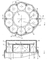
- FIGS. 2 and 3 show an embodiment of the transmission and receiving unit 15, wherein, for example a toe-shaped, generally can-shaped housing 20 in plan view is provided, in the interior of a common circuit board 21st with e.g. 10 IR transmitting diodes 22 and with a central IR receiving diode 23 is attached.
- the receiving diode 23 is in the range an opening 24 of an inner cylindrical shield 25, wherein the opening 24 in the bottom 26 of this shield 25 attached is.
- the reception range of the unit 15 separated from the transmission range, the transmission range by a generally annular space around the cylindrical shield 25 is formed around.
- Figure 3 is the angle of the Transmitting diodes 22 schematically with dashed lines at 27 and the receiving or input area of the receiving element 23 at 28 indicated.
- a housing cover for the housing 20 is a common, multi-segment, substantially plate-shaped lens element 29, within a shielding screen 30 for shielding is arranged by unwanted environmental radiation and with individual Lens segments 32, 33 for the receive and transmit elements is.
- the IR transmitting diodes 22 are accordingly upstream, in plan view (see Fig.2) substantially circular Transmit lens segments 32 and a middle receive lens segment 33 integrated in the lens element 29.
- the lens elements 32, 33 can, what is indicated schematically in Figure 3, by outside convex portions of the lens element 29 may be formed, preferably in combination with lattice structures or Fresnel lens structures, as will be explained in more detail below Figures 5 and 6 results.
- the aperture 30 preferably is formed integrally with the housing 20. Further shows 2 with dashed lines 34, a mounting plate on the Bottom or back of the housing 20 is attached and to Attachment of the optical assembly 15 to a not shown in detail Carrier, e.g. screwed by means of screw holes 35 Screws (not shown), serves.
- this beam becomes 27 then to a more or less parallel beam - at the Exit side of the respective lens segment 32 - collimated, where appropriate, this beam corresponding to half Opening angle of 1 ° or a few degrees diverges.
- lens segments 32, 33 with according to a circle around central receiving lens element 33 arranged transmitting lens segments 32, also other arrangements of the lens segments 32, 33 am Lens element 29 possible.
- an arrangement the outer transmitting lens segments according to a square or rectangle around a central receiving lens element - which in turn is larger can be as the transmitting lens elements - conceivable.
- FIG 4 an embodiment is shown in which in a Lens element 29A two groups of transmitting lens segments 32 - and Accordingly, two groups of it behind, in Fig.4 not shown IR transmitter diodes - on both sides of a turn larger, central receiving lens element 33 - again with it behind located IR receiving diode - are provided.
- the lens element 29A according to Figure 4 thus has an octagonal shape, with a large rectangular central part and two laterally attached trapezoidal parts, and it can turn off in one piece transparent plastic material, such as Acrylic or polycarbonate, be made.
- each individual Lens segment 32 or 33 on the outside or front is provided with a Fresnel lens structure 42 and 43, respectively, to the desired bundling or focusing of the beams 27 and 28, respectively (Fig.3) to reach.
- This structure of the lens element 29A (and Also of the lens element 29 according to Fig.2, 3 and the lens element 29B according to Fig.6 described below) can by Embossing, but also obtained by injection molding, the Fresnel lens structures 42, 43 - compared to information tracks on CD recording media are still rough structures - can be easily mitformed, creating a simple Production, especially in a mass production, allows becomes.
- material for the lens elements 29 (or 29A and 29B) can be used except acrylic or polycarbonate and epoxy resin and it can be a dye for filtering unwanted Frequencies are incorporated into the material.
- the actual filter element 29B is on a Support plate 29C attached, which consist of glass or acrylic glass can.
- IR transmitting diodes 22 are provided in the unit 15 more than ten, e.g. 12 or 16, etc.; It is also possible, instead of an IR receiving diode 23, an array of interconnected, in particular parallel-connected receiving diodes on the circuit board 21 ( Figure 3) to install.
- FIG. 7 shows an example of a driver circuit for the Transmitting elements 13, i. IR transmitter diodes 22, FIG it can be seen that in each case a plurality of transmitting diodes 22 in one Group 22.1, 22.2 connected in series and several transmitting diode groups 22.1, 22.2 can be connected in parallel. Every group 22.1, 22.2 is connected to a supply voltage VCC, wherein a capacitor 44 is connected in parallel for energy buffering.
- the from the pulse shaper 12 (Fig.1) coming to be sent signal is in electrical form of each transmitting diode group 22.1, 22.2 via a Driver gate 45 with inverting output and a resistor 46 supplied.
- the receiving diodes can or can 23 in a conventional manner to a power supply connected and via a bandpass filter (not shown) with the respective amplifier (16 in Figure 1).
Landscapes
- Physics & Mathematics (AREA)
- Electromagnetism (AREA)
- Engineering & Computer Science (AREA)
- Computer Networks & Wireless Communication (AREA)
- Signal Processing (AREA)
- Optical Communication System (AREA)
- Inspection Of Paper Currency And Valuable Securities (AREA)
- Cash Registers Or Receiving Machines (AREA)
- Devices For Conveying Motion By Means Of Endless Flexible Members (AREA)
- Glass Compositions (AREA)
- Percussion Or Vibration Massage (AREA)
- Surgical Instruments (AREA)
Description
Claims (22)
- Infrarot (IR-)-Übertragungseinrichtung mit in einem Gehäuse angeordneten IR-Sende- und -Empfangselementen, dadurch gekennzeichnet, dass ein gemeinsames, mehrsegmentiges Linsenelement (29, 29A, 29B) den IR-Elementen (22, 32) vorgeordnet ist, wobei jedem IR-Element (22, 32) ein eigenes Linsensegment (32, 33) des Linsenelementes (29, 29A, 29B) zugeordnet ist.
- Übertragungseinrichtung nach Anspruch 1, dadurch gekennzeichnet, dass als mehrsegmentiges Linsenelement (29, 29A, 29B) ein Spritzgussteil vorgesehen ist.
- Übertragungseinrichtung nach Anspruch 1, dadurch gekennzeichnet, dass als mehrsegmentiges Linsenelement (29, 29A, 29B) ein Pressteil vorgesehen ist.
- Übertragungseinrichtung nach Anspruch 1, dadurch gekennzeichnet, dass als mehrsegmentiges Linsenelement (29, 29A, 29B) ein Prägeteil vorgesehen ist.
- Übertragungseinrichtung nach einem der Ansprüche 1 bis 4, dadurch gekennzeichnet, dass das mehrsegmentige Linsenelement (29, 29A, 29B) zumindest bereichsweise als optisches Filter ausgebildet ist.
- Übertragungseinrichtung nach Anspruch 5, dadurch gekennzeichnet, dass das optische Filter durch Einbau eines Farbstoffes in das mehrsegmentige Linsenelement (29, 29A, 29B) gebildet ist.
- Übertragungseinrichtung nach einem der Ansprüche 1 bis 6; dadurch gekennzeichnet, dass das mehrsegmentige Linsenelement (29, 29A, 29B) aus Acrylglas besteht.
- Übertragungseinrichtung nach einem der Ansprüche 1 bis 6, dadurch gekennzeichnet, dass das mehrsegmentige Linsenelement (29, 29A, 29B) aus Polycarbonat besteht.
- Übertragungseinrichtung nach einem der Ansprüche 1 bis 8, dadurch gekennzeichnet, dass das mehrsegmentige Linsenelement (29, 29A) einstückig ist.
- Übertragungseinrichtung nach einem der Ansprüche 1 bis 9, dadurch gekennzeichnet, dass das mehrsegmentige Linsenelement (29B) mit einer transparenten Tragplatte (29C) zusammengebaut ist.
- Übertragungseinrichtung nach Anspruch 10, dadurch gekennzeichnet, dass die transparente Tragplatte (29C) aus Glas besteht.
- Übertragungseinrichtung nach einem der Ansprüche 1 bis 11, dadurch gekennzeichnet, dass das mehrsegmentige Linsenelement (29, 29A, 29B), gegebenenfalls zusammen mit der Tragplatte (29C), eine Abdeckung des Gehäuses (20) bildet.
- Übertragungseinrichtung nach einem der Ansprüche 1 bis 12, dadurch gekennzeichnet, dass zumindest ein Linsensegment (32, 33) als refraktiver Bereich ausgebildet ist.
- Übertragungseinrichtung nach einem der Ansprüche 1 bis 13, dadurch gekennzeichnet, dass zumindest ein Linsensegment (32, 33) als diffraktiver Bereich ausgebildet ist.
- Übertragungseinrichtung nach einem der Ansprüche 1 bis 13, dadurch gekennzeichnet, dass zumindest ein Linsensegment (32, 33) als Fresnellinse ausgebildet ist.
- Übertragungseinrichtung nach einem der Ansprüche 1 bis 15, dadurch gekennzeichnet, dass das mehrsegmentige Linsenelement (29, 29A, 29B) mit einem mittigen Empfangselement-Linsensegment (33) und einer Anzahl von außerhalb hievon gelegenen Sendeelement-Linsensegmenten (32) ausgebildet ist.
- Übertragungseinrichtung nach Anspruch 16, dadurch gekennzeichnet, dass die Sendeelement-Linsensegmente (32) entsprechend einer Kreislinie um das mittige Empfangselement-Linsensegment (33) angeordnet sind.
- Übertragungseinrichtung nach Anspruch 16 oder 17, dadurch gekennzeichnet, dass das Empfangselement-Linsensegment (33) in Draufsicht gesehen größer als jedes einzelne Sendeelement-Linsensegment (32) ist.
- Übertragungseinrichtung nach einem der Ansprüche 1 bis 18, dadurch gekennzeichnet, dass die IR-Sende- und Empfangselemente (22, 23) für eine inkohärente IR-Strahlung ausgebildet sind.
- Übertragungseinrichtung nach einem der Ansprüche 1 bis 19,
dadurch gekennzeichnet, dass die IR-Sende- und -Empfangselemente (22, 23) auf einer einzigen Leiterplatte (21) integriert sind. - Übertragungseinrichtung nach einem der Ansprüche 1 bis 20,
dadurch gekennzeichnet, dass die IR-Sendeelemente (22) durch IR-LED-Sendedioden mit integraler Optik gebildet sind. - Übertragungseinrichtung nach einem der Ansprüche 1 bis 21,
dadurch gekennzeichnet, dass die IR-Empfangfselemente (23) durch PIN- Dioden gebildet sind.
Priority Applications (1)
| Application Number | Priority Date | Filing Date | Title |
|---|---|---|---|
| AT02791583T ATE306149T1 (de) | 2001-11-20 | 2002-11-19 | Infrarot (ir) übertragungseinrichtung |
Applications Claiming Priority (3)
| Application Number | Priority Date | Filing Date | Title |
|---|---|---|---|
| AT18262001 | 2001-11-20 | ||
| AT0182601A AT412695B (de) | 2001-11-20 | 2001-11-20 | Infrarot (ir-)-übertragungseinrichtung |
| PCT/AT2002/000322 WO2003044993A1 (de) | 2001-11-20 | 2002-11-19 | Infrarot (ir-)-übertragungseinrichtung |
Publications (2)
| Publication Number | Publication Date |
|---|---|
| EP1446900A1 EP1446900A1 (de) | 2004-08-18 |
| EP1446900B1 true EP1446900B1 (de) | 2005-10-05 |
Family
ID=3689060
Family Applications (1)
| Application Number | Title | Priority Date | Filing Date |
|---|---|---|---|
| EP02791583A Expired - Lifetime EP1446900B1 (de) | 2001-11-20 | 2002-11-19 | Infrarot (ir) übertragungseinrichtung |
Country Status (9)
| Country | Link |
|---|---|
| US (1) | US20040252998A1 (de) |
| EP (1) | EP1446900B1 (de) |
| JP (1) | JP2005509386A (de) |
| KR (1) | KR20050044534A (de) |
| AT (2) | AT412695B (de) |
| AU (1) | AU2002357950A1 (de) |
| DE (1) | DE50204492D1 (de) |
| WO (1) | WO2003044993A1 (de) |
| ZA (1) | ZA200403369B (de) |
Families Citing this family (4)
| Publication number | Priority date | Publication date | Assignee | Title |
|---|---|---|---|---|
| US7809276B2 (en) * | 2004-11-30 | 2010-10-05 | Finisar Corporation | Inter-transceiver module communication for optimization of link between transceivers |
| JP5587095B2 (ja) * | 2010-08-18 | 2014-09-10 | 日東光学株式会社 | レンズ製造システム、レンズアレイおよびled照明装置 |
| US9245443B2 (en) * | 2013-02-21 | 2016-01-26 | The Boeing Company | Passenger services system for an aircraft |
| US20150270900A1 (en) * | 2014-03-19 | 2015-09-24 | Apple Inc. | Optical data transfer utilizing lens isolation |
Family Cites Families (11)
| Publication number | Priority date | Publication date | Assignee | Title |
|---|---|---|---|---|
| US5416627A (en) * | 1988-09-06 | 1995-05-16 | Wilmoth; Thomas E. | Method and apparatus for two way infrared communication |
| US5264955A (en) * | 1989-01-09 | 1993-11-23 | Canon Kabushiki Kaisha | Optical space communication apparatus |
| ATE120320T1 (de) * | 1989-08-21 | 1995-04-15 | Siemens Ag | System zur optischen datenübertragung, vorzugsweise für die automatische entrichtung von strassennutzungsgebühren. |
| GB2251700B (en) * | 1990-11-30 | 1994-08-24 | Combined Optical Ind Ltd | Multiple array lens |
| US5777768A (en) * | 1995-09-01 | 1998-07-07 | Astroterra Corporation | Multiple transmitter laser link |
| JPH09252285A (ja) * | 1996-03-15 | 1997-09-22 | Toshiba Corp | 近赤外線通信装置 |
| US6137535A (en) * | 1996-11-04 | 2000-10-24 | Eastman Kodak Company | Compact digital camera with segmented fields of view |
| US6119031A (en) * | 1996-11-21 | 2000-09-12 | Boston Scientific Corporation | Miniature spectrometer |
| US6036298A (en) * | 1997-06-30 | 2000-03-14 | Hewlett-Packard Company | Monochromatic optical sensing system for inkjet printing |
| US6006119A (en) * | 1998-02-04 | 1999-12-21 | Polestar Technologies, Inc. | Non-invasive optical measurement of blood hematocrit |
| US6037594A (en) * | 1998-03-05 | 2000-03-14 | Fresnel Technologies, Inc. | Motion detector with non-diverging insensitive zones |
-
2001
- 2001-11-20 AT AT0182601A patent/AT412695B/de not_active IP Right Cessation
-
2002
- 2002-11-19 WO PCT/AT2002/000322 patent/WO2003044993A1/de not_active Ceased
- 2002-11-19 DE DE50204492T patent/DE50204492D1/de not_active Expired - Lifetime
- 2002-11-19 US US10/495,986 patent/US20040252998A1/en not_active Abandoned
- 2002-11-19 AT AT02791583T patent/ATE306149T1/de active
- 2002-11-19 KR KR1020047007634A patent/KR20050044534A/ko not_active Withdrawn
- 2002-11-19 AU AU2002357950A patent/AU2002357950A1/en not_active Abandoned
- 2002-11-19 JP JP2003546513A patent/JP2005509386A/ja active Pending
- 2002-11-19 EP EP02791583A patent/EP1446900B1/de not_active Expired - Lifetime
-
2004
- 2004-05-04 ZA ZA2004/03369A patent/ZA200403369B/en unknown
Also Published As
| Publication number | Publication date |
|---|---|
| ATA18262001A (de) | 2004-10-15 |
| JP2005509386A (ja) | 2005-04-07 |
| EP1446900A1 (de) | 2004-08-18 |
| DE50204492D1 (de) | 2006-02-16 |
| WO2003044993A1 (de) | 2003-05-30 |
| AU2002357950A1 (en) | 2003-06-10 |
| US20040252998A1 (en) | 2004-12-16 |
| KR20050044534A (ko) | 2005-05-12 |
| AT412695B (de) | 2005-05-25 |
| ATE306149T1 (de) | 2005-10-15 |
| HK1069027A1 (en) | 2005-05-06 |
| ZA200403369B (en) | 2005-07-27 |
Similar Documents
| Publication | Publication Date | Title |
|---|---|---|
| EP0238977B1 (de) | Sende- und Empfangsmodul für ein bidirektionales Kommunikationsnetz, insbesondere ein Breitband-ISDN | |
| DE60028165T2 (de) | Optische Systemeinheit für einen optischen Transceiver | |
| EP0662273B1 (de) | Videoprojektionssystem | |
| EP1316165A1 (de) | Optischer modifizierer und verfahren zur herstellung hierfür | |
| DE102008023845B4 (de) | Optische Sensorvorrichtung zur Detektion von Umgebungslicht | |
| DE102008020171A1 (de) | Optische Sensorvorrichtung | |
| EP0040706A1 (de) | Optisches Kommunikationssystem | |
| DE2501791A1 (de) | System zur multiplexierung eines uebertragungskanals | |
| DE102005019562A1 (de) | Optisches Sende- und Empfangsmodul | |
| DE10051302C2 (de) | Laserentfernungsmessgerät für den Nah- und Fernbereich mit speziellem Empfänger | |
| EP0644668A1 (de) | Sende- und Empfangsmodul für eine bidirektionale optische Mehrkanal-Übertragung | |
| AT412695B (de) | Infrarot (ir-)-übertragungseinrichtung | |
| DE3889809T2 (de) | Optische Schaltungsmatrix, die über eine Maske mit Öffnungen eines bestimmten Musters verfügt und Verschlüsse, die zu diesem Muster passen. | |
| DE2012995C3 (de) | Fokussiervorrichtung | |
| DE69514032T2 (de) | Angepasstes optisches Element mit Oberflächenkrümmung für Ein- und Austritt von parallelen Lichtstrahlen | |
| DE69935646T2 (de) | Optisches Abtastgerät und optische Vorrichtung | |
| DE3205029A1 (de) | Optischer konzentrator/verteiler mit matrixaufbau | |
| EP2335104A1 (de) | Kompakter multiplexer/demultiplexer | |
| DE10249153A1 (de) | Kommunikationssystem mit einer Signalleitungsmatrix und einem Flächensignalrouter | |
| DE102018104198A1 (de) | Projektormodul | |
| DE112020003194T5 (de) | Lichtempfangsvorrichtung | |
| DE19845703C2 (de) | Bauteil zur optischen Datenübertragung | |
| DE102005010557B4 (de) | Optischer Multiplexer/Demultiplexer | |
| DE10311571A1 (de) | Bidirektionale Sende- und Empfangseinrichtung | |
| WO2004104665A1 (de) | Mikrooptikmodul mit spritzgegessenem gehäuse und verfahren zur herstellung desselben |
Legal Events
| Date | Code | Title | Description |
|---|---|---|---|
| PUAI | Public reference made under article 153(3) epc to a published international application that has entered the european phase |
Free format text: ORIGINAL CODE: 0009012 |
|
| 17P | Request for examination filed |
Effective date: 20040508 |
|
| AK | Designated contracting states |
Kind code of ref document: A1 Designated state(s): AT BE BG CH CY CZ DE DK EE ES FI FR GB GR IE IT LI LU MC NL PT SE SK TR |
|
| AX | Request for extension of the european patent |
Extension state: AL LT LV MK RO SI |
|
| RIN1 | Information on inventor provided before grant (corrected) |
Inventor name: RIEDER, HELMUT Inventor name: SCHALK, ANDREAS Inventor name: PAMMER, RAIMUND |
|
| GRAP | Despatch of communication of intention to grant a patent |
Free format text: ORIGINAL CODE: EPIDOSNIGR1 |
|
| REG | Reference to a national code |
Ref country code: HK Ref legal event code: DE Ref document number: 1069027 Country of ref document: HK |
|
| GRAS | Grant fee paid |
Free format text: ORIGINAL CODE: EPIDOSNIGR3 |
|
| GRAA | (expected) grant |
Free format text: ORIGINAL CODE: 0009210 |
|
| AK | Designated contracting states |
Kind code of ref document: B1 Designated state(s): AT BE BG CH CY CZ DE DK EE ES FI FR GB GR IE IT LI LU MC NL PT SE SK TR |
|
| AX | Request for extension of the european patent |
Extension state: RO SI |
|
| PG25 | Lapsed in a contracting state [announced via postgrant information from national office to epo] |
Ref country code: IT Free format text: LAPSE BECAUSE OF FAILURE TO SUBMIT A TRANSLATION OF THE DESCRIPTION OR TO PAY THE FEE WITHIN THE PRESCRIBED TIME-LIMIT;WARNING: LAPSES OF ITALIAN PATENTS WITH EFFECTIVE DATE BEFORE 2007 MAY HAVE OCCURRED AT ANY TIME BEFORE 2007. THE CORRECT EFFECTIVE DATE MAY BE DIFFERENT FROM THE ONE RECORDED. Effective date: 20051005 Ref country code: TR Free format text: LAPSE BECAUSE OF FAILURE TO SUBMIT A TRANSLATION OF THE DESCRIPTION OR TO PAY THE FEE WITHIN THE PRESCRIBED TIME-LIMIT Effective date: 20051005 Ref country code: EE Free format text: LAPSE BECAUSE OF FAILURE TO SUBMIT A TRANSLATION OF THE DESCRIPTION OR TO PAY THE FEE WITHIN THE PRESCRIBED TIME-LIMIT Effective date: 20051005 Ref country code: FI Free format text: LAPSE BECAUSE OF FAILURE TO SUBMIT A TRANSLATION OF THE DESCRIPTION OR TO PAY THE FEE WITHIN THE PRESCRIBED TIME-LIMIT Effective date: 20051005 Ref country code: IE Free format text: LAPSE BECAUSE OF FAILURE TO SUBMIT A TRANSLATION OF THE DESCRIPTION OR TO PAY THE FEE WITHIN THE PRESCRIBED TIME-LIMIT Effective date: 20051005 Ref country code: GB Free format text: LAPSE BECAUSE OF FAILURE TO SUBMIT A TRANSLATION OF THE DESCRIPTION OR TO PAY THE FEE WITHIN THE PRESCRIBED TIME-LIMIT Effective date: 20051005 |
|
| REG | Reference to a national code |
Ref country code: GB Ref legal event code: FG4D Free format text: NOT ENGLISH |
|
| PGFP | Annual fee paid to national office [announced via postgrant information from national office to epo] |
Ref country code: CZ Payment date: 20051006 Year of fee payment: 4 |
|
| REG | Reference to a national code |
Ref country code: CH Ref legal event code: EP |
|
| PGFP | Annual fee paid to national office [announced via postgrant information from national office to epo] |
Ref country code: SK Payment date: 20051021 Year of fee payment: 4 |
|
| REG | Reference to a national code |
Ref country code: IE Ref legal event code: FG4D Free format text: LANGUAGE OF EP DOCUMENT: GERMAN |
|
| PG25 | Lapsed in a contracting state [announced via postgrant information from national office to epo] |
Ref country code: CY Free format text: LAPSE BECAUSE OF FAILURE TO SUBMIT A TRANSLATION OF THE DESCRIPTION OR TO PAY THE FEE WITHIN THE PRESCRIBED TIME-LIMIT Effective date: 20051119 |
|
| PG25 | Lapsed in a contracting state [announced via postgrant information from national office to epo] |
Ref country code: MC Free format text: LAPSE BECAUSE OF NON-PAYMENT OF DUE FEES Effective date: 20051130 Ref country code: BE Free format text: LAPSE BECAUSE OF NON-PAYMENT OF DUE FEES Effective date: 20051130 |
|
| PG25 | Lapsed in a contracting state [announced via postgrant information from national office to epo] |
Ref country code: LU Free format text: LAPSE BECAUSE OF NON-PAYMENT OF DUE FEES Effective date: 20051205 |
|
| REG | Reference to a national code |
Ref country code: HK Ref legal event code: GR Ref document number: 1069027 Country of ref document: HK |
|
| PG25 | Lapsed in a contracting state [announced via postgrant information from national office to epo] |
Ref country code: DK Free format text: LAPSE BECAUSE OF FAILURE TO SUBMIT A TRANSLATION OF THE DESCRIPTION OR TO PAY THE FEE WITHIN THE PRESCRIBED TIME-LIMIT Effective date: 20060105 Ref country code: SE Free format text: LAPSE BECAUSE OF FAILURE TO SUBMIT A TRANSLATION OF THE DESCRIPTION OR TO PAY THE FEE WITHIN THE PRESCRIBED TIME-LIMIT Effective date: 20060105 Ref country code: GR Free format text: LAPSE BECAUSE OF FAILURE TO SUBMIT A TRANSLATION OF THE DESCRIPTION OR TO PAY THE FEE WITHIN THE PRESCRIBED TIME-LIMIT Effective date: 20060105 Ref country code: BG Free format text: LAPSE BECAUSE OF FAILURE TO SUBMIT A TRANSLATION OF THE DESCRIPTION OR TO PAY THE FEE WITHIN THE PRESCRIBED TIME-LIMIT Effective date: 20060105 |
|
| PG25 | Lapsed in a contracting state [announced via postgrant information from national office to epo] |
Ref country code: ES Free format text: LAPSE BECAUSE OF FAILURE TO SUBMIT A TRANSLATION OF THE DESCRIPTION OR TO PAY THE FEE WITHIN THE PRESCRIBED TIME-LIMIT Effective date: 20060116 |
|
| REF | Corresponds to: |
Ref document number: 50204492 Country of ref document: DE Date of ref document: 20060216 Kind code of ref document: P |
|
| PG25 | Lapsed in a contracting state [announced via postgrant information from national office to epo] |
Ref country code: PT Free format text: LAPSE BECAUSE OF FAILURE TO SUBMIT A TRANSLATION OF THE DESCRIPTION OR TO PAY THE FEE WITHIN THE PRESCRIBED TIME-LIMIT Effective date: 20060306 |
|
| GBV | Gb: ep patent (uk) treated as always having been void in accordance with gb section 77(7)/1977 [no translation filed] |
Effective date: 20051005 |
|
| REG | Reference to a national code |
Ref country code: IE Ref legal event code: FD4D |
|
| PLBE | No opposition filed within time limit |
Free format text: ORIGINAL CODE: 0009261 |
|
| STAA | Information on the status of an ep patent application or granted ep patent |
Free format text: STATUS: NO OPPOSITION FILED WITHIN TIME LIMIT |
|
| 26N | No opposition filed |
Effective date: 20060706 |
|
| PG25 | Lapsed in a contracting state [announced via postgrant information from national office to epo] |
Ref country code: FR Free format text: LAPSE BECAUSE OF FAILURE TO SUBMIT A TRANSLATION OF THE DESCRIPTION OR TO PAY THE FEE WITHIN THE PRESCRIBED TIME-LIMIT Effective date: 20061020 |
|
| PG25 | Lapsed in a contracting state [announced via postgrant information from national office to epo] |
Ref country code: SK Free format text: LAPSE BECAUSE OF NON-PAYMENT OF DUE FEES Effective date: 20061119 |
|
| PG25 | Lapsed in a contracting state [announced via postgrant information from national office to epo] |
Ref country code: LI Free format text: LAPSE BECAUSE OF NON-PAYMENT OF DUE FEES Effective date: 20061130 Ref country code: CH Free format text: LAPSE BECAUSE OF NON-PAYMENT OF DUE FEES Effective date: 20061130 |
|
| EN | Fr: translation not filed | ||
| PG25 | Lapsed in a contracting state [announced via postgrant information from national office to epo] |
Ref country code: NL Free format text: LAPSE BECAUSE OF NON-PAYMENT OF DUE FEES Effective date: 20070601 |
|
| REG | Reference to a national code |
Ref country code: CH Ref legal event code: PL |
|
| NLV4 | Nl: lapsed or anulled due to non-payment of the annual fee |
Effective date: 20070601 |
|
| BERE | Be: lapsed |
Owner name: EFKON AG Effective date: 20051130 |
|
| PG25 | Lapsed in a contracting state [announced via postgrant information from national office to epo] |
Ref country code: CZ Free format text: LAPSE BECAUSE OF NON-PAYMENT OF DUE FEES Effective date: 20061119 |
|
| PG25 | Lapsed in a contracting state [announced via postgrant information from national office to epo] |
Ref country code: FR Free format text: LAPSE BECAUSE OF FAILURE TO SUBMIT A TRANSLATION OF THE DESCRIPTION OR TO PAY THE FEE WITHIN THE PRESCRIBED TIME-LIMIT Effective date: 20051130 |
|
| PG25 | Lapsed in a contracting state [announced via postgrant information from national office to epo] |
Ref country code: FR Free format text: LAPSE BECAUSE OF FAILURE TO SUBMIT A TRANSLATION OF THE DESCRIPTION OR TO PAY THE FEE WITHIN THE PRESCRIBED TIME-LIMIT Effective date: 20051005 |
|
| PGFP | Annual fee paid to national office [announced via postgrant information from national office to epo] |
Ref country code: DE Payment date: 20120823 Year of fee payment: 11 |
|
| PGFP | Annual fee paid to national office [announced via postgrant information from national office to epo] |
Ref country code: AT Payment date: 20121127 Year of fee payment: 11 |
|
| REG | Reference to a national code |
Ref country code: DE Ref legal event code: R119 Ref document number: 50204492 Country of ref document: DE |
|
| REG | Reference to a national code |
Ref country code: AT Ref legal event code: MM01 Ref document number: 306149 Country of ref document: AT Kind code of ref document: T Effective date: 20131119 |
|
| REG | Reference to a national code |
Ref country code: DE Ref legal event code: R079 Ref document number: 50204492 Country of ref document: DE Free format text: PREVIOUS MAIN CLASS: H04B0010100000 Ipc: H04B0010110000 |
|
| PG25 | Lapsed in a contracting state [announced via postgrant information from national office to epo] |
Ref country code: DE Free format text: LAPSE BECAUSE OF NON-PAYMENT OF DUE FEES Effective date: 20140603 Ref country code: AT Free format text: LAPSE BECAUSE OF NON-PAYMENT OF DUE FEES Effective date: 20131119 |
|
| REG | Reference to a national code |
Ref country code: DE Ref legal event code: R079 Ref document number: 50204492 Country of ref document: DE Free format text: PREVIOUS MAIN CLASS: H04B0010100000 Ipc: H04B0010110000 Effective date: 20140728 Ref country code: DE Ref legal event code: R119 Ref document number: 50204492 Country of ref document: DE Effective date: 20140603 |