EP1446810B1 - Procede et dispositif d'enregistrement d'objets - Google Patents
Procede et dispositif d'enregistrement d'objets Download PDFInfo
- Publication number
- EP1446810B1 EP1446810B1 EP02783377A EP02783377A EP1446810B1 EP 1446810 B1 EP1446810 B1 EP 1446810B1 EP 02783377 A EP02783377 A EP 02783377A EP 02783377 A EP02783377 A EP 02783377A EP 1446810 B1 EP1446810 B1 EP 1446810B1
- Authority
- EP
- European Patent Office
- Prior art keywords
- aperture
- ray radiation
- radiation source
- dimension
- recording
- Prior art date
- Legal status (The legal status is an assumption and is not a legal conclusion. Google has not performed a legal analysis and makes no representation as to the accuracy of the status listed.)
- Expired - Lifetime
Links
- 238000000034 method Methods 0.000 title claims abstract description 15
- 230000005855 radiation Effects 0.000 claims abstract description 40
- 238000003384 imaging method Methods 0.000 claims description 9
- 230000003287 optical effect Effects 0.000 claims description 3
- 238000001514 detection method Methods 0.000 claims 6
- 238000009434 installation Methods 0.000 claims 6
- 230000001419 dependent effect Effects 0.000 abstract description 8
- 238000005259 measurement Methods 0.000 description 3
- 210000000481 breast Anatomy 0.000 description 2
- 230000006835 compression Effects 0.000 description 2
- 238000007906 compression Methods 0.000 description 2
- 206010052128 Glare Diseases 0.000 description 1
- 238000013459 approach Methods 0.000 description 1
- 230000003247 decreasing effect Effects 0.000 description 1
- 230000005670 electromagnetic radiation Effects 0.000 description 1
- 238000011156 evaluation Methods 0.000 description 1
- 239000011888 foil Substances 0.000 description 1
- 230000005865 ionizing radiation Effects 0.000 description 1
- 238000009607 mammography Methods 0.000 description 1
- 239000000463 material Substances 0.000 description 1
- 238000012986 modification Methods 0.000 description 1
- 230000004048 modification Effects 0.000 description 1
- 238000001228 spectrum Methods 0.000 description 1
- 238000012360 testing method Methods 0.000 description 1
Images


Classifications
-
- G—PHYSICS
- G21—NUCLEAR PHYSICS; NUCLEAR ENGINEERING
- G21K—TECHNIQUES FOR HANDLING PARTICLES OR IONISING RADIATION NOT OTHERWISE PROVIDED FOR; IRRADIATION DEVICES; GAMMA RAY OR X-RAY MICROSCOPES
- G21K1/00—Arrangements for handling particles or ionising radiation, e.g. focusing or moderating
- G21K1/02—Arrangements for handling particles or ionising radiation, e.g. focusing or moderating using diaphragms, collimators
- G21K1/04—Arrangements for handling particles or ionising radiation, e.g. focusing or moderating using diaphragms, collimators using variable diaphragms, shutters, choppers
Definitions
- the invention relates to a method according to the preamble of claim 1 and to a device according to the preamble of claim 9.
- moving shutters for metering the amount of light
- shutter shutter
- the width of the aperture for varying the amount of light can be set differently.
- diaphragms are known as collimators, which serve with constant dimensions to reduce the radiation dose produced but also according to US-A-4,773,087 be used to reduce the scattered radiation.
- Collimators may also be adjustable to limit the irradiated area adapted to the object to be photographed. So in the US-A-4,122,350 a size-adjustable collimator for limiting the irradiated area in mammography is shown, wherein no relative movement between the object and the X-ray source takes place.
- An adjustable collimator is known that can limit the height of the irradiated area in cephalometric panoramic exposures.
- the width of the intersection of the cone and the plane of rotation is determined by a non-adjustable slot at the exit of the X-ray source. Perpendicular to the pivot plane, the cone of rays is limited by the height-adjustable collimator, with display bars indicating the limit in height.
- An adjustable collimator is known which limits the irradiated area depending on the size of the film cassette used. In the recording mode shown, there is no relative movement between the object and the X-ray source. As a general rule In radiology, it is known to use collimators to confine the irradiated area and to represent the limited area for the control of the same on the object (patient) before the actual recording by means of visible light.
- Collimators are also used to confine the X-ray radiation when using line detectors, such that only the radiation-sensitive line detector is irradiated.
- line detectors such that only the radiation-sensitive line detector is irradiated.
- raster screens are used to reduce stray radiation.
- this method of reducing the stray radiation also simultaneously weakens the useful radiation, so that high doses of X-radiation must be used to produce a high-contrast image.
- These ray patterns which are located between the object and the image, are constant in their dimensions. The recording of unwanted scattered radiation on the recording medium generally leads to a deteriorated useful signal / interference signal ratio during image acquisition and thus to a non-optimal image quality.
- EP-A-0 223 432 For the purpose of equalizing the exposure of X-ray images, it is known to control a multiplicity of diaphragms by the patient body as a function of the attenuation of the X-radiation, with a plurality of detectors being arranged behind the patient for detecting the X-radiation intensity.
- Out US-A-5,627,869 It is known to set the collimator in mammographic individual recordings so that the size of the X-ray cone is matched to the size of the breast compression disc and its distance from the X-ray source so that the X-ray cone covers the breast compression disc but does not extend beyond its edges. This is to reduce the scattered radiation.
- the scattered radiation can be particularly well reduced, which increases the image quality. It has been shown in X-ray photography that the object size-dependent aperture leads to sharper images, which allow a better interpretation of the image of the object.
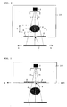
- FIG. 1 shows a first embodiment in plan, in which by means of an object-dependent adjusted aperture, the scattered radiation is reduced.
- FIG. 1 shows schematically a device 1, by means of which an object 4 is transilluminated in order to produce on a receiving means 3 an image of the object 4.
- the device 1 is, for example, an industrial or medical X-ray system, which illuminates a technical object 4, or a patient, and generates the image on an X-ray film or an X-ray plate 3.
- the X-ray source 2 is an X-ray tube.
- the X-ray source 2 which is arranged in a schematically illustrated housing, generates X-rays, their cones or otherwise differently shaped outline with the boundary lines 5 in the Figure is indicated.
- the x-ray source 2 is located, for example, in a housing 10, which is closed by the aperture 6 to the object 4 out.
- the panel can also be arranged separately, housing independent.
- the diaphragm 6 has an opening 9, through which a part of the X-rays can escape through the aperture from the housing 10, while the rest of the X-rays is prevented by the diaphragm 6 from exiting the housing.
- the object is placed so that it can be detected by the entire cone of rays, as it exits from the source 2 and is indicated by the lines 5.
- the radiation emerging from the source 2 can be limited in a known manner by an only indicated collimator 2 ';
- the lines 5 represent the already limited radiation, which may also extend only over a part of the object 4, if only this part is to be imaged or only this part is moved relative to the beam.
- the opening 9 of the aperture 6 shown in section is set in any case in the aperture dimension, which corresponds to the direction of movement, as a function of the size of the object 4.
- the width b of the aperture 9 is set, which is in the direction of movement (arrow A).
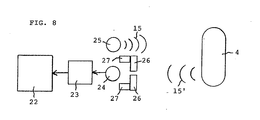
- FIG. 1 schematically represented by two sensors 8, which measure the object 4, for example, contactless by an ultrasonic measurement or an optical measurement. Sensors may also be provided which contact the object to accommodate its dimension for the aperture setting.
- the size of the Aperture 9 determined and adjusted for example by servomotors 7, which are operated by the controller 11.
- One in the recording situation of FIG. 1 dimension of interest is the width B of the object, which is traversed by the relative movement in the direction of an arrow A.
- the width b of the slot-shaped aperture opening of the diaphragm 6 is set in the present example.
- the width b of the aperture is x times smaller than the width B of the object, where x is in the range of 10 to 100,000, so that the slot width is thus 10 times to 100,000 times less than the width B of the object.
- the diaphragm aperture can also be chosen to be proportional to the width B of the part of the object. Further, preferably, the height of the slot opening of the aperture 6 corresponding to the height of the object 4, that is, the extension perpendicular to the plane of the object 4, set.
- the same divider can be used as in the width setting, so that the slot height is also 10 times smaller to 100,000 times smaller than the height of the object 4.
- the object 4 is then imaged accordingly by a limited by the object size dependent aperture X-ray, in which case the object and the imaging means or the X-ray plate 3 are moved together several times along the stationary and dimmed X-ray source 2, in each case correspondingly displaced in height, so that the image is produced strip by strip.
- the object and the imaging means or the X-ray plate 3 are moved together several times along the stationary and dimmed X-ray source 2, in each case correspondingly displaced in height, so that the image is produced strip by strip.
- FIG. 2 schematically shows a view of the diaphragm 6, wherein this according to FIG. 1 a slit with the slot 9 is.
- This slot 9 can be adjusted in height h and its width b by means of movable diaphragm elements 12 and 13, which are displaceable relative to one another. This is done by the in FIG. 1 indicated actuating means, which may be motor, pneumatic or hydraulic actuating means.
- Figure 3 shows a corresponding sectional view through the aperture 6 of FIG. 2 , wherein like elements are provided with the same reference numerals.
- the diaphragm can also be set differently in its depth t, for which purpose preferably also the depth T of the object is measured. A depth adjustment can take place in that several of the apertures are connected in series, as in FIG. 3 with a further aperture 6 'is merely indicated.
- the use according to the invention of the diaphragm for reducing the stray radiation is possible for the entire spectrum of electromagnetic radiation.
- the highest possible proportionality e.g. between 1: 10,000 to 1: 100,000.
- the width of the aperture of the aperture to the micrometer range desirable.
- the optimum ratio diaphragm: object can only be realized technically complex, e.g. just for apertures in the range of 10 to 100 microns. In this case, a lower proportionality is decreased, e.g. 1:10 or 1:50.
- FIG. 4 shows a further embodiment of the invention, wherein like reference numerals as used in the previous figures denote like elements.
- the aperture also shown cut is between the object 4 and the receiving means 3 arranged.
- the object 4 and the imaging means 3 are moved past the stationary diaphragm 6 and the stationary X-ray source according to the arrows A.
- this passing movement takes place several times with different shifted height positions of diaphragm and object.
- the means 7, 8 and 11 are no longer shown, but are also present in the device.
- the dimension of the diaphragm is also set here, which corresponds to the relative movement, in the present case again the width b proportional to the width of the object 4.
- the beam 5 exits from the source 2, possibly through a collimator.
- FIG. 5 shows a further embodiment in which in turn the same elements are provided with the same reference numerals and the means 7, 8 and 11 are not shown, but the X-ray source 2 and the diaphragm 6 according to the arrow A on the fixed object and the stationary imaging means 3 are moved past , Again, the image on the imaging means 3 line by line corresponding to the height of the slot of the diaphragm 6 can be generated.
- FIG. 6 shows a corresponding embodiment, wherein, however, the diaphragm between the object 4 and the imaging means 3 is arranged. Also the aperture of the Figures 5 and 6 are each set in their slot width b according to the direction of the process of the diaphragm.
- FIG. 7 shows a further embodiment in which two apertures 6 and 16 are provided with the openings 9 and 19, wherein the one aperture between the X-ray source and the object and the other diaphragm between the object and the imaging means 3 is provided.
- the apertures are moved synchronously with the X-ray source 2 in order to scan the object line by line.
- the aperture 9 is doing again in the width b set object-dependent, preferably this also takes place at the aperture 19th
- a preferred application of the invention is in the medical X-ray technology and in the industrial X-ray technology for testing materials.
- the tripod is a commercially available multistat with film cassettes or storage foils. On the tripod a panel with control is installed later.
- the reduction of the scattered radiation can be calculated as a first approximation as a proportion, which results from the total irradiated area without aperture to the passage area of the aperture.
- the number of passes is usually 1.
- the time required for the linear movement in direction A depends on the size of the object and is practicable between 0.1 and 10 seconds.
Landscapes
- Physics & Mathematics (AREA)
- Spectroscopy & Molecular Physics (AREA)
- Engineering & Computer Science (AREA)
- General Engineering & Computer Science (AREA)
- High Energy & Nuclear Physics (AREA)
- Apparatus For Radiation Diagnosis (AREA)
- Radiography Using Non-Light Waves (AREA)
- Manufacturing Optical Record Carriers (AREA)
- Heating, Cooling, Or Curing Plastics Or The Like In General (AREA)
- Recording Measured Values (AREA)
- Crystals, And After-Treatments Of Crystals (AREA)
- Manufacture, Treatment Of Glass Fibers (AREA)
- Circuits Of Receivers In General (AREA)
Claims (13)
- Procédé d'enregistrement d'un objet (4) par reproduction au moyen d'une source de rayons X (2) sur un support d'enregistrement (3), en particulier un film, dans lequel l'objet est radiographié et, par enregistrement à travers au moins un diaphragme (6) et un mouvement relatif de l'objet d'une part, et du diaphragme et du support d'enregistrement et éventuellement de la source de rayons X d'autre part, l'objet est enregistré par sections en continu ou en discontinu, dans lequel la taille de l'ouverture de diaphragme (9, 19) dans au moins la dimension de l'ouverture de diaphragme, qui se situe dans la direction du mouvement relatif, est réglée en fonction de la taille de l'objet, caractérisé en ce que, comme taille d'objet, on tient compte du volume de l'objet ou de la surface de l'objet tournée vers les rayons X ou uniquement d'une dimension de cette surface, et en ce que la taille de l'objet est détectée au moyen d'un dispositif de détection, qui présente des capteurs mécaniques et/ou des capteurs optiques ou des capteurs à ultrasons (8) pour détecter le volume de l'objet ou au moins une dimension de l'objet, l'ouverture de diaphragme (9, 19) étant réglée en particulier avant ou au cours de chaque enregistrement.
- Procédé selon la revendication 1, caractérisé en ce que les rayons X (5) sont limités devant le diaphragme par au moins un collimateur (2').
- Procédé selon l'une quelconque des revendications 1 ou 2, caractérisé en ce que l'objet (4) et le support d'enregistrement (3) sont déplacés devant la source fixe de rayons X (2) et le diaphragme fixe (6), dans lequel le diaphragme (6) est aménagé entre la source de rayons X (2) et l'objet (4) ou le diaphragme (6) est aménagé entre l'objet (4) et le support d'enregistrement.
- Procédé selon l'une quelconque des revendications 1 ou 2, caractérisé en ce que la source de rayons X (2) et le diaphragme (6) sont déplacés devant l'objet fixe (4) et le support d'enregistrement fixe (3), dans lequel le diaphragme (6) est aménagé entre la source de rayons X (2) et l'objet (4) ou le diaphragme (6) est aménagé entre l'objet (4) et le support d'enregistrement (3) ou dans lequel un premier diaphragme (6) est aménagé entre la source de rayons X (2) et l'objet (4) et un second diaphragme (16) est aménagé entre l'objet (4) et le support d'enregistrement (3).
- Procédé selon l'une quelconque des revendications 1 à 4, caractérisé en ce que le mouvement relatif s'effectue dans le sens de la largeur B de l'objet et la largeur b de l'ouverture du diaphragme est réglée en fonction de la taille de l'objet et, éventuellement, également la hauteur h de l'ouverture du diaphragme.
- Procédé selon l'une quelconque des revendications 1 à 4, caractérisé en ce que le mouvement relatif s'effectue dans le sens de la hauteur de l'objet et la hauteur h de l'ouverture du diaphragme est réglée en fonction de la hauteur de l'objet.
- Procédé selon l'une quelconque des revendications 5 ou 6,
caractérisé en ce que l'épaisseur t du diaphragme est également réglée, en particulier, en fonction de l'épaisseur T de l'objet. - Procédé selon l'une quelconque des revendications 1 à 7,
caractérisé en ce que la dimension d'ouverture du diaphragme par rapport à la dimension de l'objet est réglée dans une plage de 1:10 à 1:100 000, de préférence dans une plage de 1:100 à 1:100 000, mieux encore dans une plage de 1:1000 à 1:100 000 et, bien mieux encore, dans une plage de 1:10 000 à 1:100 000. - Dispositif pour enregistrer un objet sur un support d'enregistrement (3) au moyen d'une source de rayons X (2), dans lequel le dispositif comprend au moins un diaphragme (6) et un moyen de déplacement pour un mouvement relatif entre un diaphragme (6) et un objet (4), dans lequel il est prévu un dispositif de réglage (7, 11) pour régler au moins une dimension d'ouverture de diaphragme et un dispositif de détection (8, 11) pour détecter au moins une dimension de l'objet, dans lequel le dispositif de réglage est relié au dispositif de détection de sorte que la au moins une dimension d'ouverture du diaphragme puisse être réglée en fonction de la au moins une dimension d'objet détectée et dans lequel la au moins une dimension d'ouverture réglable du diaphragme peut être réglée en direction du mouvement relatif, caractérisé en ce que, comme taille d'objet, on peut tenir compte du volume de l'objet ou de la surface de l'objet tournée vers les rayons X ou seulement d'une dimension de cette surface et en ce que le dispositif de détection présente des capteurs mécaniques et/ou des capteurs optiques ou des capteurs à ultrasons (8) pour détecter le volume de l'objet ou au moins une dimension de l'objet.
- Dispositif selon la revendication 9, caractérisé en ce qu'il comprend une source de rayons X (2), dont les rayons sont limités par au moins un collimateur (2').
- Dispositif selon la revendication 9 ou 11, caractérisé en ce qu'il comprend un porte-objet (4') et en ce que le porte-objet, d'une part, et le diaphragme (6), d'autre part, peuvent être déplacés l'un par rapport à l'autre via les moyens de déplacement (7, 11).
- Dispositif selon la revendication 11, caractérisé en ce que la source de rayons X (2) et le diaphragme (6) sont aménagés fixes dans le dispositif et en ce que le porte-objet (4') et le support d'enregistrement (3) sont en outre aménagés mobiles pour assurer le mouvement relatif, dans lequel le diaphragme (6) est aménagé entre la source de rayons X (2) et le porte-objet (4') ou dans lequel le diaphragme (6) est aménagé entre le porte-objet et le support d'enregistrement (3).
- Dispositif selon la revendication 11, caractérisé en ce que le porte-objet et le support d'enregistrement (3) sont aménagés fixes dans le dispositif et la source de rayons X (2) et le diaphragme (6) sont en outre aménagés mobiles pour assurer le mouvement relatif, dans lequel le diaphragme (6) est aménagé entre la source de rayons X (2) et le porte-objet, dans lequel le diaphragme (6) est aménagé entre le porte-objet et le support d'enregistrement (3) ou dans lequel un premier diaphragme (6) est aménagé entre la source de rayons X (2) et le porte-objet et un second diaphragme (16) couplé en mouvement au premier diaphragme est aménagé entre le porte-objet le support d'enregistrement.
Priority Applications (1)
| Application Number | Priority Date | Filing Date | Title |
|---|---|---|---|
| EP02783377A EP1446810B1 (fr) | 2001-11-22 | 2002-11-15 | Procede et dispositif d'enregistrement d'objets |
Applications Claiming Priority (4)
| Application Number | Priority Date | Filing Date | Title |
|---|---|---|---|
| EP01127371A EP1315177A1 (fr) | 2001-11-22 | 2001-11-22 | Procédé et dispositif pour l'imagerie d'objets |
| EP01127371 | 2001-11-22 | ||
| PCT/IB2002/004765 WO2003044807A1 (fr) | 2001-11-22 | 2002-11-15 | Procede et dispositif d'enregistrement d'objets |
| EP02783377A EP1446810B1 (fr) | 2001-11-22 | 2002-11-15 | Procede et dispositif d'enregistrement d'objets |
Publications (2)
| Publication Number | Publication Date |
|---|---|
| EP1446810A1 EP1446810A1 (fr) | 2004-08-18 |
| EP1446810B1 true EP1446810B1 (fr) | 2010-09-01 |
Family
ID=8179271
Family Applications (2)
| Application Number | Title | Priority Date | Filing Date |
|---|---|---|---|
| EP01127371A Withdrawn EP1315177A1 (fr) | 2001-11-22 | 2001-11-22 | Procédé et dispositif pour l'imagerie d'objets |
| EP02783377A Expired - Lifetime EP1446810B1 (fr) | 2001-11-22 | 2002-11-15 | Procede et dispositif d'enregistrement d'objets |
Family Applications Before (1)
| Application Number | Title | Priority Date | Filing Date |
|---|---|---|---|
| EP01127371A Withdrawn EP1315177A1 (fr) | 2001-11-22 | 2001-11-22 | Procédé et dispositif pour l'imagerie d'objets |
Country Status (6)
| Country | Link |
|---|---|
| US (1) | US7372945B2 (fr) |
| EP (2) | EP1315177A1 (fr) |
| AT (1) | ATE479994T1 (fr) |
| AU (1) | AU2002347443A1 (fr) |
| DE (1) | DE50214635D1 (fr) |
| WO (1) | WO2003044807A1 (fr) |
Families Citing this family (1)
| Publication number | Priority date | Publication date | Assignee | Title |
|---|---|---|---|---|
| US9566040B2 (en) * | 2014-05-14 | 2017-02-14 | Swissray Asia Healthcare Co., Ltd. | Automatic collimator adjustment device with depth camera and method for medical treatment equipment |
Family Cites Families (15)
| Publication number | Priority date | Publication date | Assignee | Title |
|---|---|---|---|---|
| US3518435A (en) * | 1967-11-24 | 1970-06-30 | Philips Corp | Automatic x-radiation collimating apparatus responsive to film cassette size |
| SU591239A1 (ru) * | 1976-01-24 | 1978-02-05 | Куйбышевский Ордена Трудового Красного Знамени Авиационный Институт Им. Академика С.П.Королева | Ультразвуковое коллиматорное устройство |
| US4122350A (en) * | 1977-11-21 | 1978-10-24 | Julius Lipthay | Adjustable collimator for mammography |
| US4603427A (en) * | 1983-12-16 | 1986-07-29 | Alpern Michael C | Collimator in a panoramic dental X-ray apparatus |
| DE3500812A1 (de) * | 1985-01-11 | 1986-07-17 | Siemens AG, 1000 Berlin und 8000 München | Roentgendiagnostikeinrichtung mit halbtransparenter blende |
| CA1244971A (fr) * | 1985-11-14 | 1988-11-15 | Shih-Ping Wang | Methode et systeme de radiographie aux rx |
| DE4210120C1 (en) * | 1992-03-27 | 1993-08-05 | Siemens Ag, 8000 Muenchen, De | X=ray appts. for peripheral angiography - calculates relative positioning of appts. and patient support using data derived from patient |
| US5244136A (en) * | 1992-04-03 | 1993-09-14 | Vincent Collaso | Expandable water-proof pouch |
| US5224136A (en) | 1992-06-30 | 1993-06-29 | General Electric Company | Helical scanning computed tomography apparatus with constrained tracking of the x-ray source |
| US5627869A (en) * | 1995-11-22 | 1997-05-06 | Thermotrex Corporation | Mammography apparatus with proportional collimation |
| US5818902A (en) * | 1996-03-01 | 1998-10-06 | Elekta Ab | Intensity modulated arc therapy with dynamic multi-leaf collimation |
| US6502984B2 (en) * | 1997-01-17 | 2003-01-07 | Canon Kabushiki Kaisha | Radiographic apparatus |
| US6055295A (en) * | 1998-01-29 | 2000-04-25 | Siemens Corporate Research, Inc. | Method and apparatus for automatic collimation in x-ray peripheral imaging |
| US6496557B2 (en) * | 2000-02-09 | 2002-12-17 | Hologic, Inc. | Two-dimensional slot x-ray bone densitometry, radiography and tomography |
| DE102005006895B4 (de) * | 2005-02-15 | 2010-11-18 | Siemens Ag | Röntgendiagnostikeinrichtung sowie Verfahren zu deren Regelung |
-
2001
- 2001-11-22 EP EP01127371A patent/EP1315177A1/fr not_active Withdrawn
-
2002
- 2002-11-15 EP EP02783377A patent/EP1446810B1/fr not_active Expired - Lifetime
- 2002-11-15 AT AT02783377T patent/ATE479994T1/de not_active IP Right Cessation
- 2002-11-15 US US10/496,038 patent/US7372945B2/en not_active Expired - Fee Related
- 2002-11-15 DE DE50214635T patent/DE50214635D1/de not_active Expired - Lifetime
- 2002-11-15 AU AU2002347443A patent/AU2002347443A1/en not_active Abandoned
- 2002-11-15 WO PCT/IB2002/004765 patent/WO2003044807A1/fr not_active Application Discontinuation
Also Published As
| Publication number | Publication date |
|---|---|
| DE50214635D1 (de) | 2010-10-14 |
| ATE479994T1 (de) | 2010-09-15 |
| US7372945B2 (en) | 2008-05-13 |
| AU2002347443A1 (en) | 2003-06-10 |
| EP1446810A1 (fr) | 2004-08-18 |
| WO2003044807A1 (fr) | 2003-05-30 |
| EP1315177A1 (fr) | 2003-05-28 |
| US20050008122A1 (en) | 2005-01-13 |
Similar Documents
| Publication | Publication Date | Title |
|---|---|---|
| DE2732073C2 (de) | Computertomograph | |
| DE602004012080T2 (de) | Nachweis von ionisierender strahlung auf dual-energie-scanning-basis | |
| DE102008049708B4 (de) | Blende und Blendenvorrichtung zur gezielten Beeinflussung von Röntgenstrahlung | |
| DE60204764T2 (de) | Verfahren und vorrichtung zur messung der position, form, grösse und intensitätsverteilung eines effektiven röntgenröhrenfokus | |
| DE112006003039T5 (de) | Verfahren und Anordnung zur Röntgenbildgebung | |
| DE2741958C2 (fr) | ||
| DE69938096T2 (de) | Strahlstreuungsmessvorrichtung mit Nachweis der durchgehenden Strahlenenergie | |
| DE10228154A1 (de) | Digitale Röntgenbildaufnahme-Vorrichtung mit Rasterfunktion | |
| DE2720840A1 (de) | Kollimator zur verringerung der strahlungsbelastung und zur verbesserung der aufloesung von strahlungsdiagnostischen schichtdarstellungen | |
| DE19651722A1 (de) | Belichtungsautomatik für einen Röntgenapparat | |
| DE3928282A1 (de) | Roentgenaufnahmevorrichtung | |
| DE2744226C2 (de) | Schichtgerät zur Herstellung von Transversalschichtbildern | |
| CH616581A5 (fr) | ||
| DE2548531C2 (fr) | ||
| DE2831311C2 (de) | Vorrichtung zur Ermittlung innerer Körperstrukturen mittels Streustrahlung | |
| CH630176A5 (en) | Method of producing a tomogram and device for tomographically investigating an object | |
| DE10320862A1 (de) | Verfahren zur automatischen Einstellung einer Blende | |
| DE10164245A1 (de) | Verfahren zum Kompensieren eines Spaltes bei volumetrischen Mehrfachplatten-CT-Abtastern und zugehörige Vorrichtung | |
| EP1446810B1 (fr) | Procede et dispositif d'enregistrement d'objets | |
| EP0074021B1 (fr) | Appareil d'examen radiologique | |
| EP1594086B1 (fr) | Procédé de détection et d'affichage d'une image radiographique enregistrée dans une couche de phosphore. | |
| DE2623965C3 (de) | Computer-Tomograph | |
| DE2832271A1 (de) | Roentgendiagnostikeinrichtung fuer die herstellung von transversal-schichtbildern | |
| DE102007020642A1 (de) | Röntgengerät sowie Sensoreinheit für ein Röntgengerät | |
| DE3121324A1 (de) | Tomosynthesevorrichtung |
Legal Events
| Date | Code | Title | Description |
|---|---|---|---|
| PUAI | Public reference made under article 153(3) epc to a published international application that has entered the european phase |
Free format text: ORIGINAL CODE: 0009012 |
|
| 17P | Request for examination filed |
Effective date: 20040517 |
|
| AK | Designated contracting states |
Kind code of ref document: A1 Designated state(s): AT BE BG CH CY CZ DE DK EE ES FI FR GB GR IE IT LI LU MC NL PT SE SK TR |
|
| AX | Request for extension of the european patent |
Extension state: AL LT LV MK RO SI |
|
| RAP1 | Party data changed (applicant data changed or rights of an application transferred) |
Owner name: TECNOSTORE AG |
|
| RIN1 | Information on inventor provided before grant (corrected) |
Inventor name: GEISSER, ALBERT Inventor name: KEZMANN, BRUNO RUDOLF |
|
| 17Q | First examination report despatched |
Effective date: 20071122 |
|
| GRAP | Despatch of communication of intention to grant a patent |
Free format text: ORIGINAL CODE: EPIDOSNIGR1 |
|
| GRAS | Grant fee paid |
Free format text: ORIGINAL CODE: EPIDOSNIGR3 |
|
| GRAA | (expected) grant |
Free format text: ORIGINAL CODE: 0009210 |
|
| AK | Designated contracting states |
Kind code of ref document: B1 Designated state(s): AT BE BG CH CY CZ DE DK EE ES FI FR GB GR IE IT LI LU MC NL PT SE SK TR |
|
| REG | Reference to a national code |
Ref country code: GB Ref legal event code: FG4D Free format text: NOT ENGLISH |
|
| REG | Reference to a national code |
Ref country code: CH Ref legal event code: NV Representative=s name: E. BLUM & CO. AG PATENT- UND MARKENANWAELTE VSP Ref country code: CH Ref legal event code: EP |
|
| REG | Reference to a national code |
Ref country code: IE Ref legal event code: FG4D Free format text: LANGUAGE OF EP DOCUMENT: GERMAN |
|
| REF | Corresponds to: |
Ref document number: 50214635 Country of ref document: DE Date of ref document: 20101014 Kind code of ref document: P |
|
| REG | Reference to a national code |
Ref country code: NL Ref legal event code: VDEP Effective date: 20100901 |
|
| PG25 | Lapsed in a contracting state [announced via postgrant information from national office to epo] |
Ref country code: FI Free format text: LAPSE BECAUSE OF FAILURE TO SUBMIT A TRANSLATION OF THE DESCRIPTION OR TO PAY THE FEE WITHIN THE PRESCRIBED TIME-LIMIT Effective date: 20100901 |
|
| PG25 | Lapsed in a contracting state [announced via postgrant information from national office to epo] |
Ref country code: CY Free format text: LAPSE BECAUSE OF FAILURE TO SUBMIT A TRANSLATION OF THE DESCRIPTION OR TO PAY THE FEE WITHIN THE PRESCRIBED TIME-LIMIT Effective date: 20100901 |
|
| PGFP | Annual fee paid to national office [announced via postgrant information from national office to epo] |
Ref country code: CH Payment date: 20101104 Year of fee payment: 9 Ref country code: DE Payment date: 20101119 Year of fee payment: 9 |
|
| REG | Reference to a national code |
Ref country code: IE Ref legal event code: FD4D |
|
| PG25 | Lapsed in a contracting state [announced via postgrant information from national office to epo] |
Ref country code: GR Free format text: LAPSE BECAUSE OF FAILURE TO SUBMIT A TRANSLATION OF THE DESCRIPTION OR TO PAY THE FEE WITHIN THE PRESCRIBED TIME-LIMIT Effective date: 20101202 Ref country code: SE Free format text: LAPSE BECAUSE OF FAILURE TO SUBMIT A TRANSLATION OF THE DESCRIPTION OR TO PAY THE FEE WITHIN THE PRESCRIBED TIME-LIMIT Effective date: 20100901 Ref country code: NL Free format text: LAPSE BECAUSE OF FAILURE TO SUBMIT A TRANSLATION OF THE DESCRIPTION OR TO PAY THE FEE WITHIN THE PRESCRIBED TIME-LIMIT Effective date: 20100901 |
|
| PG25 | Lapsed in a contracting state [announced via postgrant information from national office to epo] |
Ref country code: IE Free format text: LAPSE BECAUSE OF FAILURE TO SUBMIT A TRANSLATION OF THE DESCRIPTION OR TO PAY THE FEE WITHIN THE PRESCRIBED TIME-LIMIT Effective date: 20100901 |
|
| BERE | Be: lapsed |
Owner name: TECNOSTORE A.G. Effective date: 20101130 |
|
| PG25 | Lapsed in a contracting state [announced via postgrant information from national office to epo] |
Ref country code: CZ Free format text: LAPSE BECAUSE OF FAILURE TO SUBMIT A TRANSLATION OF THE DESCRIPTION OR TO PAY THE FEE WITHIN THE PRESCRIBED TIME-LIMIT Effective date: 20100901 Ref country code: PT Free format text: LAPSE BECAUSE OF FAILURE TO SUBMIT A TRANSLATION OF THE DESCRIPTION OR TO PAY THE FEE WITHIN THE PRESCRIBED TIME-LIMIT Effective date: 20110103 Ref country code: SK Free format text: LAPSE BECAUSE OF FAILURE TO SUBMIT A TRANSLATION OF THE DESCRIPTION OR TO PAY THE FEE WITHIN THE PRESCRIBED TIME-LIMIT Effective date: 20100901 Ref country code: EE Free format text: LAPSE BECAUSE OF FAILURE TO SUBMIT A TRANSLATION OF THE DESCRIPTION OR TO PAY THE FEE WITHIN THE PRESCRIBED TIME-LIMIT Effective date: 20100901 Ref country code: IT Free format text: LAPSE BECAUSE OF FAILURE TO SUBMIT A TRANSLATION OF THE DESCRIPTION OR TO PAY THE FEE WITHIN THE PRESCRIBED TIME-LIMIT Effective date: 20100901 |
|
| PG25 | Lapsed in a contracting state [announced via postgrant information from national office to epo] |
Ref country code: MC Free format text: LAPSE BECAUSE OF NON-PAYMENT OF DUE FEES Effective date: 20101130 Ref country code: ES Free format text: LAPSE BECAUSE OF FAILURE TO SUBMIT A TRANSLATION OF THE DESCRIPTION OR TO PAY THE FEE WITHIN THE PRESCRIBED TIME-LIMIT Effective date: 20101212 |
|
| PLBE | No opposition filed within time limit |
Free format text: ORIGINAL CODE: 0009261 |
|
| STAA | Information on the status of an ep patent application or granted ep patent |
Free format text: STATUS: NO OPPOSITION FILED WITHIN TIME LIMIT |
|
| 26N | No opposition filed |
Effective date: 20110606 |
|
| REG | Reference to a national code |
Ref country code: FR Ref legal event code: ST Effective date: 20110801 |
|
| GBPC | Gb: european patent ceased through non-payment of renewal fee |
Effective date: 20101201 |
|
| PG25 | Lapsed in a contracting state [announced via postgrant information from national office to epo] |
Ref country code: DK Free format text: LAPSE BECAUSE OF FAILURE TO SUBMIT A TRANSLATION OF THE DESCRIPTION OR TO PAY THE FEE WITHIN THE PRESCRIBED TIME-LIMIT Effective date: 20100901 Ref country code: BE Free format text: LAPSE BECAUSE OF NON-PAYMENT OF DUE FEES Effective date: 20101130 |
|
| REG | Reference to a national code |
Ref country code: DE Ref legal event code: R097 Ref document number: 50214635 Country of ref document: DE Effective date: 20110606 |
|
| PG25 | Lapsed in a contracting state [announced via postgrant information from national office to epo] |
Ref country code: FR Free format text: LAPSE BECAUSE OF NON-PAYMENT OF DUE FEES Effective date: 20101130 |
|
| PG25 | Lapsed in a contracting state [announced via postgrant information from national office to epo] |
Ref country code: GB Free format text: LAPSE BECAUSE OF NON-PAYMENT OF DUE FEES Effective date: 20101201 |
|
| REG | Reference to a national code |
Ref country code: AT Ref legal event code: MM01 Ref document number: 479994 Country of ref document: AT Kind code of ref document: T Effective date: 20101115 |
|
| PG25 | Lapsed in a contracting state [announced via postgrant information from national office to epo] |
Ref country code: AT Free format text: LAPSE BECAUSE OF NON-PAYMENT OF DUE FEES Effective date: 20101115 |
|
| REG | Reference to a national code |
Ref country code: CH Ref legal event code: PL |
|
| PG25 | Lapsed in a contracting state [announced via postgrant information from national office to epo] |
Ref country code: LI Free format text: LAPSE BECAUSE OF NON-PAYMENT OF DUE FEES Effective date: 20111130 Ref country code: CH Free format text: LAPSE BECAUSE OF NON-PAYMENT OF DUE FEES Effective date: 20111130 |
|
| REG | Reference to a national code |
Ref country code: DE Ref legal event code: R119 Ref document number: 50214635 Country of ref document: DE Effective date: 20120601 |
|
| PG25 | Lapsed in a contracting state [announced via postgrant information from national office to epo] |
Ref country code: BG Free format text: LAPSE BECAUSE OF FAILURE TO SUBMIT A TRANSLATION OF THE DESCRIPTION OR TO PAY THE FEE WITHIN THE PRESCRIBED TIME-LIMIT Effective date: 20100901 Ref country code: LU Free format text: LAPSE BECAUSE OF NON-PAYMENT OF DUE FEES Effective date: 20101115 |
|
| PG25 | Lapsed in a contracting state [announced via postgrant information from national office to epo] |
Ref country code: TR Free format text: LAPSE BECAUSE OF FAILURE TO SUBMIT A TRANSLATION OF THE DESCRIPTION OR TO PAY THE FEE WITHIN THE PRESCRIBED TIME-LIMIT Effective date: 20100901 |
|
| PG25 | Lapsed in a contracting state [announced via postgrant information from national office to epo] |
Ref country code: DE Free format text: LAPSE BECAUSE OF NON-PAYMENT OF DUE FEES Effective date: 20120601 |
|
| PG25 | Lapsed in a contracting state [announced via postgrant information from national office to epo] |
Ref country code: BG Free format text: LAPSE BECAUSE OF FAILURE TO SUBMIT A TRANSLATION OF THE DESCRIPTION OR TO PAY THE FEE WITHIN THE PRESCRIBED TIME-LIMIT Effective date: 20101201 |