EP1446810B1 - Method and device for the recording of objects - Google Patents
Method and device for the recording of objects Download PDFInfo
- Publication number
- EP1446810B1 EP1446810B1 EP02783377A EP02783377A EP1446810B1 EP 1446810 B1 EP1446810 B1 EP 1446810B1 EP 02783377 A EP02783377 A EP 02783377A EP 02783377 A EP02783377 A EP 02783377A EP 1446810 B1 EP1446810 B1 EP 1446810B1
- Authority
- EP
- European Patent Office
- Prior art keywords
- aperture
- ray radiation
- radiation source
- dimension
- recording
- Prior art date
- Legal status (The legal status is an assumption and is not a legal conclusion. Google has not performed a legal analysis and makes no representation as to the accuracy of the status listed.)
- Expired - Lifetime
Links
- 238000000034 method Methods 0.000 title claims abstract description 15
- 230000005855 radiation Effects 0.000 claims abstract description 40
- 238000003384 imaging method Methods 0.000 claims description 9
- 230000003287 optical effect Effects 0.000 claims description 3
- 238000001514 detection method Methods 0.000 claims 6
- 238000009434 installation Methods 0.000 claims 6
- 230000001419 dependent effect Effects 0.000 abstract description 8
- 238000005259 measurement Methods 0.000 description 3
- 210000000481 breast Anatomy 0.000 description 2
- 230000006835 compression Effects 0.000 description 2
- 238000007906 compression Methods 0.000 description 2
- 206010052128 Glare Diseases 0.000 description 1
- 238000013459 approach Methods 0.000 description 1
- 230000003247 decreasing effect Effects 0.000 description 1
- 230000005670 electromagnetic radiation Effects 0.000 description 1
- 238000011156 evaluation Methods 0.000 description 1
- 239000011888 foil Substances 0.000 description 1
- 230000005865 ionizing radiation Effects 0.000 description 1
- 238000009607 mammography Methods 0.000 description 1
- 239000000463 material Substances 0.000 description 1
- 238000012986 modification Methods 0.000 description 1
- 230000004048 modification Effects 0.000 description 1
- 238000001228 spectrum Methods 0.000 description 1
- 238000012360 testing method Methods 0.000 description 1
Images


Classifications
-
- G—PHYSICS
- G21—NUCLEAR PHYSICS; NUCLEAR ENGINEERING
- G21K—TECHNIQUES FOR HANDLING PARTICLES OR IONISING RADIATION NOT OTHERWISE PROVIDED FOR; IRRADIATION DEVICES; GAMMA RAY OR X-RAY MICROSCOPES
- G21K1/00—Arrangements for handling particles or ionising radiation, e.g. focusing or moderating
- G21K1/02—Arrangements for handling particles or ionising radiation, e.g. focusing or moderating using diaphragms, collimators
- G21K1/04—Arrangements for handling particles or ionising radiation, e.g. focusing or moderating using diaphragms, collimators using variable diaphragms, shutters, choppers
Definitions
- the invention relates to a method according to the preamble of claim 1 and to a device according to the preamble of claim 9.
- moving shutters for metering the amount of light
- shutter shutter
- the width of the aperture for varying the amount of light can be set differently.
- diaphragms are known as collimators, which serve with constant dimensions to reduce the radiation dose produced but also according to US-A-4,773,087 be used to reduce the scattered radiation.
- Collimators may also be adjustable to limit the irradiated area adapted to the object to be photographed. So in the US-A-4,122,350 a size-adjustable collimator for limiting the irradiated area in mammography is shown, wherein no relative movement between the object and the X-ray source takes place.
- An adjustable collimator is known that can limit the height of the irradiated area in cephalometric panoramic exposures.
- the width of the intersection of the cone and the plane of rotation is determined by a non-adjustable slot at the exit of the X-ray source. Perpendicular to the pivot plane, the cone of rays is limited by the height-adjustable collimator, with display bars indicating the limit in height.
- An adjustable collimator is known which limits the irradiated area depending on the size of the film cassette used. In the recording mode shown, there is no relative movement between the object and the X-ray source. As a general rule In radiology, it is known to use collimators to confine the irradiated area and to represent the limited area for the control of the same on the object (patient) before the actual recording by means of visible light.
- Collimators are also used to confine the X-ray radiation when using line detectors, such that only the radiation-sensitive line detector is irradiated.
- line detectors such that only the radiation-sensitive line detector is irradiated.
- raster screens are used to reduce stray radiation.
- this method of reducing the stray radiation also simultaneously weakens the useful radiation, so that high doses of X-radiation must be used to produce a high-contrast image.
- These ray patterns which are located between the object and the image, are constant in their dimensions. The recording of unwanted scattered radiation on the recording medium generally leads to a deteriorated useful signal / interference signal ratio during image acquisition and thus to a non-optimal image quality.
- EP-A-0 223 432 For the purpose of equalizing the exposure of X-ray images, it is known to control a multiplicity of diaphragms by the patient body as a function of the attenuation of the X-radiation, with a plurality of detectors being arranged behind the patient for detecting the X-radiation intensity.
- Out US-A-5,627,869 It is known to set the collimator in mammographic individual recordings so that the size of the X-ray cone is matched to the size of the breast compression disc and its distance from the X-ray source so that the X-ray cone covers the breast compression disc but does not extend beyond its edges. This is to reduce the scattered radiation.
- the scattered radiation can be particularly well reduced, which increases the image quality. It has been shown in X-ray photography that the object size-dependent aperture leads to sharper images, which allow a better interpretation of the image of the object.
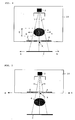
- FIG. 1 shows a first embodiment in plan, in which by means of an object-dependent adjusted aperture, the scattered radiation is reduced.
- FIG. 1 shows schematically a device 1, by means of which an object 4 is transilluminated in order to produce on a receiving means 3 an image of the object 4.
- the device 1 is, for example, an industrial or medical X-ray system, which illuminates a technical object 4, or a patient, and generates the image on an X-ray film or an X-ray plate 3.
- the X-ray source 2 is an X-ray tube.
- the X-ray source 2 which is arranged in a schematically illustrated housing, generates X-rays, their cones or otherwise differently shaped outline with the boundary lines 5 in the Figure is indicated.
- the x-ray source 2 is located, for example, in a housing 10, which is closed by the aperture 6 to the object 4 out.
- the panel can also be arranged separately, housing independent.
- the diaphragm 6 has an opening 9, through which a part of the X-rays can escape through the aperture from the housing 10, while the rest of the X-rays is prevented by the diaphragm 6 from exiting the housing.
- the object is placed so that it can be detected by the entire cone of rays, as it exits from the source 2 and is indicated by the lines 5.
- the radiation emerging from the source 2 can be limited in a known manner by an only indicated collimator 2 ';
- the lines 5 represent the already limited radiation, which may also extend only over a part of the object 4, if only this part is to be imaged or only this part is moved relative to the beam.
- the opening 9 of the aperture 6 shown in section is set in any case in the aperture dimension, which corresponds to the direction of movement, as a function of the size of the object 4.
- the width b of the aperture 9 is set, which is in the direction of movement (arrow A).
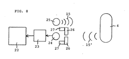
- FIG. 1 schematically represented by two sensors 8, which measure the object 4, for example, contactless by an ultrasonic measurement or an optical measurement. Sensors may also be provided which contact the object to accommodate its dimension for the aperture setting.
- the size of the Aperture 9 determined and adjusted for example by servomotors 7, which are operated by the controller 11.
- One in the recording situation of FIG. 1 dimension of interest is the width B of the object, which is traversed by the relative movement in the direction of an arrow A.
- the width b of the slot-shaped aperture opening of the diaphragm 6 is set in the present example.
- the width b of the aperture is x times smaller than the width B of the object, where x is in the range of 10 to 100,000, so that the slot width is thus 10 times to 100,000 times less than the width B of the object.
- the diaphragm aperture can also be chosen to be proportional to the width B of the part of the object. Further, preferably, the height of the slot opening of the aperture 6 corresponding to the height of the object 4, that is, the extension perpendicular to the plane of the object 4, set.
- the same divider can be used as in the width setting, so that the slot height is also 10 times smaller to 100,000 times smaller than the height of the object 4.
- the object 4 is then imaged accordingly by a limited by the object size dependent aperture X-ray, in which case the object and the imaging means or the X-ray plate 3 are moved together several times along the stationary and dimmed X-ray source 2, in each case correspondingly displaced in height, so that the image is produced strip by strip.
- the object and the imaging means or the X-ray plate 3 are moved together several times along the stationary and dimmed X-ray source 2, in each case correspondingly displaced in height, so that the image is produced strip by strip.
- FIG. 2 schematically shows a view of the diaphragm 6, wherein this according to FIG. 1 a slit with the slot 9 is.
- This slot 9 can be adjusted in height h and its width b by means of movable diaphragm elements 12 and 13, which are displaceable relative to one another. This is done by the in FIG. 1 indicated actuating means, which may be motor, pneumatic or hydraulic actuating means.
- Figure 3 shows a corresponding sectional view through the aperture 6 of FIG. 2 , wherein like elements are provided with the same reference numerals.
- the diaphragm can also be set differently in its depth t, for which purpose preferably also the depth T of the object is measured. A depth adjustment can take place in that several of the apertures are connected in series, as in FIG. 3 with a further aperture 6 'is merely indicated.
- the use according to the invention of the diaphragm for reducing the stray radiation is possible for the entire spectrum of electromagnetic radiation.
- the highest possible proportionality e.g. between 1: 10,000 to 1: 100,000.
- the width of the aperture of the aperture to the micrometer range desirable.
- the optimum ratio diaphragm: object can only be realized technically complex, e.g. just for apertures in the range of 10 to 100 microns. In this case, a lower proportionality is decreased, e.g. 1:10 or 1:50.
- FIG. 4 shows a further embodiment of the invention, wherein like reference numerals as used in the previous figures denote like elements.
- the aperture also shown cut is between the object 4 and the receiving means 3 arranged.
- the object 4 and the imaging means 3 are moved past the stationary diaphragm 6 and the stationary X-ray source according to the arrows A.
- this passing movement takes place several times with different shifted height positions of diaphragm and object.
- the means 7, 8 and 11 are no longer shown, but are also present in the device.
- the dimension of the diaphragm is also set here, which corresponds to the relative movement, in the present case again the width b proportional to the width of the object 4.
- the beam 5 exits from the source 2, possibly through a collimator.
- FIG. 5 shows a further embodiment in which in turn the same elements are provided with the same reference numerals and the means 7, 8 and 11 are not shown, but the X-ray source 2 and the diaphragm 6 according to the arrow A on the fixed object and the stationary imaging means 3 are moved past , Again, the image on the imaging means 3 line by line corresponding to the height of the slot of the diaphragm 6 can be generated.
- FIG. 6 shows a corresponding embodiment, wherein, however, the diaphragm between the object 4 and the imaging means 3 is arranged. Also the aperture of the Figures 5 and 6 are each set in their slot width b according to the direction of the process of the diaphragm.
- FIG. 7 shows a further embodiment in which two apertures 6 and 16 are provided with the openings 9 and 19, wherein the one aperture between the X-ray source and the object and the other diaphragm between the object and the imaging means 3 is provided.
- the apertures are moved synchronously with the X-ray source 2 in order to scan the object line by line.
- the aperture 9 is doing again in the width b set object-dependent, preferably this also takes place at the aperture 19th
- a preferred application of the invention is in the medical X-ray technology and in the industrial X-ray technology for testing materials.
- the tripod is a commercially available multistat with film cassettes or storage foils. On the tripod a panel with control is installed later.
- the reduction of the scattered radiation can be calculated as a first approximation as a proportion, which results from the total irradiated area without aperture to the passage area of the aperture.
- the number of passes is usually 1.
- the time required for the linear movement in direction A depends on the size of the object and is practicable between 0.1 and 10 seconds.
Abstract
Description
Die Erfindung betrifft ein Verfahren gemäss Oberbegriff des Anspruchs 1 sowie eine Vorrichtung gemäss Oberbegriff des Anspruchs 9.The invention relates to a method according to the preamble of
In der Fototechnik sind bewegte Blenden (shutter, Verschlussblenden) zur Dosierung der Lichtmenge bekannt, wobei z.B. die Breite der Blende zur Variation der Lichtmenge verschieden eingestellt werden kann.In photographic technology, moving shutters (shutter, shutter) for metering the amount of light are known, e.g. the width of the aperture for varying the amount of light can be set differently.
In der Radiologie sind Blenden als Kollimatoren bekannt, die mit konstanten Dimensionen zur Reduktion der erzeugten Strahlendosis dienen aber auch gemäss
Es ist Aufgabe der vorliegenden Erfindung die Bildqualität zu verbessern.It is an object of the present invention to improve the image quality.
Bei einem Verfahren der eingangs genannten Art wird dies durch die kennzeichnenden Merkmale des Anspruchs 1 erreicht. Bei einer Vorrichtung der eingangs genannten Art durch die kennzeichnenden Merkmale des Anspruchs 9.In a method of the type mentioned, this is achieved by the characterizing features of
Dadurch, dass eine Blende mit objektgrössenabhängiger Blendenöffnung eingesetzt wird kann die Streustrahlung besonders gut verringert werden, was die Bildqualität erhöht. Es hat sich bei der Röntgenfotografie gezeigt, dass die objektgrössenabhängige Blende zu schärferen Aufnahmen führt, die eine bessere Interpretation des Bildes des Objektes erlauben.The fact that a screen with object size-dependent aperture is used, the scattered radiation can be particularly well reduced, which increases the image quality. It has been shown in X-ray photography that the object size-dependent aperture leads to sharper images, which allow a better interpretation of the image of the object.
Im Folgenden werden Ausführungsbeispiele der Erfindung anhand der Beschreibung und der Zeichnungen näher erläutert. Dabei zeigt
-
Figur 1 -
Figur 2Figur 1 -
Figur 3Figur 2 -
Figur 4Figur 1 -
Figur 5 -
Figur 6 -
Figur 7
-
FIG. 1 a schematic view of the inventive approach or a device for scanning an object; -
FIG. 2 schematically a plan view of the diaphragm ofFIG. 1 ; -
FIG. 3 a sectional view taken along the line AA ofFIG. 2 as well as a variant of the aperture; -
FIG. 4 a schematic view of a modification of the procedure or the device ofFIG. 1 ; -
FIG. 5 another embodiment; -
FIG. 6 a further embodiment of the device; and -
FIG. 7 an embodiment with two panels.
Streustrahlung, die z.B. bei Abbildung von Objekten durch Lichtstrahlen oder Röntgenstrahlen immer entsteht, ist auf dem Bild kontrastmindernd da sie die gewünschte optimale Konturschärfe des Objektes verringert. Streustrahlung bildet sich bei der Abbildung von Objekten durch ojektbezogene Reflektionen oder durch ionisierende Strahlung, die das Objekt durchdringt. Entsprechend entstehende unscharfe Konturen sind die Ursache für einen schlechteren Kontrast der Abbildung des Objektes und können bei der Auswertung der Abbildung zu unschlüssigen Folgerungen führen, da mangels Aussagekraft der Abbildung eine gesicherte Aussage über das Objekt verunmöglicht wird.
Die erfindungsgemässe Anwendung der Blende zur Reduktion der Streustrahlung ist für das ganze Spektrum der elektromagnetischen Strahlung möglich. Je kleiner das abzubildende Objekt ist, um so kleiner sollte die Blende ausgeführt sein, wobei das Verhältnis der Proportionen (Blende zu Objekt) wie gesagt von 1:10 bis 1: 100'000 betragen kann. Um eine möglichst gute Streustrahlungsreduktion zu erreichen, wird eine möglichst hohe Proportionalität, z.B. zwischen 1:10'000 bis 1:100'000 bevorzugt. Dabei ist z.B. die Breite der Öffnung der Blende bis in den Mikrometerbereich erstrebenswert. Vor allem bei sehr kleinen Objekten, z.B. kleiner als 1 mm, kann das optimale Verhältnis Blende:Objekt aber nur technisch aufwändig realisiert werden, z.B. eben für Blendenöffnungen im Bereich von 10 bis 100 Mikrometern. In diesem Fall wird zu einer geringeren Proportionalität zurückgegangen, z.B. 1:10 oder 1:50.The use according to the invention of the diaphragm for reducing the stray radiation is possible for the entire spectrum of electromagnetic radiation. The smaller the object to be imaged, the smaller the aperture should be, whereby the ratio of proportions (aperture to object) can be from 1:10 to 1: 100,000. In order to achieve the best possible scattered radiation reduction, the highest possible proportionality, e.g. between 1: 10,000 to 1: 100,000. In this case, e.g. the width of the aperture of the aperture to the micrometer range desirable. Especially for very small objects, e.g. smaller than 1 mm, the optimum ratio diaphragm: object can only be realized technically complex, e.g. just for apertures in the range of 10 to 100 microns. In this case, a lower proportionality is decreased, e.g. 1:10 or 1:50.
Eine bevorzugte Anwendung der Erfindung liegt in der medizinischen Röntgentechnik und in der industriellen Röntgentechnik zur Prüfung von Materialien.A preferred application of the invention is in the medical X-ray technology and in the industrial X-ray technology for testing materials.
Im Folgenden werden Beispiele für Röntgenaufnahmen mit der objektabhängig verstellbaren Blende gegeben.The following are examples of X-rays with the object-dependent adjustable aperture.
Als Stativ dient ein handelsübliches Multistat mit Filmkassetten oder Speicherfolien. Am Stativ wird nachträglich eine Blende mit Steuerung eingebaut. Die Reduktion der Streustrahlung kann so in erster Näherung als Proportion berechnet werden, die sich aus der gesamten Bestrahlten Fläche ohne Blende zu der Durchlassfläche der Blende ergibt.The tripod is a commercially available multistat with film cassettes or storage foils. On the tripod a panel with control is installed later. The reduction of the scattered radiation can be calculated as a first approximation as a proportion, which results from the total irradiated area without aperture to the passage area of the aperture.
Ohne Blende entstehen 100 % Streustrahlung; mit Blende erreicht man eine Reduktion der Streustrahlung um 100 % -0,2325 % = 99,7675 %.Without aperture, 100% scattered radiation is produced; With Aperture a reduction of the scattered radiation by 100% -0.2325% = 99.7675% can be achieved.
Mit dieser Blende reduziert sich die Streustrahlung um 100 % -0,001163 % = 99,9987 %.With this aperture, the scattered radiation is reduced by 100% -0.001163% = 99.9987%.
Die Anzahl Durchläufe ist in der Regel 1.The number of passes is usually 1.
Der Zeitbedarf für die lineare Bewegung in Richtung A ist abhängig von der Grösse des Objektes und beträgt praktikabel zwischen 0,1 und 10 Sekunden.The time required for the linear movement in direction A depends on the size of the object and is practicable between 0.1 and 10 seconds.
Claims (13)
- Method for the recording of an object (4) by imaging by means of an X-ray radiation source (2) onto a recording means (3), particularly a film, wherein the object is roentgenised and is recorded continuously or discontinuously section by section during the recording, by means of at least one aperture (6) and a relative movement of the object on the one hand and aperture and recording means and optionally X-ray radiation source on the other hand, wherein the size of the aperture opening (9, 19) is adjusted depending on the object size in at least the dimension of the aperture opening lying in the direction of the relative movement, characterized in that the object volume or the surface of the object facing the X-ray radiation or only a dimension of this surface is taken into account as object size, and in that the object size is detected by means of a detection installation having mechanical and/or optical sensors or ultrasonic sensors (8) for the detection of the object volume or of at least one object dimension, wherein the aperture opening (9, 19) is particularly adjusted before or during each recording.
- Method according to claim 1, characterized in that the X-rays (5) are limited in front of the aperture by means of at least one collimator (2').
- Method according to one of the claims 1 or 2, characterized in that the object (4) and the recording means (3) are passed by the stationary X-ray radiation source (2) and the stationary aperture (6), wherein the aperture (6) is arranged between the X-ray radiation source (2) and the object (4) or wherein the aperture (6) is arranged between the object (4) and the recording means.
- Method according to one of the claims 1 or 2, characterized in that the X-ray radiation source (2) and the aperture (6) are passed by the stationary object (4) and the stationary recording means (3), wherein the aperture (6) is arranged between the X-ray radiation source (2) and the object (4) or wherein the aperture (6) is arranged between the object (4) and the recording means (3), or wherein a first aperture (6) is arranged between the radiation source (3) and the object (4) and a second aperture (16) between the object (4) and the recoding means (3).
- Method according to one of the claims 1 to 4, characterized in that the relative movement occurs in the direction of the width B of the object and the width b of the aperture opening is adjusted depending on the object size and optionally the height h of the aperture opening is additionally adjusted.
- Method according to one of the claims 1 to 4, characterized in that the relative movement occurs in the direction of the height of the object and the height h of the aperture opening is adjusted depending on the object height.
- Method according to one of the claims 5 or 6, characterized in that the thickness t of the aperture is additionally adjusted, particularly depending on the object thickness T.
- Method according to one of the claims 1 to 7, characterized in that the aperture opening dimension is adjusted in a range of 1:10 to 1:100000 with respect to the object dimension, preferably in a range of 1:100 to 1:100000, further preferred in a range of 1:1000 to 1:100000 and further preferred in a range of 1:10000 to 1:100000.
- Device for the recording of an object onto recording means (3) by means of an X-ray radiation source (2), wherein the device comprises at least an aperture (6) and movement means for the relative movement between the aperture (6) and the object (4), and wherein an adjustment installation (7, 11) is provided for the adjustment of at least one aperture opening dimension and a detection installation (8, 11) is provided for detecting at least one object dimension and wherein the adjustment installation is connected to the detection installation in such a way that at least an aperture opening dimension is adjustable depending on the at least one detected object dimension, wherein the at least one adjustable aperture opening dimension is adjustable in the direction of the relative movement, characterized in that the object volume or the surface of the object facing the X-ray radiation or only a dimension of this surface can be taken into account as object size, and in that the detection installation has mechanical and/or optical sensors or ultrasonic sensors (8) for the detection of the object volume or of at least one object dimension.
- Device according to claim 9, characterized in that it comprises an X-ray radiation source (2), the ray of which is limited by means of at least one collimator (2').
- Device according to claim 9 or 10, characterized in that it comprises an object carrier (4') and in that the object carrier on the one hand and the aperture (6) on the other hand are movable relatively to each other by means of the movement means (7, 11).
- Device according to claim 11, characterized in that the X-ray radiation source (2) and the aperture (6) are secured to the device, and in that for this, the object carrier (4') and the recording means (3) are movably arranged for the performance of the relative movement, wherein the aperture (6) is arranged between the X-ray radiation source (2) and the object carrier (4'), or wherein the aperture (6) is arranged between the object carrier and the recording means (3).
- Device according to claim 11, characterized in that the object carrier and the recording means (3) are secured to the device and in that for this, the X-ray radiation source (2) and the aperture (6) are movably arranged for the performance of the relative movement, wherein the aperture (6) is arranged between the X-ray radiation source (2) and the object carrier or wherein the aperture (6) is arranged between the object carrier and the recording means (3) or wherein a first aperture (6) is arranged between the X-ray radiation source (2) and the object carrier and a second aperture (16) which is motion-coupled with the first aperture is arranged between the object carrier and the recording means.
Priority Applications (1)
| Application Number | Priority Date | Filing Date | Title |
|---|---|---|---|
| EP02783377A EP1446810B1 (en) | 2001-11-22 | 2002-11-15 | Method and device for the recording of objects |
Applications Claiming Priority (4)
| Application Number | Priority Date | Filing Date | Title |
|---|---|---|---|
| EP01127371A EP1315177A1 (en) | 2001-11-22 | 2001-11-22 | Method and device for object imaging |
| EP01127371 | 2001-11-22 | ||
| EP02783377A EP1446810B1 (en) | 2001-11-22 | 2002-11-15 | Method and device for the recording of objects |
| PCT/IB2002/004765 WO2003044807A1 (en) | 2001-11-22 | 2002-11-15 | Method and device for the recording of objects |
Publications (2)
| Publication Number | Publication Date |
|---|---|
| EP1446810A1 EP1446810A1 (en) | 2004-08-18 |
| EP1446810B1 true EP1446810B1 (en) | 2010-09-01 |
Family
ID=8179271
Family Applications (2)
| Application Number | Title | Priority Date | Filing Date |
|---|---|---|---|
| EP01127371A Withdrawn EP1315177A1 (en) | 2001-11-22 | 2001-11-22 | Method and device for object imaging |
| EP02783377A Expired - Lifetime EP1446810B1 (en) | 2001-11-22 | 2002-11-15 | Method and device for the recording of objects |
Family Applications Before (1)
| Application Number | Title | Priority Date | Filing Date |
|---|---|---|---|
| EP01127371A Withdrawn EP1315177A1 (en) | 2001-11-22 | 2001-11-22 | Method and device for object imaging |
Country Status (6)
| Country | Link |
|---|---|
| US (1) | US7372945B2 (en) |
| EP (2) | EP1315177A1 (en) |
| AT (1) | ATE479994T1 (en) |
| AU (1) | AU2002347443A1 (en) |
| DE (1) | DE50214635D1 (en) |
| WO (1) | WO2003044807A1 (en) |
Families Citing this family (1)
| Publication number | Priority date | Publication date | Assignee | Title |
|---|---|---|---|---|
| US9566040B2 (en) * | 2014-05-14 | 2017-02-14 | Swissray Asia Healthcare Co., Ltd. | Automatic collimator adjustment device with depth camera and method for medical treatment equipment |
Family Cites Families (15)
| Publication number | Priority date | Publication date | Assignee | Title |
|---|---|---|---|---|
| US3518435A (en) * | 1967-11-24 | 1970-06-30 | Philips Corp | Automatic x-radiation collimating apparatus responsive to film cassette size |
| SU591239A1 (en) * | 1976-01-24 | 1978-02-05 | Куйбышевский Ордена Трудового Красного Знамени Авиационный Институт Им. Академика С.П.Королева | Ultrasonic collimator |
| US4122350A (en) * | 1977-11-21 | 1978-10-24 | Julius Lipthay | Adjustable collimator for mammography |
| US4603427A (en) * | 1983-12-16 | 1986-07-29 | Alpern Michael C | Collimator in a panoramic dental X-ray apparatus |
| DE3500812A1 (en) | 1985-01-11 | 1986-07-17 | Siemens AG, 1000 Berlin und 8000 München | X-RAY DIAGNOSTIC DEVICE WITH SEMI-TRANSPARENT PANEL |
| CA1244971A (en) * | 1985-11-14 | 1988-11-15 | Shih-Ping Wang | X-ray radiography method and system |
| DE4210120C1 (en) * | 1992-03-27 | 1993-08-05 | Siemens Ag, 8000 Muenchen, De | X=ray appts. for peripheral angiography - calculates relative positioning of appts. and patient support using data derived from patient |
| US5244136A (en) * | 1992-04-03 | 1993-09-14 | Vincent Collaso | Expandable water-proof pouch |
| US5224136A (en) | 1992-06-30 | 1993-06-29 | General Electric Company | Helical scanning computed tomography apparatus with constrained tracking of the x-ray source |
| US5627869A (en) * | 1995-11-22 | 1997-05-06 | Thermotrex Corporation | Mammography apparatus with proportional collimation |
| US5818902A (en) * | 1996-03-01 | 1998-10-06 | Elekta Ab | Intensity modulated arc therapy with dynamic multi-leaf collimation |
| US6502984B2 (en) * | 1997-01-17 | 2003-01-07 | Canon Kabushiki Kaisha | Radiographic apparatus |
| US6055295A (en) * | 1998-01-29 | 2000-04-25 | Siemens Corporate Research, Inc. | Method and apparatus for automatic collimation in x-ray peripheral imaging |
| US6496557B2 (en) * | 2000-02-09 | 2002-12-17 | Hologic, Inc. | Two-dimensional slot x-ray bone densitometry, radiography and tomography |
| DE102005006895B4 (en) * | 2005-02-15 | 2010-11-18 | Siemens Ag | X-ray diagnostic device and method for its regulation |
-
2001
- 2001-11-22 EP EP01127371A patent/EP1315177A1/en not_active Withdrawn
-
2002
- 2002-11-15 AU AU2002347443A patent/AU2002347443A1/en not_active Abandoned
- 2002-11-15 DE DE50214635T patent/DE50214635D1/en not_active Expired - Lifetime
- 2002-11-15 AT AT02783377T patent/ATE479994T1/en not_active IP Right Cessation
- 2002-11-15 WO PCT/IB2002/004765 patent/WO2003044807A1/en not_active Application Discontinuation
- 2002-11-15 US US10/496,038 patent/US7372945B2/en not_active Expired - Fee Related
- 2002-11-15 EP EP02783377A patent/EP1446810B1/en not_active Expired - Lifetime
Also Published As
| Publication number | Publication date |
|---|---|
| DE50214635D1 (en) | 2010-10-14 |
| EP1315177A1 (en) | 2003-05-28 |
| EP1446810A1 (en) | 2004-08-18 |
| WO2003044807A1 (en) | 2003-05-30 |
| US7372945B2 (en) | 2008-05-13 |
| US20050008122A1 (en) | 2005-01-13 |
| AU2002347443A1 (en) | 2003-06-10 |
| ATE479994T1 (en) | 2010-09-15 |
Similar Documents
| Publication | Publication Date | Title |
|---|---|---|
| DE2732073C2 (en) | Computed tomograph | |
| DE602004012080T2 (en) | IDENTIFYING IONIZING RADIATION TO DUAL ENERGY SCANNING BASIS | |
| DE19527518B4 (en) | X-ray tube current modulation during computed tomography scanning | |
| DE102008049708B4 (en) | Aperture and diaphragm device for the targeted influence of X-radiation | |
| DE60204764T2 (en) | METHOD AND DEVICE FOR MEASURING THE POSITION, FORM, SIZE AND INTENSITY DISTRIBUTION OF AN EFFECTIVE X-RAY FILM FOCUS | |
| DE112006003039T5 (en) | Method and arrangement for X-ray imaging | |
| DE2741958C2 (en) | ||
| DE10228154A1 (en) | Digital x-ray imaging device with raster function | |
| DE69938096T2 (en) | Beam scattering measuring device with detection of the continuous beam energy | |
| DE2720840A1 (en) | COLLIMATOR FOR REDUCING RADIATION EXPOSURE AND IMPROVING THE RESOLUTION OF RADIATION DIAGNOSTIC SHEET DISPLAYS | |
| DE19651722A1 (en) | Automatic exposure setting method for panorama or tomographic radiography device | |
| DE3928282A1 (en) | X-RAY RECEIVING DEVICE | |
| DE2744226C2 (en) | Layering device for the production of transverse layer images | |
| CH616581A5 (en) | ||
| DE2548531C2 (en) | ||
| DE10320862B4 (en) | Method for automatically adjusting a diaphragm, as well as X-ray system | |
| DE2831311C2 (en) | Device for determining internal body structures by means of scattered radiation | |
| CH630176A5 (en) | Method of producing a tomogram and device for tomographically investigating an object | |
| DE10164245A1 (en) | Gap compensating method in multi-plate volumetric CT scanners and associated apparatus | |
| EP1446810B1 (en) | Method and device for the recording of objects | |
| DE2623965C3 (en) | Computer tomograph | |
| DE2832271A1 (en) | ROENTGEN DIAGNOSTIC DEVICE FOR THE PRODUCTION OF TRANSVERSAL SLAT IMAGES | |
| DE102007020642A1 (en) | X-ray device and sensor unit for an X-ray device | |
| DE3121324A1 (en) | TOMOSYNTHESIS DEVICE | |
| DE10127267B4 (en) | Medical imaging X-ray machine |
Legal Events
| Date | Code | Title | Description |
|---|---|---|---|
| PUAI | Public reference made under article 153(3) epc to a published international application that has entered the european phase |
Free format text: ORIGINAL CODE: 0009012 |
|
| 17P | Request for examination filed |
Effective date: 20040517 |
|
| AK | Designated contracting states |
Kind code of ref document: A1 Designated state(s): AT BE BG CH CY CZ DE DK EE ES FI FR GB GR IE IT LI LU MC NL PT SE SK TR |
|
| AX | Request for extension of the european patent |
Extension state: AL LT LV MK RO SI |
|
| RAP1 | Party data changed (applicant data changed or rights of an application transferred) |
Owner name: TECNOSTORE AG |
|
| RIN1 | Information on inventor provided before grant (corrected) |
Inventor name: GEISSER, ALBERT Inventor name: KEZMANN, BRUNO RUDOLF |
|
| 17Q | First examination report despatched |
Effective date: 20071122 |
|
| GRAP | Despatch of communication of intention to grant a patent |
Free format text: ORIGINAL CODE: EPIDOSNIGR1 |
|
| GRAS | Grant fee paid |
Free format text: ORIGINAL CODE: EPIDOSNIGR3 |
|
| GRAA | (expected) grant |
Free format text: ORIGINAL CODE: 0009210 |
|
| AK | Designated contracting states |
Kind code of ref document: B1 Designated state(s): AT BE BG CH CY CZ DE DK EE ES FI FR GB GR IE IT LI LU MC NL PT SE SK TR |
|
| REG | Reference to a national code |
Ref country code: GB Ref legal event code: FG4D Free format text: NOT ENGLISH |
|
| REG | Reference to a national code |
Ref country code: CH Ref legal event code: NV Representative=s name: E. BLUM & CO. AG PATENT- UND MARKENANWAELTE VSP Ref country code: CH Ref legal event code: EP |
|
| REG | Reference to a national code |
Ref country code: IE Ref legal event code: FG4D Free format text: LANGUAGE OF EP DOCUMENT: GERMAN |
|
| REF | Corresponds to: |
Ref document number: 50214635 Country of ref document: DE Date of ref document: 20101014 Kind code of ref document: P |
|
| REG | Reference to a national code |
Ref country code: NL Ref legal event code: VDEP Effective date: 20100901 |
|
| PG25 | Lapsed in a contracting state [announced via postgrant information from national office to epo] |
Ref country code: FI Free format text: LAPSE BECAUSE OF FAILURE TO SUBMIT A TRANSLATION OF THE DESCRIPTION OR TO PAY THE FEE WITHIN THE PRESCRIBED TIME-LIMIT Effective date: 20100901 |
|
| PG25 | Lapsed in a contracting state [announced via postgrant information from national office to epo] |
Ref country code: CY Free format text: LAPSE BECAUSE OF FAILURE TO SUBMIT A TRANSLATION OF THE DESCRIPTION OR TO PAY THE FEE WITHIN THE PRESCRIBED TIME-LIMIT Effective date: 20100901 |
|
| PGFP | Annual fee paid to national office [announced via postgrant information from national office to epo] |
Ref country code: CH Payment date: 20101104 Year of fee payment: 9 Ref country code: DE Payment date: 20101119 Year of fee payment: 9 |
|
| REG | Reference to a national code |
Ref country code: IE Ref legal event code: FD4D |
|
| PG25 | Lapsed in a contracting state [announced via postgrant information from national office to epo] |
Ref country code: GR Free format text: LAPSE BECAUSE OF FAILURE TO SUBMIT A TRANSLATION OF THE DESCRIPTION OR TO PAY THE FEE WITHIN THE PRESCRIBED TIME-LIMIT Effective date: 20101202 Ref country code: SE Free format text: LAPSE BECAUSE OF FAILURE TO SUBMIT A TRANSLATION OF THE DESCRIPTION OR TO PAY THE FEE WITHIN THE PRESCRIBED TIME-LIMIT Effective date: 20100901 Ref country code: NL Free format text: LAPSE BECAUSE OF FAILURE TO SUBMIT A TRANSLATION OF THE DESCRIPTION OR TO PAY THE FEE WITHIN THE PRESCRIBED TIME-LIMIT Effective date: 20100901 |
|
| PG25 | Lapsed in a contracting state [announced via postgrant information from national office to epo] |
Ref country code: IE Free format text: LAPSE BECAUSE OF FAILURE TO SUBMIT A TRANSLATION OF THE DESCRIPTION OR TO PAY THE FEE WITHIN THE PRESCRIBED TIME-LIMIT Effective date: 20100901 |
|
| BERE | Be: lapsed |
Owner name: TECNOSTORE A.G. Effective date: 20101130 |
|
| PG25 | Lapsed in a contracting state [announced via postgrant information from national office to epo] |
Ref country code: CZ Free format text: LAPSE BECAUSE OF FAILURE TO SUBMIT A TRANSLATION OF THE DESCRIPTION OR TO PAY THE FEE WITHIN THE PRESCRIBED TIME-LIMIT Effective date: 20100901 Ref country code: PT Free format text: LAPSE BECAUSE OF FAILURE TO SUBMIT A TRANSLATION OF THE DESCRIPTION OR TO PAY THE FEE WITHIN THE PRESCRIBED TIME-LIMIT Effective date: 20110103 Ref country code: SK Free format text: LAPSE BECAUSE OF FAILURE TO SUBMIT A TRANSLATION OF THE DESCRIPTION OR TO PAY THE FEE WITHIN THE PRESCRIBED TIME-LIMIT Effective date: 20100901 Ref country code: EE Free format text: LAPSE BECAUSE OF FAILURE TO SUBMIT A TRANSLATION OF THE DESCRIPTION OR TO PAY THE FEE WITHIN THE PRESCRIBED TIME-LIMIT Effective date: 20100901 Ref country code: IT Free format text: LAPSE BECAUSE OF FAILURE TO SUBMIT A TRANSLATION OF THE DESCRIPTION OR TO PAY THE FEE WITHIN THE PRESCRIBED TIME-LIMIT Effective date: 20100901 |
|
| PG25 | Lapsed in a contracting state [announced via postgrant information from national office to epo] |
Ref country code: MC Free format text: LAPSE BECAUSE OF NON-PAYMENT OF DUE FEES Effective date: 20101130 Ref country code: ES Free format text: LAPSE BECAUSE OF FAILURE TO SUBMIT A TRANSLATION OF THE DESCRIPTION OR TO PAY THE FEE WITHIN THE PRESCRIBED TIME-LIMIT Effective date: 20101212 |
|
| PLBE | No opposition filed within time limit |
Free format text: ORIGINAL CODE: 0009261 |
|
| STAA | Information on the status of an ep patent application or granted ep patent |
Free format text: STATUS: NO OPPOSITION FILED WITHIN TIME LIMIT |
|
| 26N | No opposition filed |
Effective date: 20110606 |
|
| REG | Reference to a national code |
Ref country code: FR Ref legal event code: ST Effective date: 20110801 |
|
| GBPC | Gb: european patent ceased through non-payment of renewal fee |
Effective date: 20101201 |
|
| PG25 | Lapsed in a contracting state [announced via postgrant information from national office to epo] |
Ref country code: DK Free format text: LAPSE BECAUSE OF FAILURE TO SUBMIT A TRANSLATION OF THE DESCRIPTION OR TO PAY THE FEE WITHIN THE PRESCRIBED TIME-LIMIT Effective date: 20100901 Ref country code: BE Free format text: LAPSE BECAUSE OF NON-PAYMENT OF DUE FEES Effective date: 20101130 |
|
| REG | Reference to a national code |
Ref country code: DE Ref legal event code: R097 Ref document number: 50214635 Country of ref document: DE Effective date: 20110606 |
|
| PG25 | Lapsed in a contracting state [announced via postgrant information from national office to epo] |
Ref country code: FR Free format text: LAPSE BECAUSE OF NON-PAYMENT OF DUE FEES Effective date: 20101130 |
|
| PG25 | Lapsed in a contracting state [announced via postgrant information from national office to epo] |
Ref country code: GB Free format text: LAPSE BECAUSE OF NON-PAYMENT OF DUE FEES Effective date: 20101201 |
|
| REG | Reference to a national code |
Ref country code: AT Ref legal event code: MM01 Ref document number: 479994 Country of ref document: AT Kind code of ref document: T Effective date: 20101115 |
|
| PG25 | Lapsed in a contracting state [announced via postgrant information from national office to epo] |
Ref country code: AT Free format text: LAPSE BECAUSE OF NON-PAYMENT OF DUE FEES Effective date: 20101115 |
|
| REG | Reference to a national code |
Ref country code: CH Ref legal event code: PL |
|
| PG25 | Lapsed in a contracting state [announced via postgrant information from national office to epo] |
Ref country code: LI Free format text: LAPSE BECAUSE OF NON-PAYMENT OF DUE FEES Effective date: 20111130 Ref country code: CH Free format text: LAPSE BECAUSE OF NON-PAYMENT OF DUE FEES Effective date: 20111130 |
|
| REG | Reference to a national code |
Ref country code: DE Ref legal event code: R119 Ref document number: 50214635 Country of ref document: DE Effective date: 20120601 |
|
| PG25 | Lapsed in a contracting state [announced via postgrant information from national office to epo] |
Ref country code: BG Free format text: LAPSE BECAUSE OF FAILURE TO SUBMIT A TRANSLATION OF THE DESCRIPTION OR TO PAY THE FEE WITHIN THE PRESCRIBED TIME-LIMIT Effective date: 20100901 Ref country code: LU Free format text: LAPSE BECAUSE OF NON-PAYMENT OF DUE FEES Effective date: 20101115 |
|
| PG25 | Lapsed in a contracting state [announced via postgrant information from national office to epo] |
Ref country code: TR Free format text: LAPSE BECAUSE OF FAILURE TO SUBMIT A TRANSLATION OF THE DESCRIPTION OR TO PAY THE FEE WITHIN THE PRESCRIBED TIME-LIMIT Effective date: 20100901 |
|
| PG25 | Lapsed in a contracting state [announced via postgrant information from national office to epo] |
Ref country code: DE Free format text: LAPSE BECAUSE OF NON-PAYMENT OF DUE FEES Effective date: 20120601 |
|
| PG25 | Lapsed in a contracting state [announced via postgrant information from national office to epo] |
Ref country code: BG Free format text: LAPSE BECAUSE OF FAILURE TO SUBMIT A TRANSLATION OF THE DESCRIPTION OR TO PAY THE FEE WITHIN THE PRESCRIBED TIME-LIMIT Effective date: 20101201 |