EP1446216B1 - Sorptionsrotor - Google Patents
Sorptionsrotor Download PDFInfo
- Publication number
- EP1446216B1 EP1446216B1 EP02787753A EP02787753A EP1446216B1 EP 1446216 B1 EP1446216 B1 EP 1446216B1 EP 02787753 A EP02787753 A EP 02787753A EP 02787753 A EP02787753 A EP 02787753A EP 1446216 B1 EP1446216 B1 EP 1446216B1
- Authority
- EP
- European Patent Office
- Prior art keywords
- material matrix
- sol
- infiltrated
- sorption rotor
- gel system
- Prior art date
- Legal status (The legal status is an assumption and is not a legal conclusion. Google has not performed a legal analysis and makes no representation as to the accuracy of the status listed.)
- Expired - Lifetime
Links
- 238000001179 sorption measurement Methods 0.000 title claims abstract description 63
- 239000011159 matrix material Substances 0.000 claims abstract description 67
- 229920002678 cellulose Polymers 0.000 claims abstract description 31
- 239000001913 cellulose Substances 0.000 claims abstract description 31
- 239000007788 liquid Substances 0.000 claims abstract description 13
- 229910010293 ceramic material Inorganic materials 0.000 claims abstract description 6
- 239000000463 material Substances 0.000 claims description 59
- KWGKDLIKAYFUFQ-UHFFFAOYSA-M lithium chloride Chemical compound [Li+].[Cl-] KWGKDLIKAYFUFQ-UHFFFAOYSA-M 0.000 claims description 20
- 238000000034 method Methods 0.000 claims description 20
- 239000000919 ceramic Substances 0.000 claims description 16
- 239000007787 solid Substances 0.000 claims description 10
- 239000011148 porous material Substances 0.000 claims description 8
- 239000002131 composite material Substances 0.000 claims description 7
- 229910052799 carbon Inorganic materials 0.000 claims description 6
- 230000008595 infiltration Effects 0.000 claims description 6
- 238000001764 infiltration Methods 0.000 claims description 6
- OKTJSMMVPCPJKN-UHFFFAOYSA-N Carbon Chemical compound [C] OKTJSMMVPCPJKN-UHFFFAOYSA-N 0.000 claims description 5
- 230000000274 adsorptive effect Effects 0.000 claims description 5
- 238000001035 drying Methods 0.000 claims description 5
- 229910052710 silicon Inorganic materials 0.000 claims description 5
- 239000010703 silicon Substances 0.000 claims description 5
- XLYOFNOQVPJJNP-UHFFFAOYSA-N water Substances O XLYOFNOQVPJJNP-UHFFFAOYSA-N 0.000 claims description 5
- 238000005516 engineering process Methods 0.000 claims description 4
- 239000010457 zeolite Substances 0.000 claims description 4
- 239000011261 inert gas Substances 0.000 claims description 3
- VYPSYNLAJGMNEJ-UHFFFAOYSA-N Silicium dioxide Chemical compound O=[Si]=O VYPSYNLAJGMNEJ-UHFFFAOYSA-N 0.000 claims 4
- GWEVSGVZZGPLCZ-UHFFFAOYSA-N Titan oxide Chemical compound O=[Ti]=O GWEVSGVZZGPLCZ-UHFFFAOYSA-N 0.000 claims 4
- PNEYBMLMFCGWSK-UHFFFAOYSA-N aluminium oxide Inorganic materials [O-2].[O-2].[O-2].[Al+3].[Al+3] PNEYBMLMFCGWSK-UHFFFAOYSA-N 0.000 claims 2
- 229910052681 coesite Inorganic materials 0.000 claims 2
- 229910052593 corundum Inorganic materials 0.000 claims 2
- 229910052906 cristobalite Inorganic materials 0.000 claims 2
- 239000000377 silicon dioxide Substances 0.000 claims 2
- 239000011343 solid material Substances 0.000 claims 2
- 229910052682 stishovite Inorganic materials 0.000 claims 2
- 229910052905 tridymite Inorganic materials 0.000 claims 2
- 229910001845 yogo sapphire Inorganic materials 0.000 claims 2
- 238000004519 manufacturing process Methods 0.000 claims 1
- 238000005245 sintering Methods 0.000 description 9
- 229910018072 Al 2 O 3 Inorganic materials 0.000 description 4
- 229910004298 SiO 2 Inorganic materials 0.000 description 4
- 229910010413 TiO 2 Inorganic materials 0.000 description 3
- 230000000844 anti-bacterial effect Effects 0.000 description 3
- 230000008929 regeneration Effects 0.000 description 3
- 238000011069 regeneration method Methods 0.000 description 3
- 239000002594 sorbent Substances 0.000 description 3
- LFQSCWFLJHTTHZ-UHFFFAOYSA-N Ethanol Chemical compound CCO LFQSCWFLJHTTHZ-UHFFFAOYSA-N 0.000 description 2
- 230000003115 biocidal effect Effects 0.000 description 2
- 238000007791 dehumidification Methods 0.000 description 2
- 230000000694 effects Effects 0.000 description 2
- 230000002401 inhibitory effect Effects 0.000 description 2
- IIPYXGDZVMZOAP-UHFFFAOYSA-N lithium nitrate Chemical compound [Li+].[O-][N+]([O-])=O IIPYXGDZVMZOAP-UHFFFAOYSA-N 0.000 description 2
- 238000012986 modification Methods 0.000 description 2
- 230000004048 modification Effects 0.000 description 2
- 229920003043 Cellulose fiber Polymers 0.000 description 1
- 238000010521 absorption reaction Methods 0.000 description 1
- 239000012700 ceramic precursor Substances 0.000 description 1
- 239000003795 chemical substances by application Substances 0.000 description 1
- 230000000052 comparative effect Effects 0.000 description 1
- 238000009833 condensation Methods 0.000 description 1
- 230000005494 condensation Effects 0.000 description 1
- 238000010276 construction Methods 0.000 description 1
- 238000001816 cooling Methods 0.000 description 1
- KZHJGOXRZJKJNY-UHFFFAOYSA-N dioxosilane;oxo(oxoalumanyloxy)alumane Chemical compound O=[Si]=O.O=[Si]=O.O=[Al]O[Al]=O.O=[Al]O[Al]=O.O=[Al]O[Al]=O KZHJGOXRZJKJNY-UHFFFAOYSA-N 0.000 description 1
- 238000002845 discoloration Methods 0.000 description 1
- 230000002070 germicidal effect Effects 0.000 description 1
- 238000009434 installation Methods 0.000 description 1
- 230000007774 longterm Effects 0.000 description 1
- 229910052863 mullite Inorganic materials 0.000 description 1
- 230000001105 regulatory effect Effects 0.000 description 1
- 230000035939 shock Effects 0.000 description 1
- 238000002791 soaking Methods 0.000 description 1
- 238000003980 solgel method Methods 0.000 description 1
- 239000007858 starting material Substances 0.000 description 1
- 239000000126 substance Substances 0.000 description 1
Images

Classifications
-
- F—MECHANICAL ENGINEERING; LIGHTING; HEATING; WEAPONS; BLASTING
- F24—HEATING; RANGES; VENTILATING
- F24F—AIR-CONDITIONING; AIR-HUMIDIFICATION; VENTILATION; USE OF AIR CURRENTS FOR SCREENING
- F24F3/00—Air-conditioning systems in which conditioned primary air is supplied from one or more central stations to distributing units in the rooms or spaces where it may receive secondary treatment; Apparatus specially designed for such systems
- F24F3/12—Air-conditioning systems in which conditioned primary air is supplied from one or more central stations to distributing units in the rooms or spaces where it may receive secondary treatment; Apparatus specially designed for such systems characterised by the treatment of the air otherwise than by heating and cooling
- F24F3/14—Air-conditioning systems in which conditioned primary air is supplied from one or more central stations to distributing units in the rooms or spaces where it may receive secondary treatment; Apparatus specially designed for such systems characterised by the treatment of the air otherwise than by heating and cooling by humidification; by dehumidification
- F24F3/1411—Air-conditioning systems in which conditioned primary air is supplied from one or more central stations to distributing units in the rooms or spaces where it may receive secondary treatment; Apparatus specially designed for such systems characterised by the treatment of the air otherwise than by heating and cooling by humidification; by dehumidification by absorbing or adsorbing water, e.g. using an hygroscopic desiccant
- F24F3/1423—Air-conditioning systems in which conditioned primary air is supplied from one or more central stations to distributing units in the rooms or spaces where it may receive secondary treatment; Apparatus specially designed for such systems characterised by the treatment of the air otherwise than by heating and cooling by humidification; by dehumidification by absorbing or adsorbing water, e.g. using an hygroscopic desiccant with a moving bed of solid desiccants, e.g. a rotary wheel supporting solid desiccants
-
- B—PERFORMING OPERATIONS; TRANSPORTING
- B01—PHYSICAL OR CHEMICAL PROCESSES OR APPARATUS IN GENERAL
- B01D—SEPARATION
- B01D53/00—Separation of gases or vapours; Recovering vapours of volatile solvents from gases; Chemical or biological purification of waste gases, e.g. engine exhaust gases, smoke, fumes, flue gases, aerosols
- B01D53/02—Separation of gases or vapours; Recovering vapours of volatile solvents from gases; Chemical or biological purification of waste gases, e.g. engine exhaust gases, smoke, fumes, flue gases, aerosols by adsorption, e.g. preparative gas chromatography
- B01D53/06—Separation of gases or vapours; Recovering vapours of volatile solvents from gases; Chemical or biological purification of waste gases, e.g. engine exhaust gases, smoke, fumes, flue gases, aerosols by adsorption, e.g. preparative gas chromatography with moving adsorbents, e.g. rotating beds
-
- B—PERFORMING OPERATIONS; TRANSPORTING
- B01—PHYSICAL OR CHEMICAL PROCESSES OR APPARATUS IN GENERAL
- B01D—SEPARATION
- B01D53/00—Separation of gases or vapours; Recovering vapours of volatile solvents from gases; Chemical or biological purification of waste gases, e.g. engine exhaust gases, smoke, fumes, flue gases, aerosols
- B01D53/26—Drying gases or vapours
- B01D53/261—Drying gases or vapours by adsorption
-
- B—PERFORMING OPERATIONS; TRANSPORTING
- B01—PHYSICAL OR CHEMICAL PROCESSES OR APPARATUS IN GENERAL
- B01D—SEPARATION
- B01D53/00—Separation of gases or vapours; Recovering vapours of volatile solvents from gases; Chemical or biological purification of waste gases, e.g. engine exhaust gases, smoke, fumes, flue gases, aerosols
- B01D53/26—Drying gases or vapours
- B01D53/28—Selection of materials for use as drying agents
-
- B—PERFORMING OPERATIONS; TRANSPORTING
- B01—PHYSICAL OR CHEMICAL PROCESSES OR APPARATUS IN GENERAL
- B01D—SEPARATION
- B01D2251/00—Reactants
- B01D2251/30—Alkali metal compounds
- B01D2251/302—Alkali metal compounds of lithium
-
- B—PERFORMING OPERATIONS; TRANSPORTING
- B01—PHYSICAL OR CHEMICAL PROCESSES OR APPARATUS IN GENERAL
- B01D—SEPARATION
- B01D2251/00—Reactants
- B01D2251/60—Inorganic bases or salts
-
- B—PERFORMING OPERATIONS; TRANSPORTING
- B01—PHYSICAL OR CHEMICAL PROCESSES OR APPARATUS IN GENERAL
- B01D—SEPARATION
- B01D2253/00—Adsorbents used in seperation treatment of gases and vapours
- B01D2253/10—Inorganic adsorbents
- B01D2253/106—Silica or silicates
- B01D2253/108—Zeolites
-
- B—PERFORMING OPERATIONS; TRANSPORTING
- B01—PHYSICAL OR CHEMICAL PROCESSES OR APPARATUS IN GENERAL
- B01D—SEPARATION
- B01D2253/00—Adsorbents used in seperation treatment of gases and vapours
- B01D2253/25—Coated, impregnated or composite adsorbents
-
- B—PERFORMING OPERATIONS; TRANSPORTING
- B01—PHYSICAL OR CHEMICAL PROCESSES OR APPARATUS IN GENERAL
- B01D—SEPARATION
- B01D2253/00—Adsorbents used in seperation treatment of gases and vapours
- B01D2253/30—Physical properties of adsorbents
- B01D2253/34—Specific shapes
- B01D2253/342—Monoliths
- B01D2253/3425—Honeycomb shape
-
- B—PERFORMING OPERATIONS; TRANSPORTING
- B01—PHYSICAL OR CHEMICAL PROCESSES OR APPARATUS IN GENERAL
- B01D—SEPARATION
- B01D2257/00—Components to be removed
- B01D2257/80—Water
-
- F—MECHANICAL ENGINEERING; LIGHTING; HEATING; WEAPONS; BLASTING
- F24—HEATING; RANGES; VENTILATING
- F24F—AIR-CONDITIONING; AIR-HUMIDIFICATION; VENTILATION; USE OF AIR CURRENTS FOR SCREENING
- F24F2203/00—Devices or apparatus used for air treatment
- F24F2203/10—Rotary wheel
- F24F2203/1004—Bearings or driving means
-
- F—MECHANICAL ENGINEERING; LIGHTING; HEATING; WEAPONS; BLASTING
- F24—HEATING; RANGES; VENTILATING
- F24F—AIR-CONDITIONING; AIR-HUMIDIFICATION; VENTILATION; USE OF AIR CURRENTS FOR SCREENING
- F24F2203/00—Devices or apparatus used for air treatment
- F24F2203/10—Rotary wheel
- F24F2203/1032—Desiccant wheel
- F24F2203/1036—Details
-
- F—MECHANICAL ENGINEERING; LIGHTING; HEATING; WEAPONS; BLASTING
- F24—HEATING; RANGES; VENTILATING
- F24F—AIR-CONDITIONING; AIR-HUMIDIFICATION; VENTILATION; USE OF AIR CURRENTS FOR SCREENING
- F24F2203/00—Devices or apparatus used for air treatment
- F24F2203/10—Rotary wheel
- F24F2203/104—Heat exchanger wheel
-
- F—MECHANICAL ENGINEERING; LIGHTING; HEATING; WEAPONS; BLASTING
- F24—HEATING; RANGES; VENTILATING
- F24F—AIR-CONDITIONING; AIR-HUMIDIFICATION; VENTILATION; USE OF AIR CURRENTS FOR SCREENING
- F24F2203/00—Devices or apparatus used for air treatment
- F24F2203/10—Rotary wheel
- F24F2203/1048—Geometric details
-
- F—MECHANICAL ENGINEERING; LIGHTING; HEATING; WEAPONS; BLASTING
- F24—HEATING; RANGES; VENTILATING
- F24F—AIR-CONDITIONING; AIR-HUMIDIFICATION; VENTILATION; USE OF AIR CURRENTS FOR SCREENING
- F24F2203/00—Devices or apparatus used for air treatment
- F24F2203/10—Rotary wheel
- F24F2203/1068—Rotary wheel comprising one rotor
-
- F—MECHANICAL ENGINEERING; LIGHTING; HEATING; WEAPONS; BLASTING
- F24—HEATING; RANGES; VENTILATING
- F24F—AIR-CONDITIONING; AIR-HUMIDIFICATION; VENTILATION; USE OF AIR CURRENTS FOR SCREENING
- F24F2203/00—Devices or apparatus used for air treatment
- F24F2203/10—Rotary wheel
- F24F2203/1084—Rotary wheel comprising two flow rotor segments
-
- Y—GENERAL TAGGING OF NEW TECHNOLOGICAL DEVELOPMENTS; GENERAL TAGGING OF CROSS-SECTIONAL TECHNOLOGIES SPANNING OVER SEVERAL SECTIONS OF THE IPC; TECHNICAL SUBJECTS COVERED BY FORMER USPC CROSS-REFERENCE ART COLLECTIONS [XRACs] AND DIGESTS
- Y10—TECHNICAL SUBJECTS COVERED BY FORMER USPC
- Y10T—TECHNICAL SUBJECTS COVERED BY FORMER US CLASSIFICATION
- Y10T428/00—Stock material or miscellaneous articles
- Y10T428/24—Structurally defined web or sheet [e.g., overall dimension, etc.]
- Y10T428/24149—Honeycomb-like
Definitions
- the invention relates to a sorption rotor, the is rotatably mounted, the end face of a Anström- and having a discharge sector, the sorption rotor in a Rotation passes through and has a material matrix, the one honeycomb structure with the sorption rotor axially forming through flow channels.
- Sorptionrotoren can - in addition to the drying by Cooling and condensation - used for dehumidification become. They are treated so that they flow through them Remove moisture from the air. In a separate sector, through the sorption rotor during its rotation moved through it, the stored moisture in it expelled under heat, causing the sorption rotor is regenerated for renewed moisture absorption.
- the honeycomb structure having sorption rotors work with not insignificant temperature and humidity fluctuations, causing damage to the honeycomb structure forming Material matrix, which forms the storage mass may arise.
- Sorptionsrotoren can therefore only in comparative narrow temperature and humidity ranges be used. These are specified for the regulated operation Temperature and humidity ranges can be in practice only with particular difficulty. An operation of such sorption rotors in tropical regions can not.
- the material matrix of the sorption rotor, treated with a lithium chloride solution, reducing the surface area is more hygroscopic and thus antibacterial Effect is achieved. If such a sorption rotor outside the optimum operating conditions works, the Effect on that lithium chloride in solid or liquid form is discharged from the material matrix. This effect works strongly corrosive to the following device installations.
- the regeneration temperature of the above Sorption rotors is at max. 70 degrees C limited, so that Such sorption rotors in the industrial dehumidification not or only used to a very limited extent can be.
- the invention is based on the object, a sorption rotor to create the kind described at the outset, the one about Compared to the prior art significantly increased thermal Stability and strength, over a good thermal shock resistance and has a high dimensional stability and the nevertheless with a comparatively low economic Effort can be produced.
- the Material matrix of the sorption rotor formed of cellulose paper and modified by ceramic materials becomes.
- This forms the material matrix of the sorption rotor Cellulose paper can inventively with ceramic Precursors are modified to be up to one Temperature of at least 150 degrees C is stable and at one Long-term use under constant temperature and humidity fluctuations has no shape changes. Furthermore becomes a very porous hygroscopic surface with defined Pore structure of the cellulose matrix forming the material matrix reached. Accordingly, the inventive Sorption rotor with a high performance and with a stable Structure made with little economic effort become.
- the material matrix of the sorption rotor consisting of cellulose paper is infiltrated with a sol-gel system or a gel-forming, low-viscosity liquid which may contain SiO 2 , Al 2 O 3 and / or TiO 2 .
- SiO 2 in the sol-gel system leads to a high specific surface area of the cellulose matrix forming the material matrix; the use of Al 2 O 3 in the sol-gel system results in a high mechanical strength of the material matrix.
- TiO 2 in the sol-gel system results in a modification of the SiO 2 and Al 2 O 3 systems and beyond a desired antibacterial effect.
- Sorption rotor is reachable when made of cellulose paper formed material matrix with a gel-forming, low-viscosity liquid or a sol-gel system infiltrated is adsorptive, in addition to the ceramic materials acting solids, preferably zeolites.
- the material matrix After soaking in the for the given application suitable sol-gel system or after infiltration with this sol-gel system, which takes place at room temperature can, the material matrix at a temperature between Dried 100 degrees C and 200 degrees C.
- the pH and temperature of the infiltration and the Drying course are expediently chosen or adjusted to allow a high water vapor adsorption defined pore structure produced on the material matrix becomes.
- the cellulose paper forming cellulose fibers are up Max. 180 degrees C stable, starting from a temperature of 120 Grade C show strong discoloration.
- This basic strength of the Cellulose paper is characterized by the above-described ceramic Modification of the ceramic phase further stabilized.
- the cellulosic paper forming the starting material in its original form are preserved also the - as described above - trained or sorption rotors produced in all desirable Temperature and humidity ranges can be used.
- Sorption rotors can be achieved if the material matrix, which forms the honeycomb structure of the sorption rotor, is sintered to a self-supporting composite ceramic. This sintering can take place at temperatures above 800 degrees C, preferably at about 850 degrees C, are made in air. This can be done with a comparatively low economic effort a material-moderate design achieve the Soprtionsrotor forming material matrix, which can be used in a temperature range well over 150 degrees C. is, including previously unavailable moisture ranges can be covered. Such a sorption rotor is also widely used for industrial purposes.
- the thereby a full ceramic character receives are in the surfaces of the material matrix finest Pores generated.
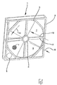
- An air dehumidifier shown in Figure 1 in perspective view 1 has one in the illustrated Embodiment approximately square frame 2.
- a sorption rotor 3 arranged rotatably about a hub 4.
- a motor As drive for the rotational movement of the sorption rotor 3 is a motor. 5
- a face or flow cross-sectional area of the sorbent rotor 3 is divided into an onflow sector 6 and an outflow sector 7.
- the Anströmsektor 6 formed below a horizontal beam 8, the two opposite sides of the frame. 2 connects with each other.
- the discharge sector 7 is above this Horizontal support 8 is formed.
- the onflow sector 6 of the air dehumidifier 1 is flows through a process / supply air flow 9, while the outflow sector 7 of the air dehumidifier 1 by a Regeneration air flow 10 is flowed through.
- the sorption rotor 3 consists of a material matrix 12 Cellulose paper whose basic structure shown in Figure 2 is that the section A of the illustrated in Figure 1 Sorption rotor 3 shows, from the - in contrast to the representation in Figure 1 - the detailed construction of the sorption rotor 3 emerges.
- the material matrix 12 consists of smooth cylindrical and kinked, corrugated or folded Cellulose paper films 13 and 14, respectively, wherein one kinked, corrugated cellulose paper sheet 13 with two flat or smooth cylindrical cellulose paper sheets 14 flow channels Forms 15, the sorption rotor 3 and its Pass material matrix 12 in the flow direction.
- the surfaces of the cellulose paper sheets 13, 14 have a capillary structure, which makes the humidity better is transferable. Furthermore, these are the flow channels 15 forming surfaces of the cellulose paper sheets 13, 14 treated with a lithium chloride solution, for example Contains 3 to 13 wt .-% lithium chloride in ethanol. As lithium chloride is used inhibited lithium chloride, whose Inhibiting agent based on chromated substances or for the purpose of inhibiting a small Proportion has lithium nitrate.
- the cellulose matrix material matrix 12 Before treatment with the lithium chloride solution, the cellulose matrix material matrix 12 is modified by means of ceramic materials. It is impregnated or infiltrated with a sol-gel system which may contain SiO 2 and / or Al 2 O 3 and / or TiO 2 and / or mullite. The infiltration of the material matrix 12 made of cellulose paper with the sol-gel system takes place at room temperature. After infiltration, the material matrix impregnated with the sol-gel system is dried at a temperature of between 100.degree. C. and 200.degree.
- this can be used to infiltrate the material matrix the sorption rotor provided sol-gel system or the gel-forming, low-viscosity liquid adsorptive solids in the form of zeolites; to achieve the germicidal effect, it is possible instead or in addition to the use of lithium chloride, a sol-gel system or to use a gel-forming, low-viscosity liquid, the in addition to the components already mentioned biocidal contains active, firmly entrenchable solids in which it e.g. to trade Amina T100 and / or Limago T100, where the latter designations are registered Brands of the CREAVIS Society for Technology and Innovation mbH acts.
- the pH and temperature of the infiltration and the Drying process are selected or adjusted so that the surfaces of the cellulose matrix material matrix 12 a defined pore structure is created, the allows a high water vapor adsorption.
- the material matrix 12 becomes a self-supporting Composite ceramic sintered. Through this sintering can an increase in temperature and moisture resistance the structure of the material matrix 12 of the sorption rotor 3 can be achieved.
- the sintering process is at temperatures above 800 degrees C, e.g. at a temperature of 850 degrees C, in air.
- the Sintering process in two stages, with the second stage the sintering process, the material matrix at temperatures above sintered at 800 degrees C of inert gas, wherein in the material matrix 12 containing carbon content with Silicon are converted to a SiC ceramic.
- the material matrix 12 of the sorbent rotor 3 in a All-ceramic implemented, whereby through this implementation finest Pores in the surfaces of the material structure 12 produced become. For common applications, the generated so finest pores for sufficient water vapor adsorption out.
Landscapes
- Chemical & Material Sciences (AREA)
- Engineering & Computer Science (AREA)
- Analytical Chemistry (AREA)
- General Chemical & Material Sciences (AREA)
- Oil, Petroleum & Natural Gas (AREA)
- Chemical Kinetics & Catalysis (AREA)
- Combustion & Propulsion (AREA)
- Mechanical Engineering (AREA)
- General Engineering & Computer Science (AREA)
- Solid-Sorbent Or Filter-Aiding Compositions (AREA)
- Drying Of Gases (AREA)
- Treatment Of Liquids With Adsorbents In General (AREA)
Description
- Figur 1
- eine Ansicht eines erfindungsgemäßen Sorptionsrotors; und
- Figur 2
- den Ausschnitt A aus Figur 1.
Claims (23)
- Sorptionsrotor (3), der drehbar gelagert ist, dessen Stirnfläche (6, 7) einen Anström- (6) und einen Abströmsektor (7) aufweist, die der Sorptionsrotor (3) bei einer Drehung durchläuft, und der eine Werkstoffmatrix (12) aufweist, die eine Wabenstruktur mit den Sorptionsrotor (3) axial durchsetzenden Strömungskanälen (15) ausbildet, dadurch gekennzeichnet, dass die Werkstoffmatrix (12) des Sorptionsrotors (3) aus Zellulosepapier ausgebildet und mittels keramischer Materialien aus einem Sol-Gel-System bzw. einer gelbildenden, niedrigviskosen Flüssigkeit infiltriert ist.
- Sorptionsrotor nach Anspruch 1, dessen aus Zellulosepapier bestehende Werkstoffmatrix mit einem SiO2 enthaltenden Sol-Gel-System infiltriert ist.
- Sorptionsrotor nach Anspruch 1 oder 2, dessen aus Zellulosepapier bestehende Werkstoffmatrix (12) mit einem Al2O3 enthaltenden Sol-Gel-System infiltriert ist.
- Sorptionsrotor nach einem der Ansprüche 1 bis 3, dessen aus Zellulosepapier bestehende Werkstoffmatrix (12) mit einem TiO2 enthaltenden Sol-Gel-System infiltriert ist.
- Sorptionsrotor nach einem der Ansprüche 1 bis 4, dessen aus Zellulosepapier ausgebildete Werkstoffmatrix (12) mit einer gelbildenden, niedrigviskosen Flüssigkeit bzw. einem Sol-Gel-System infiltriert ist, der bzw. dem adsorptiv wirkende Feststoffe beigegeben sind.
- Sorptionsrotor nach Anspruch 5, bei dem als adsorptiv wirkende Feststoffe Zeolithe vorgesehen sind.
- Sorptionsrotor nach einem der Ansprüche 1 bis 6, dessen mit dem Sol-Gel-System infiltrierte Werkstoffmatrix (12) getrocknet ist.
- Sorptionsrotor nach einem der Ansprüche 1 bis 6, dessen mit dem Sol-Gel-System infiltrierte Werkstoffmatrix (12) zu einer selbsttragenden Verbundkeramik gesintert ist.
- Sorptionsrotor nach Anspruch 8, in dessen zu einer selbsttragenden Verbundkeramik gesinterten Werkstoffmatrix (12) die Kohlenstoffanteile mit Silizium zu einer SiC-Keramik umgesetzt sind.
- Sorptionsrotor nach Anspruch 8 oder 9, dessen zu einer selbsttragenden Verbundkeramik gesinterte Werkstoffmatrix (12), in der ggf. die Kohlenstoffanteile mit Silizium zu einer SiC-Keramik umgesetzt sind, mit einem Sol-Gel-System nachinfiltriert und nachgetrocknet ist.
- Sorptionsrotor nach einem der Ansprüche 1 bis 10, dessen Werkstoffmatrix (12) mit inhibiertem Lithiumchlorid beschichtet ist.
- Sorptionsrotor nach einem der Ansprüche 1 bis 11, dessen aus Zellulosepapier ausgebildete Werkstoffmatrix (12) mit einer gelbildenden, niedrigviskosen Flüssigkeit bzw. einem Sol-Gel-System infiltriert ist, der bzw. dem biozid wirkende, fest einbindbare Feststoffe beigegeben sind.
- Sorptionsrotor nach Anspruch 12, bei dem als biozid wirkende, fest einbindbare Feststoffe Amina T100 und/oder Limago T100 (eingetragene Marken der CREAVIS Gesellschaft für Technologie und Innovation mbH) vorgesehen sind.
- Verfahren zur Herstellung eines Sorptionsrotors (3), dadurch gekennzeichnet, dass eine Werkstoffmatrix (12) des Sorptionsrotors (3) aus Zellulosepapier erstellt und mittels keramischer Materialien aus einem Sol-Gel-System bzw. einer gelbildenden, niedrigviskosen Flüssigkeit infiltriert wird.
- Verfahren nach Anspruch 14, bei dem die aus Zellulosepapier erstellte Werkstoffmatrix (12) mit einem SiO2 und/oder Al2O3 und/oder TiO2 enthaltenden Sol-Gel-System infiltriert wird.
- Verfahren nach Anspruch 14 oder 15, bei dem die aus Zellulosepapier erstellte Werkstoffmatrix (12) mit einer gelbildenden, niedrigviskosen Flüssigkeit bzw. einem Sol-Gel-System infiltriert wird, der bzw. dem adsorptiv wirkende Feststoffe, insbesondere Zeolithe, beigegeben werden.
- Verfahren nach einem der Ansprüche 14 bis 16, bei dem die aus Zellulosepapier erstellte Werkstoffmatrix (12) bei Raumtemperatur mit dem Sol-Gel-System infiltriert und bei einer Temperatur zwischen 100 Grad C und 200 Grad C getrocknet wird.
- Verfahren nach einem der Ansprüche 14 bis 17, bei dem der pH-Wert und die Temperatur bei der Infiltration und der Trocknungsverlauf so gewählt bzw. eingestellt werden, dass eine eine hohe Wasserdampfadsorption ermöglichende definierte Porenstruktur an der Werkstoffmatrix (12) erzeugt werden.
- Verfahren nach einem der Ansprüche 14 bis 16, bei dem die mit dem Sol-Gel-System infiltrierte Werkstoffmatrix (12) zu einer selbsttragenden Verbundkeramik gesintert wird.
- Verfahren nach Anspruch 19, bei dem die mit dem Sol-Gel-System infiltrierte Werkstoffmatrix (12) bei Temperaturen oberhalb von 800 Grad C, z.B. bei 850 Grad C, an Luft gesintert wird.
- Verfahren nach Anspruch 19 oder 20, bei dem die gesinterte Werkstoffmatrix (12) bei Temperaturen oberhalb von 800 Grad C an Inertgas gesintert wird, so dass in der Werkstoffmatrix (12) enthaltene Kohlenstoffanteile mit Silizium zu einer SiC-Keramik umgesetzt werden.
- Verfahren nach einem der Ansprüche 19 bis 21, bei dem die gesinterte Werkstoffmatrix (12) mit einem Sol-Gel-System nachinfiltriert und nachgetrocknet wird.
- Verfahren nach einem der Ansprüche 14 bis 22, bei dem die aus Zellulosepapier erstellte Werkstoffmatrix (12) mit einer gelbildenden, niedrigviskosen Flüssigkeit bzw. einem Sol-Gel-System infiltriert wird, der bzw. dem biozid wirkende, fest einbindbare Feststoffe, insbesondere Amina T100 und/oder Limago T100 (eingetragene Marken der CREAVIS Gesellschaft für Technologie und Innovation mbH) beigegeben werden.
Applications Claiming Priority (3)
| Application Number | Priority Date | Filing Date | Title |
|---|---|---|---|
| DE10157550A DE10157550C2 (de) | 2001-11-23 | 2001-11-23 | Sorptionsrotor |
| DE10157550 | 2001-11-23 | ||
| PCT/EP2002/013050 WO2003043719A1 (de) | 2001-11-23 | 2002-11-21 | Sorptionsrotor |
Publications (2)
| Publication Number | Publication Date |
|---|---|
| EP1446216A1 EP1446216A1 (de) | 2004-08-18 |
| EP1446216B1 true EP1446216B1 (de) | 2005-03-02 |
Family
ID=7706747
Family Applications (1)
| Application Number | Title | Priority Date | Filing Date |
|---|---|---|---|
| EP02787753A Expired - Lifetime EP1446216B1 (de) | 2001-11-23 | 2002-11-21 | Sorptionsrotor |
Country Status (6)
| Country | Link |
|---|---|
| US (1) | US7204869B2 (de) |
| EP (1) | EP1446216B1 (de) |
| AT (1) | ATE289856T1 (de) |
| AU (1) | AU2002352081A1 (de) |
| DE (2) | DE10157550C2 (de) |
| WO (1) | WO2003043719A1 (de) |
Cited By (1)
| Publication number | Priority date | Publication date | Assignee | Title |
|---|---|---|---|---|
| DE102004049418A1 (de) * | 2004-10-08 | 2006-04-13 | R. Scheuchl Gmbh | Herstellung von Massenspeicherwickel für Rotationswärmeaustauscher |
Families Citing this family (6)
| Publication number | Priority date | Publication date | Assignee | Title |
|---|---|---|---|---|
| TW200801405A (en) * | 2006-06-23 | 2008-01-01 | Ind Tech Res Inst | Dehumidifying wheel replacing device of rotary dehumidifier |
| FI123183B (fi) * | 2006-11-03 | 2012-12-14 | Flaekt Woods Ab | Laite virtauksen ohjaamiseksi |
| US7824766B2 (en) * | 2007-11-20 | 2010-11-02 | Energy Wall, Llc | Sorption paper and method of producing sorption paper |
| JP5826627B2 (ja) * | 2011-12-27 | 2015-12-02 | 株式会社西部技研 | 吸着ロータ |
| EP3258184A1 (de) | 2016-06-14 | 2017-12-20 | Emil Grüniger | Vorrichtung für ein gebäude, insbesondere eine schwimmhalle, zum austauschen von feuchtigkeit und wärme |
| EP3450862A1 (de) | 2017-08-29 | 2019-03-06 | Emil Grüniger | Vorrichtung für ein gebäude, insbesondere eine schwimmhalle, zum austauschen von feuchtigkeit und wärme |
Family Cites Families (13)
| Publication number | Priority date | Publication date | Assignee | Title |
|---|---|---|---|---|
| US3419937A (en) * | 1965-08-13 | 1969-01-07 | Corning Glass Works | Filter and method and apparatus for its production |
| US4134743A (en) * | 1970-03-31 | 1979-01-16 | Gas Developments Corporation | Desiccant apparatus and method |
| JPS5036248B1 (de) * | 1971-01-13 | 1975-11-22 | ||
| US4012206A (en) * | 1972-12-02 | 1977-03-15 | Gas Developments Corporation | Air cleaning adsorption process |
| US4093435A (en) * | 1973-11-23 | 1978-06-06 | Wing Industries Inc. | Total heat energy exchangers |
| DE2614601A1 (de) * | 1976-04-05 | 1977-10-13 | Ltg Lufttechnische Gmbh | Regenerativer waermetauscher |
| JPS5546338A (en) * | 1978-09-28 | 1980-04-01 | Ngk Insulators Ltd | Heat and shock resistant, revolving and heat-regenerating type ceramic heat exchanger body and its manufacturing |
| US4256172A (en) * | 1979-06-14 | 1981-03-17 | Ford Motor Company | Heat exchanger matrix configuration with high thermal shock resistance |
| DE69117471T2 (de) * | 1990-12-25 | 1996-09-12 | Toshimi Kuma | Gasadsorptionselement, dessen Herstellungsmethode und Verwendung |
| DE69224082T2 (de) * | 1991-10-31 | 1998-04-23 | Hitachi Shipbuilding Eng Co | Adsorptionsmittel zur Entfernung von Niedrig-Konzentrationsstickstoffoxiden |
| JP3233169B2 (ja) * | 1992-05-03 | 2001-11-26 | 株式会社西部技研 | 全熱交換器用素子およびその製造法 |
| JP2557307B2 (ja) * | 1992-10-22 | 1996-11-27 | 日立造船株式会社 | NOx吸着除去法 |
| US5685897A (en) * | 1995-07-06 | 1997-11-11 | Laroche Industries, Inc. | High strength, low pressure drop adsorbent wheel |
-
2001
- 2001-11-23 DE DE10157550A patent/DE10157550C2/de not_active Expired - Fee Related
-
2002
- 2002-11-21 WO PCT/EP2002/013050 patent/WO2003043719A1/de not_active Ceased
- 2002-11-21 AT AT02787753T patent/ATE289856T1/de active
- 2002-11-21 EP EP02787753A patent/EP1446216B1/de not_active Expired - Lifetime
- 2002-11-21 DE DE50202403T patent/DE50202403D1/de not_active Expired - Lifetime
- 2002-11-21 US US10/496,634 patent/US7204869B2/en not_active Expired - Fee Related
- 2002-11-21 AU AU2002352081A patent/AU2002352081A1/en not_active Abandoned
Cited By (2)
| Publication number | Priority date | Publication date | Assignee | Title |
|---|---|---|---|---|
| DE102004049418A1 (de) * | 2004-10-08 | 2006-04-13 | R. Scheuchl Gmbh | Herstellung von Massenspeicherwickel für Rotationswärmeaustauscher |
| DE102004049418B4 (de) * | 2004-10-08 | 2007-09-27 | R. Scheuchl Gmbh | Verfahren zur Herstellung eines Speichermassenwickels für einen Rotationswärmeaustauscher |
Also Published As
| Publication number | Publication date |
|---|---|
| ATE289856T1 (de) | 2005-03-15 |
| DE10157550C2 (de) | 2003-09-18 |
| US7204869B2 (en) | 2007-04-17 |
| EP1446216A1 (de) | 2004-08-18 |
| WO2003043719A1 (de) | 2003-05-30 |
| DE50202403D1 (en) | 2005-04-07 |
| US20050173998A1 (en) | 2005-08-11 |
| DE10157550A1 (de) | 2003-06-12 |
| AU2002352081A1 (en) | 2003-06-10 |
Similar Documents
| Publication | Publication Date | Title |
|---|---|---|
| DE69421799T2 (de) | Mit einem trockenmittel überzogenes substrat und methode zur dessen herstellung | |
| DE69418671T2 (de) | Verfahren zur Herstellung von Körpern mit imprägnierten Poren | |
| DE69012880T2 (de) | Sorptionsfiltervorrichtung. | |
| EP2809425B1 (de) | Adsorptives filtermedium | |
| DE69306909T2 (de) | Verfahren zur Adsorption und Entfernung von Stickoxiden | |
| DE102005003543A1 (de) | Feuchtigkeits- und/oder Wärmeaustauschvorrichtung, z.B. Plattenwärmetauscher, Sorptionsrotor, Adsorptionsentfeuchtungsrotor oder dgl. | |
| DE10157550C2 (de) | Sorptionsrotor | |
| DE2631092C2 (de) | Keramischer Wechselschicht-Wärmetauscher in Modulbauweise | |
| EP1283820B1 (de) | Keramisches material mit hoher porösität in gekörnter form | |
| DD158660A5 (de) | Querstromluefter | |
| DE60121264T2 (de) | Verfahren zur Herstellung eines Zeolith tragenden Adsorptionselements | |
| DE69615316T2 (de) | Keramischer Wabenkörper und Verfahren zu dessen Herstellung | |
| DE60206943T2 (de) | Enthalpietauscher | |
| DE69117471T2 (de) | Gasadsorptionselement, dessen Herstellungsmethode und Verwendung | |
| DE4129700C2 (de) | Verfahren zur Herstellung eines Wärmetauscherelements, sowie danach hergestelltes Wärmetauscherelement | |
| DE4215481A1 (de) | Geformter keramischer Katalysator und Verfahren zu seiner Herstellung | |
| DE102015224370B4 (de) | Katalysator sowie Verfahren zur Herstellung eines Katalysators | |
| EP2108440B1 (de) | Schwefelresistentes Abgasnachbehandlungssystem zur Vermeidung von Stickoxiden | |
| EP3826753B1 (de) | Filterelement für einen partikelfilter sowie abgaspartikelfilter | |
| WO2001080976A1 (de) | Mehrstufige filteranlage für gasförmige, feuchte medien | |
| CH680788A5 (en) | Filter or catalyst carrier - has structured flow channels and hollow zones for even exhaust gas flow without loss of pressure | |
| EP1634646A1 (de) | Herstellungsverfahren für ein Abgasreinigungsmittel und Abgasreinigungsmittel | |
| US5185307A (en) | Method for producing a cellular body | |
| DE4317882C2 (de) | Rotorwärmetauscher | |
| DE2429550C3 (de) | Vorrichtung zur Reinigung von Abgasen, insbesondere von Motorabgasen |
Legal Events
| Date | Code | Title | Description |
|---|---|---|---|
| PUAI | Public reference made under article 153(3) epc to a published international application that has entered the european phase |
Free format text: ORIGINAL CODE: 0009012 |
|
| 17P | Request for examination filed |
Effective date: 20040426 |
|
| AK | Designated contracting states |
Kind code of ref document: A1 Designated state(s): AT BE BG CH CY CZ DE DK EE ES FI FR GB GR IE IT LI LU MC NL PT SE SK TR |
|
| AX | Request for extension of the european patent |
Extension state: AL LT LV MK RO SI |
|
| GRAP | Despatch of communication of intention to grant a patent |
Free format text: ORIGINAL CODE: EPIDOSNIGR1 |
|
| RIN1 | Information on inventor provided before grant (corrected) |
Inventor name: WESTERDORF, THOMAS Inventor name: KLINGENBURG, HANS Inventor name: GREIL, PETER Inventor name: SIEBER, HEINO Inventor name: CAO, JING |
|
| GRAS | Grant fee paid |
Free format text: ORIGINAL CODE: EPIDOSNIGR3 |
|
| GRAA | (expected) grant |
Free format text: ORIGINAL CODE: 0009210 |
|
| AK | Designated contracting states |
Kind code of ref document: B1 Designated state(s): AT BE BG CH CY CZ DE DK EE ES FI FR GB GR IE IT LI LU MC NL PT SE SK TR |
|
| AX | Request for extension of the european patent |
Extension state: AL LT LV MK RO SI |
|
| PG25 | Lapsed in a contracting state [announced via postgrant information from national office to epo] |
Ref country code: IT Free format text: LAPSE BECAUSE OF FAILURE TO SUBMIT A TRANSLATION OF THE DESCRIPTION OR TO PAY THE FEE WITHIN THE PRESCRIBED TIME-LIMIT;WARNING: LAPSES OF ITALIAN PATENTS WITH EFFECTIVE DATE BEFORE 2007 MAY HAVE OCCURRED AT ANY TIME BEFORE 2007. THE CORRECT EFFECTIVE DATE MAY BE DIFFERENT FROM THE ONE RECORDED. Effective date: 20050302 Ref country code: IE Free format text: LAPSE BECAUSE OF FAILURE TO SUBMIT A TRANSLATION OF THE DESCRIPTION OR TO PAY THE FEE WITHIN THE PRESCRIBED TIME-LIMIT Effective date: 20050302 Ref country code: FI Free format text: LAPSE BECAUSE OF FAILURE TO SUBMIT A TRANSLATION OF THE DESCRIPTION OR TO PAY THE FEE WITHIN THE PRESCRIBED TIME-LIMIT Effective date: 20050302 Ref country code: SK Free format text: LAPSE BECAUSE OF FAILURE TO SUBMIT A TRANSLATION OF THE DESCRIPTION OR TO PAY THE FEE WITHIN THE PRESCRIBED TIME-LIMIT Effective date: 20050302 Ref country code: CZ Free format text: LAPSE BECAUSE OF FAILURE TO SUBMIT A TRANSLATION OF THE DESCRIPTION OR TO PAY THE FEE WITHIN THE PRESCRIBED TIME-LIMIT Effective date: 20050302 Ref country code: EE Free format text: LAPSE BECAUSE OF FAILURE TO SUBMIT A TRANSLATION OF THE DESCRIPTION OR TO PAY THE FEE WITHIN THE PRESCRIBED TIME-LIMIT Effective date: 20050302 |
|
| REG | Reference to a national code |
Ref country code: GB Ref legal event code: FG4D Free format text: NOT ENGLISH |
|
| REG | Reference to a national code |
Ref country code: CH Ref legal event code: EP |
|
| REG | Reference to a national code |
Ref country code: IE Ref legal event code: FG4D Free format text: GERMAN |
|
| REF | Corresponds to: |
Ref document number: 50202403 Country of ref document: DE Date of ref document: 20050407 Kind code of ref document: P |
|
| REG | Reference to a national code |
Ref country code: CH Ref legal event code: NV Representative=s name: E. BLUM & CO. PATENTANWAELTE |
|
| PG25 | Lapsed in a contracting state [announced via postgrant information from national office to epo] |
Ref country code: GR Free format text: LAPSE BECAUSE OF FAILURE TO SUBMIT A TRANSLATION OF THE DESCRIPTION OR TO PAY THE FEE WITHIN THE PRESCRIBED TIME-LIMIT Effective date: 20050602 Ref country code: BG Free format text: LAPSE BECAUSE OF FAILURE TO SUBMIT A TRANSLATION OF THE DESCRIPTION OR TO PAY THE FEE WITHIN THE PRESCRIBED TIME-LIMIT Effective date: 20050602 Ref country code: DK Free format text: LAPSE BECAUSE OF FAILURE TO SUBMIT A TRANSLATION OF THE DESCRIPTION OR TO PAY THE FEE WITHIN THE PRESCRIBED TIME-LIMIT Effective date: 20050602 |
|
| REG | Reference to a national code |
Ref country code: SE Ref legal event code: TRGR |
|
| PG25 | Lapsed in a contracting state [announced via postgrant information from national office to epo] |
Ref country code: ES Free format text: LAPSE BECAUSE OF FAILURE TO SUBMIT A TRANSLATION OF THE DESCRIPTION OR TO PAY THE FEE WITHIN THE PRESCRIBED TIME-LIMIT Effective date: 20050613 |
|
| GBT | Gb: translation of ep patent filed (gb section 77(6)(a)/1977) |
Effective date: 20050616 |
|
| PG25 | Lapsed in a contracting state [announced via postgrant information from national office to epo] |
Ref country code: PT Free format text: LAPSE BECAUSE OF FAILURE TO SUBMIT A TRANSLATION OF THE DESCRIPTION OR TO PAY THE FEE WITHIN THE PRESCRIBED TIME-LIMIT Effective date: 20050907 |
|
| REG | Reference to a national code |
Ref country code: IE Ref legal event code: FD4D |
|
| PG25 | Lapsed in a contracting state [announced via postgrant information from national office to epo] |
Ref country code: CY Free format text: LAPSE BECAUSE OF FAILURE TO SUBMIT A TRANSLATION OF THE DESCRIPTION OR TO PAY THE FEE WITHIN THE PRESCRIBED TIME-LIMIT Effective date: 20051121 |
|
| PG25 | Lapsed in a contracting state [announced via postgrant information from national office to epo] |
Ref country code: BE Free format text: LAPSE BECAUSE OF NON-PAYMENT OF DUE FEES Effective date: 20051130 Ref country code: MC Free format text: LAPSE BECAUSE OF NON-PAYMENT OF DUE FEES Effective date: 20051130 Ref country code: LU Free format text: LAPSE BECAUSE OF NON-PAYMENT OF DUE FEES Effective date: 20051130 |
|
| PLBE | No opposition filed within time limit |
Free format text: ORIGINAL CODE: 0009261 |
|
| STAA | Information on the status of an ep patent application or granted ep patent |
Free format text: STATUS: NO OPPOSITION FILED WITHIN TIME LIMIT |
|
| 26N | No opposition filed |
Effective date: 20051205 |
|
| ET | Fr: translation filed | ||
| REG | Reference to a national code |
Ref country code: CH Ref legal event code: PFA Owner name: KLINGENBURG GMBH Free format text: KLINGENBURG GMBH#BOYSTRASSE 115#45968 GLADBECK (DE) -TRANSFER TO- KLINGENBURG GMBH#BOYSTRASSE 115#45968 GLADBECK (DE) |
|
| BERE | Be: lapsed |
Owner name: KLINGENBURG G.M.B.H. Effective date: 20051130 |
|
| PGFP | Annual fee paid to national office [announced via postgrant information from national office to epo] |
Ref country code: AT Payment date: 20101119 Year of fee payment: 9 |
|
| PGFP | Annual fee paid to national office [announced via postgrant information from national office to epo] |
Ref country code: GB Payment date: 20101123 Year of fee payment: 9 Ref country code: TR Payment date: 20101111 Year of fee payment: 9 |
|
| PGFP | Annual fee paid to national office [announced via postgrant information from national office to epo] |
Ref country code: CH Payment date: 20111124 Year of fee payment: 10 Ref country code: FR Payment date: 20111125 Year of fee payment: 10 Ref country code: SE Payment date: 20111122 Year of fee payment: 10 Ref country code: NL Payment date: 20111123 Year of fee payment: 10 |
|
| PGFP | Annual fee paid to national office [announced via postgrant information from national office to epo] |
Ref country code: DE Payment date: 20120120 Year of fee payment: 10 |
|
| REG | Reference to a national code |
Ref country code: NL Ref legal event code: V1 Effective date: 20130601 |
|
| REG | Reference to a national code |
Ref country code: CH Ref legal event code: PL |
|
| REG | Reference to a national code |
Ref country code: AT Ref legal event code: MM01 Ref document number: 289856 Country of ref document: AT Kind code of ref document: T Effective date: 20121121 |
|
| GBPC | Gb: european patent ceased through non-payment of renewal fee |
Effective date: 20121121 |
|
| PG25 | Lapsed in a contracting state [announced via postgrant information from national office to epo] |
Ref country code: LI Free format text: LAPSE BECAUSE OF NON-PAYMENT OF DUE FEES Effective date: 20121130 Ref country code: AT Free format text: LAPSE BECAUSE OF NON-PAYMENT OF DUE FEES Effective date: 20121121 Ref country code: SE Free format text: LAPSE BECAUSE OF NON-PAYMENT OF DUE FEES Effective date: 20121122 Ref country code: CH Free format text: LAPSE BECAUSE OF NON-PAYMENT OF DUE FEES Effective date: 20121130 |
|
| REG | Reference to a national code |
Ref country code: FR Ref legal event code: ST Effective date: 20130731 |
|
| PG25 | Lapsed in a contracting state [announced via postgrant information from national office to epo] |
Ref country code: NL Free format text: LAPSE BECAUSE OF NON-PAYMENT OF DUE FEES Effective date: 20130601 |
|
| REG | Reference to a national code |
Ref country code: DE Ref legal event code: R119 Ref document number: 50202403 Country of ref document: DE Effective date: 20130601 |
|
| PG25 | Lapsed in a contracting state [announced via postgrant information from national office to epo] |
Ref country code: DE Free format text: LAPSE BECAUSE OF NON-PAYMENT OF DUE FEES Effective date: 20130601 |
|
| PG25 | Lapsed in a contracting state [announced via postgrant information from national office to epo] |
Ref country code: GB Free format text: LAPSE BECAUSE OF NON-PAYMENT OF DUE FEES Effective date: 20121121 Ref country code: FR Free format text: LAPSE BECAUSE OF NON-PAYMENT OF DUE FEES Effective date: 20121130 |
|
| PG25 | Lapsed in a contracting state [announced via postgrant information from national office to epo] |
Ref country code: TR Free format text: LAPSE BECAUSE OF NON-PAYMENT OF DUE FEES Effective date: 20121121 |