EP1445783A2 - Switch gear - Google Patents
Switch gear Download PDFInfo
- Publication number
- EP1445783A2 EP1445783A2 EP04001944A EP04001944A EP1445783A2 EP 1445783 A2 EP1445783 A2 EP 1445783A2 EP 04001944 A EP04001944 A EP 04001944A EP 04001944 A EP04001944 A EP 04001944A EP 1445783 A2 EP1445783 A2 EP 1445783A2
- Authority
- EP
- European Patent Office
- Prior art keywords
- ring
- contact
- casing
- wall
- shaped
- Prior art date
- Legal status (The legal status is an assumption and is not a legal conclusion. Google has not performed a legal analysis and makes no representation as to the accuracy of the status listed.)
- Granted
Links
Images



Classifications
-
- H—ELECTRICITY
- H01—ELECTRIC ELEMENTS
- H01H—ELECTRIC SWITCHES; RELAYS; SELECTORS; EMERGENCY PROTECTIVE DEVICES
- H01H9/00—Details of switching devices, not covered by groups H01H1/00 - H01H7/00
- H01H9/02—Bases, casings, or covers
- H01H9/04—Dustproof, splashproof, drip-proof, waterproof, or flameproof casings
-
- H—ELECTRICITY
- H05—ELECTRIC TECHNIQUES NOT OTHERWISE PROVIDED FOR
- H05B—ELECTRIC HEATING; ELECTRIC LIGHT SOURCES NOT OTHERWISE PROVIDED FOR; CIRCUIT ARRANGEMENTS FOR ELECTRIC LIGHT SOURCES, IN GENERAL
- H05B3/00—Ohmic-resistance heating
- H05B3/20—Heating elements having extended surface area substantially in a two-dimensional [2D] plane, e.g. plate-heater
-
- H—ELECTRICITY
- H05—ELECTRIC TECHNIQUES NOT OTHERWISE PROVIDED FOR
- H05B—ELECTRIC HEATING; ELECTRIC LIGHT SOURCES NOT OTHERWISE PROVIDED FOR; CIRCUIT ARRANGEMENTS FOR ELECTRIC LIGHT SOURCES, IN GENERAL
- H05B3/00—Ohmic-resistance heating
- H05B3/02—Details
- H05B3/03—Electrodes
-
- H—ELECTRICITY
- H01—ELECTRIC ELEMENTS
- H01H—ELECTRIC SWITCHES; RELAYS; SELECTORS; EMERGENCY PROTECTIVE DEVICES
- H01H11/00—Apparatus or processes specially adapted for the manufacture of electric switches
- H01H11/04—Apparatus or processes specially adapted for the manufacture of electric switches of switch contacts
- H01H11/06—Fixing of contacts to carrier ; Fixing of contacts to insulating carrier
- H01H2011/062—Fixing of contacts to carrier ; Fixing of contacts to insulating carrier by inserting only
-
- H—ELECTRICITY
- H01—ELECTRIC ELEMENTS
- H01H—ELECTRIC SWITCHES; RELAYS; SELECTORS; EMERGENCY PROTECTIVE DEVICES
- H01H21/00—Switches operated by an operating part in the form of a pivotable member acted upon directly by a solid body, e.g. by a hand
- H01H21/02—Details
- H01H21/18—Movable parts; Contacts mounted thereon
- H01H21/22—Operating parts, e.g. handle
- H01H21/24—Operating parts, e.g. handle biased to return to normal position upon removal of operating force
Definitions
- the present invention relates to a switch gear, and more specifically, it relates to a shield structure of a switch gear used for refrigerators and so on.
- Known shield structures of switch gears include a shield structure in which, for example, when a casing and a cover are fitted together, the joint of the casing and the cover are heated or welded with supersonic waves after they are overlapped with each other.
- a shield structure in which a resin adhesive is poured between the engagement surfaces of the casing and the cover to bond them after they are overlapped with each other (refer to, e.g. Japanese Unexamined Patent Application Publication No. 07-006660 and Japanese Unexamined Patent Application Publication No. 13-077503)
- the known shield structures of switch gears have the problem of increasing shielding process steps to increase cost because the welding or bonding is performed after the assembly of the switch gear in both of the case of welding the joint surface and the case of pouring an adhesion into the space between the engagement surfaces to bond them. They also have the problem of difficulty in maintenance since they need facilities specific for shielding.
- the object of the present invention is to solve the above-described problems to provide a switch-gear shield structure capable of achieving low cost without special post-processes, such as welding and bonding, with high sealing performance and a simple structure in which two components are fitted together.
- a first means of the present invention is characterized by including a casing having a storage section opened on one side; a contact section having a fixed contact and a moving contact disposed in the storage section; a drive member for driving the contact section to bring it into or out of contact with each other; a lever connected to the drive member to be rotated in the casing; and a cover mounted to cover the opening of the storage section of the casing, wherein the joint of the casing and the cover has a ring-shaped projected wall on one side and a ring-shaped recessed groove to be fitted on the projected wall on the other side; wherein the ring-shaped projected wall has an elastically transformable part at the end and has an inclined part forming a slope in the vicinity of the bottom of the ring-shaped recessed groove; and wherein when the casing and the caver are fitted together, the elastically transformable part and the inclined part are brought into close contact with each other by pressure contact.
- a second means is characterized in that the elastically transformable part includes an elastically transformable thin wall.
- a third means is characterized in that the elastically transformable thin wall is formed in crotch shape having a notch in the center.
- a fourth means is characterized in that at least one of opposing side walls with the ring-shaped recessed groove therebetween is shaped in the form of a projected wall; wherein an elastically transformable part is formed at the end of the projected side wall; and wherein an inclined part having a slope extending outward is formed in the vicinity of the base of the ring-shaped projected wall opposite to the elastically transformable part.
- a fifth means is characterized in that the end of the projected side wall is tapered off so as to be elastically transformed.
- the switch gear of the invention includes: a casing having a storage section opened on one side; a contact section having a fixed contact and a moving contact disposed in the storage section; a drive member for driving the contact section to bring it into or out of contact with each other; a lever connected to the drive member to be rotated in the casing; and a cover mounted to cover the opening of the storage section of the casing, wherein the joint of the casing and the cover has a ring-shaped projected wall on one side and a ring-shaped recessed groove to be fitted on the projected wall on the other side; wherein the ring-shaped projected wall has an elastically transformable part at the end and has an inclined part forming a slope in the vicinity of the bottom of the ring-shaped recessed groove; and wherein when the casing and the caver are fitted together, the elastically transformable part and the inclined part are brought into close contact with each other by pressure contact.
- the elastically transformable parts formed at the end of the ring-shaped projected wall are elastically transformed by the inclined parts formed in the lower vicinity of the ring-shaped recessed groove to be pushed with elasticity. Accordingly, there is no need for special post process such as welding and bonding for shielding the switch gear, thus achieving low cost and high sealing performance with a simple structure in which two components are merely fitted together.
- the elastically transformable part includes an elastically transformable thin wall, it is easily transformed, thus ensuring elasticity with a simple structure.
- the elastically transformable thin wall is formed in crotch shape having a notch in the center, thus allowing pressure contact at two positions to ensure sealing performance with a simple structure.
- At least one of opposing side walls with the ring-shaped recessed groove therebetween is shaped in the form of a projected wall, at the end of which an elastically transformable part is formed, and an inclined part that forms an externally extending slope is formed in the vicinity of the base opposite to the elastically transformable part, they are brought into double pressure contact with each other in plural positions, thus providing hither sealing performance.
- the end of the projected side wall is tapered off to allow elastic transformation, thus ensuring elasticity with a simple structure.
- a casing 1 is made of an insulating material such as a synthetic resin in approximately rectangular shape and is formed of a flat panel 1a and a base 1b.
- the panel 1a has a window hole 1c on the top, into which a later-described lever 7 is rotatably inserted.
- an opening 1d is provided that is opened in one side of the casing 1.
- a storage section 1e is opened in box shape in one side of the base 1b, in which a later described contact section and so on are disposed.
- an elastic arm 1f having one free end is formed, at which a locking section 1g is formed which has wavy unevenness to be fitted to a panel of an electronic device or the like.
- a shaft hole 1h is also provided on the back of the casing 1 in which a rotating shaft 2b of a later-described drive member 2 is supported.
- raised engagement projections 1i are formed which are to be fitted in engagement holes 6e of a later-described cover 6.
- the storage section 1e has a support shaft 1j by which a rotating shaft 2a of the later-described drive member 2 is provided at upper one end and contact holding sections 1k, 1l, and 1m in which later-described contact section is inserted and held in the lower center, respectively.
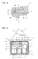
- a ring-shaped projected wall 1n is provided around the storage section 1e so as to protrude outward and surround the periphery of the storage section 1e.
- On the end of the ring-shaped projected wall 1n crotch thin walls 1p having a central notch 1o are formed.
- the thin walls 1p can be elastically transformed to serve as elastically transformable parts.
- An inclined part 1q which forms a slope extending externally and increasing in thickness toward the base is formed in the vicinity of the base of the ring-shaped projected wall 1n, with which a thin wall 6i is into contact, the thin wall 6i being an elastically transformable part provided to one of opposing side walls of the cover 6 with a ring-shaped recessed groove 6f therebetween.
- the drive member 2 is formed of an insulating material such as a synthetic resin and includes large and small cylindrical rotating shafts 2a and 2b, a lever engaging section 2c provided concentrically with the rotating shafts 2a and 2b, and a rotating arm 2d for driving the later-described contact section.
- the engagement holes 6e of the later-described cover 6 is fitted on the lever engaging section 2c and the rotating shafts 2a and 2b are rotatably supported by the support shaft 1j and the shaft hole 1h of the casing 1.
- the contact section includes a pair of fixed contacts 3 and 4 formed by stamping and bending an electrically conductive metal plate and a moving contact 5 for bringing the fixed contacts 3 and 4 into and out of contact with each other.
- contacts 3a and 4a made of precious metal with high electrical conductivity are firmly fixed, respectively, while at the other ends, externally leading contact terminals 3b and 4b are provided.
- the moving contact 5 is made of an elastic thin metal plate and includes a moving arm plate 5b having a contact 5a fixed to one end and a contact terminal 5c connected to the arm plate 5b cut into a specified shape in a doubled state.
- the moving contact 5 is formed of a metal plate thinner than those of the fixed contacts 3 and 4 since it includes the moving arm 5b, the contact terminal 5c is formed in a doubled state, thus being capable of increasing the strength of the terminal. Since the moving contact 5 is cut into a specified shape in a doubled state, the accuracy of the external dimension can be ensured in the last cutting process, thus increasing the accuracy of engagement with the counterpart, and further improving the shield performance with a terminal holding section 6d of the later-described cover 6.
- the fixed contacts 3 and 4 and the moving contact 5 are retained to each other by the contact terminals 3b, 4b, and 5c inserted into the contact holding sections 1k, 1l, and 1m of the casing 1, respectively.
- the cover 6 is made of an insulating material such as a synthetic resin in box shape opened on one side. On the front upper end of the cover 6 opposite to the opening, a locking section 6a with wavy unevenness is formed. The locking section 6a and the locking section 1g of the elastic arm 1f of the casing 1 cooperate, thereby being fitted to a panel of an electronic device and so on.
- terminal holding sections 6b, 6c, and 6d from which the contact terminals 3b, 4b, and 5c of the contact section are projected ant lead out, are provided. Also the engagement holes 6e are formed in opposite side plates of the cover 6 with the opening therebetween for coming into engagement with the engagement projections 1i of the opposing sides of the storage section 1e of the casing 1 to bring the cover 6 into engagement with the casing 1.
- the ring-shaped recessed groove 6f is provided around the periphery of the opening of the cover 6 to surround the periphery of the opening.
- a pair of inclined parts 6g and 6g that tapers off toward the lower part is provided.
- an inner side wall 6h is formed to project, end of which tapers off so as to be elastically transformed to construct the thin wall 6i.
- the tapered thin wall 6i is constructed as an elastically transformable part.
- the cover 6 When the switch gear of the invention is assembled, the cover 6 is fitted to cover the opening of the storage section 1e of the casing 1 and the ring-shaped projected wall 1n surrounding the periphery of the storage section 1e of the casing 1 is fitted in the ring-shaped recessed groove 6f of the cover 6.
- the crotch thin walls 1p and 1p serving as elastic transformable parts, provided at the end of the ring-shaped projected wall 1n, are brought into contact with the tapered inclined parts 6g and 6g provided in the vicinity of the bottom of the ring-shaped recessed groove 6f, so that the thin walls 1p and 1p are elastically transformed inwardly along the inclined parts 6g and 6g. Since the thin walls 1p and 1p are brought into pressure contact with the inclined parts 6g and 6g by an elastic force, the casing 1 and the cover 6 are brought into close engagement with each other. Thus high sealing performance can be provided with a simple structure in which two components are merely fitted together.
- the elastically transformable part has the elastically deformable thin walls 1p, it can easily be transformed and ensure elasticity with a simple structure. Furthermore, the thin walls 1p are formed in crotch shape with a central notch, thus allowing pressure contact at two positions to ensure sealing performance with a simple structure.
- the externally extending inclined part 1q that increases in thickness toward the base is formed in the vicinity of the base of the ring-shaped projected wall 1n, with which, of the opposing side walls of the cover 6 with the ring-shaped recessed groove 6f therebetween, the tapered thin wall 6i serving as the elastically transformable part of the inner side wall 6h is brought into contact.
- the thin wall 6i is elastically brought into pressure contact with the inclined part 1q, so that the casing 1 and the cover 6 can be fitted together in closer contact with each other.
- the end of the projected side wall 6h is tapered off to allow elastic transformation, thus ensuring elasticity with a simple structure.
- the lever 7 is made of an insulating material such as a synthetic resin in approximately angular form, which includes an operating section 7a turned by an actuator built in an electronic device and an engagement hole 7b to be fitted on the lever engaging section 2c of the drive member 2 for driving the contact section. Also a spring bearing 7c is formed on the bottom for locking a return spring 8 which is brought into engagement with the lever 7 to bias the lever 7 to the initial position.
- the return spring 8 and the lever 7 are inserted and held into the window hole 1c of the panel 1a of the casing 1 and the lever engaging section 2c of the drive member 2 is fitted and fixed into the engagement hole 7b of the lever 7 while the rotating shaft 2a of the drive member 2 is supported by the support shaft 1j of the storage section 1e of the base 1b.
- the contact terminals 3b, 4b, and 5c of the fixed contacts 3 and 4 and the moving contact 5 are inserted into the contact holding sections 1k, 1l, and 1m of the storage section 1e, respectively, to retain them.
- the cover 6 is then fitted thereon to cover the opening of the storage section 1e and the contact terminals 3b, 4b, and 5c are protruded from the terminal holding sections 6b, 6c, and 6d, respectively, to hold them.
- the engagement projections 1i on the sides of the casing 1 are brought into engagement with the engagement holes 6e of the side plates of the cover 6, with the ring-shaped projected wall 1n around the periphery of the storage section 1e of the casing 1 and the ring-shaped recessed groove 6f of the cover 6 in engagement with each other, so that the cover 6 is firmly fixed to the casing 1; thus the assembly is completed.
- Fig. 5 shows the initial state, in which the lever 7 is urged upward by the return spring 8 and the rotating arm 2d of the drive member 2 lifts the arm plate 5b of the moving contact 5 upward to turn the contact 3a of the fixed contact 3 and the contact 5a of the moving contact 5 to the on position.
- the casing 1 when the casing and the cover of the switch gear are joined together, the casing 1 is provided with the ring-shaped projected wall 1n and the cover 6 is provided with the ring-shaped recessed groove 6f that is to be fitted on the projected wall 1n, wherein the ring-shaped projected wall 1n has the crotch thin walls 1p serving as elastically transformable parts and the ring-shaped recessed groove 6f has the tapered inclined parts 6g in the vicinity of the bottom, and wherein when the casing 1 and the cover 6 are fitted together, the thin walls 1p and the inclined parts 6g are brought into close pressure contact with each other.
- the thin walls 1p at the end of the ring-shaped projected wall 1n are elastically transformed by the inclined parts 6g formed in the lower vicinity of the ring-shaped recessed groove 6f to be pushed with elasticity. Accordingly, there is no need for special post process such as welding and bonding for shielding the switch gear, thus achieving low cost and high sealing performance with a simple structure in which two components are merely fitted together.
Landscapes
- Rotary Switch, Piano Key Switch, And Lever Switch (AREA)
- Switch Cases, Indication, And Locking (AREA)
- Mechanisms For Operating Contacts (AREA)
- Push-Button Switches (AREA)
- General Details Of Gearings (AREA)
- Sealing Devices (AREA)
Abstract
Description
Claims (5)
- A switch gear characterized by comprising: a casing including a storage section opened on one side; a contact section including a fixed contact and a moving contact disposed in the storage section; a drive member for driving the contact section to bring it into or out of contact with each other; a lever connected to the drive member to be rotated in the casing; and a cover mounted to cover the opening of the storage section of the casing, wherein the joint of the casing and the cover has a ring-shaped projected wall on one side and a ring-shaped recessed groove to be fitted on the projected wall on the other side; wherein the ring-shaped projected wall has an elastically transformable part at the end and has an inclined part forming a slope in the vicinity of the bottom of the ring-shaped recessed groove; and wherein when the casing and the caver are fitted together, the elastically transformable part and the inclined part are brought into close contact with each other by pressure contact.
- A switch gear according to Claim 1, characterized in that the elastically transformable part includes an elastically transformable thin wall.
- A switch gear according to Claim 2, characterized in that the elastically transformable thin wall is formed in crotch shape having a notch in the center.
- A switch gear according to one of Claims 1 to 3, characterized in that at least one of opposing side walls with the ring-shaped recessed groove therebetween is shaped in the form of a projected wall; wherein an elastically transformable part is formed at the end of the projected side wall; and wherein an inclined part having a slope extending outward is formed in the vicinity of the base of the ring-shaped projected wall opposite to the elastically transformable part.
- A switch gear according to Claim 4, characterized in that the end of the projected side wall is tapered off so as to be elastically transformed.
Applications Claiming Priority (2)
| Application Number | Priority Date | Filing Date | Title |
|---|---|---|---|
| JP2003031621 | 2003-02-07 | ||
| JP2003031621A JP2004241327A (en) | 2003-02-07 | 2003-02-07 | Switch device |
Publications (3)
| Publication Number | Publication Date |
|---|---|
| EP1445783A2 true EP1445783A2 (en) | 2004-08-11 |
| EP1445783A3 EP1445783A3 (en) | 2005-09-14 |
| EP1445783B1 EP1445783B1 (en) | 2006-12-20 |
Family
ID=32653028
Family Applications (1)
| Application Number | Title | Priority Date | Filing Date |
|---|---|---|---|
| EP04001944A Expired - Lifetime EP1445783B1 (en) | 2003-02-07 | 2004-01-29 | Switch gear |
Country Status (6)
| Country | Link |
|---|---|
| EP (1) | EP1445783B1 (en) |
| JP (1) | JP2004241327A (en) |
| KR (1) | KR100546423B1 (en) |
| CN (1) | CN1246870C (en) |
| DE (1) | DE602004003727T2 (en) |
| TW (1) | TWI235397B (en) |
Cited By (1)
| Publication number | Priority date | Publication date | Assignee | Title |
|---|---|---|---|---|
| US9911558B2 (en) * | 2013-05-31 | 2018-03-06 | Te Connectivity Germany Gmbh | Switch contact chamber seal |
Families Citing this family (7)
| Publication number | Priority date | Publication date | Assignee | Title |
|---|---|---|---|---|
| JP4864422B2 (en) * | 2005-11-08 | 2012-02-01 | 株式会社東芝 | Induction heating cooker |
| JP4862697B2 (en) * | 2007-03-08 | 2012-01-25 | パナソニック株式会社 | Switch device |
| JP5497591B2 (en) * | 2010-09-09 | 2014-05-21 | アルプス電気株式会社 | Switch device |
| CN102931011A (en) * | 2011-08-09 | 2013-02-13 | 株式会社Magma | Button switch device easy to assemble cover |
| JP7010484B2 (en) * | 2018-07-17 | 2022-01-26 | 帝国通信工業株式会社 | Swingable electronic components |
| CN112825291B (en) * | 2019-11-21 | 2025-08-26 | 惠州冠泰电子有限公司 | A sealed refrigerator door switch |
| CN112951659B (en) * | 2021-01-15 | 2025-06-24 | 厦门宏发汽车电子有限公司 | A silent relay |
Family Cites Families (6)
| Publication number | Priority date | Publication date | Assignee | Title |
|---|---|---|---|---|
| DE2509207C3 (en) * | 1975-03-04 | 1979-02-15 | Brown, Boveri & Cie Ag, 6800 Mannheim | Housing for a magnetic release, especially for residual current circuit breakers |
| US4652706A (en) * | 1986-01-29 | 1987-03-24 | Tower Manufacturing Corporation | Double pole switch construction |
| US5260532A (en) * | 1991-11-01 | 1993-11-09 | United Technologies Automotive, Inc. | Sealed housing for a remote switching device |
| US5276299A (en) * | 1991-11-05 | 1994-01-04 | Otis Elevator Company | Elevator limit switch |
| DE29612829U1 (en) * | 1996-07-24 | 1996-10-02 | Georg Schlegel GmbH & Co, 88525 Dürmentingen | Protective cap for actuators of control devices |
| JP2000331567A (en) * | 1999-05-24 | 2000-11-30 | Mikku Enterprise:Kk | Waterproof type lever switch |
-
2003
- 2003-02-07 JP JP2003031621A patent/JP2004241327A/en not_active Withdrawn
-
2004
- 2004-01-12 KR KR1020040001943A patent/KR100546423B1/en not_active Expired - Fee Related
- 2004-01-29 DE DE602004003727T patent/DE602004003727T2/en not_active Expired - Fee Related
- 2004-01-29 EP EP04001944A patent/EP1445783B1/en not_active Expired - Lifetime
- 2004-02-04 CN CNB2004100040363A patent/CN1246870C/en not_active Expired - Fee Related
- 2004-02-05 TW TW093102627A patent/TWI235397B/en not_active IP Right Cessation
Cited By (1)
| Publication number | Priority date | Publication date | Assignee | Title |
|---|---|---|---|---|
| US9911558B2 (en) * | 2013-05-31 | 2018-03-06 | Te Connectivity Germany Gmbh | Switch contact chamber seal |
Also Published As
| Publication number | Publication date |
|---|---|
| EP1445783A3 (en) | 2005-09-14 |
| JP2004241327A (en) | 2004-08-26 |
| KR100546423B1 (en) | 2006-01-26 |
| DE602004003727T2 (en) | 2007-10-04 |
| CN1246870C (en) | 2006-03-22 |
| CN1521782A (en) | 2004-08-18 |
| TWI235397B (en) | 2005-07-01 |
| EP1445783B1 (en) | 2006-12-20 |
| KR20040072031A (en) | 2004-08-16 |
| DE602004003727D1 (en) | 2007-02-01 |
| TW200503034A (en) | 2005-01-16 |
Similar Documents
| Publication | Publication Date | Title |
|---|---|---|
| US20060131153A1 (en) | Push-on switch | |
| JP2000133090A (en) | Panel switch and mounting method to the device | |
| EP1445783B1 (en) | Switch gear | |
| US6559398B2 (en) | Rocker-type power-supply switch device | |
| WO2013137201A1 (en) | Switch | |
| CN101604589A (en) | Push-button switch | |
| US4055736A (en) | Push switch | |
| JP2004031171A (en) | 2-stage operation push switch | |
| JP2003288820A (en) | Tightly sealed push switch | |
| JPH11232962A (en) | Push-on switch | |
| US2429770A (en) | Electric snap-action switch | |
| EP3664115A2 (en) | A snap-action switch and method of assembling same | |
| JP2004311128A (en) | Push-button switch | |
| KR101310676B1 (en) | Switch having a complementary diode unit and method of mounting the diode unit on the switch | |
| JPH1173839A (en) | Push button switch | |
| JP4720470B2 (en) | Compound switch | |
| JP4087603B2 (en) | Slide type electrical parts | |
| JP2022043622A (en) | Push switch | |
| JP4720737B2 (en) | Leaf switch | |
| JP4326987B2 (en) | Switch device | |
| JP4524247B2 (en) | Switch device | |
| JPS6025791Y2 (en) | alternate closing switch | |
| JP2005209565A (en) | Push-button switch | |
| JP2597543Y2 (en) | Compact switch | |
| JP2001143571A (en) | Switching device |
Legal Events
| Date | Code | Title | Description |
|---|---|---|---|
| PUAI | Public reference made under article 153(3) epc to a published international application that has entered the european phase |
Free format text: ORIGINAL CODE: 0009012 |
|
| AK | Designated contracting states |
Kind code of ref document: A2 Designated state(s): AT BE BG CH CY CZ DE DK EE ES FI FR GB GR HU IE IT LI LU MC NL PT RO SE SI SK TR |
|
| AX | Request for extension of the european patent |
Extension state: AL LT LV MK |
|
| PUAL | Search report despatched |
Free format text: ORIGINAL CODE: 0009013 |
|
| AK | Designated contracting states |
Kind code of ref document: A3 Designated state(s): AT BE BG CH CY CZ DE DK EE ES FI FR GB GR HU IE IT LI LU MC NL PT RO SE SI SK TR |
|
| AX | Request for extension of the european patent |
Extension state: AL LT LV MK |
|
| RIC1 | Information provided on ipc code assigned before grant |
Ipc: 7H 01H 3/00 A Ipc: 7H 01H 21/28 B Ipc: 7H 01H 21/08 B |
|
| GRAP | Despatch of communication of intention to grant a patent |
Free format text: ORIGINAL CODE: EPIDOSNIGR1 |
|
| 17P | Request for examination filed |
Effective date: 20051025 |
|
| GRAS | Grant fee paid |
Free format text: ORIGINAL CODE: EPIDOSNIGR3 |
|
| AKX | Designation fees paid |
Designated state(s): DE FR GB IT |
|
| GRAA | (expected) grant |
Free format text: ORIGINAL CODE: 0009210 |
|
| AK | Designated contracting states |
Kind code of ref document: B1 Designated state(s): DE FR GB IT |
|
| REG | Reference to a national code |
Ref country code: GB Ref legal event code: FG4D |
|
| REF | Corresponds to: |
Ref document number: 602004003727 Country of ref document: DE Date of ref document: 20070201 Kind code of ref document: P |
|
| ET | Fr: translation filed | ||
| PLBE | No opposition filed within time limit |
Free format text: ORIGINAL CODE: 0009261 |
|
| STAA | Information on the status of an ep patent application or granted ep patent |
Free format text: STATUS: NO OPPOSITION FILED WITHIN TIME LIMIT |
|
| 26N | No opposition filed |
Effective date: 20070921 |
|
| PGFP | Annual fee paid to national office [announced via postgrant information from national office to epo] |
Ref country code: GB Payment date: 20090123 Year of fee payment: 6 |
|
| PGFP | Annual fee paid to national office [announced via postgrant information from national office to epo] |
Ref country code: DE Payment date: 20090327 Year of fee payment: 6 Ref country code: IT Payment date: 20090123 Year of fee payment: 6 |
|
| PGFP | Annual fee paid to national office [announced via postgrant information from national office to epo] |
Ref country code: FR Payment date: 20090120 Year of fee payment: 6 |
|
| GBPC | Gb: european patent ceased through non-payment of renewal fee |
Effective date: 20100129 |
|
| REG | Reference to a national code |
Ref country code: FR Ref legal event code: ST Effective date: 20100930 |
|
| PG25 | Lapsed in a contracting state [announced via postgrant information from national office to epo] |
Ref country code: FR Free format text: LAPSE BECAUSE OF NON-PAYMENT OF DUE FEES Effective date: 20100201 |
|
| PG25 | Lapsed in a contracting state [announced via postgrant information from national office to epo] |
Ref country code: DE Free format text: LAPSE BECAUSE OF NON-PAYMENT OF DUE FEES Effective date: 20100803 |
|
| PG25 | Lapsed in a contracting state [announced via postgrant information from national office to epo] |
Ref country code: GB Free format text: LAPSE BECAUSE OF NON-PAYMENT OF DUE FEES Effective date: 20100129 |
|
| PG25 | Lapsed in a contracting state [announced via postgrant information from national office to epo] |
Ref country code: IT Free format text: LAPSE BECAUSE OF NON-PAYMENT OF DUE FEES Effective date: 20100129 |