EP1445648A1 - Light quantity regulating device and optical system having it and photographing device - Google Patents
Light quantity regulating device and optical system having it and photographing device Download PDFInfo
- Publication number
- EP1445648A1 EP1445648A1 EP02802356A EP02802356A EP1445648A1 EP 1445648 A1 EP1445648 A1 EP 1445648A1 EP 02802356 A EP02802356 A EP 02802356A EP 02802356 A EP02802356 A EP 02802356A EP 1445648 A1 EP1445648 A1 EP 1445648A1
- Authority
- EP
- European Patent Office
- Prior art keywords
- phase difference
- aperture
- adjusting device
- light quantity
- wave front
- Prior art date
- Legal status (The legal status is an assumption and is not a legal conclusion. Google has not performed a legal analysis and makes no representation as to the accuracy of the status listed.)
- Withdrawn
Links
Images












Classifications
-
- G—PHYSICS
- G02—OPTICS
- G02B—OPTICAL ELEMENTS, SYSTEMS OR APPARATUS
- G02B5/00—Optical elements other than lenses
- G02B5/20—Filters
- G02B5/205—Neutral density filters
-
- G—PHYSICS
- G03—PHOTOGRAPHY; CINEMATOGRAPHY; ANALOGOUS TECHNIQUES USING WAVES OTHER THAN OPTICAL WAVES; ELECTROGRAPHY; HOLOGRAPHY
- G03B—APPARATUS OR ARRANGEMENTS FOR TAKING PHOTOGRAPHS OR FOR PROJECTING OR VIEWING THEM; APPARATUS OR ARRANGEMENTS EMPLOYING ANALOGOUS TECHNIQUES USING WAVES OTHER THAN OPTICAL WAVES; ACCESSORIES THEREFOR
- G03B9/00—Exposure-making shutters; Diaphragms
- G03B9/02—Diaphragms
-
- G—PHYSICS
- G02—OPTICS
- G02B—OPTICAL ELEMENTS, SYSTEMS OR APPARATUS
- G02B5/00—Optical elements other than lenses
- G02B5/005—Diaphragms
-
- H—ELECTRICITY
- H04—ELECTRIC COMMUNICATION TECHNIQUE
- H04N—PICTORIAL COMMUNICATION, e.g. TELEVISION
- H04N23/00—Cameras or camera modules comprising electronic image sensors; Control thereof
- H04N23/70—Circuitry for compensating brightness variation in the scene
- H04N23/75—Circuitry for compensating brightness variation in the scene by influencing optical camera components
Definitions
- the present invention relates to a light quantity adjusting device suitable for use in an image taking apparatus such as a video camera or a digital still camera, and to a technique capable of suppressing a deterioration of optical performance even in an image pickup element having a small pixel pitch.
- a light quantity adjusting device for changing an aperture diameter produced by a plurality of diaphragm blades to adjust a quantity of light is used.
- the aperture diameter becomes too small, the deterioration of optical performance due to light diffraction becomes a problem.
- a diaphragm apparatus in which an ND filter is bonded to diaphragm blades so as to be positioned within an aperture formed by the diaphragm blades and have a plurality of regions for which uniform transmittance is set, and the transmittance is set so as to gradually increase from the outside of the aperture to the inside thereof.
- a diaphragm apparatus in which mechanical diaphragm blades are moved during a control from a full open state to a state with a predetermined aperture area, and in small aperture control where the aperture is not larger than a predetermined diaphragm value, an ND filter whose transmittance is continuously changed according to the density is entered into the aperture successively from a filter portion having high transmittance.
- an object of the present invention is to suppress a deterioration of optical performance due to the influence of a minute thickness component of a filter member in a light quantity adjusting device for adjusting a quantity of light using a diaphragm in combination with the filter member for attenuating transmitted light such as an ND filter.
- a light quantity adjusting device which includes a diaphragm for forming an aperture and a filter member for attenuating a quantity of light passing through the aperture of the diaphragm and in which a cover ratio of the aperture by the filter member is changed, in a state in which the aperture is completely covered with the filter member, setting is conducted such that a phase difference between lights with a predetermined wavelength ⁇ which pass through positions of the filter member with different transmittances becomes substantially 0 ⁇ , substantially 1 ⁇ , or substantially 2 ⁇ .
- phase difference of "substantially 0 ⁇ , substantially 1 ⁇ , or substantially 2 ⁇ ” means that a phase difference including a manufacturing error is in a range of ⁇ 0 ⁇ (1/5) ⁇ , ⁇ 1 ⁇ (1/5) ⁇ , or ⁇ 2 ⁇ (1/5) ⁇ . If the phase difference is within this range, it is assumed to be a phase difference of substantially 0 ⁇ , 1 ⁇ , or 2 ⁇ , thus adequately achieving an initial object of the present invention.
- the device comprises means for setting to a predetermined value a phase difference between lights which pass through positions of the filter member with different transmittances, in a state in which the aperture is completely covered with the filter member.
- the light quantity adjusting device is suitably used for adjusting the quantity of light passing through an optical system, and suitable for use in an optical system of an image taking apparatus for forming an image on an image pickup element (photoelectric conversion element) such as a CCD or a CMOS in particular.
- an image pickup element photoelectric conversion element
- Figs. 15A, 15B, 15C, 15D and 15E show point image intensity distributions Q around a geometrical-optical imaging point I when is a filter P and an aperture diaphragm S are located in front (the object side) of a stigmatic ideal lens L and a parallel light beam which is a plane wave of monochromatic light with a wavelength ⁇ is incident.
- Fig. 15A shows a state in which a thickness of the filter P is zero and a transmission wave front is not influenced thereby.
- the intensity distribution Q becomes a diffraction pattern according to a relationship between an F number F and the wavelength ⁇ of a light beam (reference: "Wave Front Optics for Lens Design", Tohru Kusakawa, Tokai University Press).
- the diaphragm S When the diaphragm S is a circular aperture, a single point image with a radius of 1.22 F ⁇ is imaged and a diffraction light pattern of ring-shaped weak light is formed in its vicinities.
- a thickness of a region (lower side in the drawing) of the filter P corresponding to a half of the aperture produced by the diaphragm S is increased by a minute quantity and setting is conducted such that a phase difference of transmission wave front becomes (1/4) ⁇ as shown in Fig. 15B, a point image with a small intensity appears beside the point image with a strong intensity.
- the intensity distribution Q does not become a single point image but becomes an intensity distribution including two point images which are separated from each other in a vertical direction in the drawing. This is because, of lights focused into the geometrical-optical imaging point I, a phase of a wave front of light passing through an upper side half region of pupil in the drawing is shifted from that of a wave front of light passing through a lower side half region in the drawing by (1/2) ⁇ , thereby producing a wave-optical canceling phenomenon of waves so that the intensity on the imaging point I becomes zero.
- energies of lights to be focused into the imaging point I are lost because of the conservation of energy. Thus, they are dispersed in a vertical direction in the drawing with respect to the imaging point I and converged at two points.
- the intensity distribution Q becomes a diffraction pattern of a single point image again so that it is returned to the same state as in Fig. 15A.
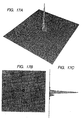
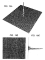
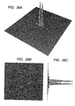
- a stigmatic ideal lens is set by optical calculation and results obtained by calculating point image intensity distributions in the states shown in Figs. 15A, 15B, 15C, 15D and 15E are shown in Figs. 16A, 16B and 16C, 17A, 17B and 17C, 18A, 18B and 18C, 19A, 19B and 19C, and 20A, 20B and 20C.
- 16A, 16B and 16C, 17A, 17B and 17C, 18A, 18B and 18C, 19A, 19B and 19C, and 20A, 20B and 20C show point image intensity distributions in the case where a filter thickness is increased such that a phase difference of transmission wave front in a half region of the diaphragm aperture is increased from (0/4) ⁇ to (4/4) ⁇ in increments of (1/4) ⁇ under a condition of a circular diaphragm in which a wavelength ⁇ of monochromatic light is 550 nm and an F number F is 2.
- a filter thickness is increased such that a phase difference of transmission wave front in a half region of the diaphragm aperture is increased from (0/4) ⁇ to (4/4) ⁇ in increments of (1/4) ⁇ under a condition of a circular diaphragm in which a wavelength ⁇ of monochromatic light is 550 nm and an F number F is 2.
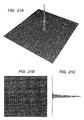
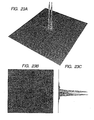
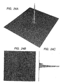
- Figs. 21A, 21B and 21C, 22A, 22B and 22C, 23A, 23B and 23C, 24A, 24B and 24C, and 25A, 25B and 25C show results obtained by calculating point image intensity distributions of while light under the same condition as set in Figs. 16A, 16B and 16C, 17A, 17B and 17C, 18A, 18B and 18C, 19A, 19B and 19C, and 20A, 20B and 20C.
- color weight having a sensitivity peak near 550 nm in a visible light range of 400 nm to 700 nm is set corresponding to spectral luminous efficiency.
- Figs. 23A, 23B and 23C show a state in which the intensity distribution of white light becomes a two-point separate image when the phase difference of transmission wave front is (1/2) ⁇ at the wavelength ⁇ of 550 nm.
- a separate width between the two point separate images is proportional to the F number and the wave length ⁇ , so that the separate width becomes large between two point separate images of red light having a long wavelength, whereas the separate width becomes small between two point separate images of blue light having a short wavelength. Therefore, the two point separate images of white light as shown in Figs. 23A, 23B and 23C becomes an image with color bleeding.
- the intensity of a valley portion located at the midpoint between the two point separate images become zero.
- the intensity of the valley portion does not becomes zero due to the influence of color bleeding.
- the point image intensity distribution becomes not a complete circular form but an elliptical form which is slightly extended in a vertical direction.
- the phase difference of transmission wave front is within a relatively small region of substantially 2 ⁇ or less, the intensity distribution of the imaging point I periodically becomes a single point image or two point images as in the case of monochromatic light.
- the phase difference of transmission wave front is within a large region of several ⁇ or more, a variation in phase difference of transmission wave front due to the wavelength becomes larger so that a behavior different from that in the case of monochromatic light is indicated with respect to.the point image intensity distribution. This will be described below.
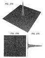
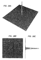
- Figs. 26A, 26B and 26C, 27A, 27B and 27C, 28A, 28B and 28C, and 29A, 29B and 29C show results obtained by calculating a difference between the point image intensity distribution of monochromatic light and that of white light when the phase differences of transmission wave front of 5.5 ⁇ and 6 ⁇ are produced at the wavelength ⁇ of 550 nm.
- Figs. 26A, 26B and 26C show the point image intensity distribution of monochromatic light produced under a condition in which the monochromatic light is used and the phase difference is 5.5 ⁇
- Figs. 27A, 27B and 27C show the point image intensity distribution of white light.
- Figs. 28A, 28B and 28C show the point image intensity distribution of monochromatic light produced under a condition in which the monochromatic light is used and the phase difference is 6 ⁇
- Figs. 29A, 29B and 29C show the point image intensity distribution of white light.
- a region in which the phase difference of transmission wave front is substantially 2 ⁇ or less means a phase difference produced due to a thickness such as that of an optical thin film on an ND filter substrate in a state in which the aperture is completely covered with the ND filter substrate.
- the optical performance is restored somewhat.
- a region in which the phase difference of transmission wave front is 5 ⁇ or more means for example a phase difference produced due to a thickness of an ND filter substrate itself in a state in which the diaphragm aperture is partially covered with an edge portion of the ND filter substrate. In this region, even if the phase difference of transmission wave front is somewhat varied, the optical performance is not greatly changed.
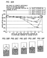
- a relationship between an MTF value used for optical performance evaluation and a phase difference of transmission wave front will be described using Figs. 30A and 30B.
- the influence of diffraction resulting from the transmittance of the ND filter is not considered and the description will be advanced while directing attention only to a change in MTF value according to a phase difference of transmission wave front resulting from a thickness component of the filter.
- Figs. 30A and 30B show wave-optical MTF values of white light in a stigmatic ideal lens system when a filter thickness in a lower half region of a diaphragm aperture is gradually increased from zero to change a phase difference of transmission wave front up to 6 ⁇ .
- Fig. 30A is a graph showing white MTF values at a spatial frequency of 50 lines/mm and Fig. 30B is a graph showing white MTF values at a spatial frequency of 100 lines/mm.
- Respective MTF values in states in which the F numbers of the circular aperture are F1, F1.4, F2, F2.8, F4, F5.6, and F8 are indicated in the graphs.
- a spatial frequency to be evaluated by MTF calculation will be described.
- a threshold spatial frequency resolvable by the image pickup element is 1/(2 ⁇ p).
- a frequency higher than the vicinity of the threshold spatial frequency is cut by a low pass filter because it causes a moiré or a false color signal.
- the spatial frequency important for image quality evaluation is about a half of the threshold frequency of the image pickup element.
- (evaluation spatial frequency) 1/(4 ⁇ p) is defined. Therefore, when the pixel pitch of the image pickup element is 5 ⁇ m, the evaluation spatial frequency is set to 50 lines/mm. In addition, when the pixel pitch is 2.5 ⁇ m, the evaluation spatial frequency is set to 100 lines/mm.
- the evaluation spatial frequency becomes 50 lines/mm.
- the evaluation spatial frequency is converted into a vertical direction television resolution, it corresponds to 270 TV lines.
- the evaluation spatial frequency becomes 100 lines/mm. Also in this case, when the evaluation spatial frequency is converted into the vertical direction television resolution, it corresponds to 270 TV lines.
- a target MTF value at the evaluation spatial frequency is provisionally set to 70% or more. Note that in the MTF calculation performed here, the target MTF value is provisionally set to a somewhat high value because the transmittance of the ND filter is neglected and by considering the fact that a stigmatic ideal lens system is used. However, this value is to be taken only as a guide and not an absolute numerical target.
- the MTF value is kept to 72%.
- the phase difference of transmission wave front becomes (1/2) ⁇
- the MTF value abruptly drops down to 21%.
- the phase difference of transmission wave front is further increased, the MTF value is restored up to 62% in a state where it is 1 ⁇ .
- the MTF value is varied while oscillating.
- the phase difference of transmission wave front is 5 ⁇ or more, the MTF value becomes stable at about 42%.
- the phase difference of transmission wave front is set to the vicinity of substantially zero ⁇ .
- the MTF value is decreased to 45% because of the influence of diffraction.
- the phase difference of transmission wave front is 5 ⁇ or more, the MTF value is decreased to about 5%.
- the phase difference of transmission wave front is 5 ⁇ or more.
- the evaluation spatial frequency is 50 lines/mm, even if the aperture is narrowed down to F4, the MTF value can be kept to 70%.
- the evaluation spatial frequency is 100 lines/mm, unless the aperture is widened up to F2, the MTF value of 70% cannot be attained.
- the ND filter With respect to the ND filter, a type in which an organic coloring matter or pigment absorbing light is mixed in a material and they are kneaded and a type in which an optical thin film is formed on the surface of the material by evaporation have been known.
- the advantage of the kneading type ND filter is that a large number of filters with a uniform density can be processed at a low cost. However, it has wavelength dependency of spectral transmittance which is inferior as compared with the evaporation type ND filter. Thus, for the ND filter used as a diaphragm device for an image taking apparatus, the evaporation type is superior.
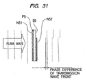
- Fig. 31 shows an example in which the density is set stepwise for a plurality of regions by using an evaporation type ND filter.
- reference symbol P5 denotes an evaporation type ND filter which has two kinds of density regions.
- an ND film N51 is formed on the entire surface of a filter substrate B5 by evaporation and an ND film N52 is formed by evaporation on the rear surface thereof over a region having a different area.
- a phase difference of. transmission wave front resulting from a step formed due to the ND film is produced in an ND evaporation film boundary portion of the rear surface.
- a region in which a phase difference of transmission wave front is 2 ⁇ or less means the case where there is a minute phase difference of transmission wave front resulting from the step due to the film thickness or the like.
- A indicates white MTF calculation values at a spatial frequency of 50 lines/mm when a ratio of putting the boundary region described above on the aperture portion is changed from 0 to 1.0 in increments of 0.1
- B to "F” each indicate a ratio of putting a boundary portion on the aperture portion corresponding to "A”.
- Figs. 32A, 32B, 32C, 32D, 32E and 32F show calculation values when only a density difference is set for regions before and after the boundary and the density difference is set to 0, 0.5, 1.0, and 1.5.
- the density of 0.0 corresponds to the transmittance of 100%
- the density of 0.5 corresponds to the transmittance of 32%
- the density of 1.0 corresponds to the transmittance of 10%
- the density of 1.5 corresponds to the transmittance of 3%.
- the MTF value becomes the minimum when the diaphragm aperture portion is covered with the high density region by 70% to 80%, due to a density difference between regions before and after the boundary. This is because an aperture shape of a low density (high transmittance) portion which is formed by the diaphragm blades and the boundary with a density difference becomes a small diaphragm aperture state and the deterioration of the MTF value is caused by the influence of diffraction.
- the deterioration of the MTF value is less at about a density difference of 0.5. Even in a state in which the diaphragm aperture portion is covered with the high density region by 70% to 80%, 70% or more of a target can be sufficiently kept. On the other hand, when the density difference exceeds 0.5, the MTF value starts to greatly deteriorate. In a state in which the diaphragm aperture portion is covered with the high density region by 70% to 80%, the MTF value is 68% at the density difference of 1.0 and the MTF value is rapidly reduced to 53% at the density difference of 1.5.
- Figs. 33A, 33B, 33C, 33D, 33E and 33F show calculation values in a state in which only a phase difference of transmission wave front is set for regions before and after the boundary and the phase difference is 0 ⁇ , 0.25 ⁇ , 0.5 ⁇ , 6 ⁇ and 0.2 ⁇ .
- the MTF value becomes minimum, due to a phase difference of transmission wave front between regions before and after the boundary, when the diaphragm aperture portion is covered with one region with a predetermined phase difference against the other region with the two regions sandwiching the boundary by just 50% (in a state in which areas of the aperture portion occupied by respective regions before and after the boundary are equal to each other).
- the MTF value is decreased as the phase difference increases.
- a change in MTF value due to a change in phase difference indicates a behavior in which it is periodically changed up to the phase difference of about 2 ⁇ and kept to a substantially constant value in a range of 5 ⁇ or more, as described earlier in Figs. 30A and 30B.
- Figs. 33A, 33B, 33C, 33D, 33E and 33F when the MTF values at phase differences of 0.25 ⁇ and 6 ⁇ are compared, they are substantially equal to each other. This means that, between the case where a phase difference of transmission wave front resulting from a film thickness of an evaporation film is 1/4 ⁇ and the case where a large phase difference of transmission wave front resulting from a thickness of an ND filter substrate is produced, the optical performance is affected to substantially the same degree.
- Figs. 34A, 34B, 34C, 34D, 34E and 34F show MTF calculation values in the case where a density difference of 0.5 and a phase difference of transmission wave front of 0.2 ⁇ are independently set for regions before and after the boundary, and the case where the both are set simultaneously.
- Figs. 34A, 34B, 34C, 34D, 34E and 34F show that, as a result of the synergism, the influence on the optical performance becomes maximum when the aperture portion is covered by about 60% to 70%.
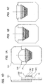
- Embodiment 1 of the present invention is shown in Figs. 1A, 1B, 1C and 1D.
- Figs. 1A, 1B, 1C and 1D show an embodiment of a light quantity adjusting device (diaphragm device) to which the present invention is applied.
- Fig. 1A shows a full open aperture state
- Fig. 1B shows a middle aperture state
- Fig. 1C shows a minimum aperture state
- Fig. 1D is a side view of Fig. 1A.
- reference symbols S11 and S12 denote diaphragm blades for forming a diaphragm aperture and an aperture area can be changed by relatively moving them.
- Reference symbol P1 denotes an ND filter (filter member) which is attached to the diaphragm blade S12 and fixed thereto. Thus, an area of the aperture covered with the ND filter P1 is changed as the diaphragm blades S11 and S12 are relatively moved.
- a smallest transmittance (heavy density) region N13, a second-smallest transmittance (middle transmittance) region N12, and a largest transmittance (light density) region N11 are formed on a substrate B1 in order from the aperture vicinity side of the diaphragm blade S12 to the inside.
- a synthetic resin film made of cellulose acetate, polyethylene terephthalate (PET), vinyl chloride, acrylic resin, or the like is used for the substrate B1.
- a main reason for using the synthetic resin film is used is that specific gravity is light and it is hard to break even in the case of processing into a thin film.
- a thickness of the substrate B1 is about 100 ⁇ m to 50 ⁇ m.
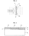
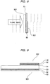
- Fig. 2 shows a state of a transmission wave front passing through the ND filter portion P1.
- respective transmittances are set using the evaporation films such that a density difference between the region N11 and the region N12 and a density difference between the region N12 and the region N13 each become 0.5 or less.
- Film thicknesses of the respective density regions and refraction indexes of materials therefor are set as appropriate so that a phase difference of transmission wave front including a manufacturing error becomes (1/5) ⁇ or less.
- the phase difference of transmission wave front that is (1/5) ⁇ or less corresponds to an actual step (mechanical step) of the respective density regions, which is 0.17 ⁇ m or less.
- the respective regions N11 and N12 of the ND filter P1 have three functional evaporation layers on the film-like substrate B1.
- the region N13 has the ND layer 32 and the AR coat layer 33 without having the base coat layer 31.
- a film thickness of a dielectric film which is made of Al 2 O 3 , SiO 2 , or the like and has a refraction index close to that of the substrate B1 is suitably set and it is formed on the substrate B1 by evaporation to correct the phase difference of transmission wave front.
- the ND layer 32 for reducing the transmittance is made from a multi-layer film and provided so as to reduce wavelength dependency. A thickness of the ND layer 32 is changed to change transmittance for the respective regions N11, N12, and N13. This becomes a main factor for a phase difference of transmission wave front.
- the base coat layer 31 is used for correcting this.
- the AR coat layer 33 for preventing surface reflection is formed as a final layer by evaporation.
- the AR coat layer 33 is obtained by forming a dielectric film made of MgF 2 or the like by evaporation.
- the state in which the edge portion of the ND filter P1 which has a thickness of several ⁇ m or more is located within the diaphragm aperture corresponds to the state in which the phase difference of transmission wave front of 5 ⁇ or more is produced.
- setting is conducted so as to obtain such a state.
- the deterioration of the optical performance is suppressed to a level in which no problem is caused in practice.
- phase difference of transmission wave front becomes (1/5) ⁇ or less, that is, in the vicinity of 0 ⁇ .
- the phase difference of transmission wave front may be set to be in the vicinity of 1 ⁇ or in the vicinity of 2 ⁇ .
- a light quantity adjusting device in which the deterioration of the MTF value can be minimized even in a state in which the aperture is reduced, thereby improving an image quality.
- an image pickup element in which the deterioration of the image quality is suppressed and a pixel pitch is small can be used.
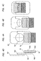
- Embodiment 2 of the present invention is shown in Figs. 4A, 4B, 4C and 4D.
- Figs. 4A, 4B, 4C and 4D show an embodiment of a light quantity adjusting device (diaphragm device) to which the present invention is applied as in Embodiment 1.
- a light quantity adjusting device diaphragm device
- it is different from Embodiment 1, and is an embodiment of a device for separately actuating diaphragm blades and an ND filter to adjust a quantity of light.
- reference symbols S21 and S22 denote diaphragm blades for forming an aperture, and an aperture area can be changed by relatively moving them.
- Reference symbol P2 denotes an ND filter which can be actuated independently from the diaphragm blades S11 and S12.
- a quantity of light is adjusted by reducing the aperture by the diaphragm blades S21 and S22 from an open state shown in Fig. 4A to a predetermined aperture state shown in Fig. 4B. After these states, a quantity of light is adjusted by inserting the ND filter P2 into the aperture in the order from a large transmittance region to a small transmittance region as shown in Fig. 4C while an aperture area is kept constant.
- a region N21 without a light reduction function and a region N22 with predetermined transmittance are formed on one surface of a substrate B2, and a region N23 with the same transmittance as the region N22 and a region N24 with smaller transmittance than those of the regions N22 and N23 are formed on the other surface.
- the transmittance becomes minimum.
- the transmittance becomes the second-smallest.
- the transmittance becomes maximum.
- the ND filter P2 of this embodiment three kinds of transmittances (densities) are set by a combination of evaporation ND films having two kinds of transmittances.
- setting is conducted such that a difference between a density obtaining by combining the regions N21 and N23 and a density obtained by combining the regions N22 and N23, and a difference between a density obtained by combining the regions N22 and N23 and a density obtained by combining the regions N22 and N24 each become 0.5 or less.
- the same substrate as the substrate B1 described in Embodiment 1 is used as the substrate B2.
- Fig. 5 shows a state of a transmission wave front passing through the ND filter portion P2.
- film thicknesses of the regions N21, N22, N23, and N24 and refraction indexes of materials therefor are set as appropriate so that a phase difference of transmission wave front including a manufacturing error becomes (1/5) ⁇ or less (mechanical step becomes 0.17 ⁇ m or less).
- Fig. 6 is an enlarged sectional view of the ND filter P2.
- the respective regions N21, N22, N23, and N24 of this embodiment are also composed of a base coat layer 61, an ND layer 62, and an AR coat layer 63 as in the respective density regions of Embodiment 1.
- This embodiment is characterized in that the region N21 without a light reduction function is composed only of the base coat layer 61 and the AR coat layer 63. Even in this embodiment, a film thickness of the base coat layer 61 is suitably set. Thus, correction is conducted such that the phase difference of transmission wave front in each region becomes (1/5) ⁇ or less.
- materials used for the base coat layer 61, the ND layer 62, and the AR coat layer 63 are the same as in Embodiment 1.
- the phase difference of transmission wave front may be set to be in the vicinity of 1 ⁇ or the vicinity of 2 ⁇ as in Embodiment 1.
- a light quantity adjusting device in which the deterioration of the MTF value can be minimized even in a state in which the aperture is reduced, thereby improving an image quality can be realized as in Embodiment 1.
- an image pickup element in which the deterioration of the image quality is suppressed and a pixel pitch is small can be used.
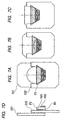
- Embodiment 3 of the present invention is shown in Figs. 7A to 7C.
- Figs. 7A to 7C show an embodiment of a light quantity adjusting device (diaphragm device) to which the present invention is applied as in Embodiment 1.
- Fig. 7A shows a full open aperture state
- Fig. 7B shows a middle aperture state
- Fig. 7C shows a minimum aperture state
- Fig. 7D is a side view of Fig. 7A.
- reference symbols S31 and S32 denote diaphragm blades for forming a diaphragm aperture and an aperture area can be changed by relatively moving them.
- Reference symbol P3 denotes an ND filter (filter member) which is attached to the diaphragm blade S32 and fixed thereto. Thus, an area of the aperture covered with the ND filter P3 is changed as the diaphragm blades S31 and S32 are relatively moved.
- a region N31 with predetermined transmittance is formed on one surface of a substrate B3, and a region N32 with transmittance different from that of the region N31 is formed on a portion of the other surface.
- the transmittances are different. That is, the transmittance in the case where light passes through only the region N31 is smaller.
- a synthetic resin film made of cellulose acetate, polyethylene terephthalate (PET), vinyl chloride, acrylic resin, or the like is used for the substrate B1.
- a main reason for using the synthetic resin film is that specific gravity is small and it is hard to break even in the case of processing into a thin film.
- a thickness of the substrate B3 is about 100 ⁇ m to 50 ⁇ m.
- Fig. 8 shows a state of a transmission wave front passing through the ND filter portion P3.
- respective transmittances are set using the evaporation films.
- Film thicknesses of the respective regions and refraction indexes of materials therefor are set as appropriate so that a phase difference of transmission wave front including a manufacturing error is within a range of ⁇ 1 ⁇ (1/5) ⁇ ⁇ or ⁇ 2 ⁇ (1/5) ⁇ .
- the region N32 of the ND filter P3 has three functional evaporation layers on the film-like substrate B3.
- a base coat layer 91 for setting a phase difference of transmission wave front to a predetermined value ( ⁇ 1 ⁇ (1/5) ⁇ or ⁇ 2 ⁇ (1/5) ⁇
- an ND layer 92 for uniformly reducing transmittance without depending on a wavelength
- an AR coat layer 93 for preventing surface reflection.
- the region N31 is composed only of the ND layer 92 and the AR coat layer 93 without having the base coat layer 91.
- a film thickness of a dielectric film which is made of Al 2 O 3 , SiO 2 , or the like and has a refraction index close to that of the substrate B3 is suitably set and it is formed on the substrate B3 by evaporation to set the phase difference of transmission wave front to the desired value.
- the ND layer 92 for reducing the transmittance is made from a multi-layer film and provided so as to reduce wavelength dependency.
- the ND layer 92 has a minute thickness for setting a desired transmittance (desired density). This becomes a main factor for a phase difference of transmission wave front.
- the base coat layer 91 is used for adjusting this to a suitable phase difference of transmission wave front.
- the AR coat layer 93 for preventing surface reflection is formed as a final layer by evaporation.
- the AR coat layer 93 is obtained by forming a dielectric film made of MgF 2 or the like by evaporation.
- a phase difference of transmission wave front suitable for suppressing the deterioration of the optical performance due to the influence of a minute thickness component is the case where a phase difference of lights with a predetermined wavelength ⁇ is in the vicinity of 0 ⁇ , the vicinity of 1 ⁇ , or the vicinity of 2 ⁇ .
- a range of " ⁇ (1/5) ⁇ ” is assumed as a range of "the vicinity”.
- the phase difference of transmission wave front is set to be in the vicinity of 0 ⁇ ((1/5) ⁇ or less) as described in Embodiments 1 and 2.
- a region for correcting a phase difference of transmission wave front produced therein is provided by a step separated from a step of forming the regions N31 and N32. This means an increase in the number of manufacturing steps so that it leads to a higher cost.
- setting is conducted such that the phase difference of transmission wave front is within a range of ⁇ 1 ⁇ (1/5) ⁇ or ⁇ 2 ⁇ (1/5) ⁇ using a base coat layer 91 which can be formed by a part of a step of forming a film composing the region N32.
- the MTF value is rapidly deteriorated.
- the MTF value is decreased as compared with a state in which the phase difference of transmission wave front of 5 ⁇ or more is produced.
- the deterioration of the MTF value is relatively less as compared with a state in which there is completely no phase difference of transmission wave front.
- the state in which the edge portion of the ND filter P3 which has a thickness of several ⁇ m or more is located within the diaphragm aperture corresponds to the state in which the phase difference of transmission wave front of 5 ⁇ or more is produced.
- setting is conducted so as to obtain such a state.
- the deterioration of the optical performance is suppressed to a level in which no problem is caused in practice.
- a light quantity adjusting device in which the deterioration of the MTF value can be minimized even in a state in which the aperture is reduced, thereby improving an image quality can be realized as in Embodiment 1.
- an image pickup element in which the deterioration of the image quality is suppressed and a pixel pitch is small can be used.
- Embodiment 4 of the present invention is shown in Figs. 10A, 10B, 10C and 10D.
- Figs. 10A, 10B, 10C and 10D show an embodiment of a light quantity adjusting device (diaphragm device) to which the present invention is applied as in Embodiment 1.
- Embodiment 4 is an embodiment of a device for separately actuating diaphragm blades and an ND filter to adjust a quantity of light.
- reference symbols S41 and S42 denote diaphragm blades for forming an aperture and an aperture area can be changed by relatively moving them.
- Reference symbol P4 denotes an ND filter which can be actuated separate from the diaphragm blades S41 and S42.
- a quantity of light is adjusted by reducing the aperture by the diaphragm blades S41 and S42 from an open state shown in Fig. 10A to a predetermined aperture state shown in Fig. 10B. After these states, a quantity of light is adjusted by inserting the ND filter P4 into the aperture in the order from a large transmittance region to a small transmittance region as shown in Fig. 10C while an aperture area is kept constant.
- a region N41 without a light reduction function and a region N42 with predetermined transmittance are formed on one surface of a substrate B4, and a region N43 without a light reduction function and a region N43 with the same transmittance as the region N42 are formed on the other surface.
- the transmittance becomes minimum.
- the transmittance becomes secondly small.
- the transmittance becomes maximum. Therefore, according to the ND filter P4 of this embodiment, three kinds of transmittances (densities) are set by a combination of evaporation ND films having two kinds of transmittances. Note that the same substrate as the substrate B1 described in Embodiment 1 is used as the substrate B4.
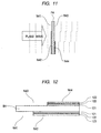
- Fig. 11 shows a state of a transmission wave front passing through the ND filter portion P4.
- film thicknesses of the regions N42 and N44 and refraction indexes of materials therefor are set as appropriate so that a phase difference of transmission wave front including a manufacturing error becomes ⁇ 1 ⁇ (1/5) ⁇ or ⁇ 2 ⁇ (1/5) ⁇ ⁇ .
- Fig. 12 is an enlarged sectional view of the ND filter P4.
- the respective regions N42 and N44 of this embodiment are also composed of a base coat layer 121, an ND layer 122, and an AR coat layer 123 as in the respective density regions of Embodiment 3. Even in this embodiment, a film thickness of the base coat layer 121 is suitably set. Thus, correction is conducted such that the phase difference of transmission wave front of each region becomes in the range of ⁇ 1 ⁇ (1/5) ⁇ or ⁇ 2 ⁇ (1/5) ⁇ . Note that materials used for the base coat layer 121, the ND layer 122, and the AR coat layer 123 are the same as in Embodiment 3.
- a light quantity adjusting device in which the deterioration of the MTF value can be minimized even in a state in which the aperture is reduced, thereby improving an image quality can be realized as in Embodiment 1.
- an image pickup element in which the deterioration of the image quality is suppressed and a pixel pitch is small can be used.
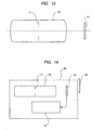
- Fig. 13 is a schematic structure view of an optical system to which the light quantity adjusting device described in Embodiments 1 to 4 is applied.
- reference numeral 10 denotes an image taking optical system composed of a refraction system, a reflection system, a diffraction system, and the like
- 11 denotes a diaphragm for limiting light passing through the optical system 10 to adjust lightness
- 12 denotes a solid image pickup element (photoelectric conversion element) such as a CCD or a CMOS for receiving a subject image formed by the optical system 10 on a light receiving surface and converting it into an electric signal.
- the light quantity adjusting device described in Embodiments 1 to 4 is used for the diaphragm 11.
- the light quantity adjusting device as described in Embodiments 1 to 4 is used as the diaphragm of the optical system such as an image taking optical system, the influence of the ND filter resulting from the phase difference of transmission wave front at the time of narrowing the aperture can be reduced to thereby improve an image quality.
- an image pickup element with a small pixel pitch can be used.
- reference numeral 20 denotes a main body of an image taking apparatus
- 10 denotes an image taking optical system described in Embodiment 5
- 11 denotes a diaphragm composed of the light quantity adjusting device of Embodiments 1 to 4
- 12 denotes a solid image pickup element for receiving a subject image formed by the image taking optical system
- 13 denotes a recording medium for recording the subject image received by the image pickup element 12
- 14 denotes a finder for observing the subject image.
- An optical finder or a finder of a type for observing the subject image displayed on a display element such as a liquid crystal panel is considered as the finder 14.
- Embodiment 5 when the image taking optical system described in Embodiment 5 is applied to an image taking apparatus a type for forming the subject image on the image pickup element such as a video camera or a digital still camera, the influence of the ND filter resulting from the phase difference of transmission wave front can be reduced to thereby improve an image quality.
- an image pickup element with a small pixel pitch can be used.
- the light quantity adjusting device in which the deterioration of the optical performance due to the influence of a minute thickness component of the filter member is suppressed can be realized.
- the light quantity adjusting device of the present invention when used for the image taking optical system of an image taking apparatus for forming an image on an image pickup element, preferable image information can be obtained even if the image pickup element with a small pixel pitch is used.
Landscapes
- Physics & Mathematics (AREA)
- General Physics & Mathematics (AREA)
- Optics & Photonics (AREA)
- Engineering & Computer Science (AREA)
- Multimedia (AREA)
- Signal Processing (AREA)
- Diaphragms For Cameras (AREA)
- Blocking Light For Cameras (AREA)
- Optical Elements Other Than Lenses (AREA)
- Studio Devices (AREA)
Abstract
An optical performance is deteriorated by a minute phase difference of transmission wave front of an ND filter. In a light quantity adjusting device which includes an ND filter (P1) for attenuating a quantity of light passing through an aperture formed by diaphragm blades (S11 and S12) and in which a cover ratio of the aperture by the ND filter (P1) is changed, setting is conducted such that a phase difference between lights with a predetermined wavelength lambda which pass through regions (N11, N12, and N13) of the ND filter (P1) with different transmittances inside the aperture becomes substantially 0 lambda , substantially 1 lambda , or substantially 2 lambda in a state in which the aperture is completely covered with the ND filter (P1). <IMAGE>
Description
The present invention relates to a light
quantity adjusting device suitable for use in an
image taking apparatus such as a video camera or a
digital still camera, and to a technique capable of
suppressing a deterioration of optical performance
even in an image pickup element having a small pixel
pitch.
For an image taking optical system of an image
taking apparatus such as a video camera, a light
quantity adjusting device for changing an aperture
diameter produced by a plurality of diaphragm blades
to adjust a quantity of light is used. In such a
diaphragm apparatus, when the aperture diameter
becomes too small, the deterioration of optical
performance due to light diffraction becomes a
problem.
Therefore, in order to prevent the aperture
diameter from becoming too small even in the case of
an object receiving sufficient light, a light
quantity adjusting device using diaphragm blades in
combination with an ND (neutral density) filter has
been proposed and used in practice.
According to Japanese Patent Publication No.
2592949, a diaphragm apparatus is disclosed in which
an ND filter is bonded to diaphragm blades so as to
be positioned within an aperture formed by the
diaphragm blades and have a plurality of regions for
which uniform transmittance is set, and the
transmittance is set so as to gradually increase from
the outside of the aperture to the inside thereof.
According to Japanese Patent Application Laid-Open
No. 52-117127, a diaphragm apparatus is
disclosed in which mechanical diaphragm blades are
moved during a control from a full open state to a
state with a predetermined aperture area, and in
small aperture control where the aperture is not
larger than a predetermined diaphragm value, an ND
filter whose transmittance is continuously changed
according to the density is entered into the aperture
successively from a filter portion having high
transmittance.
In Japanese Patent Application Laid-Open No.
2000-106649, the influence of transmittance of an ND
filter having a plurality of density regions on an
optical performance is described and an image pickup
apparatus having an exposure control mechanism for
which measures are taken against the influence is
disclosed.
In the cases of these conventional proposals,
with respect to the main factor for the deterioration
of optical performance in a middle aperture state
between a full open aperture state and a small
aperture state, it is considered that the influence
of diffraction due to a difference of the
transmittance of the ND filter covering the aperture
portion produced by the diaphragm blades is dominant.
Thus, in the case of the ND filter having a plurality
of density regions, measures against the influence of
diffraction have been proposed with attention to
transmittances and areas of the respective regions of
the ND filter.
On the other hand, with respect to a factor for
the deterioration of optical performance in the
middle aperture state, there is not only the
influence of diffraction due to a difference of the
transmittance of the ND filter but also the influence
of a phase difference of transmission wave front
resulting from a thickness component of the ND filter.
It has been experimentally known that an
optical performance is deteriorated when a part of a
diaphragm aperture portion is covered with a filter
having a thickness. However, there is known no
example in which it is examined as to how the optical
performance is influenced by a filter thickness
component and specific countermeasures are taken
therefor.
According to Japanese Patent Application Laid-Open
No. 06-265971, a structure in which an ND filter
having a transparent portion and a portion in which
transmittance is changed continuously or stepwise is
moved in a state in which it covers the entire fixed
circular diaphragm aperture, thereby adjusting a
quantity of light transmitted, has been proposed as a
measure for avoiding the influence of the thickness
of the ND filter on the optical performance.
However, the invention according to Japanese
Patent Application Laid-Open No. 06-265971 focuses
attention on only a large phase difference between a
portion in which light passes through a filter member
and a portion in which light does not pass through
the filter member. Thus, there is no suggestion as
to the problem of, and measures against, a minute
phase difference of transmission wave front up to
about two times larger than a wavelength of light λ,
which results from a change in minute thickness or a
change in minute refractive index which will occur in
order to provide a change in transmittance when
actually realizing an ND filter in which
transmittance is changed. According to a study by
the present inventor(s), it was found that a minute
phase difference of transmission wave front of no
more than the order of wavelength of light has a very
large influence on the optical performance under
certain conditions.
Also, it was found that there is a difference
between how the influence of the phase difference of
transmission wave front on the optical performance
appears and how the influence of a density difference
between adjacent regions of the ND filter with
different transmittances on the optical performance
appears, thus greatly affecting the optical
performance under certain conditions by the synergism
of the two components, namely the phase difference of
transmission wave front and the density difference.
Therefore, an object of the present invention
is to suppress a deterioration of optical performance
due to the influence of a minute thickness component
of a filter member in a light quantity adjusting
device for adjusting a quantity of light using a
diaphragm in combination with the filter member for
attenuating transmitted light such as an ND filter.
In order to achieve the above object, according
to a first aspect of the present invention, in a
light quantity adjusting device which includes a
diaphragm for forming an aperture and a filter member
for attenuating a quantity of light passing through
the aperture of the diaphragm and in which a cover
ratio of the aperture by the filter member is changed,
in a state in which the aperture is completely
covered with the filter member, setting is conducted
such that a phase difference between lights with a
predetermined wavelength λ which pass through
positions of the filter member with different
transmittances becomes substantially 0λ,
substantially 1λ, or substantially 2λ.
Here, "the predetermined wavelength" in the
first aspect of the present invention is set as
appropriate according to a usage state of the light
quantity adjusting device. For example, when a
center wavelength of a usage wavelength band is used
and a visible light region is the usage wavelength
band, λ = 550 nm is preferable.
In addition, the phase difference of
"substantially 0λ, substantially 1λ, or
substantially 2λ" means that a phase difference
including a manufacturing error is in a range of {0±
(1/5)}λ, {1±(1/5)}λ, or {2±(1/5)}λ. If the phase
difference is within this range, it is assumed to be
a phase difference of substantially 0λ, 1λ, or 2λ,
thus adequately achieving an initial object of the
present invention.
Also, according to a second aspect of the
present invention, in a light quantity adjusting
device which includes a diaphragm for forming an
aperture and a filter member for attenuating a
quantity of light passing through the aperture of the
diaphragm and in which a cover ratio of the aperture
by the filter member is changed, the device comprises
means for setting to a predetermined value a phase
difference between lights which pass through
positions of the filter member with different
transmittances, in a state in which the aperture is
completely covered with the filter member.
The light quantity adjusting device according
to the first to third aspects of the present
invention is suitably used for adjusting the quantity
of light passing through an optical system, and
suitable for use in an optical system of an image
taking apparatus for forming an image on an image
pickup element (photoelectric conversion element)
such as a CCD or a CMOS in particular.
In the accompanying drawings:
Before the description of a light quantity
adjusting device (diaphragm device) of this
embodiment mode, an influence of a phase difference
of transmission wave front on an image will be
described.
First, an optical phenomenon produced when a
part of a diaphragm aperture portion is covered with
a filter having a thickness will be described using
Figs. 15A, 15B, 15C, 15D and 15E.
Figs. 15A, 15B, 15C, 15D and 15E show point
image intensity distributions Q around a geometrical-optical
imaging point I when is a filter P and an
aperture diaphragm S are located in front (the object
side) of a stigmatic ideal lens L and a parallel
light beam which is a plane wave of monochromatic
light with a wavelength λ is incident.
Fig. 15A shows a state in which a thickness of
the filter P is zero and a transmission wave front is
not influenced thereby. In this case, the intensity
distribution Q becomes a diffraction pattern
according to a relationship between an F number F and
the wavelength λ of a light beam (reference: "Wave
Front Optics for Lens Design", Tohru Kusakawa, Tokai
University Press).
When the diaphragm S is a circular aperture, a
single point image with a radius of 1.22 Fλ is
imaged and a diffraction light pattern of ring-shaped
weak light is formed in its vicinities. Here, when a
thickness of a region (lower side in the drawing) of
the filter P corresponding to a half of the aperture
produced by the diaphragm S is increased by a minute
quantity and setting is conducted such that a phase
difference of transmission wave front becomes (1/4)λ
as shown in Fig. 15B, a point image with a small
intensity appears beside the point image with a
strong intensity.
When the thickness of the lower side region of
the filter P is further increased and setting is
conducted such that the phase difference of
transmission wave front becomes (2/4)λ as shown in
Fig. 15C, the intensity distribution Q does not
become a single point image but becomes an intensity
distribution including two point images which are
separated from each other in a vertical direction in
the drawing. This is because, of lights focused into
the geometrical-optical imaging point I, a phase of a
wave front of light passing through an upper side
half region of pupil in the drawing is shifted from
that of a wave front of light passing through a lower
side half region in the drawing by (1/2)λ, thereby
producing a wave-optical canceling phenomenon of
waves so that the intensity on the imaging point I
becomes zero. On the other hand, there are no cases
where energies of lights to be focused into the
imaging point I are lost because of the conservation
of energy. Thus, they are dispersed in a vertical
direction in the drawing with respect to the imaging
point I and converged at two points.
When the thickness of the lower side region of
the filter P is further increased and setting is
conducted such that the phase difference of
transmission wave front becomes (3/4)λ as shown in
Fig. 15D, the intensity of an upper side image of the
two point images becomes weaker and the intensity of
an lower side image becomes stronger.
When the thickness of the lower side region of
the filter P is further increased and setting is
conducted such that the phase difference of
transmission wave front becomes (4/4)λ as shown in
Fig. 15E, the intensity distribution Q becomes a
diffraction pattern of a single point image again so
that it is returned to the same state as in Fig. 15A.
When the thickness of the lower side region of
the filter P is further increased, a change in
intensity distribution Q is periodically repeated
according to the phase difference of the transmission
wave front.
With respect to an interval Δy between the two
point images which are separated from each other at
the time when the phase difference of transmission
wave front is (1/2)λ as shown in Fig. 15C, there is
a relationship of Δy ≅ 2Fλ, and it is proportional
to an F number and a wavelength λ. For example, in
the case of the F number F = 4 and the wavelength λ
= 550 nm, the interval Δy between the two point
images becomes approximately 4.4. This means that,
according to the same principle as a two-point
separate low pass filter, there is produced the same
effect as in the case of using a low pass filter with
a cutoff frequency of 1/(2Δy) = 114 lines/mm, and an
MTF of an optical system is deteriorated.
A stigmatic ideal lens is set by optical
calculation and results obtained by calculating point
image intensity distributions in the states shown in
Figs. 15A, 15B, 15C, 15D and 15E are shown in Figs.
16A, 16B and 16C, 17A, 17B and 17C, 18A, 18B and 18C,
19A, 19B and 19C, and 20A, 20B and 20C. Figs. 16A,
16B and 16C, 17A, 17B and 17C, 18A, 18B and 18C, 19A,
19B and 19C, and 20A, 20B and 20C show point image
intensity distributions in the case where a filter
thickness is increased such that a phase difference
of transmission wave front in a half region of the
diaphragm aperture is increased from (0/4)λ to (4/4)
λ in increments of (1/4)λ under a condition of a
circular diaphragm in which a wavelength λ of
monochromatic light is 550 nm and an F number F is 2.
In Figs. 16A, 16B and 16C, 17A, 17B and 17C, 18A, 18B
and 18C, 19A, 19B and 19C, and 20A, 20B and 20C,
symbols "A", "B", and "C" indicate a bird's-eye view,
a plan view and a side view of the point image
intensity distribution, respectively (Figs. 21A, 21B
and 21C, 22A, 22B and 22C, 23A, 23B and 23C, 24A, 24B
and 24C, 25A, 25B and 25C, 26A, 26B and 26C, 27A, 27B
and 27C, 28A, 28B and 28C, and 29A, 29B and 29C which
are shown later are also the same).
It is also found from Figs. 16A, 16B and 16C,
17A, 17B and 17C, 18A, 18B and 18C, 19A, 19B and 19C,
and 20A, 20B and 20C that, in the case of
monochromatic light with a single wavelength, the
intensity distribution of the imaging point I is
periodically changed according to the phase
difference of transmission wave front which occurs
due to a change in filter thickness.
Now, light actually used for an image taking
system is not monochromatic light but white light in
which lights having various wavelengths are mixed.
Figs. 21A, 21B and 21C, 22A, 22B and 22C, 23A, 23B
and 23C, 24A, 24B and 24C, and 25A, 25B and 25C show
results obtained by calculating point image intensity
distributions of while light under the same condition
as set in Figs. 16A, 16B and 16C, 17A, 17B and 17C,
18A, 18B and 18C, 19A, 19B and 19C, and 20A, 20B and
20C. Note that, for while light, color weight having
a sensitivity peak near 550 nm in a visible light
range of 400 nm to 700 nm is set corresponding to
spectral luminous efficiency.
With respect to a change in point image
intensity distribution when the phase difference of
transmission wave front is zero λ to 1λ at the
wavelength λ of 550 nm, it is found from Figs. 21A,
21B and 21C, 22A, 22B and 22C, 23A, 23B and 23C, 24A,
24B and 24C, and 25A, 25B and 25C that also in the
case of while light, a single point image is divided
into two and then the two point images are changed
again into a single point image substantially in the
same manner as in the case of monochromatic light.
Figs. 23A, 23B and 23C show a state in which
the intensity distribution of white light becomes a
two-point separate image when the phase difference of
transmission wave front is (1/2)λ at the wavelength
λ of 550 nm. As described earlier, a separate width
between the two point separate images is proportional
to the F number and the wave length λ, so that the
separate width becomes large between two point
separate images of red light having a long wavelength,
whereas the separate width becomes small between two
point separate images of blue light having a short
wavelength. Therefore, the two point separate images
of white light as shown in Figs. 23A, 23B and 23C
becomes an image with color bleeding. In the case of
monochromatic light, the intensity of a valley
portion located at the midpoint between the two point
separate images become zero. However, in the case of
white light, the intensity of the valley portion does
not becomes zero due to the influence of color
bleeding.
Figs. 25A, 25B and 25C show the point image
intensity distribution of white light when the phase
difference of transmission wave front is just (4/4)λ
= 1λ at the wavelength λ of 550 nm. A phase
difference of lights passing through the filter is
changed according to the wavelength and phase
differences among all wavelengths of white light do
not become 1λ. Thus, as is apparent from Fig. 25B,
the point image intensity distribution becomes not a
complete circular form but an elliptical form which
is slightly extended in a vertical direction.
Thus, in the case of while light, if the phase
difference of transmission wave front is within a
relatively small region of substantially 2λ or less,
the intensity distribution of the imaging point I
periodically becomes a single point image or two
point images as in the case of monochromatic light.
However, if the phase difference of transmission wave
front is within a large region of several λ or more,
a variation in phase difference of transmission wave
front due to the wavelength becomes larger so that a
behavior different from that in the case of
monochromatic light is indicated with respect to.the
point image intensity distribution. This will be
described below.
Figs. 26A, 26B and 26C, 27A, 27B and 27C, 28A,
28B and 28C, and 29A, 29B and 29C show results
obtained by calculating a difference between the
point image intensity distribution of monochromatic
light and that of white light when the phase
differences of transmission wave front of 5.5λ and 6
λ are produced at the wavelength λ of 550 nm.
Figs. 26A, 26B and 26C show the point image
intensity distribution of monochromatic light
produced under a condition in which the monochromatic
light is used and the phase difference is 5.5λ, and
Figs. 27A, 27B and 27C show the point image intensity
distribution of white light.
Figs. 28A, 28B and 28C show the point image
intensity distribution of monochromatic light
produced under a condition in which the monochromatic
light is used and the phase difference is 6λ, and
Figs. 29A, 29B and 29C show the point image intensity
distribution of white light.
In the case of the monochromatic light and the
phase difference of transmission wave front of 5.5λ,
a phase is shifted by (1/2) as shown in Figs. 26A,
26B and 26C. Thus, as in the case of Figs. 18A, 18B
and 18C, the intensity distribution including two
separated point images is obtained. However, the two
point images are not obtained in the case of white
light. In the other words, not all the phase
differences between the respective wavelengths
become a (1/2) phase and a phase difference becomes
larger according to the wavelength. Therefore, the
intensity distribution of a single point image with
an elliptical form extended in a direction in which a
phase difference is produced (vertical direction in
Figs. 27A, 27B and 27C) is obtained as shown in Figs.
27A, 27B and 27C.
Next, when the case of the phase difference of
transmission wave front of 6λ is examined, phases
are just matched in the case of monochromatic light.
Thus, the intensity distribution of a single point
image with a circular form is obtained as shown in
Figs. 28A, 28B and 28C. In the case of white light,
the intensity distribution with an elliptical form
extended in a direction in which a phase difference
is produced (vertical direction in Figs. 29A, 29B and
29C) is obtained as shown in Figs. 29A, 29B and 29C.
When the intensity distribution shown in Figs.
27A, 27B and 27C is compared with that shown in Figs.
29A, 29B and 29C, it is apparent that, in the case of
white light, there is almost no change in the point
image intensity distribution even if the phase
difference of transmission wave front is changed from
5.5λ to 6λ. This indicates that in the case of
white light, the influence of the phase difference of
transmission wave front on an optical performance
greatly differs between the case where the phase
difference of transmission wave front at a pupil
plane which is a diaphragm aperture is small at
substantially 2λ or less and the case where it is
larger at 5λ or more.
In a light quantity adjusting device using an
ND filter, a region in which the phase difference of
transmission wave front is substantially 2λ or less
means a phase difference produced due to a thickness
such as that of an optical thin film on an ND filter
substrate in a state in which the aperture is
completely covered with the ND filter substrate. In
this region, when the phase difference of
transmission wave front is changed from iλ (i = 0,
1) to (i+(1/2))λ, the optical performance is rapidly
deteriorated. When it is changed from (i+(1/2))λ to
(i+1)λ, the optical performance is restored somewhat.
On the other hand, a region in which the phase
difference of transmission wave front is 5λ or more
means for example a phase difference produced due to
a thickness of an ND filter substrate itself in a
state in which the diaphragm aperture is partially
covered with an edge portion of the ND filter
substrate. In this region, even if the phase
difference of transmission wave front is somewhat
varied, the optical performance is not greatly
changed.
In relation to this, a relationship between an
MTF value used for optical performance evaluation and
a phase difference of transmission wave front will be
described using Figs. 30A and 30B. Here, the
influence of diffraction resulting from the
transmittance of the ND filter is not considered and
the description will be advanced while directing
attention only to a change in MTF value according to
a phase difference of transmission wave front
resulting from a thickness component of the filter.
Figs. 30A and 30B show wave-optical MTF values
of white light in a stigmatic ideal lens system when
a filter thickness in a lower half region of a
diaphragm aperture is gradually increased from zero
to change a phase difference of transmission wave
front up to 6λ.
Fig. 30A is a graph showing white MTF values at
a spatial frequency of 50 lines/mm and Fig. 30B is a
graph showing white MTF values at a spatial frequency
of 100 lines/mm. The ordinate of the graph indicates
an MTF value and the abscissa indicates a phase
difference of transmission wave front at a wavelength
λ = 550 nm. Respective MTF values in states in which
the F numbers of the circular aperture are F1, F1.4,
F2, F2.8, F4, F5.6, and F8 are indicated in the
graphs.
Here, a spatial frequency to be evaluated by
MTF calculation will be described. When a pixel
pitch of an image pickup element is "p" µm, a
threshold spatial frequency resolvable by the image
pickup element is 1/(2×p). Generally, a frequency
higher than the vicinity of the threshold spatial
frequency is cut by a low pass filter because it
causes a moiré or a false color signal. The spatial
frequency important for image quality evaluation is
about a half of the threshold frequency of the image
pickup element.
Thus, (evaluation spatial frequency) = 1/(4×p)
is defined. Therefore, when the pixel pitch of the
image pickup element is 5 µm, the evaluation spatial
frequency is set to 50 lines/mm. In addition, when
the pixel pitch is 2.5 µm, the evaluation spatial
frequency is set to 100 lines/mm.
For example, in the case of an image pickup
element for video camera in which the number of
effective pixels is 380,000 and a screen diagonal
size of a light receiving element is 4.5 mm, when the
pixel pitch is about 5 µm, the evaluation spatial
frequency becomes 50 lines/mm. When the evaluation
spatial frequency is converted into a vertical
direction television resolution, it corresponds to
270 TV lines. In the case of an image pickup element
in which the number of effective pixels is the same
and the screen diagonal size of the light receiving
element is 2.25 mm, when the pixel pitch is about 2.5
µm, the evaluation spatial frequency becomes 100
lines/mm. Also in this case, when the evaluation
spatial frequency is converted into the vertical
direction television resolution, it corresponds to
270 TV lines.
Now, the description will return to the
influence of the phase difference of transmission
wave front on the optical performance.
A target MTF value at the evaluation spatial
frequency is provisionally set to 70% or more. Note
that in the MTF calculation performed here, the
target MTF value is provisionally set to a somewhat
high value because the transmittance of the ND filter
is neglected and by considering the fact that a
stigmatic ideal lens system is used. However, this
value is to be taken only as a guide and not an
absolute numerical target.
First, a description will be made with respect
to a white MTF value at the spatial frequency of 50
lines/mm as shown in Fig. 30A.
When the phase difference of transmission wave
front is zero λ in a state in which the aperture is
narrowed down to F8, the MTF value is kept to 72%.
However, when the phase difference of transmission
wave front becomes (1/2)λ, the MTF value abruptly
drops down to 21%. When the phase difference of
transmission wave front is further increased, the MTF
value is restored up to 62% in a state where it is 1
λ. When the phase difference of transmission wave
front is further increased, the MTF value is varied
while oscillating. When the phase difference of
transmission wave front is 5λ or more, the MTF value
becomes stable at about 42%. In order to satisfy a
target MTF value in a state of F8, it is required
that the phase difference of transmission wave front
is set to the vicinity of substantially zero λ.
In a state of F5.6, when the phase difference
of transmission wave front is zero λ, the MTF value
is kept to 80%. However, when the phase difference
of transmission wave front is (1/2)λ, the MTF value
is decreased to 44%. When the phase difference of
transmission wave front is 1λ, the MTF value is
restored up to 76%. After that, while the MTF value
is oscillated, it becomes stable at about 61% when
the phase difference of transmission wave front is 5
λ or more.
In a state of F4, when the phase difference of
transmission wave front is zero λ, the MTF value is
85%. When the phase difference of transmission wave
front is (1/2)λ, the MTF value is decreased to 58%.
When the phase difference of transmission wave front
is 1λ, the MTF value is restored up to 82%. After
that, while the MTF value is oscillated, it becomes
stable at about 72% when the phase difference of
transmission wave front is 5λ or more.
In a state of F2.8, when the phase difference
of transmission wave front is zero λ, the MTF value
is kept to 90%. In addition, even when the phase
difference of transmission wave front is (1/2)λ, the
MTF value is kept to 71%. When the phase difference
of transmission wave front is 1λ, the MTF value is
restored up to 88%. After that, while the MTF value
is oscillated, it become stable at about 80% when the
phase difference of transmission wave front is 5λ or
more.
In the case of a diaphragm aperture state
allowing higher light level than F2.8, the MTF value
never drops below 70% due to the influence of the
phase difference of transmission wave front.
Next, white MTF values at a spatial frequency
of 100 lines/mm as shown in Fig. 30B will be
described.
In the case of a state in which the aperture is
narrowed down to F8, the MTF value is decreased to
45% because of the influence of diffraction. When
the phase difference of transmission wave front is 5
λ or more, the MTF value is decreased to about 5%.
Thus, in a state of F8, it is impossible to satisfy a
target MTF value.
In a state of F5.6, when the phase difference
of transmission wave front is zero λ, the MTF value
is decreased to 61%. In addition, when the phase
difference of transmission wave front is (1/2)λ, the
MTF value is decreased to 6%. When the phase
difference of transmission wave front is 1λ, the MTF
value is restored up to 53%. After that, while the
MTF value is oscillated, it becomes stable at about
27% when the phase difference of transmission wave
front is 5λ or more. Even in the state of F5.6, the
influence of diffraction is large so that the target
MTF value cannot be satisfied.
In a state of F4, when the phase difference of
transmission wave front is zero λ, the MTF value is
kept to 72%. However, when the phase difference of
transmission wave front is (1/2)λ, the MTF value is
decreased to 21%. When the phase difference of
transmission wave front is 1λ, the MTF value is
restored up to 66%. After that, while the MTF value
is oscillated, it becomes stable at about 45% when
the phase difference of transmission wave front is 5
λ or more. In order to satisfy the target MTF value
in a state of F4, it is required that the phase
difference of transmission wave front is set to the
vicinity of zero λ. Thus, when the ND filter is
moved within the diaphragm aperture state of F4, a
large phase difference of transmission wave front is
produced due to the thickness of the filter so that
the target MTF value cannot be satisfied.
In a state of F2.8, when the phase difference
of transmission wave front is zero λ, the MTF value
is kept to 80%. However, when the phase difference
of transmission wave front is (1/2)λ, the MTF value
is decreased to 43%. When the phase difference of
transmission wave front is 1λ, the MTF value is
restored up to 76%. After that, while the MTF value
is oscillated, it becomes stable at about 60% when
the phase difference of transmission wave front is 5
λ or more.
In a state of F2, when the phase difference of
transmission wave front is zero λ, the MTF value is
kept to 85%. However, when the phase difference of
transmission wave front is (1/2)λ, the MTF value is
decreased to 58%. When the phase difference of
transmission wave front is 1λ, the MTF value is
restored up to 73%. After that, while the MTF value
is oscillated, it becomes stable at about 71% when
the phase difference of transmission wave front is 5
λ or more.
In a state of F1.4, when the phase difference
of transmission wave front is zero λ, the MTF value
is kept to 90%. However, when the phase difference
of transmission wave front is (1/2)λ, the MTF value
is decreased to 70%. When the phase difference of
transmission wave front is 1λ, the MTF value is
restored up to 88%. After that, while the MTF value
is oscillated, it becomes stable at about 89% when
the phase difference of transmission wave front is 5
λ or more.
In a state where the filter is moved into the
diaphragm aperture portion and the filter edge
portion is located in the central portion of the
aperture, the phase difference of transmission wave
front is 5λ or more. In this state of the phase
difference of transmission wave front, when the
evaluation spatial frequency is 50 lines/mm, even if
the aperture is narrowed down to F4, the MTF value
can be kept to 70%. On the other hand, when the
evaluation spatial frequency is 100 lines/mm, unless
the aperture is widened up to F2, the MTF value of
70% cannot be attained.
With respect to the ND filter, a type in which
an organic coloring matter or pigment absorbing light
is mixed in a material and they are kneaded and a
type in which an optical thin film is formed on the
surface of the material by evaporation have been
known. The advantage of the kneading type ND filter
is that a large number of filters with a uniform
density can be processed at a low cost. However, it
has wavelength dependency of spectral transmittance
which is inferior as compared with the evaporation
type ND filter. Thus, for the ND filter used as a
diaphragm device for an image taking apparatus, the
evaporation type is superior. For the evaporation
type ND filter, less wavelength dependency of
spectral transmittance and a function as an
antireflection film can be provided by laminating a
plurality of metallic films or dielectric films
(Reference: "Design, manufacturing, and Evaluation
Technique for Optical Thin Film", Technical
Information Association).
Fig. 31 shows an example in which the density
is set stepwise for a plurality of regions by using
an evaporation type ND filter. In the drawing,
reference symbol P5 denotes an evaporation type ND
filter which has two kinds of density regions.
According to this example, an ND film N51 is formed
on the entire surface of a filter substrate B5 by
evaporation and an ND film N52 is formed by
evaporation on the rear surface thereof over a region
having a different area. In this case, as shown in
the drawing, a phase difference of. transmission wave
front resulting from a step formed due to the ND film
is produced in an ND evaporation film boundary
portion of the rear surface.
In Figs. 30A and 30B, a region in which a phase
difference of transmission wave front is 2λ or less
means the case where there is a minute phase
difference of transmission wave front resulting from
the step due to the film thickness or the like.
Next, the influence of a density difference on
an optical performance, the influence of a phase
difference of transmission wave front on the optical
performance, and the influence of the synergism of
both the density difference and the phase difference
of transmission wave front on the optical performance
will be described with respect to the case where the
diaphragm aperture portion is gradually covered with
the ND filter.
As a simplified model, assumed is a state in
which a stigmatic ideal lens is used and the
diaphragm aperture portion has a shape in which a
square is slanted by 45 degrees, and the aperture is
reduced to F4. A boundary with a density difference,
a boundary where a phase difference of transmission
wave front is produced, or a boundary where the both
are present in the ND filter is continuously moved
relative to the diaphragm aperture so that a state in
which the diaphragm aperture is covered with a high
density (low transmittance) region, a region with a
predetermined thickness, or a region with both is set
on calculation. In Figs. 32A, 32B, 32C, 32D, 32E and
32F, 33A, 33B, 33C, 33D, 33E and 33F, 34A, 34B, 34C,
34D, 34E and 34F, "A" indicates white MTF calculation
values at a spatial frequency of 50 lines/mm when a
ratio of putting the boundary region described above
on the aperture portion is changed from 0 to 1.0 in
increments of 0.1, and "B" to "F" each indicate a
ratio of putting a boundary portion on the aperture
portion corresponding to "A".
Figs. 32A, 32B, 32C, 32D, 32E and 32F show
calculation values when only a density difference is
set for regions before and after the boundary and the
density difference is set to 0, 0.5, 1.0, and 1.5.
Here, a relationship between the density and the
transmittance is "(density) = -log (transmittance)".
Thus,
the density of 0.0 corresponds to the transmittance of 100%,
the density of 0.5 corresponds to the transmittance of 32%,
the density of 1.0 corresponds to the transmittance of 10%, and
the density of 1.5 corresponds to the transmittance of 3%.
the density of 0.0 corresponds to the transmittance of 100%,
the density of 0.5 corresponds to the transmittance of 32%,
the density of 1.0 corresponds to the transmittance of 10%, and
the density of 1.5 corresponds to the transmittance of 3%.
It is apparent that the MTF value becomes the
minimum when the diaphragm aperture portion is
covered with the high density region by 70% to 80%,
due to a density difference between regions before
and after the boundary. This is because an aperture
shape of a low density (high transmittance) portion
which is formed by the diaphragm blades and the
boundary with a density difference becomes a small
diaphragm aperture state and the deterioration of the
MTF value is caused by the influence of diffraction.
Also, the deterioration of the MTF value is
less at about a density difference of 0.5. Even in a
state in which the diaphragm aperture portion is
covered with the high density region by 70% to 80%,
70% or more of a target can be sufficiently kept. On
the other hand, when the density difference exceeds
0.5, the MTF value starts to greatly deteriorate. In
a state in which the diaphragm aperture portion is
covered with the high density region by 70% to 80%,
the MTF value is 68% at the density difference of 1.0
and the MTF value is rapidly reduced to 53% at the
density difference of 1.5.
Figs. 33A, 33B, 33C, 33D, 33E and 33F show
calculation values in a state in which only a phase
difference of transmission wave front is set for
regions before and after the boundary and the phase
difference is 0λ, 0.25λ, 0.5λ, 6λ and 0.2λ.
It is apparent that the MTF value becomes
minimum, due to a phase difference of transmission
wave front between regions before and after the
boundary, when the diaphragm aperture portion is
covered with one region with a predetermined phase
difference against the other region with the two
regions sandwiching the boundary by just 50% (in a
state in which areas of the aperture portion occupied
by respective regions before and after the boundary
are equal to each other). In addition, in the state
of 50% coverage, when the cases where the phase
difference is 0λ, 0.25λ, and 0.5λ are compared, the
MTF value is decreased as the phase difference
increases. Thus, a change in MTF value due to a
change in phase difference indicates a behavior in
which it is periodically changed up to the phase
difference of about 2λ and kept to a substantially
constant value in a range of 5λ or more, as
described earlier in Figs. 30A and 30B.
In Figs. 33A, 33B, 33C, 33D, 33E and 33F, when
the MTF values at phase differences of 0.25λ and 6λ
are compared, they are substantially equal to each
other. This means that, between the case where a
phase difference of transmission wave front resulting
from a film thickness of an evaporation film is 1/4λ
and the case where a large phase difference of
transmission wave front resulting from a thickness of
an ND filter substrate is produced, the optical
performance is affected to substantially the same
degree.
Next, the influence of the synergism of both a
density difference and a phase difference of
transmission wave front between regions before and
after the boundary on the optical performance will be
described.
Figs. 34A, 34B, 34C, 34D, 34E and 34F show MTF
calculation values in the case where a density
difference of 0.5 and a phase difference of
transmission wave front of 0.2λ are independently
set for regions before and after the boundary, and
the case where the both are set simultaneously.
As described above, the influence of the
density difference on the MTF value becomes maximum
when the diaphragm aperture portion is covered with
the high density region by 70% to 80%. On the other
hand, the influence of the phase difference of
transmission wave front on the MTF value is maximized
in a state in which areas of the aperture portion
occupied by regions before and after the boundary are
equal to each other. When such two conditions are
simultaneously produced, Figs. 34A, 34B, 34C, 34D,
34E and 34F show that, as a result of the synergism,
the influence on the optical performance becomes
maximum when the aperture portion is covered by about
60% to 70%.
As described above using Figs. 32A, 32B, 32C,
32D, 32E and 32F, 33A, 33B, 33C, 33D, 33E and 33F,
and 34A, 34B, 34C, 34D, 34E and 34F, even when only
the density difference of the regions before and
after the boundary is suppressed to be small, if the
phase difference is large, the optical performance is
deteriorated. Alternatively, when only the phase
difference is suppressed to be small, if the density
difference is large, the optical performance is
deteriorated. Thus, in order to minimize the
deterioration of the optical performance, it is
necessary to set the phase difference of transmission
wave front and the density difference in a balanced
manner.
In the following specific embodiments of the
invention, there will be disclosed a structure for
keeping the phase difference of transmission wave
front and/or the density difference between adjacent
regions in a suitable range to minimize the
deterioration of the optical performance.
In the drawings, reference symbols S11 and S12
denote diaphragm blades for forming a diaphragm
aperture and an aperture area can be changed by
relatively moving them. Reference symbol P1 denotes
an ND filter (filter member) which is attached to the
diaphragm blade S12 and fixed thereto. Thus, an area
of the aperture covered with the ND filter P1 is
changed as the diaphragm blades S11 and S12 are
relatively moved. In addition, with respect to the
ND filter P1, a smallest transmittance (heavy
density) region N13, a second-smallest transmittance
(middle transmittance) region N12, and a largest
transmittance (light density) region N11 are formed
on a substrate B1 in order from the aperture vicinity
side of the diaphragm blade S12 to the inside. A
synthetic resin film made of cellulose acetate,
polyethylene terephthalate (PET), vinyl chloride,
acrylic resin, or the like is used for the substrate
B1. A main reason for using the synthetic resin film
is used is that specific gravity is light and it is
hard to break even in the case of processing into a
thin film. A thickness of the substrate B1 is about
100 µm to 50 µm.
Fig. 2 shows a state of a transmission wave
front passing through the ND filter portion P1. With
respect to the respective density regions N11, N12,
and N13 in Fig. 2, respective transmittances are set
using the evaporation films such that a density
difference between the region N11 and the region N12
and a density difference between the region N12 and
the region N13 each become 0.5 or less. Film
thicknesses of the respective density regions and
refraction indexes of materials therefor are set as
appropriate so that a phase difference of
transmission wave front including a manufacturing
error becomes (1/5)λ or less. When the ND filter
((average refraction index of multi-layer film) ≅
1.63) disclosed in JP 07-063915 A is assumed, the
phase difference of transmission wave front that is
(1/5)λ or less corresponds to an actual step
(mechanical step) of the respective density regions,
which is 0.17 µm or less.
As shown in Fig. 3, the respective regions N11
and N12 of the ND filter P1 have three functional
evaporation layers on the film-like substrate B1. In
other words, there are a base coating layer 31 for
correcting a phase difference of transmission wave
front, an ND layer 32 for uniformly reducing
transmittance without depending on a wavelength, and
an AR coating layer 33 for preventing surface
reflection. The region N13 has the ND layer 32 and
the AR coat layer 33 without having the base coat
layer 31.
With respect to the base coat layer 31 for
correcting the phase difference of transmission wave
front, a film thickness of a dielectric film which is
made of Al2O3, SiO2, or the like and has a refraction
index close to that of the substrate B1 is suitably
set and it is formed on the substrate B1 by
evaporation to correct the phase difference of
transmission wave front. The ND layer 32 for
reducing the transmittance is made from a multi-layer
film and provided so as to reduce wavelength
dependency. A thickness of the ND layer 32 is
changed to change transmittance for the respective
regions N11, N12, and N13. This becomes a main
factor for a phase difference of transmission wave
front. The base coat layer 31 is used for correcting
this. The AR coat layer 33 for preventing surface
reflection is formed as a final layer by evaporation.
The AR coat layer 33 is obtained by forming a
dielectric film made of MgF2 or the like by
evaporation.
When the relationships between the phase
difference of transmission wave front and the white
MTF as shown in Figs. 30A and 30B are referred to, if
the phase difference of transmission wave front
exceeds (1/5)λ, the MTF value is rapidly
deteriorated. In a state in which the phase
difference of transmission wave front is (1/4)λ to
(3/4)λ, the MTF value is decreased as compared with
a state in which the phase difference of transmission
wave front of 5λ or more is produced. This is
particularly remarkable in a state with a large F
number (state with a small diaphragm aperture). In a
state with a small F number (state with a large
diaphragm aperture), the deterioration of the MTF
value is relatively less as compared with a state in
which there is completely no phase difference of
transmission wave front.
In this embodiment, as shown in Fig. 1A, the
state in which the edge portion of the ND filter P1
which has a thickness of several µm or more is
located within the diaphragm aperture corresponds to
the state in which the phase difference of
transmission wave front of 5 λ or more is produced.
However, in the case of a small F number as shown in
Fig. 1A, setting is conducted so as to obtain such a
state. Thus, the deterioration of the optical
performance is suppressed to a level in which no
problem is caused in practice.
On the other hand, in the case of a large F
number as shown in Figs. 1B and 1C, setting is
conducted such that the entire aperture is covered
with the ND filter P1. In addition to this, setting
is conducted such that the phase difference of
transmission wave front of lights passing through
positions of the ND filter P1 at which transmittances
are different becomes (1/5)λ or less. Thus, the
deterioration of the optical performance can be
suppressed.
Note that, in this embodiment, setting is
conducted such that the phase difference of
transmission wave front becomes (1/5)λ or less, that
is, in the vicinity of 0λ. However, if a reduced
MTF value is within a permissible range, the phase
difference of transmission wave front may be set to
be in the vicinity of 1λ or in the vicinity of 2λ.
In other words, the phase difference of
transmission wave front may be
{n±(1/5)}λ (n = 0, 1, 2).
According to such a structure, there can be
realized a light quantity adjusting device in which
the deterioration of the MTF value can be minimized
even in a state in which the aperture is reduced,
thereby improving an image quality. In addition,
when the light quantity adjusting device of this
embodiment is used for an image taking apparatus such
as a video camera or a digital still camera, an image
pickup element in which the deterioration of the
image quality is suppressed and a pixel pitch is
small can be used.
In the drawings, reference symbols S21 and S22
denote diaphragm blades for forming an aperture, and
an aperture area can be changed by relatively moving
them. Reference symbol P2 denotes an ND filter which
can be actuated independently from the diaphragm
blades S11 and S12. In this embodiment, a quantity
of light is adjusted by reducing the aperture by the
diaphragm blades S21 and S22 from an open state shown
in Fig. 4A to a predetermined aperture state shown in
Fig. 4B. After these states, a quantity of light is
adjusted by inserting the ND filter P2 into the
aperture in the order from a large transmittance
region to a small transmittance region as shown in
Fig. 4C while an aperture area is kept constant.
With respect to the ND filter P2, a region N21
without a light reduction function and a region N22
with predetermined transmittance are formed on one
surface of a substrate B2, and a region N23 with the
same transmittance as the region N22 and a region N24
with smaller transmittance than those of the regions
N22 and N23 are formed on the other surface. Thus,
when light passes through the regions N21 and N23,
the transmittance becomes minimum. When light passes
through the regions N22 and N23, the transmittance
becomes the second-smallest. When light passes
through the regions N22 and N24, the transmittance
becomes maximum. Therefore, according to the ND
filter P2 of this embodiment, three kinds of
transmittances (densities) are set by a combination
of evaporation ND films having two kinds of
transmittances. In addition, setting is conducted
such that a difference between a density obtaining by
combining the regions N21 and N23 and a density
obtained by combining the regions N22 and N23, and a
difference between a density obtained by combining
the regions N22 and N23 and a density obtained by
combining the regions N22 and N24 each become 0.5 or
less.
Note that the same substrate as the substrate
B1 described in Embodiment 1 is used as the substrate
B2.
Fig. 5 shows a state of a transmission wave
front passing through the ND filter portion P2. Even
in this embodiment, film thicknesses of the regions
N21, N22, N23, and N24 and refraction indexes of
materials therefor are set as appropriate so that a
phase difference of transmission wave front including
a manufacturing error becomes (1/5)λ or less
(mechanical step becomes 0.17 µm or less).
Fig. 6 is an enlarged sectional view of the ND
filter P2. The respective regions N21, N22, N23, and
N24 of this embodiment are also composed of a base
coat layer 61, an ND layer 62, and an AR coat layer
63 as in the respective density regions of Embodiment
1. This embodiment is characterized in that the
region N21 without a light reduction function is
composed only of the base coat layer 61 and the AR
coat layer 63. Even in this embodiment, a film
thickness of the base coat layer 61 is suitably set.
Thus, correction is conducted such that the phase
difference of transmission wave front in each region
becomes (1/5)λ or less. Note that materials used for
the base coat layer 61, the ND layer 62, and the AR
coat layer 63 are the same as in Embodiment 1.
Note that, even in this embodiment, the phase
difference of transmission wave front may be set to
be in the vicinity of 1λ or the vicinity of 2λ as in
Embodiment 1.
In this embodiment, a light quantity adjusting
device in which the deterioration of the MTF value
can be minimized even in a state in which the
aperture is reduced, thereby improving an image
quality can be realized as in Embodiment 1. In
addition, when the light quantity adjusting device of
this embodiment is used for an image taking apparatus
such as a video camera or a digital still camera, an
image pickup element in which the deterioration of
the image quality is suppressed and a pixel pitch is
small can be used.
In the drawings, reference symbols S31 and S32
denote diaphragm blades for forming a diaphragm
aperture and an aperture area can be changed by
relatively moving them. Reference symbol P3 denotes
an ND filter (filter member) which is attached to the
diaphragm blade S32 and fixed thereto. Thus, an area
of the aperture covered with the ND filter P3 is
changed as the diaphragm blades S31 and S32 are
relatively moved.
With respect to the ND filter P3, a region N31
with predetermined transmittance is formed on one
surface of a substrate B3, and a region N32 with
transmittance different from that of the region N31
is formed on a portion of the other surface. Thus,
between the case where light passes through only the
region N31 and the case where light passes through
both the regions N31 and N32, the transmittances are
different. That is, the transmittance in the case
where light passes through only the region N31 is
smaller.
A synthetic resin film made of cellulose
acetate, polyethylene terephthalate (PET), vinyl
chloride, acrylic resin, or the like is used for the
substrate B1. A main reason for using the synthetic
resin film is that specific gravity is small and it
is hard to break even in the case of processing into
a thin film. A thickness of the substrate B3 is
about 100 µm to 50 µm.
Fig. 8 shows a state of a transmission wave
front passing through the ND filter portion P3. With
respect to the respective regions N31 and N32 in Fig.
8, respective transmittances are set using the
evaporation films. Film thicknesses of the
respective regions and refraction indexes of
materials therefor are set as appropriate so that a
phase difference of transmission wave front including
a manufacturing error is within a range of {1±(1/5)}
λ or {2±(1/5)}λ.
As shown in Fig. 9, the region N32 of the ND
filter P3 has three functional evaporation layers on
the film-like substrate B3. In other words, there
are a base coat layer 91 for setting a phase
difference of transmission wave front to a
predetermined value ({1±(1/5)}λ or {2±(1/5)}λ, an
ND layer 92 for uniformly reducing transmittance
without depending on a wavelength, and an AR coat
layer 93 for preventing surface reflection. The
region N31 is composed only of the ND layer 92 and
the AR coat layer 93 without having the base coat
layer 91.
With respect to the base coat layer 91, a film
thickness of a dielectric film which is made of Al2O3,
SiO2, or the like and has a refraction index close to
that of the substrate B3 is suitably set and it is
formed on the substrate B3 by evaporation to set the
phase difference of transmission wave front to the
desired value. The ND layer 92 for reducing the
transmittance is made from a multi-layer film and
provided so as to reduce wavelength dependency. The
ND layer 92 has a minute thickness for setting a
desired transmittance (desired density). This
becomes a main factor for a phase difference of
transmission wave front. The base coat layer 91 is
used for adjusting this to a suitable phase
difference of transmission wave front. The AR coat
layer 93 for preventing surface reflection is formed
as a final layer by evaporation. The AR coat layer
93 is obtained by forming a dielectric film made of
MgF2 or the like by evaporation.
Here, a phase difference of transmission wave
front suitable for suppressing the deterioration of
the optical performance due to the influence of a
minute thickness component is the case where a phase
difference of lights with a predetermined wavelength
λ is in the vicinity of 0λ, the vicinity of 1λ, or
the vicinity of 2λ. In this embodiment, a range of
"±(1/5)λ" is assumed as a range of "the vicinity".
When "the vicinity of 0λ, the vicinity of 1λ, or
the vicinity of 2λ" is expressed by a formula, the
following is obtained. That is,
{n±(1/5)}λ (n = 0, 1, 2).
When the deterioration of the optical
performance is minimized, it is desirable that the
phase difference of transmission wave front is set to
be in the vicinity of 0λ ((1/5)λ or less) as
described in Embodiments 1 and 2. However, in order
to set the phase difference of transmission wave
front to the vicinity of 0λ, because the region N32
has a predetermined thickness, it is required that a
region for correcting a phase difference of
transmission wave front produced therein is provided
by a step separated from a step of forming the
regions N31 and N32. This means an increase in the
number of manufacturing steps so that it leads to a
higher cost. Therefore, in this embodiment, setting
is conducted such that the phase difference of
transmission wave front is within a range of {1±
(1/5)}λ or {2±(1/5)}λ using a base coat layer 91
which can be formed by a part of a step of forming a
film composing the region N32.
When the relationships between the phase
difference of transmission wave front and the white
MTF as shown in Figs. 30A and 30B are referred to, if
the phase difference of transmission wave front
exceeds {n+(1/5)}λ, the MTF value is rapidly
deteriorated. In a state in which the phase
difference of transmission wave front is {n+(1/4)}λ
to {n+(3/4)}λ, the MTF value is decreased as
compared with a state in which the phase difference
of transmission wave front of 5λ or more is produced.
In a state with a small F number (state with a large
diaphragm aperture), the deterioration of the MTF
value is relatively less as compared with a state in
which there is completely no phase difference of
transmission wave front. This is particularly
remarkable in a state with a large F number (state
with a small diaphragm aperture). It is apparent
that, in a region in which the phase difference of
transmission wave front is {n±(2/5)}λ, the MTF
value is restored while attenuating at a large cycle
as compared with a region from {n+(1/4)}λ to
{n+(3/4)}λ.
In this embodiment, as shown in Fig. 7A, the
state in which the edge portion of the ND filter P3
which has a thickness of several µm or more is
located within the diaphragm aperture corresponds to
the state in which the phase difference of
transmission wave front of 5 λ or more is produced.
However, in the case of a small F number as shown in
Fig. 7A, setting is conducted so as to obtain such a
state. Thus, the deterioration of the optical
performance is suppressed to a level in which no
problem is caused in practice.
On the other hand, in the case of a large F
number in the middle aperture state as shown in Fig.
7B, setting is conducted such that the entire
aperture is covered with the ND filter P3. In
addition to this, setting is conducted such that the
phase difference of transmission wave front of the ND
filter P3 becomes {1±(1/5)}λ or {2±(1/5)}λ. Thus,
the deterioration of the optical performance can be
suppressed. In addition, in the case of a large F
number as shown in Fig. 7C, a state without a density
step and a phase difference of transmission wave
front is set so that the deterioration of the optical
performance can be suppressed.
In this embodiment, a light quantity adjusting
device in which the deterioration of the MTF value
can be minimized even in a state in which the
aperture is reduced, thereby improving an image
quality can be realized as in Embodiment 1. In
addition, when the light quantity adjusting device of
this embodiment is used for an image taking apparatus
such as a video camera or a digital still camera, an
image pickup element in which the deterioration of
the image quality is suppressed and a pixel pitch is
small can be used.
In the drawings, reference symbols S41 and S42
denote diaphragm blades for forming an aperture and
an aperture area can be changed by relatively moving
them. Reference symbol P4 denotes an ND filter which
can be actuated separate from the diaphragm blades
S41 and S42. In this embodiment, a quantity of light
is adjusted by reducing the aperture by the diaphragm
blades S41 and S42 from an open state shown in Fig.
10A to a predetermined aperture state shown in Fig.
10B. After these states, a quantity of light is
adjusted by inserting the ND filter P4 into the
aperture in the order from a large transmittance
region to a small transmittance region as shown in
Fig. 10C while an aperture area is kept constant.
With respect to the ND filter P4, a region N41
without a light reduction function and a region N42
with predetermined transmittance are formed on one
surface of a substrate B4, and a region N43 without a
light reduction function and a region N43 with the
same transmittance as the region N42 are formed on
the other surface. Thus, when light passes through
the regions N41 and N43, the transmittance becomes
minimum. When light passes through the regions N42
and N43, the transmittance becomes secondly small.
When light passes through the regions N42 and N44,
the transmittance becomes maximum. Therefore,
according to the ND filter P4 of this embodiment,
three kinds of transmittances (densities) are set by
a combination of evaporation ND films having two
kinds of transmittances. Note that the same
substrate as the substrate B1 described in Embodiment
1 is used as the substrate B4.
Fig. 11 shows a state of a transmission wave
front passing through the ND filter portion P4. Even
in this embodiment, film thicknesses of the regions
N42 and N44 and refraction indexes of materials
therefor are set as appropriate so that a phase
difference of transmission wave front including a
manufacturing error becomes {1±(1/5)}λ or {2±(1/5)}
λ.
Fig. 12 is an enlarged sectional view of the ND
filter P4. The respective regions N42 and N44 of
this embodiment are also composed of a base coat
layer 121, an ND layer 122, and an AR coat layer 123
as in the respective density regions of Embodiment 3.
Even in this embodiment, a film thickness of the base
coat layer 121 is suitably set. Thus, correction is
conducted such that the phase difference of
transmission wave front of each region becomes in the
range of {1±(1/5)}λ or {2±(1/5)}λ. Note that
materials used for the base coat layer 121, the ND
layer 122, and the AR coat layer 123 are the same as
in Embodiment 3.
In this embodiment, a light quantity adjusting
device in which the deterioration of the MTF value
can be minimized even in a state in which the
aperture is reduced, thereby improving an image
quality can be realized as in Embodiment 1. In
addition, when the light quantity adjusting device of
this embodiment is used for an image taking apparatus
such as a video camera or a digital still camera, an
image pickup element in which the deterioration of
the image quality is suppressed and a pixel pitch is
small can be used.
Fig. 13 is a schematic structure view of an
optical system to which the light quantity adjusting
device described in Embodiments 1 to 4 is applied.
In Fig. 13, reference numeral 10 denotes an
image taking optical system composed of a refraction
system, a reflection system, a diffraction system,
and the like, 11 denotes a diaphragm for limiting
light passing through the optical system 10 to adjust
lightness, and 12 denotes a solid image pickup
element (photoelectric conversion element) such as a
CCD or a CMOS for receiving a subject image formed by
the optical system 10 on a light receiving surface
and converting it into an electric signal. In this
embodiment, the light quantity adjusting device
described in Embodiments 1 to 4 is used for the
diaphragm 11.
Thus, when the light quantity adjusting device
as described in Embodiments 1 to 4 is used as the
diaphragm of the optical system such as an image
taking optical system, the influence of the ND filter
resulting from the phase difference of transmission
wave front at the time of narrowing the aperture can
be reduced to thereby improve an image quality. In
addition, an image pickup element with a small pixel
pitch can be used.
Next, an embodiment of an image taking
apparatus using the image taking optical system
described in Embodiment 5 will be described using Fig.
14.
In Fig. 14, reference numeral 20 denotes a main
body of an image taking apparatus, 10 denotes an
image taking optical system described in Embodiment 5,
11 denotes a diaphragm composed of the light quantity
adjusting device of Embodiments 1 to 4, 12 denotes a
solid image pickup element for receiving a subject
image formed by the image taking optical system 10,
13 denotes a recording medium for recording the
subject image received by the image pickup element 12,
and 14 denotes a finder for observing the subject
image. An optical finder or a finder of a type for
observing the subject image displayed on a display
element such as a liquid crystal panel is considered
as the finder 14.
Thus, when the image taking optical system
described in Embodiment 5 is applied to an image
taking apparatus a type for forming the subject image
on the image pickup element such as a video camera or
a digital still camera, the influence of the ND
filter resulting from the phase difference of
transmission wave front can be reduced to thereby
improve an image quality. In addition, an image
pickup element with a small pixel pitch can be used.
As described above, according to the present
invention, the light quantity adjusting device in
which the deterioration of the optical performance
due to the influence of a minute thickness component
of the filter member is suppressed can be realized.
Also, when the light quantity adjusting device
of the present invention is used for the image taking
optical system of an image taking apparatus for
forming an image on an image pickup element,
preferable image information can be obtained even if
the image pickup element with a small pixel pitch is
used.
Claims (20)
- A light quantity adjusting device which comprises a diaphragm for forming an aperture and a filter member for attenuating a quantity of light passing through the aperture and in which a cover ratio of the aperture by the filter member is changed,
wherein in a state in which the aperture is completely covered with the filter member, a phase difference between lights with a predetermined wavelength λ, which pass through positions of the filter member with different transmittances inside the aperture, is within a range of {n±1/5}λ where n = 0, 1, 2. - A light quantity adjusting device according to claim 1, wherein the filter member has a plurality of regions which is made from a multi-layer film and in which transmittances are different.
- A light quantity adjusting device according to claim 2, wherein the multi-layer film has a layer for reducing reflection.
- A light quantity adjusting device according to any one of claims 1 to 3, wherein the diaphragm is composed of a plurality of diaphragm blades, and an area of the aperture is changed by moving the plurality of diaphragm blades relative to each other.
- A light quantity adjusting device according to claim 4, wherein the filter member is fixed to one of the plurality of diaphragm blades, and a cover ratio of the aperture by the filter member is changed as the plurality of diaphragm blades are moved relative to each other.
- A light quantity adjusting device according to claim 4, wherein the filter member is movable independently from the plurality of diaphragm blades.
- A light quantity adjusting device according to claim 1, wherein the predetermined wavelength λ is the center wavelength of a wavelength band to be used.
- A light quantity adjusting device according to claim 1, wherein the predetermined wavelength λ is 550 nm.
- A light quantity adjusting device according to claim 1, wherein the filter member has a plurality of regions with different transmittances, and a density difference between adjacent regions of the plurality of regions is set to 0.5 or less where (density) = -log (transmittance).
- A light quantity adjusting device which comprises a diaphragm for forming an aperture and a filter member for attenuating a quantity of light passing through the aperture and in which a cover ratio of the aperture by the filter member is changed, wherein the device includes means for setting to a predetermined value a phase difference between lights which pass through positions of the filter member with different transmittances in a state in which the aperture is completely covered with the filter member.
- A light quantity adjusting device according to claim 10, wherein the filter member has a plurality of regions which is made from a multi-layer film and in which transmittances are different, and the multi-layer film has a layer for reducing a phase difference between lights passing through the respective regions.
- A light quantity adjusting device according to claim 11, wherein the multi-layer film has a layer for reducing reflection.
- A light quantity adjusting device according to any one of claims 10 to 12, wherein the diaphragm is composed of a plurality of diaphragm blades, and an area of the aperture is changed by moving the plurality of diaphragm blades relative to each other.
- A light quantity adjusting device according to claim 13, wherein the filter member is fixed to one of the plurality of diaphragm blades, and a cover ratio of the aperture by the filter member is changed as the plurality of diaphragm blades are moved relative to each other.
- A light quantity adjusting device according to claim 13, wherein the filter member is movable independently from the plurality of diaphragm blades.
- A light quantity adjusting device according to claim 10, wherein when a wavelength of light is given as λ, the predetermined value is within a range of {n±1/5}λ where n = 0, 1, 2.
- A light quantity adjusting device according to claim 10, wherein the filter member has a plurality of regions with different transmittances, and a density difference between adjacent regions of the plurality of regions is set to 0.5 or less where (density) = -log (transmittance).
- An optical system comprising a light quantity adjusting device as set forth in claim 1 or 10.
- An optical system according to claim 18, wherein an image is formed on a photoelectric conversion element.
- An image taking apparatus comprising: an optical system having a light quantity adjusting device as set forth in claim 1 or 10; and a photoelectric conversion element for receiving an image formed by the optical system.
Applications Claiming Priority (7)
| Application Number | Priority Date | Filing Date | Title |
|---|---|---|---|
| JP2001315355 | 2001-10-12 | ||
| JP2001315355A JP3768858B2 (en) | 2001-10-12 | 2001-10-12 | Light amount adjusting device, optical system having the same, and photographing device |
| JP2002043121 | 2002-02-20 | ||
| JP2002043121A JP3768898B2 (en) | 2002-02-20 | 2002-02-20 | Light amount adjusting device, optical system having the same, and photographing device |
| JP2002046361A JP2003240919A (en) | 2002-02-22 | 2002-02-22 | Light amount adjusting device, optical system having the same, and photographing device |
| JP2002046361 | 2002-02-22 | ||
| PCT/JP2002/010275 WO2003038516A1 (en) | 2001-10-12 | 2002-10-02 | Light quantity regulating device and optical system having it and photographing device |
Publications (2)
| Publication Number | Publication Date |
|---|---|
| EP1445648A1 true EP1445648A1 (en) | 2004-08-11 |
| EP1445648A4 EP1445648A4 (en) | 2009-08-05 |
Family
ID=27347678
Family Applications (1)
| Application Number | Title | Priority Date | Filing Date |
|---|---|---|---|
| EP02802356A Withdrawn EP1445648A4 (en) | 2001-10-12 | 2002-10-02 | Light quantity regulating device and optical system having it and photographing device |
Country Status (5)
| Country | Link |
|---|---|
| US (1) | US7932952B2 (en) |
| EP (1) | EP1445648A4 (en) |
| KR (1) | KR100611437B1 (en) |
| CN (1) | CN100421025C (en) |
| WO (1) | WO2003038516A1 (en) |
Cited By (1)
| Publication number | Priority date | Publication date | Assignee | Title |
|---|---|---|---|---|
| FR3143777A1 (en) * | 2022-12-19 | 2024-06-21 | Thales | Filtering device with variable effect |
Families Citing this family (17)
| Publication number | Priority date | Publication date | Assignee | Title |
|---|---|---|---|---|
| US7042662B2 (en) * | 2002-12-26 | 2006-05-09 | Canon Kabushiki Kaisha | Light amount adjusting device, and optical device using the light amount adjusting device |
| JP4438056B2 (en) * | 2003-06-26 | 2010-03-24 | キヤノン株式会社 | Manufacturing method of light quantity adjusting member |
| FR2864740B1 (en) * | 2003-12-26 | 2006-05-05 | Tietronix Optics | EQUIPMENT, METHOD, AND ANTI-GLOWING ACCESSORY. |
| US7924341B2 (en) * | 2006-06-05 | 2011-04-12 | Ricoh Co., Ltd. | Optical subsystem with descriptors of its image quality |
| JP2010204206A (en) * | 2009-02-27 | 2010-09-16 | Sony Corp | Light quantity adjusting device, lens barrel, imaging apparatus, and method of controlling the imaging apparatus |
| JP2011070150A (en) * | 2009-04-14 | 2011-04-07 | Nippon Hoso Kyokai <Nhk> | Nd filter, television camera, and method for manufacturing nd filter |
| JP2011112946A (en) * | 2009-11-27 | 2011-06-09 | Victor Co Of Japan Ltd | Diaphragm mechanism |
| KR101248908B1 (en) * | 2010-03-24 | 2013-03-28 | 삼성전자주식회사 | Apparatus for auto-focusing detection, camera applying the same, and method for calculating distance to subject |
| KR101106821B1 (en) * | 2011-04-08 | 2012-01-19 | 박봉덕 | Connecting jack for fixing bathroom items |
| CN104603687B (en) | 2012-08-31 | 2017-09-08 | 佳能电子株式会社 | Light amount adjusting device, imaging optical system and camera device |
| CN104345523B (en) * | 2013-08-05 | 2017-07-28 | 杭州海康威视数字技术股份有限公司 | Method and its device that intelligent transportation video camera part light-inletting quantity is automatically controlled |
| KR101701798B1 (en) * | 2015-02-09 | 2017-02-13 | 한양대학교 에리카산학협력단 | diaphragm for focusing ellipsometer with minimal distribution of angle of incidence |
| JP6808355B2 (en) | 2015-08-19 | 2021-01-06 | キヤノン株式会社 | Optical filter and optical system with it, imaging device |
| WO2017029781A1 (en) | 2015-08-19 | 2017-02-23 | Canon Kabushiki Kaisha | Optical filter and optical system, image pickup apparatus, and lens apparatus which include the same |
| JP6679366B2 (en) * | 2016-03-25 | 2020-04-15 | キヤノン株式会社 | Optical device and imaging device |
| US10551534B2 (en) * | 2016-03-31 | 2020-02-04 | Canon Kabushiki Kaisha | Optical element, optical system, image pickup apparatus, and lens apparatus |
| CN121729897A (en) * | 2023-08-07 | 2026-03-24 | 玻璃成像公司 | Imaging system with discrete aperture |
Family Cites Families (20)
| Publication number | Priority date | Publication date | Assignee | Title |
|---|---|---|---|---|
| JPS52117127A (en) | 1976-03-26 | 1977-10-01 | Fuji Photo Optical Co Ltd | Iris diaphragm |
| JP2558477B2 (en) | 1987-10-12 | 1996-11-27 | 旭光学工業株式会社 | Mechanism for adjusting wavelength band of light flux in optical system |
| JP2592949B2 (en) | 1989-01-20 | 1997-03-19 | キヤノン電子株式会社 | Aperture device |
| JPH0572598A (en) | 1991-09-11 | 1993-03-26 | Canon Inc | Light intensity adjustment device |
| US5479298A (en) * | 1991-12-20 | 1995-12-26 | Canon Denshi Kabushiki Kaisha | ND filter and aperture device using the same |
| JPH06167738A (en) | 1992-12-01 | 1994-06-14 | Chinon Ind Inc | Diaphragm device |
| JPH06265971A (en) | 1993-03-12 | 1994-09-22 | Fuji Photo Optical Co Ltd | Transmitted light quantity adjustment mechanism |
| KR950022787A (en) | 1993-12-08 | 1995-07-28 | 배순훈 | Aperture of the shooting device |
| JPH0843879A (en) | 1994-07-26 | 1996-02-16 | Canon Inc | Light control device |
| JPH0843878A (en) | 1994-08-01 | 1996-02-16 | Canon Inc | Aperture device |
| JPH10133253A (en) * | 1996-10-31 | 1998-05-22 | Canon Electron Inc | Light quantity stopping device |
| JP3131828B2 (en) | 1997-07-04 | 2001-02-05 | 旭精密株式会社 | Ring-shaped ND filter with concave surface |
| JP3771678B2 (en) | 1997-07-28 | 2006-04-26 | ペンタックス株式会社 | ND filter |
| US6078442A (en) | 1997-06-27 | 2000-06-20 | Asahi Seimitsu Kabushiki Kaisha | ND filter |
| JP3250190B2 (en) | 1997-06-27 | 2002-01-28 | 旭精密株式会社 | Ring-shaped ND filter |
| JP3961655B2 (en) | 1997-12-25 | 2007-08-22 | キヤノン電子株式会社 | Light amount adjusting device and image input device |
| JP2000036917A (en) | 1998-07-17 | 2000-02-02 | Sony Corp | Imaging device |
| JP4273372B2 (en) * | 1998-07-31 | 2009-06-03 | ソニー株式会社 | Imaging device |
| CN1243279C (en) * | 2002-07-30 | 2006-02-22 | 佳能电子株式会社 | Manufacturing method of filter, light flux diaphragm device and camera having the filter |
| US7042662B2 (en) * | 2002-12-26 | 2006-05-09 | Canon Kabushiki Kaisha | Light amount adjusting device, and optical device using the light amount adjusting device |
-
2002
- 2002-10-02 CN CNB028198093A patent/CN100421025C/en not_active Expired - Fee Related
- 2002-10-02 WO PCT/JP2002/010275 patent/WO2003038516A1/en not_active Ceased
- 2002-10-02 KR KR1020047005386A patent/KR100611437B1/en not_active Expired - Fee Related
- 2002-10-02 EP EP02802356A patent/EP1445648A4/en not_active Withdrawn
- 2002-12-13 US US10/318,753 patent/US7932952B2/en not_active Expired - Fee Related
Cited By (2)
| Publication number | Priority date | Publication date | Assignee | Title |
|---|---|---|---|---|
| FR3143777A1 (en) * | 2022-12-19 | 2024-06-21 | Thales | Filtering device with variable effect |
| WO2024133102A1 (en) * | 2022-12-19 | 2024-06-27 | Thales | Variable-effect filtering device |
Also Published As
| Publication number | Publication date |
|---|---|
| KR20040045816A (en) | 2004-06-02 |
| CN1564963A (en) | 2005-01-12 |
| US7932952B2 (en) | 2011-04-26 |
| CN100421025C (en) | 2008-09-24 |
| EP1445648A4 (en) | 2009-08-05 |
| KR100611437B1 (en) | 2006-08-09 |
| US20030086014A1 (en) | 2003-05-08 |
| WO2003038516A1 (en) | 2003-05-08 |
Similar Documents
| Publication | Publication Date | Title |
|---|---|---|
| EP1445648A1 (en) | Light quantity regulating device and optical system having it and photographing device | |
| US7042662B2 (en) | Light amount adjusting device, and optical device using the light amount adjusting device | |
| US6326998B1 (en) | Optical blur filter having a four-feature pattern | |
| KR101276641B1 (en) | Light intensity control device, imaging device and light intensity control method | |
| US7038722B2 (en) | Optical imaging system for suppressing the generation of red-toned ghosting particularly when there is background light | |
| JPH10333099A (en) | Phase noise type wide spectral band width optical low-pass anti-aliasing filter | |
| WO2014034133A1 (en) | Light intensity adjusting device, imaging optical system, and imaging device | |
| JP4164355B2 (en) | Light amount adjusting device and optical apparatus using the same | |
| US5434709A (en) | Wavelength-selective phase grating type optical low-pass filter comprising adhesive layer between transparent layers | |
| JP4900678B2 (en) | Aperture device having ND filter and optical apparatus | |
| US4998801A (en) | Optical low-pass filter and photographic system using the same | |
| JP4801442B2 (en) | ND filter for diaphragm | |
| US20130120851A1 (en) | Color separating optical system and image pickup apparatus including the same | |
| JP3768858B2 (en) | Light amount adjusting device, optical system having the same, and photographing device | |
| JP2004253892A (en) | Light intensity adjustment device | |
| JP5942472B2 (en) | Light intensity adjustment device | |
| JP2004029577A (en) | Light amount adjustment device, imaging optical system, and imaging device | |
| JP4012592B2 (en) | Imaging device | |
| JP3768898B2 (en) | Light amount adjusting device, optical system having the same, and photographing device | |
| US4445136A (en) | Television camera having an optical lowpass filter | |
| JPH0695208A (en) | Nd filter for light quantity diaphragm device | |
| JP2003240919A (en) | Light amount adjusting device, optical system having the same, and photographing device | |
| EP3185534B1 (en) | Camera device with red halo reduction | |
| JP2004061903A (en) | Method for manufacturing nd filter and nd filter, and light quantity reducing device and camera having such nd filter | |
| JP3685331B2 (en) | Manufacturing method of ND filter, light quantity diaphragm device and camera having these ND filters |
Legal Events
| Date | Code | Title | Description |
|---|---|---|---|
| PUAI | Public reference made under article 153(3) epc to a published international application that has entered the european phase |
Free format text: ORIGINAL CODE: 0009012 |
|
| 17P | Request for examination filed |
Effective date: 20040510 |
|
| AK | Designated contracting states |
Kind code of ref document: A1 Designated state(s): AT BE BG CH CY CZ DE DK EE ES FI FR GB GR IE IT LI LU MC NL PT SE SK TR |
|
| A4 | Supplementary search report drawn up and despatched |
Effective date: 20090703 |
|
| 17Q | First examination report despatched |
Effective date: 20091104 |
|
| STAA | Information on the status of an ep patent application or granted ep patent |
Free format text: STATUS: THE APPLICATION HAS BEEN WITHDRAWN |
|
| 18W | Application withdrawn |
Effective date: 20161005 |