EP1445572A1 - Dispositif de déminage repliable - Google Patents
Dispositif de déminage repliable Download PDFInfo
- Publication number
- EP1445572A1 EP1445572A1 EP04290209A EP04290209A EP1445572A1 EP 1445572 A1 EP1445572 A1 EP 1445572A1 EP 04290209 A EP04290209 A EP 04290209A EP 04290209 A EP04290209 A EP 04290209A EP 1445572 A1 EP1445572 A1 EP 1445572A1
- Authority
- EP
- European Patent Office
- Prior art keywords
- box
- coil
- power generator
- coils
- deployed position
- Prior art date
- Legal status (The legal status is an assumption and is not a legal conclusion. Google has not performed a legal analysis and makes no representation as to the accuracy of the status listed.)
- Granted
Links
- 206010041662 Splinter Diseases 0.000 claims description 5
- 238000004804 winding Methods 0.000 claims description 3
- 229910000831 Steel Inorganic materials 0.000 description 2
- 239000012634 fragment Substances 0.000 description 2
- 239000010959 steel Substances 0.000 description 2
- 235000015842 Hesperis Nutrition 0.000 description 1
- 235000012633 Iberis amara Nutrition 0.000 description 1
- 239000002131 composite material Substances 0.000 description 1
- 239000004020 conductor Substances 0.000 description 1
- 238000006073 displacement reaction Methods 0.000 description 1
- 230000035939 shock Effects 0.000 description 1
- 239000004575 stone Substances 0.000 description 1
Images


Classifications
-
- F—MECHANICAL ENGINEERING; LIGHTING; HEATING; WEAPONS; BLASTING
- F41—WEAPONS
- F41H—ARMOUR; ARMOURED TURRETS; ARMOURED OR ARMED VEHICLES; MEANS OF ATTACK OR DEFENCE, e.g. CAMOUFLAGE, IN GENERAL
- F41H11/00—Defence installations; Defence devices
- F41H11/12—Means for clearing land minefields; Systems specially adapted for detection of landmines
- F41H11/16—Self-propelled mine-clearing vehicles; Mine-clearing devices attachable to vehicles
Definitions
- the technical field of the invention is that of devices for demining magnetic mines.
- This patent describes a demining device comprising several cylindrical coils formed of a winding of a common thread around a magnetic core.
- the coils have a length to diameter ratio which is greater than 4 (which ensures a good compromise between volume, mass and yield). They are fixed on a beam which is fixed to a vehicle and oriented substantially vertically. They are powered by a electric current supplied by a power generator connected to a control box.
- Patent FR2701105 describes a example of control electronics for powering this mine clearance coil.
- demining coils are most often linked to a specific vehicle that is dedicated to this function. he the result is a slowdown in field operations.
- Combat vehicles that encounter a minefield must stop and bring in the demining vehicle before be able to resume their progression.
- vehicles can be in operational configuration taken under mine fire dispersed by shells or rockets and intended to stop their progress. The vehicles are then stranded on the ground and become very vulnerable to enemy assaults. They cannot free themselves if they do not are not provided with their own demining facilities.
- the device according to the invention can be made attached to any type of vehicle without impairing its mobility operational.
- the subject of the invention is therefore a demining device magnetic mines, device comprising at least one magnetic field generating coil connected to at least one power generator which is actuated by a box of control, device characterized in that the coil is swivel mounted relative to a box and can occupy at minus two positions relative to it: one position folded in which it fits inside the box and a deployed position in which it leaves the box.
- the coil can pivot from an angle to less than 90 ° to move from its folded position to its deployed position.
- the device may include at least one actuator allowing the reel to pivot and its passage from its folded position to its deployed position.
- the device may include at least one remote actuable lock ensuring locking the coil in at least one of its positions.
- the device has at least two coils pivotally mounted relative to to the box.
- the device can also include at least one fixed winding surrounding the box and connected to a second power generator.
- the box may include at least one shield plate fragments.
- the splinter guard plate can be swiveled relative to the box.
- the box can carry at least one generator power intended to supply the coil (s).
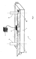
- a device 1 comprises at least one coil 2 generating magnetic field connected to at least one power generator 3 which is controlled by a control unit 4 secured to a vehicle (not shown).
- the device 1 comprises a box 5 mechanically welded or in composite.
- This box is formed for example of steel sheets. It is substantially parallelepipedic and includes a wall before 5a, two side walls 5b, 5c, a bottom 5d and a 5th rear wall on which legs 6 are welded allowing the fixing of the box to the vehicle. 5d background could be omitted.
- the walls are here shown transparent for facilitate the presentation of the invention.
- the power generator 3 is shown here attached to the rear wall 5th. It could of course be directly fixed on or inside the vehicle, outside the box 5.
- the coil 2 is fixed on a base 7 which carries a shaft 8 pivotally mounted relative to two integral bearings 9a, 9b respectively of the front walls 5a and rear 5e of the box 5.
- the bearings 9a and 9b are formed for example by ball bearings.
- the shaft 8 materializes an axis 10 with respect to which the coil 2 can be swiveled.
- Axis 10 is substantially perpendicular to the front walls 5a and rear 5e of the box as well as to axis 11 of coil 2.
- the coil 2 can be pivoted according to a angle at least equal to 90 °, which allows the coil of a folded position, in which its axis 11 is substantially horizontal, in a deployed position in which the axis 11 is substantially vertical.
- This pivoting is controlled by an actuator 12.
- the actuator is an electric motor which drives a chain or a belt 13 meshing on a grooved part of the shaft 8 or a gear (not shown).
- the actuator 12 is implemented from the housing of control 4 to which it is connected via a cable conductor 14 which is here connected to the power unit 3.
- Another conductive cable 15 connects the housing of power 3 to the coil 2 and a conductive cable 16 connects the power box 3 to the control box 4.
- a locking device 17 is fixed to the wall before 5a.
- This device 17 is formed for example by a electromagnet comprising a rod pushed by a spring. The rod enters an imprint carried by the shaft 8, thus ensuring the locking of the shaft and the coil by report to the box.
- At least two fingerprints will be provided on the tree 8, angularly spaced 90 ° apart, and arranged to allow the coil to be locked in two positions angular: the folded position and the deployed position.
- Locking will be performed automatically when passage of the coil in one or the other position.
- Unlocking will be controlled remotely from the control unit 4.
- the actuator will be connected to the control unit control 4 by a conductive cable not shown.
- Figure 1 shows the spool in its deployed position which is the one adopted to carry out an operation of demining.
- Figure 2 shows the coil 2 in its folded position in which it is housed inside the box 5. In this position the coil is masked by the box 5. It therefore does not interfere with the vehicle crew and in particular does not disturbs neither the visibility nor the movements of the turret or cannon.
- the coils are kept folded during the phases combat or displacement. Only when an area mined is spotted that the vehicle manager will command the swiveling of the demining coils to carry out a clearance of the area of land.
- Figures 3 and 4 show a second mode of realization of the invention.
- box 5 contains two coils 2a, 2b. Each coil can be rotated from the folded position shown in Figure 4 to adopt the deployed position shown in Figure 3.
- a single power unit 3 (controlled by the control 4) supplies the two coils 2a and 2b.
- Each coil 2a, 2b includes a device for specific locking 17a, 17b which is actuated from the control unit 4.
- Figure 5 shows a third embodiment of the invention. This mode differs from that of Figures 3 and 4 in that the box 5 carries a fixed coil 18 which surrounds the box and which is connected to a second generator power 19.
- This box contains the first circuits power generators specific to coils 2a and 2b and the second power generator circuit specific to the fixed coil 18.
- Such a fixed coil is described for example by the patent FR2701105.
- Such an embodiment allows depending on operational needs to give certain characteristics of the signal generated.
- Figure 6 shows an alternative embodiment of the device according to the invention.
- the box has a shield plate flakes 20 which is fixed to the front wall 5a of the box 5.
- This splinterproof plate is made of steel and it allows protect the coils and the generator during demining operations.
- the splinter-proof plate 20 is here shown fixed. She could of course be carried out in the form of a hinged cover to box 5, cover can be folded down to close the box when the coils are in their folded position. A suitable specific motorization (not shown) will then control the opening of the box and the positioning of the splinter guard 20. This motorization will be controlled by the control unit 4.
- Chip plates may also be attached on the side walls 5b and 5c of the box 5.
Landscapes
- Engineering & Computer Science (AREA)
- General Engineering & Computer Science (AREA)
- Automatic Cycles, And Cycles In General (AREA)
- Shielding Devices Or Components To Electric Or Magnetic Fields (AREA)
- Tents Or Canopies (AREA)
Abstract
Description
- les figures 1 et 2 sont des vues frontales en perspective d'un premier mode de réalisation de l'invention, la bobine étant représentée en position déployée sur la figure 1 et en position repliée sur la figure 2,
- les figures 3 et 4 sont des vues frontales en perspective d'un deuxième mode de réalisation de l'invention, les bobines étant représentées en positions déployées sur la figure 3 et en positions repliées sur la figure 4,
- La figure 5 représente un troisième mode de réalisation de l'invention,
- la figure 6 représente une variante de réalisation de l'invention.
Claims (9)
- Dispositif (1) de déminage de mines magnétiques, dispositif comprenant au moins une bobine (2) génératrice de champ magnétique reliée à au moins un générateur de puissance (3) qui est actionné par un boítier de commande (4), dispositif caractérisé en ce que la bobine (2) est montée pivotante par rapport à un caisson (5) et peut occuper au moins deux positions par rapport à celui-ci: une position repliée dans laquelle elle se loge à l'intérieur du caisson (5) et une position déployée dans laquelle elle sort du caisson.
- Dispositif selon la revendication 1, caractérisé en ce que la bobine (2) pivote d'un angle au moins égal à 90° pour passer de sa position repliée à sa position déployée.
- Dispositif selon une des revendications 1 ou 2, caractérisé en ce qu'il comporte au moins un actionneur (12) permettant de provoquer le pivotement de la bobine (2) et son passage de sa position repliée à sa position déployée.
- Dispositif selon une des revendications 1 à 3, caractérisé en ce qu'il comporte au moins un dispositif de verrouillage (17) actionnable à distance et assurant le verrouillage de la bobine (2) dans au moins une de ses positions.
- Dispositif selon une des revendications 1 à 4, caractérisé en ce qu'il comporte au moins deux bobines (2a,2b) montées pivotantes par rapport au caisson (5).
- Dispositif selon une des revendications 1 à 5, caractérisé en ce qu'il comporte au moins un bobinage fixe (18) entourant le caisson (5) et relié à un deuxième générateur de puissance (19).
- Dispositif selon une des revendications 1 à 6, caractérisé en ce que le caisson (5) comporte au moins une plaque pare éclats (20).
- Dispositif selon la revendication 7, caractérisé en ce que la plaque pare éclats (20) est montée pivotante par rapport au caisson (5).
- Dispositif selon une des revendications 1 à 8, caractérisé en ce que le caisson (5) porte au moins un générateur de puissance (3,19) destiné à alimenter la ou les bobines (2).
Applications Claiming Priority (2)
| Application Number | Priority Date | Filing Date | Title |
|---|---|---|---|
| FR0301506 | 2003-02-06 | ||
| FR0301506A FR2851037B1 (fr) | 2003-02-06 | 2003-02-06 | Dispositif de deminage repliable |
Publications (2)
| Publication Number | Publication Date |
|---|---|
| EP1445572A1 true EP1445572A1 (fr) | 2004-08-11 |
| EP1445572B1 EP1445572B1 (fr) | 2006-10-18 |
Family
ID=32606025
Family Applications (1)
| Application Number | Title | Priority Date | Filing Date |
|---|---|---|---|
| EP20040290209 Expired - Lifetime EP1445572B1 (fr) | 2003-02-06 | 2004-01-27 | Dispositif de déminage repliable |
Country Status (4)
| Country | Link |
|---|---|
| EP (1) | EP1445572B1 (fr) |
| DE (1) | DE602004002787T2 (fr) |
| FR (1) | FR2851037B1 (fr) |
| NO (1) | NO329673B1 (fr) |
Citations (6)
| Publication number | Priority date | Publication date | Assignee | Title |
|---|---|---|---|---|
| DE3444037A1 (de) * | 1984-12-03 | 1986-06-12 | Honeywell Gmbh, 6050 Offenbach | Raeumeinrichtung fuer minen mit magnetsensor |
| US4840105A (en) * | 1987-03-16 | 1989-06-20 | Israel Aircraft Industries Ltd. | Mine field clearing apparatus |
| DE4441075C1 (de) * | 1994-11-18 | 1996-05-02 | Walter Krohn | Minen-Räumfahrzeug |
| DE19540961A1 (de) * | 1995-10-21 | 1997-04-24 | Foerster Inst Dr Friedrich | Fahrbarer Sondenträger |
| FR2750204A1 (fr) * | 1996-06-19 | 1997-12-26 | Giat Ind Sa | Bobine de deminage et dispositif de deminage en faisant application |
| US5712441A (en) * | 1995-04-20 | 1998-01-27 | Firma Wegmann & Co. | Land-mine search-and-removal device mounted on a vehicle, especially a military tank, and method of locating and destroying such mines with such a device |
-
2003
- 2003-02-06 FR FR0301506A patent/FR2851037B1/fr not_active Expired - Fee Related
-
2004
- 2004-01-27 EP EP20040290209 patent/EP1445572B1/fr not_active Expired - Lifetime
- 2004-01-27 DE DE200460002787 patent/DE602004002787T2/de not_active Expired - Lifetime
- 2004-02-05 NO NO20040532A patent/NO329673B1/no not_active IP Right Cessation
Patent Citations (6)
| Publication number | Priority date | Publication date | Assignee | Title |
|---|---|---|---|---|
| DE3444037A1 (de) * | 1984-12-03 | 1986-06-12 | Honeywell Gmbh, 6050 Offenbach | Raeumeinrichtung fuer minen mit magnetsensor |
| US4840105A (en) * | 1987-03-16 | 1989-06-20 | Israel Aircraft Industries Ltd. | Mine field clearing apparatus |
| DE4441075C1 (de) * | 1994-11-18 | 1996-05-02 | Walter Krohn | Minen-Räumfahrzeug |
| US5712441A (en) * | 1995-04-20 | 1998-01-27 | Firma Wegmann & Co. | Land-mine search-and-removal device mounted on a vehicle, especially a military tank, and method of locating and destroying such mines with such a device |
| DE19540961A1 (de) * | 1995-10-21 | 1997-04-24 | Foerster Inst Dr Friedrich | Fahrbarer Sondenträger |
| FR2750204A1 (fr) * | 1996-06-19 | 1997-12-26 | Giat Ind Sa | Bobine de deminage et dispositif de deminage en faisant application |
Also Published As
| Publication number | Publication date |
|---|---|
| DE602004002787T2 (de) | 2007-08-23 |
| FR2851037B1 (fr) | 2005-03-18 |
| DE602004002787D1 (de) | 2006-11-30 |
| NO20040532L (no) | 2004-08-09 |
| EP1445572B1 (fr) | 2006-10-18 |
| NO329673B1 (no) | 2010-11-29 |
| FR2851037A1 (fr) | 2004-08-13 |
Similar Documents
| Publication | Publication Date | Title |
|---|---|---|
| EP3625624B1 (fr) | Dispositif de protection d'un capteur optique | |
| CA2312513C (fr) | Serrure de securite motorisee | |
| EP1617163B1 (fr) | Dispositif de tir de projectiles | |
| LU86219A1 (fr) | Poutre heliportee et rotative pour supporter des appareils de prise de vues photographiques convenant pour des releves stereophotogrammetriques industriels | |
| EP0411993A1 (fr) | Affût anti-aérien léger déployable | |
| FR2478809A1 (fr) | Mine antichar a grande surface d'action | |
| FR2917063A1 (fr) | Dispositif de fermeture d'un fuselage lie a un objet sous-marin remorque et engin ainsi equipe | |
| EP1448947B1 (fr) | Systeme d'observation et/ou de tir | |
| EP1445572B1 (fr) | Dispositif de déminage repliable | |
| CA2021945A1 (fr) | Affut anti-aerien leger deployable | |
| EP0034532B1 (fr) | Mine dispersable bidirectionnelle à charge formée | |
| CA2227886C (fr) | Bobine de deminage et dispositif de deminage en faisant application | |
| EP0236160B1 (fr) | Antenne radar à faible encombrement | |
| EP2040234B1 (fr) | Système de détection de tentative d'intrusion comprenant des moyens de détection de chocs et/ou de vibrations intégrés aux poteaux d'une clôture, et dispositif à monter sur des poteaux de clôture | |
| FR2911846A1 (fr) | Dispositif lance leurres pour aeronef | |
| FR2780774A1 (fr) | Dispositif d'autoprotection passive pour engin mobile tel qu'un helicoptere | |
| FR2990503A1 (fr) | Dispositif de montage d'une tourelle sur un vehicule blinde et vehicule equipe d'une tourelle fixee avec un tel dispositif de montage | |
| EP0942257B1 (fr) | Mine, notamment antichar ou antivehicule, comportant des moyens de confirmation de la presence d'une cible | |
| EP1837234B1 (fr) | Dispositif d'embarquement et de débarquement d'un module mobile d'un véhicule | |
| FR2589633A1 (fr) | Antenne de pointage du type actif | |
| EP1494310A1 (fr) | Mât optronique bi-antennaire | |
| WO2005078378A1 (fr) | Dispositif securise d'emport et de tir de cartouches telles que des cartouches de leurrage | |
| CA2931934C (fr) | Structure segmentee, en particulier pour reflecteur d'antenne de satellite, avec dispositif de deploiement a rotation et translation combinees | |
| FR2519784A1 (fr) | Dispositif de transmission multivoies d'un ordre pyrotechnique comportant un ensemble relais a relevement de pieces | |
| FR2924211A1 (fr) | Dispositif d'autoprotection d'un vehicule |
Legal Events
| Date | Code | Title | Description |
|---|---|---|---|
| PUAI | Public reference made under article 153(3) epc to a published international application that has entered the european phase |
Free format text: ORIGINAL CODE: 0009012 |
|
| AK | Designated contracting states |
Kind code of ref document: A1 Designated state(s): AT BE BG CH CY CZ DE DK EE ES FI FR GB GR HU IE IT LI LU MC NL PT RO SE SI SK TR |
|
| AX | Request for extension of the european patent |
Extension state: AL LT LV MK |
|
| 17P | Request for examination filed |
Effective date: 20041012 |
|
| AKX | Designation fees paid |
Designated state(s): DE GB IT |
|
| GRAP | Despatch of communication of intention to grant a patent |
Free format text: ORIGINAL CODE: EPIDOSNIGR1 |
|
| GRAS | Grant fee paid |
Free format text: ORIGINAL CODE: EPIDOSNIGR3 |
|
| GRAA | (expected) grant |
Free format text: ORIGINAL CODE: 0009210 |
|
| AK | Designated contracting states |
Kind code of ref document: B1 Designated state(s): DE GB IT |
|
| REG | Reference to a national code |
Ref country code: GB Ref legal event code: FG4D Free format text: NOT ENGLISH |
|
| REF | Corresponds to: |
Ref document number: 602004002787 Country of ref document: DE Date of ref document: 20061130 Kind code of ref document: P |
|
| GBT | Gb: translation of ep patent filed (gb section 77(6)(a)/1977) |
Effective date: 20061120 |
|
| PLBE | No opposition filed within time limit |
Free format text: ORIGINAL CODE: 0009261 |
|
| STAA | Information on the status of an ep patent application or granted ep patent |
Free format text: STATUS: NO OPPOSITION FILED WITHIN TIME LIMIT |
|
| 26N | No opposition filed |
Effective date: 20070719 |
|
| REG | Reference to a national code |
Ref country code: GB Ref legal event code: 732E Free format text: REGISTERED BETWEEN 20090625 AND 20090701 |
|
| PGFP | Annual fee paid to national office [announced via postgrant information from national office to epo] |
Ref country code: DE Payment date: 20191218 Year of fee payment: 17 Ref country code: IT Payment date: 20200102 Year of fee payment: 17 Ref country code: GB Payment date: 20191223 Year of fee payment: 17 |
|
| REG | Reference to a national code |
Ref country code: DE Ref legal event code: R119 Ref document number: 602004002787 Country of ref document: DE |
|
| GBPC | Gb: european patent ceased through non-payment of renewal fee |
Effective date: 20210127 |
|
| PG25 | Lapsed in a contracting state [announced via postgrant information from national office to epo] |
Ref country code: DE Free format text: LAPSE BECAUSE OF NON-PAYMENT OF DUE FEES Effective date: 20210803 Ref country code: GB Free format text: LAPSE BECAUSE OF NON-PAYMENT OF DUE FEES Effective date: 20210127 |
|
| PG25 | Lapsed in a contracting state [announced via postgrant information from national office to epo] |
Ref country code: IT Free format text: LAPSE BECAUSE OF NON-PAYMENT OF DUE FEES Effective date: 20210127 |