EP1445566A1 - Ring-Dichtungsanordnung für einen indirekt beheizten Drehrohrofen - Google Patents
Ring-Dichtungsanordnung für einen indirekt beheizten Drehrohrofen Download PDFInfo
- Publication number
- EP1445566A1 EP1445566A1 EP04001438A EP04001438A EP1445566A1 EP 1445566 A1 EP1445566 A1 EP 1445566A1 EP 04001438 A EP04001438 A EP 04001438A EP 04001438 A EP04001438 A EP 04001438A EP 1445566 A1 EP1445566 A1 EP 1445566A1
- Authority
- EP
- European Patent Office
- Prior art keywords
- ring
- segments
- sealing
- arrangement according
- sealing arrangement
- Prior art date
- Legal status (The legal status is an assumption and is not a legal conclusion. Google has not performed a legal analysis and makes no representation as to the accuracy of the status listed.)
- Granted
Links
- 238000007789 sealing Methods 0.000 title claims abstract description 67
- 238000010438 heat treatment Methods 0.000 claims abstract description 30
- 239000003566 sealing material Substances 0.000 claims abstract description 7
- 239000000463 material Substances 0.000 claims description 17
- 238000005299 abrasion Methods 0.000 claims description 7
- 229920000049 Carbon (fiber) Polymers 0.000 claims description 6
- 239000004917 carbon fiber Substances 0.000 claims description 6
- VNWKTOKETHGBQD-UHFFFAOYSA-N methane Chemical compound C VNWKTOKETHGBQD-UHFFFAOYSA-N 0.000 claims description 3
- 230000001590 oxidative effect Effects 0.000 claims description 3
- 230000000694 effects Effects 0.000 claims description 2
- 238000005498 polishing Methods 0.000 claims description 2
- OKTJSMMVPCPJKN-UHFFFAOYSA-N Carbon Chemical class [C] OKTJSMMVPCPJKN-UHFFFAOYSA-N 0.000 description 9
- 229910002804 graphite Inorganic materials 0.000 description 7
- 239000010439 graphite Substances 0.000 description 7
- 125000006850 spacer group Chemical group 0.000 description 7
- 239000011248 coating agent Substances 0.000 description 3
- 238000000576 coating method Methods 0.000 description 3
- 239000000835 fiber Substances 0.000 description 3
- 239000007789 gas Substances 0.000 description 3
- 229910001018 Cast iron Inorganic materials 0.000 description 2
- 239000012080 ambient air Substances 0.000 description 2
- 239000011230 binding agent Substances 0.000 description 2
- 210000003746 feather Anatomy 0.000 description 2
- 230000001771 impaired effect Effects 0.000 description 2
- 239000000203 mixture Substances 0.000 description 2
- 230000003746 surface roughness Effects 0.000 description 2
- UGFAIRIUMAVXCW-UHFFFAOYSA-N Carbon monoxide Chemical compound [O+]#[C-] UGFAIRIUMAVXCW-UHFFFAOYSA-N 0.000 description 1
- 239000000853 adhesive Substances 0.000 description 1
- 230000001070 adhesive effect Effects 0.000 description 1
- 239000003570 air Substances 0.000 description 1
- 229910052799 carbon Inorganic materials 0.000 description 1
- 238000005352 clarification Methods 0.000 description 1
- 238000005056 compaction Methods 0.000 description 1
- 230000007613 environmental effect Effects 0.000 description 1
- 239000003546 flue gas Substances 0.000 description 1
- 239000011888 foil Substances 0.000 description 1
- 238000000034 method Methods 0.000 description 1
- 230000003068 static effect Effects 0.000 description 1
- 239000000126 substance Substances 0.000 description 1
- 238000007669 thermal treatment Methods 0.000 description 1
Images

Classifications
-
- F—MECHANICAL ENGINEERING; LIGHTING; HEATING; WEAPONS; BLASTING
- F27—FURNACES; KILNS; OVENS; RETORTS
- F27B—FURNACES, KILNS, OVENS OR RETORTS IN GENERAL; OPEN SINTERING OR LIKE APPARATUS
- F27B7/00—Rotary-drum furnaces, i.e. horizontal or slightly inclined
- F27B7/20—Details, accessories or equipment specially adapted for rotary-drum furnaces
- F27B7/22—Rotary drums; Supports therefor
- F27B7/24—Seals between rotary and stationary parts
Definitions
- the invention relates to a ring seal arrangement for an indirectly heated Rotary tube furnace according to the preamble of claim 1.
- Indirectly heated rotary kilns contain a rotary tube, which is usually bowl-shaped is surrounded by a heating tunnel. Usually the rotary tube is not entirely surrounded by the tunnel, but protrudes from the front of the tunnel Tunnel out. Inside the heating tunnel, heated gas is passed through the heating tunnel led to the energy for the chemical run off in the rotary tube and / or to provide thermal processes.
- the heating tunnel also has this via one or more inlets and outlets for heating gas.
- the rotary tube must be sealed against the front of the heating tunnel, so that the heating medium does not flow from the front of the heating tunnel and / or Ambient air can flow into the heating tunnel.
- heating medium reduces the efficiency of the heating process within the heating tunnel, on the other hand, areas outside the tunnel become unnecessary and undesirably exposed to the sometimes considerable heat of the heating medium.
- Especially efficient sealing is important if flue gas or as the heating medium similar is used. An undesirable escape of the heating medium would then also mean an environmental impact. Likewise, an unwanted means Inflow of ambient air results in a loss of efficiency.
- Such rotary tube circumferential seals usually contain segments made of cast iron or carbite-carbon fiber mixture. These are usually about one with weights loaded cable feed pressed against the rotating drum. They have cast iron Segments the disadvantage that the abrasion is particularly high and at the joints of the Segments there is no qualified sealing. Segments made of carbite-carbon fiber mixture tend to break due to their brittleness, making them more common need to be replaced, which leads to idle times.
- the heating medium of the rotary kiln mostly consists of one, several hundred, often over 1000 ° C and there is also an oxidizing gas. It must be guaranteed that the material is sufficiently large even under these unfavorable conditions Stability.
- a ring seal for a rotary kiln is known as a fixed wreath is provided, which is formed from a series of graphite parts which are arranged in a partially overlapping abutting manner and are held with their inside against a cylindrical rotary tube surface, which is coaxial with the rotary kiln and rotates with it.
- the pressing is done by a rope loop tied at its ends that surrounds the graphite blocks.
- this rotary kiln described in this document is not an indirect one heated rotary tube, so that the ring seal far lower temperatures and temperature differences is exposed.
- the contact pressure must also be due here of the material (graphite) are in the order of magnitude described above.
- the invention is based on the basic idea that in a ring seal for an indirectly heated rotary kiln between a heating tunnel and a rotary tube, in which several overlapping segments are present, which are pressed radially against the rotary drum by pressing means, the segments essentially consist of a heat-resistant lightweight sealing material.
- Felts in particular made of carbon fibers, are particularly preferred.
- a felt material in the sense of the invention is understood to mean that material fibers of the same or different, not too short length form a material pact with more or less great irregularity, which generally has a certain porosity, but is nevertheless sufficiently compact. Internal cavities and channels are preferably avoided.
- Such a material is preferably dimensionally stable and, particularly preferably, consists of graphite fibers and a carbon binder.
- the properties of the starting fibers as well as their length and the type of binder as well as the degree of compaction and any thermal treatment can be specified within certain limits. It is further particularly preferred if this material is coked and graphitized. It can be used in extreme cases up to temperatures of 3000 ° C and is known in the form of self-supporting plates, cylinders and other components, among others under the brand name SIGRATHERM® as graphite adhesive felt.
- a typical material density is usually less than 1 g / cm 3 . Bulk densities of 0,1 0.16 g / cm 3 are particularly preferred.
- a "lightweight sealing material” is understood to mean a sealing material whose density is ⁇ 1.5 g / cm 3 .
- the pressure means preferably have a closed ring, which the segments on their side facing away from the rotary tube are radially elastically encased.
- the pressing means include several together, connected in particular by springs or other elastic tensioning means Belt sections that form a tension ring.
- a band-shaped clamping ring distributes the anyway only small contact pressures required on an advantageously large area.
- Press-on means of the aforementioned type, in particular according to one of claims 5 to 8 are of independent inventive importance, i.e. also independent of the license plate of claim 1. The same applies to the feature of claim 9.
- the contact pressure required is greater than that State of the art much lower. In some embodiments, it is only 30 to 50 kN still. In the presence of a clamping ring described above, the contact pressure must also be calculated precisely, since the segments - unlike cable loops with weights or the like at their ends - with less static friction be pressed evenly radially onto the rotary tube.
- the lightweight sealing material no longer exerts any abrasion forces on the rotary tube.
- the segments of the seal consist of material which has a polishing effect on the rotary tube.
- the surface roughness of the sealing surface of the rotary tube is reduced, which the seal improves and thus the tightness is further strengthened. Due to the the lower surface roughness of the rotary tube also reduces the abrasion of the seal, which further increases the life and sealing properties of the seal or improved.
- a carbon fiber felt is also suitable for this purpose.
- an inventive ring sealing arrangement includes 1 a ring of sealing segments 10, which the rotary tube 20 radially surrounds an indirectly heated rotary kiln.
- the sealing segments 10 consist of a lightweight sealing material, which prefers heat resistance of more, especially significantly more than 280 ° C, e.g. > 1000 ° C.
- the sealing segments 10 preferably consist of a material which is heat-resistant even in an oxidizing atmosphere. This results in the choice of the heating medium for the rotary kiln, more options.
- a suitable one Material is high-temperature carbon fiber felt, as described at the beginning.
- a graphite hard felt was used, which the side surface facing the heating tunnel additionally with a graphite foil ⁇ 0.5 mm was coated (coating 10 C).
- a coating of the sealing surfaces 14 C. and / or 14 D with sliding conveyors such as graphite paste also increases the density.
- a sealing segment 10 has two overlapping projections 12.
- the facing ones overlap Overlap projections 12, 12 A, or 12, 12 B, adjacent sealing segments 10, 10 A, or 10, 10 B, flat and form contact areas 14 A or 14 B.
- Overlapped one sealing segment the neighboring segments once on the tunnel side and once tunnel away.
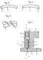
- These overlap projections can - as can be seen in FIG. 3 - be rectangular segment segments.
- FIG. 4 there are other embodiments conceivable, such as in Fig. 4, where a sealing segment with a stepped Overlap projection 12 is shown.
- a sealing element can also Include graded overlap protrusions.
- 5 shows a partial perspective illustration of the overlap two sealing elements - here the elements from FIG. 4.
- a wreath of 8 sealing segments is shown.
- the number of seal segments can vary depending on the requirements and size of the rotary kiln. there however, the number of sealing segments should be kept as low as possible. Most of time the number of sealing segments will be approximately between 6 and 12.
- the sealing segments 10 have at least at Commissioning the seal - an identical shape. This ensures a uniform Sealing of the rotary tube 20.
- the seal there are also embodiments of the seal conceivable, in which at least not all sealing segments are identical, e.g. by doing alternate larger and smaller segments or otherwise vary the segments.
- the sealing segments 10 are of one or a plurality of pressing means 30 surround the sealing segments 10 radially to the Press on rotary tube 20.
- the pressing means 30 are preferably in the form of a closed ring designed, which the segments on the side facing away from the rotary tube radially elastic spans.
- the ring - as shown in Fig. 1 - consists of several flat strip-shaped sections 32 which are connected to one another, in particular by springs 34, are connected and thus form a clamping ring. This ensures an even one radial contact pressure over the entire circumference of the rotary tube. Instead of feathers other elastic clamping devices can also be used.
- pressing means can be used that have a radial pressing ensure the sealing segments on the rotary tube.
- Pressure means would be e.g. a flat band completely enveloping the sealing segment ring with overlapping ends, which in turn - e.g. via cables - is kept under tension.
- the sealing segments can also these spanning traction cables are pressed radially onto the seal itself.
- the pressing means can rest on the one hand on the sealing segments, as shown in Fig. 6 to see.
- a suitable recess in the sealing segments 10 can also be present, which receives the or the pressure means.
- a suitable width of the sealing segment there may also be several cutouts.
- the sealing segments are usually covered and / or guided covered on its side facing away from the rotary tube.
- This cover and / or leadership preferably has slots or recesses through which the abrasion of the seal is self-removing from the seal, e.g. by just falling out. This prevents that the abrasion settles between the overlapping projections and their mobility impaired or even blocked the sealing segments. If a big one Part of the side of the sealing segments facing away from the rotary tube by the pressing means covered, these preferably also contain guides and / or slots.
- Fig. 6 shows - a section and not to scale - a longitudinal section through a Embodiment of an indirectly heatable rotary kiln with installed seal.
- a heating tunnel 40 On a heating tunnel 40 has a first retaining ring 42 arranged on the end face is separated from a second retaining ring 44 by a spacer 46.
- the two The retaining rings are at a somewhat radial distance from the rotary tube 20.
- the spacer 46 is arranged remote from the rotary tube such that between the rotary tube 20 and the spacer 46 enough space for the sealing segments 10 and the pressing means 30 available is. If the spacer - as shown in Fig.
- the sealing segments 10 is slightly wider than that Sealing segments 10, the sealing segments 10 by means of one or more Pressing elements pressed onto the retaining rings 42 on the heating tunnel side. This can e.g. via one or more adjusting screws 48 arranged in the retaining ring 44.
- all other pressure systems are also conceivable that have a sealing Allow the seal to rest against an end face.
- the width of the spacer 46 be dimensioned exactly so that it is the width of the sealing segments equivalent. If the sealing segment material is compressible, the width of the Seal in operation can also be determined by the width of the spacer 46 by the sealing segments are pressed between the retaining rings. It can also the retaining ring 42 may be part of the heating tunnel 40.
- the sealing segments 10 must in any case bear against the heating tunnel 40 in such a way that there is something inside it Heating medium, which the sealing segments 10 along the axis of the rotary tube in Flows in the direction of arrow B, do not flow around the side and so into the environment 52 can reach.
Landscapes
- Engineering & Computer Science (AREA)
- Mechanical Engineering (AREA)
- General Engineering & Computer Science (AREA)
- Muffle Furnaces And Rotary Kilns (AREA)
- Furnace Details (AREA)
Abstract
Description
- Fig. 1
- eine Dichtungsanordnung in (achsialer) Seitenansicht - Schnitt entlang der Linie IV-IV gemäß Fig. 6 - schematisch und ohne Abdeckung);
- Fig. 2
- von derselben Dichtungsanordnung ein erfindungsgemäßes Dichtungssegment in radialer Außenansicht (Ansicht A-A) gemäß Fig. 1 in Überlappung beidseitig benachbarten Dichtungssegmenten;
- Fig.3
- dasselbe Dichtungssegment in Stirnseitenansicht analog Fig. 1;
- Fig. 4
- eine alternative Ausführungsform eines erfindungsgemäßen Dichtungssegments in derselben Ansicht wie Fig. 3;
- Fig. 5
- eine perspektivische Explosionsansicht zweier Dichtungselemente aus Fig. 4 - ausschnittsweise; sowie
- Fig. 6
- einen Drehrohrofen mit einer erfindungsgemäßen Dichtung in Achsial-Schnittansicht - schematisch und ausschnittsweise.
- 1
- Ring-Dichtungsanordnung
- 10
- Dichtungssegment
- 10 A
- Dichtungssegment
- 10 B
- Dichtungssegment
- 10 C
- Beschichtung
- 12
- Überlappungsvorsprung
- 12 A
- Dichtungssegment
- 12 B
- Überlappungsvorsprung
- 14 A
- Kontaktfläche
- 14 B
- Kontaktfläche
- 14 C
- Dichtflächen
- 14 D
- Dichtflächen
- 20
- Drehrohr
- 30
- Anpreßmittel
- 32
- flachbandförmige Abschnitte
- 34
- Feder
- 36
- Zugseil
- 40
- Beheizungstunnel
- 42
- erster Haltering
- 44
- zweiter Haltering
- 46
- Abstandshalter
- 48
- Stellschraube
- 50
- Innenraum
- 52
- Umgebung
- d
- Abstand
Claims (9)
- Ring-Dichtungsanordnung für einen indirekt beheizten Drehrohrofen zwischen einem Beheizungstunnel und einem Drehrohr (20) mit mehreren sich überlappenden, einen Dichtungsring bildenden Segmenten (10), die durch Anpreßmittel (30) radial an das Drehrohr (20) angepreßt werden,
dadurch gekennzeichnet, daß die Segmente (10) im wesentlichen aus einem hitzebeständigen Leichtbau-Dichtungsmaterial bestehen. - Ring-Dichtungsanordnung nach Anspruch 1, dadurch gekennzeichnet, daß das Segmentmaterial eine Temperaturstandfestigkeit von größer als 280° C aufweist.
- Ring-Dichtungsanordnung nach Anspruch 1 oder 2, gekennzeichnet durch eine Temperaturstandfestigkeit des Segmentmaterials von größer als 280° C in oxidierender Atmosphäre.
- Ring-Dichtungsanordnung nach einem der Ansprüche 1 bis 3, dadurch gekennzeichnet, daß die Segmente im wesentlichen aus hochtemperaturbeständigem Filz, vorzugsweise aus Carbonfaser, bestehen.
- Ring-Dichtungsanordnung nach einem der Ansprüche 1 bis 4, dadurch gekennzeichnet, daß die Anpreßmittel (30) als geschlossener Ring ausgestaltet ist, welcher die Segmente auf deren drehrohrabgewandter Seite radial elastisch umspannt.
- Ring-Dichtungsanordnung nach Anspruch 5, dadurch gekennzeichnet, daß der Ring aus mehreren flachbandförmigen Abschnitten (32) besteht, welche miteinander, insbesondere durch Federn (34), verbunden sind und einen Spannring bilden.
- Ring-Dichtungsanordnung nach einem der Ansprüche 1 bis 6, dadurch gekennzeichnet, daß die Segmente (10) aus einem Material bestehen, welches eine polierende Wirkung auf die Dichtfläche des Drehrohrs ausübt.
- Ring-Dichtungsanordnung nach einem der Ansprüche 1 bis 7, dadurch gekennzeichnet, daß der Anpreßkraft der Dichtung weniger als 300 kN ist.
- Ring-Dichtungsanordnung nach einem der Ansprüche 1 bis 8, dadurch gekennzeichnet, daß eine Abdeckung oder Führung des Dichtungsrings Schlitze und/oder Aussparungen derart aufweist, daß Abrieb von der Dichtung selbstentfernend ist.
Applications Claiming Priority (2)
| Application Number | Priority Date | Filing Date | Title |
|---|---|---|---|
| DE20302000U DE20302000U1 (de) | 2003-02-08 | 2003-02-08 | Ring-Dichtungsanordnung für einen indirekt beheizten Drehrohrofen |
| DE20302000U | 2003-02-08 |
Publications (2)
| Publication Number | Publication Date |
|---|---|
| EP1445566A1 true EP1445566A1 (de) | 2004-08-11 |
| EP1445566B1 EP1445566B1 (de) | 2012-08-08 |
Family
ID=32603282
Family Applications (1)
| Application Number | Title | Priority Date | Filing Date |
|---|---|---|---|
| EP04001438A Expired - Lifetime EP1445566B1 (de) | 2003-02-08 | 2004-01-23 | Ring-Dichtungsanordnung für einen indirekt beheizten Drehrohrofen |
Country Status (4)
| Country | Link |
|---|---|
| US (1) | US20040187750A1 (de) |
| EP (1) | EP1445566B1 (de) |
| CA (1) | CA2456230C (de) |
| DE (1) | DE20302000U1 (de) |
Cited By (3)
| Publication number | Priority date | Publication date | Assignee | Title |
|---|---|---|---|---|
| WO2017134309A1 (en) * | 2016-02-05 | 2017-08-10 | Royal Duyvis Wiener B.V. | Apparatus for drying and/or roasting beans or nibs |
| DE102024121397B3 (de) * | 2024-07-26 | 2025-09-25 | Eagleburgmann Germany Gmbh & Co. Kg | Dichtsystem zur Abdichtung zwischen einem rotierenden Bauteil und einem stationären Bauteil |
| DE102024121403A1 (de) * | 2024-07-26 | 2026-01-29 | Eagleburgmann Germany Gmbh & Co. Kg | Dichtsystem zur Abdichtung zwischen einem rotierenden Bauteil und einem stationären Bauteil |
Families Citing this family (8)
| Publication number | Priority date | Publication date | Assignee | Title |
|---|---|---|---|---|
| DE102015211538A1 (de) * | 2015-06-23 | 2016-12-29 | Trumpf Laser- Und Systemtechnik Gmbh | Bauzylinder-Anordnung für eine Maschine zur schichtweisen Fertigung dreidimensionaler Objekte |
| DE102018133566A1 (de) | 2018-12-21 | 2020-06-25 | Eisenmann Se | Drehrohrofen |
| CN109990096A (zh) * | 2019-05-13 | 2019-07-09 | 江苏海建股份有限公司 | 一种重力张紧石墨密封装置 |
| SE545368C2 (en) | 2021-02-26 | 2023-07-18 | Camfil Ab | Heat resistant regenerable air filter assembly |
| DE102022109305B4 (de) | 2022-04-14 | 2024-04-25 | Eagleburgmann Germany Gmbh & Co. Kg | Dichtungsanordnung eines Drehrohrofens |
| DE102023125383A1 (de) * | 2023-09-19 | 2025-03-20 | Eagleburgmann Germany Gmbh & Co. Kg | Drehrohrofendichtsystem |
| CN119394006B (zh) * | 2024-12-31 | 2025-03-18 | 宜宾市南溪区国科中农生物科技有限公司 | 一种酒糟饲料生产系统用的回转窑 |
| JP7759517B1 (ja) * | 2025-02-18 | 2025-10-23 | ノリタケ株式会社 | シール装置およびロータリーキルン |
Citations (4)
| Publication number | Priority date | Publication date | Assignee | Title |
|---|---|---|---|---|
| DE1750881A1 (de) * | 1967-06-16 | 1972-04-06 | Creusot Forges Ateliers | Dichtung fuer einen sich drehenden Behaelter |
| DE3047404A1 (de) * | 1979-12-24 | 1981-10-08 | Lafarge Conseils et Etudes, 75782 Paris | "vorrichtung zum abdichten eines drehofens" |
| EP1079191A1 (de) * | 1999-08-25 | 2001-02-28 | Franz Ragailler | Drehofen |
| JP2001133157A (ja) * | 1999-10-29 | 2001-05-18 | Meidensha Corp | 被処理物の加熱処理装置 |
Family Cites Families (12)
| Publication number | Priority date | Publication date | Assignee | Title |
|---|---|---|---|---|
| US4209175A (en) * | 1979-02-09 | 1980-06-24 | Allis-Chalmers Corporation | Articulated seal for rotating cylinder such as kiln or the like |
| CA1130335A (en) * | 1979-02-09 | 1982-08-24 | Robert M. Bliemeister | Seal for rotating cylinder such as kilns and the like |
| US4502702A (en) * | 1984-06-08 | 1985-03-05 | Nixon Robert J Jr | Segmented seal for rotary equipment |
| US5263724A (en) * | 1989-11-02 | 1993-11-23 | Volund Miljoteknik A/S | Segmented seal for rotary equipment |
| AT398129B (de) * | 1991-01-14 | 1994-09-26 | Waagner Biro Ag | Drehrohrwärmebehandlungsanlage, insbesondere drehrohrofen |
| DE4303298C1 (de) * | 1993-02-05 | 1994-02-10 | Gutehoffnungshuette Man | Sperrmediumdichtung für Drehrohröfen |
| DE19542563A1 (de) * | 1995-11-15 | 1997-05-22 | Flender A F & Co | Vorrichtung zur Abdichtung einer Schutzhaube eines Mühlenkörpers |
| DE19734381A1 (de) * | 1997-08-08 | 1999-02-11 | Hauni Maschinenbau Ag | Dichtungsanordnung |
| US6042370A (en) * | 1999-08-20 | 2000-03-28 | Haper International Corp. | Graphite rotary tube furnace |
| JP3550339B2 (ja) * | 2000-03-31 | 2004-08-04 | 株式会社栗本鐵工所 | 外熱式ロータリキルン |
| US6585271B2 (en) * | 2001-07-31 | 2003-07-01 | Halliburton Energy Services, Inc. | Seal member, assembly, and method |
| DE10201503A1 (de) * | 2002-01-17 | 2003-10-30 | Veba Oel Technologie & Automatisierung Gmbh | Drehrohrofen mit ringförmig geschlossener Stirnenddichtung, ringförmig geschlossene Dichtung für einen Drehrohrofen sowie Verfahren zum Herstellen einer solchen Dichtung |
-
2003
- 2003-02-08 DE DE20302000U patent/DE20302000U1/de not_active Expired - Lifetime
-
2004
- 2004-01-23 EP EP04001438A patent/EP1445566B1/de not_active Expired - Lifetime
- 2004-01-26 CA CA2456230A patent/CA2456230C/en not_active Expired - Fee Related
- 2004-02-06 US US10/773,977 patent/US20040187750A1/en not_active Abandoned
Patent Citations (4)
| Publication number | Priority date | Publication date | Assignee | Title |
|---|---|---|---|---|
| DE1750881A1 (de) * | 1967-06-16 | 1972-04-06 | Creusot Forges Ateliers | Dichtung fuer einen sich drehenden Behaelter |
| DE3047404A1 (de) * | 1979-12-24 | 1981-10-08 | Lafarge Conseils et Etudes, 75782 Paris | "vorrichtung zum abdichten eines drehofens" |
| EP1079191A1 (de) * | 1999-08-25 | 2001-02-28 | Franz Ragailler | Drehofen |
| JP2001133157A (ja) * | 1999-10-29 | 2001-05-18 | Meidensha Corp | 被処理物の加熱処理装置 |
Non-Patent Citations (1)
| Title |
|---|
| DATABASE WPI Section Ch Week 200156, Derwent World Patents Index; Class M24, AN 2001-505472, XP002279082 * |
Cited By (4)
| Publication number | Priority date | Publication date | Assignee | Title |
|---|---|---|---|---|
| WO2017134309A1 (en) * | 2016-02-05 | 2017-08-10 | Royal Duyvis Wiener B.V. | Apparatus for drying and/or roasting beans or nibs |
| US11039638B2 (en) | 2016-02-05 | 2021-06-22 | Royal Duyvis Wiener B.V. | Apparatus for drying and/or roasting beans or nibs |
| DE102024121397B3 (de) * | 2024-07-26 | 2025-09-25 | Eagleburgmann Germany Gmbh & Co. Kg | Dichtsystem zur Abdichtung zwischen einem rotierenden Bauteil und einem stationären Bauteil |
| DE102024121403A1 (de) * | 2024-07-26 | 2026-01-29 | Eagleburgmann Germany Gmbh & Co. Kg | Dichtsystem zur Abdichtung zwischen einem rotierenden Bauteil und einem stationären Bauteil |
Also Published As
| Publication number | Publication date |
|---|---|
| CA2456230C (en) | 2011-09-20 |
| DE20302000U1 (de) | 2004-07-08 |
| EP1445566B1 (de) | 2012-08-08 |
| CA2456230A1 (en) | 2004-08-08 |
| US20040187750A1 (en) | 2004-09-30 |
Similar Documents
| Publication | Publication Date | Title |
|---|---|---|
| DE3872128T2 (de) | Ventilspindelstopfbuechse fuer hohe druecke und temperaturen. | |
| AT412327B (de) | Strangführungsrolle | |
| EP1146263B1 (de) | Dichtring-Packung | |
| EP1445566B1 (de) | Ring-Dichtungsanordnung für einen indirekt beheizten Drehrohrofen | |
| DE3534478C2 (de) | Doppelbandpresse zum kontinuierlichen Verpressen von Werkstoffbahnen bei erhöhten Temperaturen | |
| DE102012106527A1 (de) | Walzenpresse mit gekühlter Bandage | |
| CH709168A2 (de) | Dichtungseinrichtung zur Bereitstellung einer Abdichtung zwischen benachbarten Komponenten und Turbomaschine mit einer solchen Dichtungseinrichtung. | |
| DE2436098A1 (de) | Drehmomentuebertragungsvorrichtung in scheibenbauweise | |
| DE3114695A1 (de) | Vorrichtung zur abdichtung des spaltes zwischen drehrohrofen und einlaufgehaeuse | |
| DE3700888A1 (de) | Gleitringabdichtung | |
| DE202018002101U1 (de) | Reiblamelle | |
| DE102015221168A1 (de) | Verfahren und Fertigungsvorrichtung zur Herstellung eines Doppelzahnriemens | |
| DE2934851C2 (de) | Verfahren zum Einführen eines Kabels in eine Vulkanisationskammer und Einrichtung zur Durchführung des Verfahrens | |
| DE1027024B (de) | Einrichtung zur Abdichtung bewegter Teile, insbesondere an Drehrohren | |
| DE2705879C2 (de) | ||
| WO2003029534A1 (de) | Spinndüse | |
| EP2856498B1 (de) | Suszeptor | |
| DE3017962C2 (de) | Walzenpresse zum Kompaktieren und Brikettieren von Schüttgütern | |
| DE3346220A1 (de) | Reibungskupplung | |
| DE2443989A1 (de) | Rotations-vorwaermwaermetauscher | |
| DE9212923U1 (de) | Gleitringdichtungsanordnung | |
| DE2536759C3 (de) | Dichtkolben für Betätigungszylinder | |
| EP4047254B1 (de) | Flanschverbindung, flanschdichtung und verfahren zum installieren einer neuen flanschdichtung | |
| DE3347359C2 (de) | Druckmittelbetätigte Zylinderreibungsbremse oder -kupplung | |
| DE2707781A1 (de) | Vorwaermer fuer den aeusseren heizkreis eines stirling-motors |
Legal Events
| Date | Code | Title | Description |
|---|---|---|---|
| PUAI | Public reference made under article 153(3) epc to a published international application that has entered the european phase |
Free format text: ORIGINAL CODE: 0009012 |
|
| AK | Designated contracting states |
Kind code of ref document: A1 Designated state(s): AT BE BG CH CY CZ DE DK EE ES FI FR GB GR HU IE IT LI LU MC NL PT RO SE SI SK TR |
|
| AX | Request for extension of the european patent |
Extension state: AL LT LV MK |
|
| 17P | Request for examination filed |
Effective date: 20041218 |
|
| AKX | Designation fees paid |
Designated state(s): AT DE FR GB IT |
|
| 17Q | First examination report despatched |
Effective date: 20071018 |
|
| RAP1 | Party data changed (applicant data changed or rights of an application transferred) |
Owner name: BP EUROPA SE |
|
| GRAC | Information related to communication of intention to grant a patent modified |
Free format text: ORIGINAL CODE: EPIDOSCIGR1 |
|
| GRAP | Despatch of communication of intention to grant a patent |
Free format text: ORIGINAL CODE: EPIDOSNIGR1 |
|
| GRAS | Grant fee paid |
Free format text: ORIGINAL CODE: EPIDOSNIGR3 |
|
| GRAA | (expected) grant |
Free format text: ORIGINAL CODE: 0009210 |
|
| AK | Designated contracting states |
Kind code of ref document: B1 Designated state(s): AT DE FR GB IT |
|
| REG | Reference to a national code |
Ref country code: GB Ref legal event code: FG4D Free format text: NOT ENGLISH |
|
| REG | Reference to a national code |
Ref country code: AT Ref legal event code: REF Ref document number: 569990 Country of ref document: AT Kind code of ref document: T Effective date: 20120815 |
|
| REG | Reference to a national code |
Ref country code: DE Ref legal event code: R082 Ref document number: 502004013666 Country of ref document: DE Representative=s name: MANN, BJOERN, DE Ref country code: DE Ref legal event code: R082 Ref document number: 502004013666 Country of ref document: DE Representative=s name: BJOERN MANN, DE |
|
| REG | Reference to a national code |
Ref country code: DE Ref legal event code: R096 Ref document number: 502004013666 Country of ref document: DE Effective date: 20121011 |
|
| PLBE | No opposition filed within time limit |
Free format text: ORIGINAL CODE: 0009261 |
|
| STAA | Information on the status of an ep patent application or granted ep patent |
Free format text: STATUS: NO OPPOSITION FILED WITHIN TIME LIMIT |
|
| 26N | No opposition filed |
Effective date: 20130510 |
|
| REG | Reference to a national code |
Ref country code: FR Ref legal event code: CA Effective date: 20130729 |
|
| REG | Reference to a national code |
Ref country code: DE Ref legal event code: R097 Ref document number: 502004013666 Country of ref document: DE Effective date: 20130510 |
|
| REG | Reference to a national code |
Ref country code: FR Ref legal event code: PLFP Year of fee payment: 13 |
|
| REG | Reference to a national code |
Ref country code: FR Ref legal event code: PLFP Year of fee payment: 14 |
|
| PGFP | Annual fee paid to national office [announced via postgrant information from national office to epo] |
Ref country code: FR Payment date: 20170126 Year of fee payment: 14 Ref country code: DE Payment date: 20161031 Year of fee payment: 14 |
|
| PGFP | Annual fee paid to national office [announced via postgrant information from national office to epo] |
Ref country code: AT Payment date: 20170109 Year of fee payment: 14 Ref country code: GB Payment date: 20170118 Year of fee payment: 14 |
|
| PGFP | Annual fee paid to national office [announced via postgrant information from national office to epo] |
Ref country code: IT Payment date: 20170127 Year of fee payment: 14 |
|
| REG | Reference to a national code |
Ref country code: DE Ref legal event code: R119 Ref document number: 502004013666 Country of ref document: DE |
|
| REG | Reference to a national code |
Ref country code: AT Ref legal event code: MM01 Ref document number: 569990 Country of ref document: AT Kind code of ref document: T Effective date: 20180123 |
|
| GBPC | Gb: european patent ceased through non-payment of renewal fee |
Effective date: 20180123 |
|
| PG25 | Lapsed in a contracting state [announced via postgrant information from national office to epo] |
Ref country code: DE Free format text: LAPSE BECAUSE OF NON-PAYMENT OF DUE FEES Effective date: 20180801 Ref country code: FR Free format text: LAPSE BECAUSE OF NON-PAYMENT OF DUE FEES Effective date: 20180131 |
|
| REG | Reference to a national code |
Ref country code: FR Ref legal event code: ST Effective date: 20180928 |
|
| PG25 | Lapsed in a contracting state [announced via postgrant information from national office to epo] |
Ref country code: AT Free format text: LAPSE BECAUSE OF NON-PAYMENT OF DUE FEES Effective date: 20180123 Ref country code: GB Free format text: LAPSE BECAUSE OF NON-PAYMENT OF DUE FEES Effective date: 20180123 |
|
| PG25 | Lapsed in a contracting state [announced via postgrant information from national office to epo] |
Ref country code: IT Free format text: LAPSE BECAUSE OF NON-PAYMENT OF DUE FEES Effective date: 20180123 |