EP1444932A1 - Linear extraction unit for the preparation under pressure of a drink from a cartridge - Google Patents
Linear extraction unit for the preparation under pressure of a drink from a cartridge Download PDFInfo
- Publication number
- EP1444932A1 EP1444932A1 EP03002817A EP03002817A EP1444932A1 EP 1444932 A1 EP1444932 A1 EP 1444932A1 EP 03002817 A EP03002817 A EP 03002817A EP 03002817 A EP03002817 A EP 03002817A EP 1444932 A1 EP1444932 A1 EP 1444932A1
- Authority
- EP
- European Patent Office
- Prior art keywords
- capsule
- extraction
- sub
- assembly
- module according
- Prior art date
- Legal status (The legal status is an assumption and is not a legal conclusion. Google has not performed a legal analysis and makes no representation as to the accuracy of the status listed.)
- Granted
Links
Images


Classifications
-
- A—HUMAN NECESSITIES
- A47—FURNITURE; DOMESTIC ARTICLES OR APPLIANCES; COFFEE MILLS; SPICE MILLS; SUCTION CLEANERS IN GENERAL
- A47J—KITCHEN EQUIPMENT; COFFEE MILLS; SPICE MILLS; APPARATUS FOR MAKING BEVERAGES
- A47J31/00—Apparatus for making beverages
- A47J31/24—Coffee-making apparatus in which hot water is passed through the filter under pressure, i.e. in which the coffee grounds are extracted under pressure
- A47J31/34—Coffee-making apparatus in which hot water is passed through the filter under pressure, i.e. in which the coffee grounds are extracted under pressure with hot water under liquid pressure
- A47J31/36—Coffee-making apparatus in which hot water is passed through the filter under pressure, i.e. in which the coffee grounds are extracted under pressure with hot water under liquid pressure with mechanical pressure-producing means
- A47J31/3604—Coffee-making apparatus in which hot water is passed through the filter under pressure, i.e. in which the coffee grounds are extracted under pressure with hot water under liquid pressure with mechanical pressure-producing means with a mechanism arranged to move the brewing chamber between loading, infusing and ejecting stations
- A47J31/3623—Cartridges being employed
- A47J31/3638—Means to eject the cartridge after brewing
-
- A—HUMAN NECESSITIES
- A47—FURNITURE; DOMESTIC ARTICLES OR APPLIANCES; COFFEE MILLS; SPICE MILLS; SUCTION CLEANERS IN GENERAL
- A47J—KITCHEN EQUIPMENT; COFFEE MILLS; SPICE MILLS; APPARATUS FOR MAKING BEVERAGES
- A47J31/00—Apparatus for making beverages
- A47J31/24—Coffee-making apparatus in which hot water is passed through the filter under pressure, i.e. in which the coffee grounds are extracted under pressure
- A47J31/34—Coffee-making apparatus in which hot water is passed through the filter under pressure, i.e. in which the coffee grounds are extracted under pressure with hot water under liquid pressure
- A47J31/36—Coffee-making apparatus in which hot water is passed through the filter under pressure, i.e. in which the coffee grounds are extracted under pressure with hot water under liquid pressure with mechanical pressure-producing means
- A47J31/3604—Coffee-making apparatus in which hot water is passed through the filter under pressure, i.e. in which the coffee grounds are extracted under pressure with hot water under liquid pressure with mechanical pressure-producing means with a mechanism arranged to move the brewing chamber between loading, infusing and ejecting stations
- A47J31/3623—Cartridges being employed
- A47J31/3633—Means to perform transfer from a loading position to an infusing position
Definitions
- the invention relates to the field of the preparation of beverages using the principle of extraction of a substance contained in an element of refill, commonly called "capsule", by crossing a stream of water under pressure.
- the invention relates more particularly to a module extraction system intended to equip a beverage preparation machine such than a coffee machine.
- the principle of extracting a capsule generally consists of (i) enclose the capsule in a pressure-resistant chamber, (ii) pierce one of the faces of the capsule, (iii) introduce a quantity of hot water into the capsule so as to create a closed environment under pressure to produce the liquid extract of coffee or the like, (iv) release the liquid extract through the opposite side of the capsule and, (v) collect the extract in a container of suitable capacity such as a cup.
- patent application EP 1090574 A1 it is a device extraction comprising a pair of jaws with a jaw portion fixed and a movable jaw part the latter being mounted so articulated and offset on the fixed part and a closing lever mechanism with several branches is associated to close the mobile part on the part fixed.
- Patent application WO 95/17121 relates to a device comprising a group formed by a fixed piston and a movable cylindrical body, the group being placed opposite a boiler.
- the boiler on the one hand, the fixed piston and the cylindrical body on the other hand, are separated by a zone where are positioned the receiving means, holding position and ejection of packaging.
- the means of support and the means of reception are different means; the former not being entirely retractable and being placed directly between the boiler and the body cylindrical to maintain the lateral edges of the packaging, the second being retractable and placed on one side of the cylindrical body for simply stop conditioning against the forces of gravity.
- Such a device is complex because it involves different pieces to both retain and correctly center the capsule (or packaging) in place in the extraction chamber.
- Patent application WO 98/47418 relates to a method of transformation of an express coffee machine, which works in extraction vertical with pre-dosed pellets used in a horizontal plane in one express coffee machine which works in horizontal extraction with pre-dosed tablets usable in a vertical plane.
- the machine is equipped with receiving and ejecting means consisting of a single retractable element movable below the extraction member by means electromechanical maneuver separate from the actuation means the extraction organ.
- Patent application WO 00/38558 relates to an extraction chamber for automatic machine composed of two moving parts in one plane horizontal, one of which is supplied with hot water, the other having a filter; the two parts being mounted vertically oscillating, one opposite the other along their transverse axis.
- Patent application WO 00/44868 relates to a device extraction chamber comprising an extraction chamber composed of two parts movable in a horizontal movement so as to be able to move away or bring one closer to the other; the parts being mounted on an eccentric shaft able to transmit oscillatory movements in opposite directions to them, and the device comprising a braked pivot connection between each shaft to eccentric and each moving part, in order to combine a movement horizontal and an oscillatory movement for the sequence of phases opening and closing of the extraction chamber.
- the present invention aims to provide an extraction device facilitating insertion, correct positioning and ejection of a capsule while overcoming the disadvantages of the devices of the prior art.
- the first subset may include a base on which the retaining and positioning means can be mounted and guided in sliding to move along this base.
- the retaining and positioning means is configured as a single element capable of centering the capsule in the opening space along several axes according to the closing plane.
- the correct retention and centering of the capsule in several directions in the closure plan can be obtained, for example, by a means of restraint and positioning having an open cylinder portion intended to retain and center the capsule and an annular guide portion mounted around the base of the extraction sub-assembly.
- means for ejecting the capsule are designed to eject the capsule outside the module.
- the capsule being appreciably damp and applied intimately against the surfaces of the means due to the pressure effect, the ejection means allow take off the capsule after each extraction. Ejection means also allow to witness the expulsion of the capsule even at inclinations weak of the module compared to the horizontal.
- the ejection means for ejecting the capsule are controlled, during opening, by the linear return action in release of the second mobile subset relative to the first subset extraction. This configuration also contributes to the simplification of the system.
- the retaining and positioning means is locked, in the pushed-back position, when closing the sub-assemblies and is unlocked, in the retaining position, only after ejection of the capsule by the ejection means. Unlocking the medium restraint and positioning in the pushed-back position can be achieved directly by the linear return action in release of the subset mobile extraction. The retaining and positioning means can then return to the retaining position under the return effect of an elastic means such as one or more return springs or any equivalent means.
- Indexing the unlocking control of the retaining means and positioning with respect to the ejection of the capsule leads to a controlled and reliable sequential automation that ensures that the capsule is ejected while sufficient space is left between the extraction sub-assemblies and that the retaining and positioning means has not yet been returned to the retaining position of a new capsule.
- the actuation of the ejection means can take different forms.
- the ejection means are tensioned elastic when closing the two extraction sub-assemblies and released from their elastic tension to activate ejection at the time of reopening of the two sub-assemblies.
- the advantage of such a principle is allow the ejection to be indexed when the extraction sub-assembly is opened without having to use a separate ejection control or electric or electronic opening control.
- the means ejection may consist of a ring-shaped lever, articulated on the fixed extraction sub-assembly. The lever can be tensioned at contact of at least one elastic blade or any other equivalent means supported by the retaining and positioning means.
- the mobile extraction sub-assembly preferably includes linear actuation means, preferably of the piston type, activatable by closing by hydraulic or electric means.
- the first extraction subset is fixed. he includes a capsule reception area with raised elements for the opening of the capsule.
- the second mobile sub-assembly includes a complementary reception area of the capsule and the supply means in capsule water.
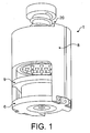
- the extraction module 1 comprises extraction means making it possible to receive a capsule 12 and to extract a liquid extract by applying pressurized water through the capsule.
- the extraction means comprise a first sub-assembly 10, preferably fixed, and a second sub-assembly 11, preferably mobile, cooperating in closing with the sub-assembly 10.
- the sub-assemblies 10, 11 each have a reception area, respectively, 2 and 5, to receive each one side of the capsule at the time of closure.
- the area of reception of the first sub-assembly 10 has opening elements 22 of the capsule, generally raised elements such as a plurality of zones pyramids forming part of a pressure distribution plate 21.
- the fixed sub-assembly 10 has a base or trunk 6 which is crossed by a flow channel 60 to allow the liquid extract to flow out of the extraction chamber.
- the base 6 is secured to a body main 8 on the sides for example, as shown in figure 4.
- the body 8 and the base 6 delimit an interior space 14 with, an insertion side comprising a slot 15 and an ejection side comprising a light outlet 16 for the capsule.
- the body also includes a central bore 80 allowing passage a piston 20 forming part of the mobile extraction sub-assembly.
- the piston is mounted through the bore 80 of the body and is integrally connected an extraction shower 5 comprising a reception area provided with elements piercing 50 intended to open the capsule.
- the piston 20 and the shower 5 are integrally mounted coaxially and have an inlet channel of water 51 arranged so as to distribute water through the shower 5.
- the piston is mounted elastically through the body against a compression spring 150 positioned between a ring 140 fixed to the end of the piston and a housing for the body.
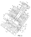
- the seal between the piston and the interior of the body is produced by seals 30, 160 positioned on either side and on the other, an annular baffle formed between the piston and the interior of the body. Between the two seals 30, 160 is thus delimited a pressure chamber 81 expandable under the effect of a hydraulic fluid entering the chamber, which is supplied through a fluid inlet 82 located on the upper body (figure 3).
- the mobile sub-assembly formed essentially piston 20 and shower 5 is held in the open position of the extraction chamber, that is to say, in a position remote from the reception area of the fixed sub-assembly by the compression effect of the spring 150 which acts between the ring 140 of the piston and the body 8.
- the spring 150 which acts between the ring 140 of the piston and the body 8.
- a retaining and positioning element 9 is provided between the mobile sub-assembly 11 and the fixed sub-assembly 10 to retain the capsule in place according to the closing plane P of the module.
- the element of retaining and positioning 9 is arranged so as to stop the capsule along several axes of direction by means of a portion partially partially open cylindrical 90 more particularly visible in the figure 7.
- the element also has an annular guide portion 91 mounted around the base 6 of the fixed extraction sub-assembly. On each side of the element, the element is extended by two fingers 93, 94 along the body 8 which engage in guide grooves 83, 84 of the body.
- These fingers are connected to the upper end of the grooves by return springs elastic 85 allowing, in the module open position, to maintain the retaining and positioning element 9 in a retaining position; that is to say a position in which the cylindrical portion 90 closes partially the space 14, in particular, the exit light 16 as well as the edges in a direction perpendicular to the direction of this light.
- the cylindrical portion 90 of the element is positioned so as to partially surround the reception area 2 of the capsule. It is better to that the portion 90 approaches near the periphery of the reception area and that it has a geometrically complementary shape to the edges 120 of the capsule, preferably, extending over a circumference between 100 and 180 degrees, so as to maintain the capsule along several axes of direction and thus provide some centering of the capsule.
- the portion closes part of the space 14, preferably, so as to be centered on the side opposite to the slot 15.
- the element 9 is thus mounted around the base 6 of coaxially, along an axis I, with respect to the linear displacement of the actuating means of the mobile sub-assembly, that is to say of the piston 20 and shower 5.
- the element 9 is movable along a portion of cylinder 61 of the base between a retaining position and a retracted position allowing closing extraction sub-assemblies around the capsule.
- the element 9 is in the retaining and positioning position of the capsule under the effect of return springs 85 which hold the element at the top of the cylinder portion 61 of the base.
- the extraction module is also provided with an ejection mechanism 7 of the capsule which aims to promote detachment of the capsule after extraction and ejection outside the module.
- Ejection of the capsule should indeed be reliable on an unlimited number of extraction cycles without it it is necessary to carry out a manual removal of a capsule that can get stuck or stuck in the system.
- the ejection mechanism is designed to lift the capsule and peel it off the surface of the receiving area 2.
- the capsule undergoes significant internal pressure due to the accumulation of water in the capsule enclosure; opening the capsule occurring by rupture of the material in contact with the raised elements of the pressure distribution plate. So, after extraction, the surface of the capsule is as stamped in the reliefs of the distribution plate of pressure and you have to apply a force from the surface of the area of outward reception to detach the capsule and eject it.
- the ejection mechanism is configured to be put in elastic tension when closing the two extraction sub-assemblies and be released from this voltage to activate the ejection when the two reopen subassemblies.
- the ejection mechanism 7 consists of a lever 70 comprising a ring portion 71 and an articulated end 72 on a hinge pin 62 of the base 6 of the fixed extraction sub-assembly.
- the lever ring portion has a diameter substantially greater than the area 2 to allow the extraction module to close, but this diameter is less than the diameter of the edges of the capsule to be able engage with the edges and peel off the capsule.
- the lever 70 is housed, in the rest position, in a recess 95 formed in the retaining and positioning element 9.
- the retaining and positioning element is provided elastic elements 92, in the form of blades fixed on the edge of the element 9, which cooperate with the end 72 of the lever.
- the free parts of the elements elastics extend over the recess 95 to be able to come into contact from the end of the lever which has the effect of lifting the ring portion during ejection.
- a locking the retaining and positioning element 9 in position which aims to keep the element 9 in the retracted position when ejection of the capsule by the ejection means.
- the locking mechanism comprises two abutment surfaces 96, 97 positioned at the end of the fingers 93, 94 of the elements. The surfaces 96, 97 cooperate in locking with two pins 86, 87 housed in the guide grooves 83, 84 of the body when element 9 is lowered along the base of the subassembly fixed extraction.
- FIG. 3 shows the module in the open position of the subassemblies extraction.
- the module is preferably in the tilt position by with respect to the horizontal so as to favor the insertion of the capsule as well as its ejection by benefiting from the force of gravity. Tilt may vary between 5 and 90 degrees, preferably 20 and 80 degrees.
- the piston Under the effect of spring compression 150, the piston is held in the retracted position to release sufficient space 14.
- the retaining and centering element 9 is engaged in in the retaining and positioning position of a capsule thanks to the springs 85.
- a capsule can therefore be inserted through the slot 15.
- the edges 120 of the capsule come into abutment against the complementary shaped portion 90 of the element allowing thus centering the capsule in the middle of the extraction zone.
- the capsule therefore rests freely on the receiving zone 2 against the plate pressure distribution 21.
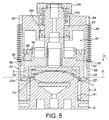
- FIG. 5 shows the module closing phase.
- the piston 20 is activated by introducing hydraulic fluid into the pressure chamber 81.
- the piston drives the shower 5 in closing against the capsule according to the direction F1.
- the retainer and positioning 9 is pushed back by the lower edges of the piston until the element reaches a retracted position at the bottom of the base 6.
- the mobile sub-assembly forces the mechanism under tension ejection 7.
- the shower seal 52 holds the lever 70 in folded position while the elastic elements of elements 9 are subjected elastic bending due to the relative movement of the element 9 with respect to the end 72 of the lever.
- element 9 descends, the end, which is fixed, forces the movable blades 92 to flex; which then energizes the ejection mechanism.
- element 9 is then locked automatically in the retracted position by the locking mechanism. More precisely, the abutment surfaces 96, 97 of the fingers of the element 9 come then cooperate against the abutment surfaces 86, 87 of the body; what immobilizes and locks item 9.
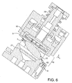
- Figure 6 shows the reopening and ejection phase.
- the reopening is controlled by raising the piston 20 and the shower 5 according to the direction F2.
- Element 9 remains locked by the locking mechanism previously described while the rise of the piston gradually releases the ejection mechanism 7 by the release effect of the blade tension stored during closing.
- Ejection mechanism lever pivots then around the articulation axis 62, which has the effect of taking off the capsule and tilt it further from the vertical side of the exit light 16. The capsule may then fall by gravity into a receptacle for empty capsules (not shown).
- Mechanism action ejection takes place concomitantly with the ascent of the piston.
- the element 9 In end of stroke of the piston, the element 9 is then released by the hooks 220, 221 of the piston which act on the pins 98, 99 which has the effect of removing the fingers 93, 94 and disengage the abutment surfaces. Element 9 is then returned to the retaining and positioning position by the return springs 84, 85.
- the invention relates to an extraction module which can be installed in a machine or beverage dispenser using any type of predosed capsule.
- a machine or dispenser can contain one or more modules according to the capacity required.
- the module of the invention provides more reliable and faster loading / extraction / ejection cycles than those usually known.
Abstract
Description
L'invention se rapporte au domaine de la préparation de boissons utilisant le principe d'extraction d'une substance contenue dans un élément de recharge, appelé communément "capsule", par traversée d'un flux d'eau sous pression. L'invention se rapporte plus particulièrement à un module d'extraction destiné à équiper une machine de préparation de boissons telle qu'une machine à café.The invention relates to the field of the preparation of beverages using the principle of extraction of a substance contained in an element of refill, commonly called "capsule", by crossing a stream of water under pressure. The invention relates more particularly to a module extraction system intended to equip a beverage preparation machine such than a coffee machine.
Il est connu de préparer des boissons telles que du café, du thé ou du chocolat chaud, à partir de capsules contenant une dose prédéterminée d'une substance à extraire. Le format en capsule offre l'avantage de faciliter les opérations de préparation de la boisson, d'assurer une préparation propre, comme sans déchet de marc visible, ainsi que de contrôler la reproductibilité et la qualité du produit préparé.It is known to prepare drinks such as coffee, tea or hot chocolate, from capsules containing a predetermined dose of substance to be extracted. The capsule format offers the advantage of facilitating drink preparation operations, ensuring clean preparation, as without visible marc waste, as well as controlling reproducibility and the quality of the product prepared.
Le principe de l'extraction d'une capsule consiste généralement à (i) enfermer la capsule dans une chambre résistante à la pression, (ii) percer l'une des faces de la capsule, (iii) introduire une quantité d'eau chaude dans la capsule de façon à créer un environnement clos sous pression afin de produire l'extrait liquide de café ou autre, (iv) libérer l'extrait liquide au travers de la face opposée de la capsule et, (v) recueillir l'extrait dans un container de capacité appropriée tel qu'une tasse.The principle of extracting a capsule generally consists of (i) enclose the capsule in a pressure-resistant chamber, (ii) pierce one of the faces of the capsule, (iii) introduce a quantity of hot water into the capsule so as to create a closed environment under pressure to produce the liquid extract of coffee or the like, (iv) release the liquid extract through the opposite side of the capsule and, (v) collect the extract in a container of suitable capacity such as a cup.
Le problème de chargement de la capsule et son évacuation dans le système d'extraction a déjà fait l'objet de nombreuses publications de brevets.The problem of loading the capsule and its evacuation in the extraction system has already been the subject of numerous patent publications.
Dans la demande de brevet EP 1090574 A1, il s'agit d'un dispositif d'extraction comprenant une paire de mâchoires avec une partie de mâchoire fixe et une partie de mâchoire mobile cette dernière étant montée de manière articulée et déportée sur la partie fixe et un mécanisme de levier de fermeture à plusieurs branches est associé pour refermer la partie mobile sur la partie fixe.In patent application EP 1090574 A1, it is a device extraction comprising a pair of jaws with a jaw portion fixed and a movable jaw part the latter being mounted so articulated and offset on the fixed part and a closing lever mechanism with several branches is associated to close the mobile part on the part fixed.
Dans le document publié WO 01/30218 A1, le principe est similaire mais il est prévu, en plus, un mécanisme d'éjection de la capsule associé à un bras de traction de la mâchoire mobile de façon à décoller la capsule du fond de la chambre d'extraction au moment de la réouverture de la mâchoire.In the published document WO 01/30218 A1, the principle is similar but there is also provided a capsule ejection mechanism associated with an arm of traction of the movable jaw so as to detach the capsule from the bottom of the extraction chamber upon reopening of the jaw.
Il ressort de ces principes qu'un dispositif de fermeture à deux parties, dont l'une est fixe et l'autre est mobile, associé ou non à un éjecteur, est connu. Seulement, ces dispositifs sont essentiellement des dispositifs à fermeture manuelle et se prêtent peu à l'automatisation de la fonction de fermeture. Il est aussi à remarquer que du fait du déport des axes d'articulation, de tels systèmes doivent être conçus et montés avec précision de façon à éviter les jeux et les problèmes d'ajustement des pièces.It follows from these principles that a two-part closure device, one of which is fixed and the other of which is mobile, whether or not associated with an ejector, is known. Only, these devices are essentially devices with manual closing and do not lend themselves to the automation of the closing. It should also be noted that due to the offset of the axes of articulation, such systems must be designed and assembled with precision so as to avoid backlash and parts adjustment problems.
La demande de brevet WO 95/17121 se rapporte à un dispositif
comprenant un groupe formé d'un piston fixe et d'un corps cylindrique mobile,
le groupe étant placé en vis-à-vis d'une chaudière. La chaudière, d'une part,
le piston fixe et le corps cylindrique d'autre part, sont séparés par une zone
où sont positionnés les moyens de réception, de maintien en position et
d'éjection des conditionnements. Les moyens de maintien et les moyens de
réception sont des moyens différents; les premiers n'étant pas entièrement
rétractables et étant placés directement entre la chaudière et le corps
cylindrique pour maintenir les bords latéraux du conditionnement, les seconds
étant rétractables et placés sur un côté du corps cylindrique pour simplement
arrêter le conditionnement à l'encontre des forces de gravité. Un tel dispositif
est complexe car il met en jeu différentes pièces pour à la fois retenir et
centrer correctement la capsule (ou conditionnement) en place dans la
chambre d'extraction. Cela implique plusieurs mécanismes séparés de
déplacement des moyens pour permettre de fermer le système d'extraction.
La position décalée des moyens de maintien peut aussi poser des problèmes
de blocage ou d'usure prématurée. De plus, un tel dispositif est aussi
relativement encombrant en raison de la position périphérique du moyen de
maintien et de celle de la chaudière.
La demande de brevet WO 98/47418 se rapporte à un procédé de transformation d'une machine à café express, qui fonctionne en extraction verticale avec des pastilles prédosées utilisées dans un plan horizontal en une machine à café express qui fonctionne en extraction horizontal avec des pastilles pré-dosées utilisables dans un plan vertical. La machine est munie de moyens de réception et d'éjection constitués d'un seul élément escamotable déplaçable en dessous de l'organe d'extraction au moyen d'un moyen électromécanique de manoeuvre séparé des moyens d'actionnement de l'organe d'extraction.Patent application WO 98/47418 relates to a method of transformation of an express coffee machine, which works in extraction vertical with pre-dosed pellets used in a horizontal plane in one express coffee machine which works in horizontal extraction with pre-dosed tablets usable in a vertical plane. The machine is equipped with receiving and ejecting means consisting of a single retractable element movable below the extraction member by means electromechanical maneuver separate from the actuation means the extraction organ.
La demande de brevet WO 00/38558 concerne une chambre d'extraction pour machine automatique composée de deux parties mobiles dans un plan horizontal, dont l'une est alimentée en eau chaude, l'autre possédant un filtre; les deux parties étant montées oscillantes verticalement l'une en face de l'autre selon leur axe transversal.Patent application WO 00/38558 relates to an extraction chamber for automatic machine composed of two moving parts in one plane horizontal, one of which is supplied with hot water, the other having a filter; the two parts being mounted vertically oscillating, one opposite the other along their transverse axis.
La demande de brevet WO 00/44868 se rapporte à un dispositif d'extraction comportant une chambre d'extraction composée de deux parties mobiles dans un mouvement horizontal de manière à pouvoir s'écarter ou se rapprocher l'une de l'autre; les parties étant montées sur un arbre excentrique apte à leur transmettre des mouvements oscillatoires de sens inverses, et le dispositif comportant une liaison pivot freinée entre chaque arbre à excentrique et chaque partie mobile, afin de combiner un mouvement horizontal et un mouvement oscillatoire pour l'enchaínement des phases d'ouverture et de fermeture de la chambre d'extraction.Patent application WO 00/44868 relates to a device extraction chamber comprising an extraction chamber composed of two parts movable in a horizontal movement so as to be able to move away or bring one closer to the other; the parts being mounted on an eccentric shaft able to transmit oscillatory movements in opposite directions to them, and the device comprising a braked pivot connection between each shaft to eccentric and each moving part, in order to combine a movement horizontal and an oscillatory movement for the sequence of phases opening and closing of the extraction chamber.
La présente invention vise à proposer un dispositif d'extraction facilitant l'insertion, le positionnement correct et l'éjection d'une capsule tout en remédiant aux inconvénients des dispositifs de l'art antérieur.The present invention aims to provide an extraction device facilitating insertion, correct positioning and ejection of a capsule while overcoming the disadvantages of the devices of the prior art.
Pour cela, l'invention se rapporte à un module d'extraction sous pression
pour la préparation d'une boisson à partir d'une capsule contenant une
substance à extraire comprenant :
Ainsi, à la différence des dispositifs connus de l'art antérieur, l'alignement selon un même axe de déplacement permet au dispositif de gagner en fiabilité en évitant les blocages et aussi de gagner en réduction de l'encombrement. Le premier sous-ensemble peut comprendre une base sur laquelle le moyen de retenue et de positionnement peut être monté et guidé en glissement pour se déplacer le long de cette base.Thus, unlike the known devices of the prior art, alignment along the same axis of movement allows the device to gain reliability by avoiding blockages and also gain reduction in clutter. The first subset may include a base on which the retaining and positioning means can be mounted and guided in sliding to move along this base.
De manière préférentielle, le moyen de retenue et de positionnement est configuré comme un seul élément capable de retenir en centrage la capsule dans l'espace d'ouverture selon plusieurs axes selon le plan de fermeture.Preferably, the retaining and positioning means is configured as a single element capable of centering the capsule in the opening space along several axes according to the closing plane.
Ainsi, les fonctions retenue et de positionnement selon plusieurs axes de direction sont assurées par un seul élément; ce qui rend le dispositif plus simple, plus fiable et plus compact.Thus, the functions retained and positioning along several axes of direction are provided by a single element; which makes the device more simple, more reliable and more compact.
La retenue et le centrage correct de la capsule selon plusieurs directions dans le plan de fermeture peut être obtenu, par exemple, par un moyen de retenue et de positionnement possédant une portion de cylindre ouvert destinée à retenir et centrer la capsule et une portion de guidage annulaire montée autour de la base du sous-ensemble d'extraction.The correct retention and centering of the capsule in several directions in the closure plan can be obtained, for example, by a means of restraint and positioning having an open cylinder portion intended to retain and center the capsule and an annular guide portion mounted around the base of the extraction sub-assembly.
Dans un mode préférentiel, des moyens d'éjection de la capsule sont prévus pour éjecter la capsule en dehors du module. La capsule étant sensiblement humide et appliquée intimement contre les surfaces des moyens d'extraction en raison de l'effet de pression, les moyens d'éjection permettent de décoller la capsule après chaque extraction. Les moyens d'éjection permettent aussi d'assister à l'expulsion de la capsule même à des inclinaisons faibles du module par rapport à l'horizontale.In a preferred embodiment, means for ejecting the capsule are designed to eject the capsule outside the module. The capsule being appreciably damp and applied intimately against the surfaces of the means due to the pressure effect, the ejection means allow take off the capsule after each extraction. Ejection means also allow to witness the expulsion of the capsule even at inclinations weak of the module compared to the horizontal.
De préférence, les moyens d'éjection pour éjecter la capsule sont commandés, lors de l'ouverture, par l'action de retour linéaire en dégagement du second sous-ensemble mobile par rapport au premier sous-ensemble d'extraction. Cette configuration participe aussi à la simplification du système.Preferably, the ejection means for ejecting the capsule are controlled, during opening, by the linear return action in release of the second mobile subset relative to the first subset extraction. This configuration also contributes to the simplification of the system.
Plus spécifiquement, le moyen de retenue et de positionnement est verrouillé, en position repoussée, lors de la fermeture des sous-ensembles d'extraction et est déverrouillé, en position de retenue, seulement après l'éjection de la capsule par les moyens d'éjection. Le déverrouillage du moyen de retenue et de positionnement en position repoussée peut être réalisé directement par l'action de retour linéaire en dégagement du sous-ensemble d'extraction mobile. Le moyen de retenue et de positionnement peut alors retourner en position de retenue sous l'effet de rappel d'un moyen élastique tel qu'un ou plusieurs ressorts de rappel ou tout moyen équivalent. More specifically, the retaining and positioning means is locked, in the pushed-back position, when closing the sub-assemblies and is unlocked, in the retaining position, only after ejection of the capsule by the ejection means. Unlocking the medium restraint and positioning in the pushed-back position can be achieved directly by the linear return action in release of the subset mobile extraction. The retaining and positioning means can then return to the retaining position under the return effect of an elastic means such as one or more return springs or any equivalent means.
L'indexation de la commande de déverrouillage du moyen de retenue et de positionnement par rapport à l'éjection de la capsule conduit à un automatisme contrôlé et séquentiel fiable qui permet de s'assurer que l'éjection de la capsule se fait alors qu'un espace suffisant est laissé entre les sous-ensembles d'extraction et que le moyen de retenue et de positionnement n'est pas encore replacé en position de retenue d'une nouvelle capsule.Indexing the unlocking control of the retaining means and positioning with respect to the ejection of the capsule leads to a controlled and reliable sequential automation that ensures that the capsule is ejected while sufficient space is left between the extraction sub-assemblies and that the retaining and positioning means has not yet been returned to the retaining position of a new capsule.
L'actionnement des moyens d'éjection peut revêtir différentes formes. Dans un exemple préférentiel, les moyens d'éjection sont mis en tension élastique lors de la fermeture des deux sous-ensembles d'extraction et libérés de leur tension élastique pour activer l'éjection au moment de la réouverture des deux sous-ensembles. L'avantage d'un tel principe est de permettre d'indexer l'éjection à l'ouverture des sous-ensemble d'extraction sans avoir à recourir à un mécanisme séparé de commande de l'éjection ou de contrôle électrique ou électronique de l'ouverture. Par exemple, les moyens d'éjection peuvent être constitués d'un levier en forme de bague, articulé sur le sous-ensemble d'extraction fixe. Le levier peut être mis en tension au contact d'au moins une lame élastique ou tout autre moyen équivalent supporté par le moyen de retenue et de positionnement.The actuation of the ejection means can take different forms. In a preferred example, the ejection means are tensioned elastic when closing the two extraction sub-assemblies and released from their elastic tension to activate ejection at the time of reopening of the two sub-assemblies. The advantage of such a principle is allow the ejection to be indexed when the extraction sub-assembly is opened without having to use a separate ejection control or electric or electronic opening control. For example, the means ejection may consist of a ring-shaped lever, articulated on the fixed extraction sub-assembly. The lever can be tensioned at contact of at least one elastic blade or any other equivalent means supported by the retaining and positioning means.
Le sous-ensemble d'extraction mobile comprend, de préférence, des moyens d'actionnement linéaires, de préférence du type à piston, activables en fermeture par des moyens hydrauliques ou électriques.The mobile extraction sub-assembly preferably includes linear actuation means, preferably of the piston type, activatable by closing by hydraulic or electric means.
Dans un mode préféré, le premier sous-ensemble d'extraction est fixe. Il comprend une zone de réception de la capsule muni d'éléments en relief pour l'ouverture de la capsule. Le second sous-ensemble mobile comprend une zone de réception complémentaire de la capsule et des moyens d'alimentation en eau de la capsule.In a preferred mode, the first extraction subset is fixed. he includes a capsule reception area with raised elements for the opening of the capsule. The second mobile sub-assembly includes a complementary reception area of the capsule and the supply means in capsule water.
D'autres caractéristiques et avantages de l'invention seront mieux
compris en regard des dessins annexés ci-joints qui représentent un exemple
préféré de l'invention.
En référence aux figures 1 à 5, le module d'extraction 1 comprend des
moyens d'extraction permettant de réceptionner une capsule 12 et d'en
extraire un extrait liquide par application d'eau sous pression au travers de la
capsule. Les moyens d'extraction comportent un premier sous-ensemble 10,
de préférence, fixe, et un second sous-ensemble 11, de préférence, mobile,
coopérant en fermeture avec le sous-ensemble 10. Les sous-ensembles 10,
11 ont chacun une zone de réception, respectivement, 2 et 5, pour recevoir
chacun une face de la capsule au moment de la fermeture. La zone de
réception du premier sous-ensemble 10 possède des éléments d'ouverture 22
de la capsule, en général des éléments en relief tels qu'une pluralité de zones
pyramidales faisant partie d'une plaque de distribution de pression 21.With reference to FIGS. 1 to 5, the
Le sous-ensemble fixe 10 possède une base ou tronc 6 laquelle est
traversée par un canal d'écoulement 60 pour permettre à l'extrait liquide de
s'écouler de la chambre d'extraction. La base 6 est solidarisée à un corps
principal 8 sur les côtés par exemple, comme le montre la figure 4. Le corps 8
et la base 6 délimitent un espace intérieur 14 avec, un côté d'insertion
comprenant une fente 15 et un côté d'éjection comprenant une lumière de
sortie 16 pour la capsule.The fixed
Le corps comprend aussi un alésage central 80 permettant le passage
d'un piston 20 faisant partie du sous-ensemble d'extraction mobile. Le piston
est monté au travers de l'alésage 80 du corps et est relié de manière solidaire
à une douche d'extraction 5 comprenant une zone réception munis d'éléments
de perçage 50 destinés à ouvrir la capsule. Le piston 20 et la douche 5 sont
montés solidairement de manière coaxiale et possèdent un canal d'arrivée
d'eau 51 agencé de manière à distribuer de l'eau au travers de la douche 5.The body also includes a central bore 80 allowing passage
a
Le piston est monté élastiquement au travers du corps à l'encontre d'un
ressort de compression 150 positionné entre une bague 140 fixée à
l'extrémité du piston et un logement du corps. L'étanchéité entre le piston et
l'intérieur du corps est réalisée par des joints 30, 160 positionnés de part et
d'autre d'une chicane annulaire formée entre le piston et l'intérieur du corps.
Entre les deux joints 30, 160 est ainsi délimité une chambre de pression 81
expansible sous l'effet d'un fluide hydraulique entrant dans la chambre, lequel
est alimenté au travers d'une entrée de fluide 82 située sur le haut du corps
(figure 3).The piston is mounted elastically through the body against a
On comprend donc que le sous-ensemble mobile formé essentiellement
du piston 20 et de la douche 5 est maintenu en position d'ouverture de la
chambre d'extraction, c'est à dire, en position éloignée de la zone de réception
du sous-ensemble fixe par l'effet de compression du ressort 150 qui agit
entre la bague 140 du piston et le corps 8. De la sorte, en appliquant un fluide
hydraulique dans la chambre de pression 81, le ressort est comprimé de façon
à pousser solidairement le piston et la douche dans la direction de fermeture
F1.We therefore understand that the mobile sub-assembly formed essentially
Dans la configuration d'ouverture des figures 1 à 3, un espace suffisant
14 est maintenu entre les deux zones de réception opposées 2, 5 pour pouvoir
insérer une capsule 12 au travers de la fente 15. L'insertion de la capsule au
travers de la fente 15 peut être réalisée de façon manuelle, par l'utilisateur
lui-même, ou par des moyens de convoyage semi-automatiques ou
automatiques non-décrits dans la présente demande.In the opening configuration of Figures 1 to 3,
Selon l'invention, un élément de retenue et de positionnement 9 est prévu
entre le sous-ensemble mobile 11 et le sous-ensemble fixe 10 pour retenir la
capsule en place selon le plan de fermeture P du module. L'élément de
retenue et de positionnement 9 est agencé de manière à arrêter la capsule
selon plusieurs axes de direction au moyen d'une portion partiellement
cylindrique partiellement ouverte 90 plus particulièrement visible sur la figure
7. L'élément possède d'autre part une portion de guidage annulaire 91 montée
autour de la base 6 du sous-ensemble d'extraction fixe. De chaque côté de
l'élément, l'élément se prolonge par deux doigts 93, 94 le long du corps 8
lesquels s'engagent dans des rainures de guidage 83, 84 du corps. Ces doigts
sont reliés à l'extrémité supérieure des rainures par des ressorts de rappels
élastiques 85 permettant, en position d'ouverture du module, de maintenir
l'élément de retenue et de positionnement 9 dans une position de retenue;
c'est à dire une position dans laquelle la portion cylindrique 90 obture
partiellement l'espace 14, en particulier, la lumière de sortie 16 ainsi que les
bords en direction perpendiculaire à la direction de cette lumière.According to the invention, a retaining and
La portion cylindrique 90 de l'élément est positionnée de manière à
entourer partiellement la zone de réception 2 de la capsule. Il est préférable
que la portion 90 s'approche près de la périphérie de la zone de réception et
qu'elle ait une forme géométriquement complémentaire des bords 120 de la
capsule, de préférence, en s'étendant sur une circonférence comprise entre
100 et 180 degrés, de façon à maintenir la capsule selon plusieurs axes de
direction et fournir ainsi un certain centrage de la capsule. La portion obture
une partie de l'espace 14, préférentiellement, de manière à être centrée du
côté opposé à la fente 15. L'élément 9 est ainsi monté autour de la base 6 de
manière coaxiale, selon un axe I, par rapport au déplacement linéaire des
moyens d'actionnement du sous-ensemble mobile, c'est à dire du piston 20 et
de la douche 5.The
L'élément 9 est déplaçable le long d'une portion de cylindre 61 de la base
entre une position de retenue et une position rétractée autorisant la fermeture
des sous-ensembles d'extraction autour de la capsule. Dans la configuration
des figures 1 et 2, l'élément 9 est en position de retenue et de positionnement
de la capsule sous l'effet des ressorts de rappel 85 qui maintiennent l'élément
en haut de la portion cylindre 61 de la base.The
Le module d'extraction est muni aussi d'un mécanisme d'éjection 7 de la
capsule qui a pour but de favoriser le décollement de la capsule après
l'extraction et son éjection en dehors du module. L'éjection de la capsule doit
en effet être fiable sur une nombre illimité de cycles d'extraction sans qu'il
soit nécessaire de procéder à un enlèvement manuel d'une capsule pouvant
être coincé ou collé dans le système. Le mécanisme d'éjection est prévu pour
soulever la capsule et la décoller de la surface de la zone de réception 2. Lors
de l'extraction, la capsule subit une pression importante en interne due à
l'accumulation de l'eau dans l'enceinte de la capsule; l'ouverture de la capsule
ayant lieu par rupture du matériau au contact des éléments en relief de la
plaque de répartition de pression. Ainsi, après extraction, la surface de la
capsule est comme emboutie dans les reliefs de la plaque de distribution de
pression et il faut appliquer une force à partir de la surface de la zone de
réception vers l'extérieur pour décoller la capsule et l'éjecter.The extraction module is also provided with an
Le mécanisme d'éjection est configuré pour être mis en tension élastique
lors de la fermeture des deux sous-ensembles d'extraction et être libérés de
cette tension pour activer l'éjection au moment de la réouverture des deux
sous-ensembles. Pour cela, le mécanisme d'éjection 7 est constitué d'un
levier 70 comprenant une portion de bague 71 et une extrémité 72 articulée
sur un axe d'articulation 62 de la base 6 du sous-ensemble d'extraction fixe.
La portion de bague du levier a un diamètre sensiblement supérieur à la zone
de réception 2 pour permettre la fermeture du module d'extraction, mais ce
diamètre est inférieur au diamètre des bords de la capsule pour pouvoir
s'engager avec les bords et décoller la capsule. De manière préférentielle, le
levier 70 se loge, en position de repos, dans un retrait 95 formé dans
l'élément de retenue et de positionnement 9. Pour déclencher le levier en
position d'éjection, l'élément de retenue et de positionnement est muni
d'éléments élastiques 92, en forme de lames fixées sur le rebord de l'élément
9, qui coopèrent avec l'extrémité 72 du levier. Les parties libres des éléments
élastiques se prolongent au dessus du retrait 95 pour pouvoir venir au contact
de l'extrémité du levier ce qui a pour effet de soulever la portion de bague
lors de l'éjection.The ejection mechanism is configured to be put in elastic tension
when closing the two extraction sub-assemblies and be released from
this voltage to activate the ejection when the two reopen
subassemblies. For this, the
Comme le montre les figures 2 et 4, il est prévu un mécanisme de
verrouillage de l'élément de retenue et de positionnement 9 en position
rétractée qui a pour but de maintenir l'élément 9 en position rétractée lors de
l'éjection de la capsule par le moyen d'éjection. Le mécanisme de verrouillage
comprend deux surfaces de butées 96, 97 positionnées à l'extrémité des
doigts 93, 94 de l'éléments. Les surfaces 96, 97 coopèrent en verrouillage
avec deux ergots 86 , 87 logés dans les rainures de guidage 83, 84 du corps
lorsque l'élément 9 est abaissé le long de la base du sous-ensemble
d'extraction fixe.As shown in Figures 2 and 4, there is provided a
locking the retaining and
Enfin, il est aussi prévu un mécanisme de déverrouillage de l'élément de
retenue et de positionnement 9 qui permet à celui-ci de recouvrer sa position
initiale de retenue et de positionnement des figures 1 et 2. Ce mécanisme
comprend des ergots 98, 99 à l'intérieur des doigts de l'élément 9 destinés à
être activés par des crochets 220, 221 positionnés sur le pourtour du piston
lors de la remontée du piston.Finally, there is also provided a mechanism for unlocking the element of
restraint and
Le principe de fonctionnement du module d'extraction va maintenant être détaillé pour une meilleure compréhension des phases d'insertion, de fermeture, d'ouverture et d'éjection de la capsule.The operating principle of the extraction module will now be detailed for a better understanding of the phases of insertion, closing, opening and ejection of the capsule.
La figure 3 montre le module en position d'ouverture des sous-ensemble
d'extraction. Le module est préférablement en position d'inclinaison par
rapport à l'horizontale de façon à favoriser l'insertion de la capsule ainsi que
son éjection en bénéficiant de la force de gravité. L'inclinaison peut varier
entre 5 et 90 degrés, préférablement 20 et 80 degrés. Sous l'effet du ressort
de compression 150, le piston est maintenu en position rétractée pour libérer
un espace suffisant 14. L'élément de retenue et de centrage 9 est engagé en
en position de retenue et de positionnement d'une capsule grace aux ressorts
de rappels 85. Une capsule peut donc être insérée au travers de la fente 15.
Lors de l'insertion d'une capsule, les bords 120 de la capsule viennent en
butée contre la portion de forme complémentaire 90 de l'élément permettant
ainsi un centrage de la capsule au milieu de la zone d'extraction. La capsule
repose donc librement sur la zone de réception 2 contre la plaque de
répartition de pression 21.Figure 3 shows the module in the open position of the subassemblies
extraction. The module is preferably in the tilt position by
with respect to the horizontal so as to favor the insertion of the capsule as well as
its ejection by benefiting from the force of gravity. Tilt may vary
between 5 and 90 degrees, preferably 20 and 80 degrees. Under the effect of
La figure 5 montre la phase de fermeture du module. Le piston 20 est
activé par introduction d'un fluide hydraulique dans la chambre de pression
81. Le piston entraíne la douche 5 en fermeture contre la capsule selon la
direction F1. Lors de la descente du piston, l'élément de retenue et de
positionnement 9 est repoussé par les bords inférieurs du piston jusqu'à ce
que l'élément atteigne une position rétractée en bas de la base 6. En fin de
fermeture, le sous-ensemble mobile force sous tension le mécanisme
d'éjection 7. En particulier, le joint 52 de douche maintient le levier 70 en
position repliée alors que les éléments élastiques de l'éléments 9 sont soumis
à une flexion élastique due au mouvement relatif de l'élément 9 par rapport à
l'extrémité 72 du levier. Lorsque l'élément 9 descend, l'extrémité, qui elle est
fixe, force les lames mobiles 92 à fléchir; ce qui met alors sous tension le
mécanisme d'éjection.Figure 5 shows the module closing phase. The
Lorsque le module est fermé, l'élément 9 est alors verrouillé
automatiquement en position rétractée par le mécanisme de verrouillage. Plus
précisément, les surfaces de butée 96, 97 des doigts de l'élément 9 viennent
alors coopérer contre les surfaces de butée 86, 87 du corps; ce qui immobilise
et verrouille l'élément 9.When the module is closed,
L'opération d'extraction qui consiste à extraire l'extrait liquide sous pression d'eau chaude est connue en soi et ne nécessite pas d'être détaillée dans la présente demande.The extraction operation which consists in extracting the liquid extract under hot water pressure is known per se and does not need to be detailed in this application.
La figure 6 montre la phase de réouverture et d'éjection. La réouverture
est commandée par la remontée du piston 20 et de la douche 5 selon la
direction F2. L'élément 9 reste verrouillé par le mécanisme de verrouillage
précédemment décrit alors que la remontée du piston libère progressivement
le mécanisme d'éjection 7 par l'effet de relâchement de la tension des lames
emmagasinée lors de la fermeture. Le levier du mécanisme d'éjection pivote
alors autour de l'axe d'articulation 62, ce qui a pour effet de décoller la
capsule et de l'incliner davantage par rapport à la verticale du côté de la
lumière de sortie 16. La capsule peut alors tomber par gravité dans un
réceptacle pour les capsules vides (non représenté). L'action du mécanisme
d'éjection se fait de manière concomitante à la remontée du piston. En fin de
course du piston, l'élément 9 est alors libéré par les crochets 220, 221 du
piston qui agissent sur les ergots 98, 99 ce qui a pour effet d'écarter les
doigts 93, 94 et désengager les surfaces de butées. L'élément 9 est alors
rappelé en position de retenue et de positionnement par les ressorts de rappel
84, 85.Figure 6 shows the reopening and ejection phase. The reopening
is controlled by raising the
L'invention concerne un module d'extraction pouvant être installé dans une machine ou un distributeur de boisson utilisant n'importe quel type de capsule prédosée. Une machine ou distributeur peut contenir un ou plusieurs modules selon la capacité nécessaire. Le module de l'invention procure des cycles de chargement/extraction/éjection plus fiables et plus rapides que ceux habituellement connus.The invention relates to an extraction module which can be installed in a machine or beverage dispenser using any type of predosed capsule. A machine or dispenser can contain one or more modules according to the capacity required. The module of the invention provides more reliable and faster loading / extraction / ejection cycles than those usually known.
Claims (18)
Priority Applications (28)
| Application Number | Priority Date | Filing Date | Title |
|---|---|---|---|
| SI200330174T SI1444932T1 (en) | 2003-02-07 | 2003-02-07 | Linear extraction unit for the preparation under pressure of a drink from a cartridge |
| DK03002817T DK1444932T3 (en) | 2003-02-07 | 2003-02-07 | Extraction module with linear closure to produce a beverage under pressure from a capsule |
| EP03002817A EP1444932B1 (en) | 2003-02-07 | 2003-02-07 | Linear extraction unit for the preparation under pressure of a drink from a cartridge |
| ES03002817T ES2256601T3 (en) | 2003-02-07 | 2003-02-07 | EXCTRACTION MODULE WITH LINEAR CLOSURE TO PREPARE A PRESSURE DRINK FROM A CAPSULE. |
| AT03002817T ATE316349T1 (en) | 2003-02-07 | 2003-02-07 | LINEAR EXTRACTION MODULE FOR PREPARING A DRINK FROM A CARTRIDGE |
| DE60303320T DE60303320T2 (en) | 2003-02-07 | 2003-02-07 | Linear extraction module for preparing a beverage from a cartridge |
| JP2006501575A JP4288280B2 (en) | 2003-02-07 | 2004-01-22 | Extraction module with a linear closure for the preparation of pressurized beverages from capsules |
| AU2004212280A AU2004212280B2 (en) | 2003-02-07 | 2004-01-22 | Extraction module with linear closure for the pressurised preparation of a drink from a capsule |
| US10/544,014 US7562618B2 (en) | 2003-02-07 | 2004-01-22 | Extraction module with linear closure for the pressurised preparation of a drink from a capsule |
| MXPA05007980A MXPA05007980A (en) | 2003-02-07 | 2004-01-22 | Extraction module with linear closure for the pressurised preparation of a drink from a capsule. |
| CA2514147A CA2514147C (en) | 2003-02-07 | 2004-01-22 | Extraction module with linear closure for the pressurised preparation of a drink from a capsule |
| BRPI0407326-6A BRPI0407326A (en) | 2003-02-07 | 2004-01-22 | Extraction module with linear closure for the preparation under pressure of a beverage from a capsule. |
| HU0500841A HUP0500841A2 (en) | 2003-02-07 | 2004-01-22 | Extraction module with linear closure for the pressurised preparation of a drink from a capsule |
| UAA200508557A UA79857C2 (en) | 2003-02-07 | 2004-01-22 | Extraction module with linear closure for pressurised preparation of drink from capsule |
| CZ20050563A CZ2005563A3 (en) | 2003-02-07 | 2004-01-22 | Extraction module |
| RU2005127855/12A RU2339288C2 (en) | 2003-02-07 | 2004-01-22 | Extraction module with linear jointing for high pressure production of beverage from content of capsule |
| CNB200480003653XA CN100496355C (en) | 2003-02-07 | 2004-01-22 | Extraction assembly with linear sealing unit for the preparation under pressure of a drink from a cartridge |
| PL377353A PL377353A1 (en) | 2003-02-07 | 2004-01-22 | Extraction module with linear closure for the pressurised preparation of a drink from a capsule |
| PCT/EP2004/000498 WO2004071259A1 (en) | 2003-02-07 | 2004-01-22 | Extraction module with linear closure for the pressurised preparation of a drink from a capsule |
| TW093102795A TW200507786A (en) | 2003-02-07 | 2004-02-06 | Extraction module with linear closure for the preparation, under pressure, of a beverage from a capsule |
| CL200400216A CL2004000216A1 (en) | 2003-02-07 | 2004-02-06 | EXTRACTION MODULE UNDER PRESSURE FOR THE PREPARATION OF A DRINK FROM A CAPSULE, WHICH INCLUDES MEANS OF RETAINING AND POSITIONING ASSEMBLED AROUND THE BASE OF THE FIRST SUBSTITUTE OF EXTRACTION, SO THAT THESE CAN BE PUSHED |
| ARP040100388A AR043123A1 (en) | 2003-02-07 | 2004-02-06 | LINEAR CLOSURE EXTRACTION MODULE FOR PREPARATION UNDER PRESSURE OF A DRINK FROM A CAPSULE |
| IL169490A IL169490A0 (en) | 2003-02-07 | 2005-06-30 | Extraction module with linear closure for the pressurised preparation of a drink from a capsule |
| BG109238A BG109238A (en) | 2003-02-07 | 2005-07-20 | Extraction module with linear closure for the pressurised preparation of a drink from a capsule |
| NO20054069A NO20054069L (en) | 2003-02-07 | 2005-09-01 | Extractor with linear closure for pressurized preparation of a beverage from a capsule. |
| ZA200507152A ZA200507152B (en) | 2003-02-07 | 2005-09-06 | Extraction module with linear closure for the pressurised preparation of a drink from a capsule |
| US12/392,805 US8256342B2 (en) | 2003-02-07 | 2009-02-25 | Extraction module with linear closure for the pressurized preparation of a drink from a capsule |
| US12/486,478 US8336447B2 (en) | 2003-02-07 | 2009-06-17 | Extraction module with linear closure for the pressurised preparation of a drink from a capsule |
Applications Claiming Priority (1)
| Application Number | Priority Date | Filing Date | Title |
|---|---|---|---|
| EP03002817A EP1444932B1 (en) | 2003-02-07 | 2003-02-07 | Linear extraction unit for the preparation under pressure of a drink from a cartridge |
Publications (2)
| Publication Number | Publication Date |
|---|---|
| EP1444932A1 true EP1444932A1 (en) | 2004-08-11 |
| EP1444932B1 EP1444932B1 (en) | 2006-01-25 |
Family
ID=32605353
Family Applications (1)
| Application Number | Title | Priority Date | Filing Date |
|---|---|---|---|
| EP03002817A Expired - Lifetime EP1444932B1 (en) | 2003-02-07 | 2003-02-07 | Linear extraction unit for the preparation under pressure of a drink from a cartridge |
Country Status (26)
| Country | Link |
|---|---|
| US (3) | US7562618B2 (en) |
| EP (1) | EP1444932B1 (en) |
| JP (1) | JP4288280B2 (en) |
| CN (1) | CN100496355C (en) |
| AR (1) | AR043123A1 (en) |
| AT (1) | ATE316349T1 (en) |
| AU (1) | AU2004212280B2 (en) |
| BG (1) | BG109238A (en) |
| BR (1) | BRPI0407326A (en) |
| CA (1) | CA2514147C (en) |
| CL (1) | CL2004000216A1 (en) |
| CZ (1) | CZ2005563A3 (en) |
| DE (1) | DE60303320T2 (en) |
| DK (1) | DK1444932T3 (en) |
| ES (1) | ES2256601T3 (en) |
| HU (1) | HUP0500841A2 (en) |
| IL (1) | IL169490A0 (en) |
| MX (1) | MXPA05007980A (en) |
| NO (1) | NO20054069L (en) |
| PL (1) | PL377353A1 (en) |
| RU (1) | RU2339288C2 (en) |
| SI (1) | SI1444932T1 (en) |
| TW (1) | TW200507786A (en) |
| UA (1) | UA79857C2 (en) |
| WO (1) | WO2004071259A1 (en) |
| ZA (1) | ZA200507152B (en) |
Cited By (10)
| Publication number | Priority date | Publication date | Assignee | Title |
|---|---|---|---|---|
| EP1721553A1 (en) * | 2005-05-12 | 2006-11-15 | Perfect Steam Appliances Ltd. | Infusion assembly for beverage preparing machine |
| EP1767129A1 (en) | 2005-09-27 | 2007-03-28 | Nestec S.A. | Extraction module for a capsule-based beverage production device |
| EP1859714A1 (en) * | 2006-05-24 | 2007-11-28 | Nestec S.A. | Brewing Device and Brewing Capsule System with a Capsule Holder for Facilitating Insertion and Removal of Capsules |
| EP2037781A1 (en) | 2006-07-06 | 2009-03-25 | Perfect Steam Appliances Ltd. | Infusion assembly for beverage preparing machine |
| WO2009113035A2 (en) * | 2008-03-14 | 2009-09-17 | Monodor S.A. | Apparatus and capsule for making a drink |
| ITBS20080226A1 (en) * | 2008-12-10 | 2010-06-11 | Capitani Srl | INFUSION GROUP |
| WO2011114179A1 (en) * | 2010-03-19 | 2011-09-22 | N&W Global Vending S.P.A. | Infusion assembly |
| RU2506031C2 (en) * | 2009-03-12 | 2014-02-10 | Митака С.Р.Л. | Machine for preparation of beverages by way of brewing using cartridges |
| CN104083086A (en) * | 2014-06-20 | 2014-10-08 | 广东新宝电器股份有限公司 | Puncturing piece for beverage extraction |
| IT202100014012A1 (en) * | 2021-05-28 | 2022-11-28 | Arteq S R L | Dispensing group for machines for the preparation of capsule drinks |
Families Citing this family (81)
| Publication number | Priority date | Publication date | Assignee | Title |
|---|---|---|---|---|
| EP1495702A1 (en) | 2003-07-10 | 2005-01-12 | Nestec S.A. | Device for the extraction of a cartridge |
| ITTO20040374A1 (en) * | 2004-06-04 | 2004-09-04 | Sgl Italia Srl | PERCOLATING MACHINE FOR THE PREPARATION OF A DRINK |
| DK1702543T3 (en) | 2004-10-25 | 2008-01-07 | Nestec Sa | Capsule with sealants |
| PL1839543T3 (en) | 2006-03-31 | 2008-12-31 | Nestec Sa | Capsule with outer sealing material pressurized by a fluid |
| FR2904205B1 (en) * | 2006-07-26 | 2012-04-06 | Cie Mediterraneenne Des Cafes | DEVICE AND METHOD FOR PRODUCING BEVERAGES BY INFUSION |
| ITFI20060194A1 (en) * | 2006-08-04 | 2008-02-05 | Saeco Ipr Ltd | INFUSION DEVICE FOR THE PREPARATION OF DRINKS FROM SINGLE-DOSE CAPSULES |
| DE602006006675D1 (en) * | 2006-08-30 | 2009-06-18 | Nestec Sa | Capsule for making beverages |
| ITFI20070028A1 (en) | 2007-02-07 | 2008-08-08 | Saeco Ipr Ltd | INFUSION DEVICE FOR THE PREPARATION OF DRINKS FROM SINGLE-DOSE CAPSULES WITH A CAPSULES CENTERING DEVICE. |
| EP1967099B1 (en) * | 2007-03-06 | 2010-01-06 | Nestec S.A. | Device for preparing a food liquid from a capsule |
| PT1967100E (en) * | 2007-03-06 | 2009-05-29 | Nestec Sa | System for preparing a beverage from a capsule and method |
| US10722066B2 (en) * | 2010-12-04 | 2020-07-28 | Adrian Rivera | Windowed single serving brewing material holder |
| US11832755B2 (en) * | 2007-07-13 | 2023-12-05 | Adrian Rivera | Brewing material container for a beverage brewer |
| EP2194824B2 (en) * | 2007-08-29 | 2016-02-10 | Nestec S.A. | Dispensing device for preparing and dispensing food and/or nutritional composition |
| PL2205133T3 (en) | 2007-10-04 | 2011-10-31 | Nestec Sa | Beverage brewing unit |
| MX2010003569A (en) | 2007-10-04 | 2010-05-05 | Nestec Sa | Integrated heater for a beverage preparation device. |
| CL2008002963A1 (en) | 2007-10-04 | 2010-01-22 | Nestec Sa | Heating device for a machine for the preparation of liquid food or drink, comprising a thermal unit with a metallic mass, through which the liquid circulates, and accumulates heat and supplies it to the liquid, and has one or more insured electrical components rigidly to the thermal unit; and machine. |
| DK2071988T3 (en) * | 2007-12-18 | 2011-04-18 | Nestec Sa | Apparatus for the manufacture of a beverage having a removable injection element |
| CN102036589A (en) * | 2008-01-15 | 2011-04-27 | 雀巢产品技术援助有限公司 | Sealing adapter for a beverage extraction system suitable for preparing a beverage from cartridges |
| EP2105074B1 (en) * | 2008-03-28 | 2011-07-20 | Delica AG | Device and array for preparing a liquid food or luxury article and portion packaging |
| AU2009240123B2 (en) * | 2008-04-22 | 2015-06-25 | Nestec S.A. | Modular assembly of a beverage preparation machine |
| PT2309900E (en) * | 2008-08-08 | 2015-07-30 | Nestec Sa | Beverage machine with carrying handle and configurable appearance&side functions |
| PT2348930E (en) * | 2008-09-13 | 2013-07-18 | Ethical Coffee Company Sa | Device for preparing a drink |
| IT1392573B1 (en) * | 2008-12-30 | 2012-03-09 | Lavazza Luigi Spa | INFUSION GROUP FOR A DRINK PREPARATION MACHINE |
| CN201356446Y (en) * | 2008-12-30 | 2009-12-09 | 薛胜利 | Novel capsule-type coffee maker |
| IT1392572B1 (en) * | 2008-12-30 | 2012-03-09 | Lavazza Luigi Spa | INFUSION GROUP FOR A DRINK PREPARATION MACHINE |
| US8721568B2 (en) | 2009-03-31 | 2014-05-13 | Depuy (Ireland) | Method for performing an orthopaedic surgical procedure |
| US8551023B2 (en) * | 2009-03-31 | 2013-10-08 | Depuy (Ireland) | Device and method for determining force of a knee joint |
| DK2778098T3 (en) * | 2009-06-17 | 2019-01-28 | Douwe Egberts Bv | SYSTEM AND PROCEDURE FOR PREPARING A PRESCRIBED QUANTITY OF BEVERAGE |
| ES2432674T3 (en) * | 2009-07-23 | 2013-12-04 | Ethical Coffee Company Sa | Device for preparing a beverage extracted from a capsule |
| BR112012007816A2 (en) * | 2009-10-05 | 2016-08-30 | Nestec Sa | ergonomic capsule extraction device |
| AU2010305496B2 (en) * | 2009-10-05 | 2014-12-04 | Société des Produits Nestlé S.A. | Cartridge extraction device |
| FR2960402B1 (en) * | 2010-05-25 | 2013-01-11 | Cie Mediterraneenne Des Cafes | INFUSION BEVERAGE PRODUCTION SYSTEM |
| IT1400432B1 (en) * | 2010-06-01 | 2013-05-31 | Lavazza Luigi Spa | INFUSION SYSTEM FOR A DRINK PREPARATION MACHINE. |
| IT1400433B1 (en) * | 2010-06-01 | 2013-05-31 | Lavazza Luigi Spa | INFUSION SYSTEM FOR A DRINK PREPARATION MACHINE. |
| SI3521207T1 (en) * | 2010-07-22 | 2020-07-31 | K-Fee System Gmbh | Portion capsule with barcode |
| DE112011102829T5 (en) * | 2010-08-27 | 2013-07-11 | Nestec S.A. | Controlled motorized brewing unit |
| CN101953638B (en) * | 2010-09-26 | 2013-05-01 | 广东新宝电器股份有限公司 | Funnel of coffee machine |
| CN103298380B (en) * | 2010-10-08 | 2016-08-03 | Qbo咖啡有限责任公司 | Extraction equipment and sealing system |
| US9510705B2 (en) * | 2011-04-13 | 2016-12-06 | Patrick J. Rolfes | Pre-packaged beverage brewer press |
| JP2014522689A (en) * | 2011-07-12 | 2014-09-08 | ネステク ソシエテ アノニム | Actuator for closing beverage ingredient holder |
| ITTV20110105A1 (en) * | 2011-07-21 | 2013-01-22 | Hausbrandt Trieste 1829 Spa | DEVICE FOR THE DRILLING OF A SINGLE-DOSE CAPSULE FOR A POWDER AND SIMILAR SUBSTANCE |
| RU2611266C9 (en) * | 2011-08-25 | 2017-04-17 | Нестек С.А. | Cartridge positioning system |
| JP2014524319A (en) * | 2011-08-25 | 2014-09-22 | ネステク ソシエテ アノニム | Long lasting cartridge punch |
| FR2988988B1 (en) * | 2012-04-04 | 2014-06-27 | Technopool Sarl | BEVERAGE INFUSION BEVERAGE PREPARATION DEVICE WITH SWIVEL CRADLE |
| AU2013329853A1 (en) * | 2012-10-09 | 2015-04-23 | Nestec S.A. | Beverage machine |
| CA2890602C (en) * | 2012-11-13 | 2021-01-26 | Nestec S.A. | Opener for making large openings in capsules |
| CN104510351B (en) * | 2013-09-30 | 2017-09-22 | 胡剑彧 | A kind of extraction mechanism of coffee machine |
| EP2856917A1 (en) * | 2013-10-01 | 2015-04-08 | Luna Technology Systems LTS GmbH | Brewing module |
| PT107335B (en) * | 2013-12-02 | 2020-07-13 | Novadelta - Comércio E Indústria De Cafés, Lda. | SIMPLIFIED CONSTRUCTION EXTRACTION DEVICE AND BEVERAGE PREPARATION SYSTEM INCLUDING THIS DEVICE |
| PT107334B (en) * | 2013-12-02 | 2020-05-12 | Novadelta - Comércio E Indústria De Cafés, Lda. | SIMPLIFIED PERFORMANCE EXTRACTION DEVICE AND OPERATION PROCESS FOR THIS |
| PT3166458T (en) | 2014-07-09 | 2021-06-29 | Nestle Sa | Coupling of a device for connecting a beverage machine to a distribution network |
| ES2828253T3 (en) | 2014-07-09 | 2021-05-25 | Nestle Sa | Device for connecting a beverage machine to a distribution network with safe flow interruption |
| WO2016005349A1 (en) | 2014-07-09 | 2016-01-14 | Nestec S.A. | Accessory for supplying automatically a beverage machine with liquid from a distribution network |
| WO2016005350A1 (en) | 2014-07-09 | 2016-01-14 | Nestec S.A. | Device for connecting a beverage machine to a distribution network with safe monitoring |
| BR102014018473B1 (en) * | 2014-07-28 | 2022-02-08 | B.Blend Máquinas E Bebidas S.A. | REMOVABLE DEVICE FOR SUPPORTING BEVERAGE CAPSULES |
| WO2016051290A1 (en) * | 2014-09-29 | 2016-04-07 | Luigi Lavazza S.P.A. | Dispensing assembly for machines for the preparation of liquid food products |
| TR201908051T4 (en) * | 2014-10-08 | 2019-06-21 | Nestec Sa | Extraction Unit of Beverage Preparation Machine. |
| EP3209171B1 (en) * | 2014-10-20 | 2021-03-10 | Bedford Systems LLC | Cartridge holder for beverage machine |
| ES2570877B1 (en) * | 2014-11-17 | 2017-03-03 | Bonesil Expansion, S.L. | Procedure of elaboration and conservation of olive paste |
| CN107848780A (en) * | 2015-04-13 | 2018-03-27 | 理查兹公司 | Capsule oppening apparatus |
| CN105193272A (en) * | 2015-05-28 | 2015-12-30 | 宁波西文电器有限公司 | Capsule box set arrangement and extraction mechanism |
| ITUB20155389A1 (en) * | 2015-11-09 | 2017-05-09 | Sarong Spa | CAPPULE FOR BEVERAGES |
| AU2016353456B2 (en) | 2015-11-11 | 2022-02-24 | Société des Produits Nestlé S.A. | Easy connection of a liquid tank to a beverage machine |
| US10059404B2 (en) | 2016-03-24 | 2018-08-28 | Mission LLC | Wake diverter |
| USD864838S1 (en) | 2016-03-24 | 2019-10-29 | Mission LLC | Wake diverter |
| PT109303B (en) * | 2016-04-07 | 2021-02-15 | Novadelta Comercio Ind Cafes Sa | EXTRACTION DEVICE WITH MOBILE CAPSULE SUPPORT |
| RU2754461C1 (en) | 2016-11-09 | 2021-09-02 | Пепсико, Инк. | Devices, methods and systems for preparation of carbonated beverages |
| US10183726B1 (en) | 2017-08-29 | 2019-01-22 | Mcnaughton Incorporated | Wake shaping apparatus and related technology |
| FR3075492B1 (en) * | 2017-12-20 | 2020-01-03 | Silec Cable | DEVICE FOR STRIPPING A CABLE |
| WO2019121385A1 (en) * | 2017-12-22 | 2019-06-27 | Societe Des Produits Nestle S.A. | Multi-serve airtight coffee dispenser |
| US11284735B2 (en) * | 2018-12-27 | 2022-03-29 | Rockwell Collins, Inc. | Brew head assembly |
| KR102259987B1 (en) * | 2019-11-15 | 2021-06-02 | 청호나이스 주식회사 | Apparatus of extracting beverage from capsule containing raw material for beverage |
| USD953960S1 (en) | 2020-03-09 | 2022-06-07 | Swell Ventures LLC | Water flow deflection device |
| US11225307B2 (en) | 2020-03-13 | 2022-01-18 | Swell Ventures LLC | Water flow deflection device for a watercraft and methods of use |
| USD953961S1 (en) | 2020-03-13 | 2022-06-07 | Swell Ventures LLC | Adjustable water flow deflection device |
| US11214338B2 (en) | 2020-03-13 | 2022-01-04 | Swell Ventures LLC | Adjustable water flow deflection device for a watercraft and methods of use |
| US11805934B1 (en) * | 2020-10-21 | 2023-11-07 | Adrian Rivera | Brewing material lid and container for a beverage brewer |
| DE102021123554A1 (en) | 2021-09-10 | 2023-03-16 | Eugster / Frismag Ag | Lockable brewing unit |
| AU2022420641A1 (en) * | 2021-12-21 | 2024-04-18 | Société des Produits Nestlé S.A. | Beverage pod system with pod ejector |
| WO2024056537A1 (en) | 2022-09-12 | 2024-03-21 | Société des Produits Nestlé S.A. | Beverage extraction system |
| WO2024056506A1 (en) | 2022-09-12 | 2024-03-21 | Société des Produits Nestlé S.A. | Beverage extraction system |
Citations (4)
| Publication number | Priority date | Publication date | Assignee | Title |
|---|---|---|---|---|
| EP0512142A1 (en) * | 1991-05-08 | 1992-11-11 | Societe Des Produits Nestle S.A. | Method for producing beverages by means of sealed cartridges and apparatus for accomplishing the method |
| US5755149A (en) * | 1993-12-20 | 1998-05-26 | Compagnie Mediterraneenne Des Cafes S.A. | Automatic machine for the preparation of hot beverage infusions |
| US6182554B1 (en) * | 1999-01-19 | 2001-02-06 | Keurig, Inc. | Beverage filter cartridge holder |
| EP1121882A2 (en) * | 2000-02-07 | 2001-08-08 | Petroncini Impianti S.R.L. | Automatic unit for preparing espresso coffee |
Family Cites Families (7)
| Publication number | Priority date | Publication date | Assignee | Title |
|---|---|---|---|---|
| CH673083A5 (en) * | 1987-07-17 | 1990-02-15 | Turmix Ag | |
| FR2709655B1 (en) * | 1993-09-06 | 1995-11-24 | Cafes Cie Mediterraneenne | Express coffee machine using ground coffee packaging of the pre-dosed tablet type. |
| AU2704397A (en) | 1997-04-21 | 1998-11-13 | Compagnie Mediterraneenne Des Cafes (S.A.) | Method for transforming an espresso-coffee maker with vertical coffee extractioninto a machine with horizontal extraction and transformed machine |
| AU1883499A (en) | 1998-12-24 | 2000-07-31 | Compagnie Mediterraneenne Des Cafes (S.A.) | Extraction chamber for an automatic machine preparing hot drinks |
| GB9901702D0 (en) | 1999-01-27 | 1999-03-17 | Reckitt & Colman Inc | Improvements in or relating to organic compositions |
| PT1090574E (en) | 1999-08-31 | 2005-02-28 | Nestle Sa | DEVICE FOR EXTRACTION OF A SUBSTANCE FOR THE PREPARATION OF A DRINK |
| PT1095605E (en) | 1999-10-28 | 2004-11-30 | Nestle Sa | DEVICE FOR CAPSULE EJECTION |
-
2003
- 2003-02-07 DK DK03002817T patent/DK1444932T3/en active
- 2003-02-07 EP EP03002817A patent/EP1444932B1/en not_active Expired - Lifetime
- 2003-02-07 ES ES03002817T patent/ES2256601T3/en not_active Expired - Lifetime
- 2003-02-07 SI SI200330174T patent/SI1444932T1/en unknown
- 2003-02-07 AT AT03002817T patent/ATE316349T1/en not_active IP Right Cessation
- 2003-02-07 DE DE60303320T patent/DE60303320T2/en not_active Expired - Lifetime
-
2004
- 2004-01-22 CN CNB200480003653XA patent/CN100496355C/en not_active Expired - Fee Related
- 2004-01-22 WO PCT/EP2004/000498 patent/WO2004071259A1/en not_active Application Discontinuation
- 2004-01-22 MX MXPA05007980A patent/MXPA05007980A/en active IP Right Grant
- 2004-01-22 UA UAA200508557A patent/UA79857C2/en unknown
- 2004-01-22 CA CA2514147A patent/CA2514147C/en not_active Expired - Fee Related
- 2004-01-22 RU RU2005127855/12A patent/RU2339288C2/en not_active IP Right Cessation
- 2004-01-22 CZ CZ20050563A patent/CZ2005563A3/en unknown
- 2004-01-22 AU AU2004212280A patent/AU2004212280B2/en not_active Ceased
- 2004-01-22 BR BRPI0407326-6A patent/BRPI0407326A/en not_active IP Right Cessation
- 2004-01-22 JP JP2006501575A patent/JP4288280B2/en not_active Expired - Fee Related
- 2004-01-22 US US10/544,014 patent/US7562618B2/en not_active Expired - Fee Related
- 2004-01-22 HU HU0500841A patent/HUP0500841A2/en unknown
- 2004-01-22 PL PL377353A patent/PL377353A1/en unknown
- 2004-02-06 TW TW093102795A patent/TW200507786A/en unknown
- 2004-02-06 CL CL200400216A patent/CL2004000216A1/en unknown
- 2004-02-06 AR ARP040100388A patent/AR043123A1/en unknown
-
2005
- 2005-06-30 IL IL169490A patent/IL169490A0/en unknown
- 2005-07-20 BG BG109238A patent/BG109238A/en unknown
- 2005-09-01 NO NO20054069A patent/NO20054069L/en not_active Application Discontinuation
- 2005-09-06 ZA ZA200507152A patent/ZA200507152B/en unknown
-
2009
- 2009-02-25 US US12/392,805 patent/US8256342B2/en active Active
- 2009-06-17 US US12/486,478 patent/US8336447B2/en active Active
Patent Citations (4)
| Publication number | Priority date | Publication date | Assignee | Title |
|---|---|---|---|---|
| EP0512142A1 (en) * | 1991-05-08 | 1992-11-11 | Societe Des Produits Nestle S.A. | Method for producing beverages by means of sealed cartridges and apparatus for accomplishing the method |
| US5755149A (en) * | 1993-12-20 | 1998-05-26 | Compagnie Mediterraneenne Des Cafes S.A. | Automatic machine for the preparation of hot beverage infusions |
| US6182554B1 (en) * | 1999-01-19 | 2001-02-06 | Keurig, Inc. | Beverage filter cartridge holder |
| EP1121882A2 (en) * | 2000-02-07 | 2001-08-08 | Petroncini Impianti S.R.L. | Automatic unit for preparing espresso coffee |
Cited By (24)
| Publication number | Priority date | Publication date | Assignee | Title |
|---|---|---|---|---|
| EP1721553A1 (en) * | 2005-05-12 | 2006-11-15 | Perfect Steam Appliances Ltd. | Infusion assembly for beverage preparing machine |
| EP1767129A1 (en) | 2005-09-27 | 2007-03-28 | Nestec S.A. | Extraction module for a capsule-based beverage production device |
| JP2007098127A (en) * | 2005-09-27 | 2007-04-19 | Nestec Sa | Extraction module for capsule-based beverage production device |
| JP2013006073A (en) * | 2005-09-27 | 2013-01-10 | Nestec Sa | Extraction module for capsule-based beverage production device |
| US8272319B2 (en) | 2005-09-27 | 2012-09-25 | Nestec S.A. | Extraction module for a capsule-based beverage production device |
| RU2443385C2 (en) * | 2006-05-24 | 2012-02-27 | Нестек С.А. | Device for making beverages and system of tea capsule with capsule holder to simplify insertion and removal of capsules |
| EP1859714A1 (en) * | 2006-05-24 | 2007-11-28 | Nestec S.A. | Brewing Device and Brewing Capsule System with a Capsule Holder for Facilitating Insertion and Removal of Capsules |
| WO2007135135A1 (en) * | 2006-05-24 | 2007-11-29 | Nestec S.A. | Brewing device and brewing capsule system with a capsule holder for facilitating insertion and removal of capsules |
| JP2009537269A (en) * | 2006-05-24 | 2009-10-29 | ネステク ソシエテ アノニム | Infusion device and infusion capsule system with capsule holder for facilitating capsule insertion and removal |
| AU2007253303C1 (en) * | 2006-05-24 | 2015-07-23 | Société des Produits Nestlé S.A. | Brewing device and brewing capsule system with a capsule holder for facilitating insertion and removal of capsules |
| AU2007253303B2 (en) * | 2006-05-24 | 2012-08-02 | Société des Produits Nestlé S.A. | Brewing device and brewing capsule system with a capsule holder for facilitating insertion and removal of capsules |
| EP2037781A1 (en) | 2006-07-06 | 2009-03-25 | Perfect Steam Appliances Ltd. | Infusion assembly for beverage preparing machine |
| WO2009113035A2 (en) * | 2008-03-14 | 2009-09-17 | Monodor S.A. | Apparatus and capsule for making a drink |
| CN101969823A (en) * | 2008-03-14 | 2011-02-09 | 莫诺多尔有限公司 | Apparatus and capsule for making a drink |
| CN101969823B (en) * | 2008-03-14 | 2013-05-29 | 摩考菲股份公司 | Apparatus and capsule for making a drink |
| AU2009223206B2 (en) * | 2008-03-14 | 2014-09-04 | Mocoffee Ag | Apparatus and capsule for making a drink |
| US8875617B2 (en) | 2008-03-14 | 2014-11-04 | Mocoffee Ag | Apparatus and capsule for preparing a drink |
| WO2009113035A3 (en) * | 2008-03-14 | 2009-11-26 | Monodor S.A. | Apparatus and capsule for making a drink |
| ITBS20080226A1 (en) * | 2008-12-10 | 2010-06-11 | Capitani Srl | INFUSION GROUP |
| RU2506031C2 (en) * | 2009-03-12 | 2014-02-10 | Митака С.Р.Л. | Machine for preparation of beverages by way of brewing using cartridges |
| WO2011114179A1 (en) * | 2010-03-19 | 2011-09-22 | N&W Global Vending S.P.A. | Infusion assembly |
| US9271599B2 (en) | 2010-03-19 | 2016-03-01 | N & W Global Vending S.P.A. | Infusion assembly |
| CN104083086A (en) * | 2014-06-20 | 2014-10-08 | 广东新宝电器股份有限公司 | Puncturing piece for beverage extraction |
| IT202100014012A1 (en) * | 2021-05-28 | 2022-11-28 | Arteq S R L | Dispensing group for machines for the preparation of capsule drinks |
Also Published As
Similar Documents
| Publication | Publication Date | Title |
|---|---|---|
| EP1444932B1 (en) | Linear extraction unit for the preparation under pressure of a drink from a cartridge | |
| EP1757212B2 (en) | Device for extracting a capsule | |
| EP1247481B1 (en) | Extraction apparatus with integrated cartridge supply system | |
| EP2020891B1 (en) | Machine for producing espresso-type coffee | |
| EP1310199B1 (en) | Device and method for selecting and extracting a cartridge for preparing a beverage | |
| EP2679120B1 (en) | Appliance and capsule for preparing a beverage | |
| EP2043489B1 (en) | Device and process for brewing a drink | |
| CA2472653C (en) | Device for producing beverage by infusion | |
| FR2998463A1 (en) | BEVERAGE INFUSION BEVERAGE PREPARATION DEVICE WITH SWIVEL CRADLE | |
| FR2745995A1 (en) | Conversion of coffee machine from vertical to horizontal extraction | |
| EP3262994B1 (en) | Device for preparing beverage by brewing a powder contained in a capsule | |
| FR2905844A1 (en) | Infusion preparing machine i.e. espresso coffee machine, has extracting device including engaging units connected to cover to engage with flange of dose which projects with opening of receptacle and to drive dose outside receptacle |
Legal Events
| Date | Code | Title | Description |
|---|---|---|---|
| PUAI | Public reference made under article 153(3) epc to a published international application that has entered the european phase |
Free format text: ORIGINAL CODE: 0009012 |
|
| AK | Designated contracting states |
Kind code of ref document: A1 Designated state(s): AT BE BG CH CY CZ DE DK EE ES FI FR GB GR HU IE IT LI LU MC NL PT SE SI SK TR |
|
| AX | Request for extension of the european patent |
Extension state: AL LT LV MK RO |
|
| 17P | Request for examination filed |
Effective date: 20050211 |
|
| 17Q | First examination report despatched |
Effective date: 20050317 |
|
| AKX | Designation fees paid |
Designated state(s): AT BE BG CH CY CZ DE DK EE ES FI FR GB GR HU IE IT LI LU MC NL PT SE SI SK TR |
|
| GRAP | Despatch of communication of intention to grant a patent |
Free format text: ORIGINAL CODE: EPIDOSNIGR1 |
|
| GRAS | Grant fee paid |
Free format text: ORIGINAL CODE: EPIDOSNIGR3 |
|
| GRAA | (expected) grant |
Free format text: ORIGINAL CODE: 0009210 |
|
| AK | Designated contracting states |
Kind code of ref document: B1 Designated state(s): AT BE BG CH CY CZ DE DK EE ES FI FR GB GR HU IE IT LI LU MC NL PT SE SI SK TR |
|
| REG | Reference to a national code |
Ref country code: GB Ref legal event code: FG4D Free format text: NOT ENGLISH |
|
| REG | Reference to a national code |
Ref country code: CH Ref legal event code: EP |
|
| REG | Reference to a national code |
Ref country code: IE Ref legal event code: FG4D Free format text: LANGUAGE OF EP DOCUMENT: FRENCH |
|
| PG25 | Lapsed in a contracting state [announced via postgrant information from national office to epo] |
Ref country code: MC Free format text: LAPSE BECAUSE OF NON-PAYMENT OF DUE FEES Effective date: 20060228 |
|
| PG25 | Lapsed in a contracting state [announced via postgrant information from national office to epo] |
Ref country code: LU Free format text: LAPSE BECAUSE OF NON-PAYMENT OF DUE FEES Effective date: 20060325 |
|
| REF | Corresponds to: |
Ref document number: 60303320 Country of ref document: DE Date of ref document: 20060413 Kind code of ref document: P |
|
| REG | Reference to a national code |
Ref country code: EE Ref legal event code: FG4A Ref document number: E000238 Country of ref document: EE Effective date: 20060214 |
|
| GBT | Gb: translation of ep patent filed (gb section 77(6)(a)/1977) |
Effective date: 20060403 |
|
| REG | Reference to a national code |
Ref country code: SE Ref legal event code: TRGR |
|
| REG | Reference to a national code |
Ref country code: DK Ref legal event code: T3 |
|
| REG | Reference to a national code |
Ref country code: ES Ref legal event code: FG2A Ref document number: 2256601 Country of ref document: ES Kind code of ref document: T3 |
|
| PLBE | No opposition filed within time limit |
Free format text: ORIGINAL CODE: 0009261 |
|
| STAA | Information on the status of an ep patent application or granted ep patent |
Free format text: STATUS: NO OPPOSITION FILED WITHIN TIME LIMIT |
|
| 26N | No opposition filed |
Effective date: 20061026 |
|
| PG25 | Lapsed in a contracting state [announced via postgrant information from national office to epo] |
Ref country code: GR Free format text: LAPSE BECAUSE OF FAILURE TO SUBMIT A TRANSLATION OF THE DESCRIPTION OR TO PAY THE FEE WITHIN THE PRESCRIBED TIME-LIMIT Effective date: 20060426 |
|
| PG25 | Lapsed in a contracting state [announced via postgrant information from national office to epo] |
Ref country code: HU Free format text: LAPSE BECAUSE OF FAILURE TO SUBMIT A TRANSLATION OF THE DESCRIPTION OR TO PAY THE FEE WITHIN THE PRESCRIBED TIME-LIMIT Effective date: 20060726 |
|
| PG25 | Lapsed in a contracting state [announced via postgrant information from national office to epo] |
Ref country code: CY Free format text: LAPSE BECAUSE OF FAILURE TO SUBMIT A TRANSLATION OF THE DESCRIPTION OR TO PAY THE FEE WITHIN THE PRESCRIBED TIME-LIMIT Effective date: 20060125 |
|
| REG | Reference to a national code |
Ref country code: EE Ref legal event code: HC1A Ref document number: E000238 Country of ref document: EE |
|
| PGFP | Annual fee paid to national office [announced via postgrant information from national office to epo] |
Ref country code: AT Payment date: 20090211 Year of fee payment: 7 Ref country code: DK Payment date: 20090213 Year of fee payment: 7 Ref country code: EE Payment date: 20090119 Year of fee payment: 7 Ref country code: IE Payment date: 20090216 Year of fee payment: 7 |
|
| PGFP | Annual fee paid to national office [announced via postgrant information from national office to epo] |
Ref country code: BG Payment date: 20090130 Year of fee payment: 7 Ref country code: CZ Payment date: 20090128 Year of fee payment: 7 Ref country code: FI Payment date: 20090212 Year of fee payment: 7 Ref country code: PT Payment date: 20090203 Year of fee payment: 7 Ref country code: SI Payment date: 20090202 Year of fee payment: 7 Ref country code: SK Payment date: 20090130 Year of fee payment: 7 |
|
| PGFP | Annual fee paid to national office [announced via postgrant information from national office to epo] |
Ref country code: GB Payment date: 20090204 Year of fee payment: 7 |
|
| PGFP | Annual fee paid to national office [announced via postgrant information from national office to epo] |
Ref country code: BE Payment date: 20090225 Year of fee payment: 7 |
|
| PGFP | Annual fee paid to national office [announced via postgrant information from national office to epo] |
Ref country code: SE Payment date: 20090206 Year of fee payment: 7 Ref country code: TR Payment date: 20090114 Year of fee payment: 7 |
|
| REG | Reference to a national code |
Ref country code: PT Ref legal event code: MM4A Free format text: LAPSE DUE TO NON-PAYMENT OF FEES Effective date: 20100809 |
|
| BERE | Be: lapsed |
Owner name: S.A. *NESTEC Effective date: 20100228 |
|
| REG | Reference to a national code |
Ref country code: DK Ref legal event code: EBP |
|
| EUG | Se: european patent has lapsed | ||
| REG | Reference to a national code |
Ref country code: EE Ref legal event code: MM4A Ref document number: E000238 Country of ref document: EE Effective date: 20100228 |
|
| GBPC | Gb: european patent ceased through non-payment of renewal fee |
Effective date: 20100207 |
|
| PG25 | Lapsed in a contracting state [announced via postgrant information from national office to epo] |
Ref country code: EE Free format text: LAPSE BECAUSE OF NON-PAYMENT OF DUE FEES Effective date: 20100228 |
|
| REG | Reference to a national code |
Ref country code: SI Ref legal event code: KO00 Effective date: 20100917 |
|
| REG | Reference to a national code |
Ref country code: SK Ref legal event code: MM4A Ref document number: E 534 Country of ref document: SK Effective date: 20100207 |
|
| PG25 | Lapsed in a contracting state [announced via postgrant information from national office to epo] |
Ref country code: SI Free format text: LAPSE BECAUSE OF NON-PAYMENT OF DUE FEES Effective date: 20100208 Ref country code: FI Free format text: LAPSE BECAUSE OF NON-PAYMENT OF DUE FEES Effective date: 20100207 Ref country code: CZ Free format text: LAPSE BECAUSE OF NON-PAYMENT OF DUE FEES Effective date: 20100207 Ref country code: SK Free format text: LAPSE BECAUSE OF NON-PAYMENT OF DUE FEES Effective date: 20100207 Ref country code: AT Free format text: LAPSE BECAUSE OF NON-PAYMENT OF DUE FEES Effective date: 20100207 Ref country code: BG Free format text: LAPSE BECAUSE OF NON-PAYMENT OF DUE FEES Effective date: 20100831 |
|
| PG25 | Lapsed in a contracting state [announced via postgrant information from national office to epo] |
Ref country code: PT Free format text: LAPSE BECAUSE OF NON-PAYMENT OF DUE FEES Effective date: 20100809 Ref country code: DK Free format text: LAPSE BECAUSE OF NON-PAYMENT OF DUE FEES Effective date: 20100228 Ref country code: IE Free format text: LAPSE BECAUSE OF NON-PAYMENT OF DUE FEES Effective date: 20100208 |
|
| PG25 | Lapsed in a contracting state [announced via postgrant information from national office to epo] |
Ref country code: BE Free format text: LAPSE BECAUSE OF NON-PAYMENT OF DUE FEES Effective date: 20100228 |
|
| PG25 | Lapsed in a contracting state [announced via postgrant information from national office to epo] |
Ref country code: GB Free format text: LAPSE BECAUSE OF NON-PAYMENT OF DUE FEES Effective date: 20100207 |
|
| PG25 | Lapsed in a contracting state [announced via postgrant information from national office to epo] |
Ref country code: SE Free format text: LAPSE BECAUSE OF NON-PAYMENT OF DUE FEES Effective date: 20100208 |
|
| PG25 | Lapsed in a contracting state [announced via postgrant information from national office to epo] |
Ref country code: TR Free format text: LAPSE BECAUSE OF NON-PAYMENT OF DUE FEES Effective date: 20100207 |
|
| PGFP | Annual fee paid to national office [announced via postgrant information from national office to epo] |
Ref country code: ES Payment date: 20140113 Year of fee payment: 12 |
|
| REG | Reference to a national code |
Ref country code: DE Ref legal event code: R082 Ref document number: 60303320 Country of ref document: DE Representative=s name: ANDRAE WESTENDORP PATENTANWAELTE PARTNERSCHAFT, DE |
|
| REG | Reference to a national code |
Ref country code: FR Ref legal event code: PLFP Year of fee payment: 14 |
|
| REG | Reference to a national code |
Ref country code: ES Ref legal event code: FD2A Effective date: 20160329 |
|
| PG25 | Lapsed in a contracting state [announced via postgrant information from national office to epo] |
Ref country code: ES Free format text: LAPSE BECAUSE OF NON-PAYMENT OF DUE FEES Effective date: 20150208 |
|
| REG | Reference to a national code |
Ref country code: FR Ref legal event code: PLFP Year of fee payment: 15 |
|
| PGFP | Annual fee paid to national office [announced via postgrant information from national office to epo] |
Ref country code: NL Payment date: 20170210 Year of fee payment: 15 |
|
| REG | Reference to a national code |
Ref country code: FR Ref legal event code: PLFP Year of fee payment: 16 |
|
| REG | Reference to a national code |
Ref country code: NL Ref legal event code: MM Effective date: 20180301 |
|
| PG25 | Lapsed in a contracting state [announced via postgrant information from national office to epo] |
Ref country code: NL Free format text: LAPSE BECAUSE OF NON-PAYMENT OF DUE FEES Effective date: 20180301 |
|
| REG | Reference to a national code |
Ref country code: DE Ref legal event code: R082 Ref document number: 60303320 Country of ref document: DE Representative=s name: MITSCHERLICH, PATENT- UND RECHTSANWAELTE PARTM, DE |
|
| PGFP | Annual fee paid to national office [announced via postgrant information from national office to epo] |
Ref country code: IT Payment date: 20190221 Year of fee payment: 17 Ref country code: CH Payment date: 20190215 Year of fee payment: 17 Ref country code: DE Payment date: 20190122 Year of fee payment: 17 Ref country code: FR Payment date: 20190111 Year of fee payment: 17 |
|
| REG | Reference to a national code |
Ref country code: CH Ref legal event code: PFUS Owner name: SOCIETE DES PRODUITS NESTLE S.A., CH Free format text: FORMER OWNER: NESTEC S.A., CH |
|
| REG | Reference to a national code |
Ref country code: DE Ref legal event code: R082 Ref document number: 60303320 Country of ref document: DE Representative=s name: MITSCHERLICH, PATENT- UND RECHTSANWAELTE PARTM, DE Ref country code: DE Ref legal event code: R081 Ref document number: 60303320 Country of ref document: DE Owner name: SOCIETE DES PRODUITS NESTLE S.A., CH Free format text: FORMER OWNER: NESTEC S.A., VEVEY, CH |
|
| REG | Reference to a national code |
Ref country code: DE Ref legal event code: R119 Ref document number: 60303320 Country of ref document: DE |
|
| REG | Reference to a national code |
Ref country code: CH Ref legal event code: PL |
|
| PG25 | Lapsed in a contracting state [announced via postgrant information from national office to epo] |
Ref country code: LI Free format text: LAPSE BECAUSE OF NON-PAYMENT OF DUE FEES Effective date: 20200229 Ref country code: CH Free format text: LAPSE BECAUSE OF NON-PAYMENT OF DUE FEES Effective date: 20200229 |
|
| PG25 | Lapsed in a contracting state [announced via postgrant information from national office to epo] |
Ref country code: FR Free format text: LAPSE BECAUSE OF NON-PAYMENT OF DUE FEES Effective date: 20200229 Ref country code: DE Free format text: LAPSE BECAUSE OF NON-PAYMENT OF DUE FEES Effective date: 20200901 |
|
| PG25 | Lapsed in a contracting state [announced via postgrant information from national office to epo] |
Ref country code: IT Free format text: LAPSE BECAUSE OF NON-PAYMENT OF DUE FEES Effective date: 20200207 |