EP1444875B1 - Gehäusekomponente für eine zu belüftende einrichtung - Google Patents
Gehäusekomponente für eine zu belüftende einrichtung Download PDFInfo
- Publication number
- EP1444875B1 EP1444875B1 EP02779534A EP02779534A EP1444875B1 EP 1444875 B1 EP1444875 B1 EP 1444875B1 EP 02779534 A EP02779534 A EP 02779534A EP 02779534 A EP02779534 A EP 02779534A EP 1444875 B1 EP1444875 B1 EP 1444875B1
- Authority
- EP
- European Patent Office
- Prior art keywords
- passage
- lands
- component according
- wall portion
- webs
- Prior art date
- Legal status (The legal status is an assumption and is not a legal conclusion. Google has not performed a legal analysis and makes no representation as to the accuracy of the status listed.)
- Expired - Lifetime
Links
Images

Classifications
-
- H—ELECTRICITY
- H05—ELECTRIC TECHNIQUES NOT OTHERWISE PROVIDED FOR
- H05K—PRINTED CIRCUITS; CASINGS OR CONSTRUCTIONAL DETAILS OF ELECTRIC APPARATUS; MANUFACTURE OF ASSEMBLAGES OF ELECTRICAL COMPONENTS
- H05K5/00—Casings, cabinets or drawers for electric apparatus
- H05K5/02—Details
- H05K5/0213—Venting apertures; Constructional details thereof
Definitions
- the invention relates to a housing component for a device to be ventilated with a flat wall portion and a perforated passage in the wall portion having a plurality of openings and webs lying between the openings.
- housings typically include at least one perforate passage in a housing wall having a plurality of apertures and webs located between the apertures to permit air flow through the housing. While optimum ventilation of the housing could be achieved through a fully open passage, grid-like vents are generally preferred because they provide some mechanical protection for the devices in the housing and, when metal housings are used, provide electromagnetic shielding of the electrical and electronic Ensure components.
- the openings in the ventilation passages are often formed in the form of slots, the openings should be the smaller, the higher the frequencies of the electromagnetic waves to be shielded by the housing.
- the invention is therefore an object of the invention to provide a design for ventilation passages in the housing walls of electrical or electronic devices to be ventilated for their cooling, which allows a maximum air flow and nevertheless sufficient ensures electromagnetic shielding of the device inside the housing.
- An air flow through the perforated passage is always associated with a pressure drop.
- the invention achieves a minimization of this pressure drop and thus maximizes the flow rates for the cooling of electrical and electronic equipment by increasing the free area relative to the total area of the perforated passage by utilizing the third dimension for the perforated passage.
- the total area of the passage openings is determined by the dimensions of the respective side edges of the webs, which delimit the passage openings, and thus essentially by the length dimensions of the webs.
- the base area of the entire perforated passage remains unchanged.
- the net clearance area for the air flow is determined by the slits delimited by the webs, measured perpendicularly to the effective surface of the webs, whereby the bending results in an extension of the webs and thus an increase in the surface area and thus the free area.
- the base area of the perforated passage as a whole is unchanged, the proportion of effective free area increases without significant reduction in the width of the webs.
- the housing of electrical and electronic devices also serves to shield electromagnetic fields.
- the housing is usually made of metal.
- the proportion of the effective free area can be significantly increased without impairing the electromagnetic shielding effect.
- the effective shielding is determined by the largest "open diameter" in the housing wall. Since the perforated passage design according to the invention does not change this largest open diameter, the invention has no negative influence on the electromagnetic shielding effect.
- the housing component according to the invention is preferably used in metal housings for electrical and electronic devices and in particular power supplies, computers and the like. It is applicable in all cases in which electrical or electronic components are to be cooled by means of an air flow, wherein the air flow can be generated by a fan or by free convection.
- the inventive design of the perforated passage of the flow resistance is significantly reduced.
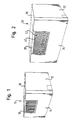
- Fig. 1 shows schematically an example of a housing 10 for any electronic or electrical devices with a side wall 12, a rear wall 14 (in the drawing at the front) and a top wall 16.
- the housing 10 has a perforated passage 18 which is formed as a flat metal plate with alternating elongate slots 20 and webs 22.
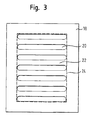
- a schematic plan view of such a perforated passage according to the prior art is shown in Fig. 3, with slots 20 and webs 22, is shown.
- the webs 22 are also referred to as metal bridges.
- the total area of the perforated area is bounded by a line 24.
- Fig. 4 which shows a schematic Schitt representation through the passage plate 18 of FIG. 3, the open air passage surface, which is bounded by the webs 22, schematically indicated by arrows 26.
- Fig. 2 shows a housing 30 for any electrical or electronic device having a side wall 32, a rear wall 34 and a top wall 36 according to the invention.
- a perforated passage plate 38 for ventilation of the interior of the housing.
- the passage plate 38 has slots 40 which are bounded by outwardly bent webs 42.
- Fig. 5 shows a schematic sectional view through the passage plate 38 with a curved web 42, wherein arrows 46 schematically indicate the effective area of the bounded by the curved webs 42 through openings.
- This comparative measurement shows the flow resistance of the remaining system, including the pressure drop through the housing and the rear passage hole due to friction and the like. From an overall view of the measurements, an increase in the flow rate of approximately 6% results when, instead of the flat standard perforation, the perforated passage design according to the invention is used according to the specifications under 2. above.
- a more detailed analysis of the flow or pressure conditions at the perforated surfaces by means of a flow simulation (CFD) shows that at the same pressure loss of 15 Pa an increased throughput of about 12% or at the same throughput of 0.09 m 3 / s sets a 26% reduction in pressure drop when used instead the standard perforation, the perforation according to the shown embodiment of the invention is used. By an even greater bending and elongation of the webs 42 between the passage openings of this factor can be further increased.
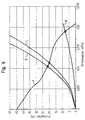
- FIG. 6 is a graph of flow curves in a fan-cooled device that has been modified in accordance with the embodiments described above.
- the curve indicated by the letter A in Fig. 6 represents the pressure (P) flow rate (Q) characteristic of the fan used in the described embodiment.
- This characteristic A determines the operating points of the system. If the fan is operated in a housing with the back removed, characteristic B applies; when the fan is operated in a housing having a passage opening according to the invention, characteristic C is valid; and when the fan is operated in a housing having a passage with a standard perforation according to the prior art, characteristic curve D is valid.
- the illustration of Fig. 6 shows that the inventive design of the passage opening a higher flow rate at a lower pressure drop below Using the same fan is achieved.
Landscapes
- Engineering & Computer Science (AREA)
- Microelectronics & Electronic Packaging (AREA)
- Cooling Or The Like Of Electrical Apparatus (AREA)
Applications Claiming Priority (3)
| Application Number | Priority Date | Filing Date | Title |
|---|---|---|---|
| DE10155810A DE10155810B4 (de) | 2001-11-14 | 2001-11-14 | Gehäusekomponente für eine zu belüftende Einrichtung |
| DE10155810 | 2001-11-14 | ||
| PCT/EP2002/012439 WO2003043395A1 (de) | 2001-11-14 | 2002-11-07 | Gehäusekomponente für eine zu belüftende einrichtung |
Publications (2)
| Publication Number | Publication Date |
|---|---|
| EP1444875A1 EP1444875A1 (de) | 2004-08-11 |
| EP1444875B1 true EP1444875B1 (de) | 2006-01-18 |
Family
ID=7705659
Family Applications (1)
| Application Number | Title | Priority Date | Filing Date |
|---|---|---|---|
| EP02779534A Expired - Lifetime EP1444875B1 (de) | 2001-11-14 | 2002-11-07 | Gehäusekomponente für eine zu belüftende einrichtung |
Country Status (8)
| Country | Link |
|---|---|
| US (1) | US20050052845A1 (enExample) |
| EP (1) | EP1444875B1 (enExample) |
| JP (1) | JP2005510069A (enExample) |
| CN (1) | CN1270589C (enExample) |
| DE (1) | DE10155810B4 (enExample) |
| NO (1) | NO20042443L (enExample) |
| TW (1) | TW563391B (enExample) |
| WO (1) | WO2003043395A1 (enExample) |
Families Citing this family (5)
| Publication number | Priority date | Publication date | Assignee | Title |
|---|---|---|---|---|
| US7595976B2 (en) * | 2004-10-21 | 2009-09-29 | Mitsubishi Denki Kabushiki Kaisha | Outdoor apparatus |
| JP2007027319A (ja) * | 2005-07-14 | 2007-02-01 | Sony Corp | メッシュ材及び電子機器 |
| CN101883479A (zh) * | 2009-05-06 | 2010-11-10 | 鸿富锦精密工业(深圳)有限公司 | 电子装置壳体 |
| US9175872B2 (en) * | 2011-10-06 | 2015-11-03 | Lennox Industries Inc. | ERV global pressure demand control ventilation mode |
| TWI594688B (zh) * | 2014-11-14 | 2017-08-01 | 廣達電腦股份有限公司 | 散熱模組 |
Family Cites Families (14)
| Publication number | Priority date | Publication date | Assignee | Title |
|---|---|---|---|---|
| DE3214823C2 (de) * | 1982-04-21 | 1984-02-02 | Nixdorf Computer Ag, 4790 Paderborn | Lüftungsgitter für zur Aufnahme von elektronischen Baugruppen bestimmte Gerätegehäuse |
| US4949934A (en) * | 1989-04-05 | 1990-08-21 | Zenith Data Systems Corporation | Computer stand |
| US5458408A (en) * | 1993-04-06 | 1995-10-17 | Hewlett-Packard Corporation | Enclosure with spill-resistant ventilation for electronic equipment |
| US5460571A (en) * | 1994-10-31 | 1995-10-24 | Kato; Junichi | Electro-magnetically shielded ventilation system |
| US5744213A (en) * | 1995-08-25 | 1998-04-28 | Soltech. Inc. | Enclosure panel with herringbone aperture pattern |
| US5608609A (en) * | 1995-09-11 | 1997-03-04 | Lucent Technologies Inc. | Outdoor cabinet for electronic equipment |
| US5762550A (en) * | 1996-08-21 | 1998-06-09 | Toshiba America Information Systems, Inc. | Heat transfer system for electronic enclosures |
| US6018125A (en) * | 1996-11-15 | 2000-01-25 | Collins; Pat Eliot | High frequency EMI shield with air flow for electronic device enclosure |
| US6137677A (en) * | 1997-06-13 | 2000-10-24 | Compaq Computer Corporation | Ergonomic controls for a personal computer CPU |
| US6336691B1 (en) * | 1999-05-05 | 2002-01-08 | Plug-In Storage Systems, Inc. | Storage cabinet for electronic devices |
| US6480398B1 (en) * | 2000-01-05 | 2002-11-12 | Compaq Computer Corporation | CPU easy access panels |
| DE20010352U1 (de) * | 2000-06-09 | 2000-09-28 | Wang, Joseph, Chilung | Chassis-Anordnung eines Netzteils |
| US6616252B2 (en) * | 2001-07-30 | 2003-09-09 | Hewlett-Packard Development Company, L.P. | Permanently attached rackmount handles and spacing brackets |
| TW534355U (en) * | 2001-10-26 | 2003-05-21 | Hon Hai Prec Ind Co Ltd | Computer housing |
-
2001
- 2001-11-14 DE DE10155810A patent/DE10155810B4/de not_active Expired - Fee Related
-
2002
- 2002-10-25 TW TW091125082A patent/TW563391B/zh active
- 2002-11-07 EP EP02779534A patent/EP1444875B1/de not_active Expired - Lifetime
- 2002-11-07 US US10/495,380 patent/US20050052845A1/en not_active Abandoned
- 2002-11-07 WO PCT/EP2002/012439 patent/WO2003043395A1/de not_active Ceased
- 2002-11-07 JP JP2003545088A patent/JP2005510069A/ja not_active Withdrawn
- 2002-11-07 CN CN02822435.3A patent/CN1270589C/zh not_active Expired - Fee Related
-
2004
- 2004-06-11 NO NO20042443A patent/NO20042443L/no unknown
Also Published As
| Publication number | Publication date |
|---|---|
| JP2005510069A (ja) | 2005-04-14 |
| WO2003043395A1 (de) | 2003-05-22 |
| NO20042443L (no) | 2004-08-03 |
| TW563391B (en) | 2003-11-21 |
| CN1586097A (zh) | 2005-02-23 |
| EP1444875A1 (de) | 2004-08-11 |
| DE10155810A1 (de) | 2003-05-22 |
| DE10155810B4 (de) | 2004-02-12 |
| US20050052845A1 (en) | 2005-03-10 |
| CN1270589C (zh) | 2006-08-16 |
Similar Documents
| Publication | Publication Date | Title |
|---|---|---|
| DE3039681C2 (de) | Elektromagnetische Abschirmvorrichtung für Elektronikschränke | |
| WO2000074459A1 (de) | Filterlüfter, der in einer ausnehmung einer wand montierbar ist | |
| EP0895448A2 (de) | Anordnung zur Belüftung von elektrischen und elektronischen Geräten und Baugruppen | |
| EP2683230B1 (de) | Kastengehäuse | |
| DE19830791C2 (de) | Mit elektromagnetischen Wellen arbeitendes Radargerät | |
| EP1444875B1 (de) | Gehäusekomponente für eine zu belüftende einrichtung | |
| DE20100235U1 (de) | Paralleler Ventilator | |
| EP0313131A2 (de) | Aufnahmevorrichtung mit geschirmten Leiterplatten | |
| EP2982014B1 (de) | Erreichung einer schutzart für elektrische und elektronische geräte, insbesondere für schaltschränke | |
| DE102020133191A1 (de) | Verbinderträger und Rangierfeldsystem, bei dem der Verbinderträger verwendbar ist | |
| DE3940842A1 (de) | Bediengeraet fuer nachrichtentechnische geraete | |
| DE19742373C2 (de) | Computergehäuse | |
| EP1370125A1 (de) | Luftdurchtrittseinrichtung | |
| DE102018106823A1 (de) | Umgebungstestvorrichtung und Wärmebehandlungsvorrichtung | |
| DE102011015547B3 (de) | Luftleithaube für auf einer Leiterplatte angeordnete elektrische Komponenten und Verfahren zum Herstellen einer solchen | |
| AT328U1 (de) | Mechanische verbindung fuer leiterplatten zum aufbau raeumlicher gebilde aus flaechigem leiterplattenabfall | |
| DE102005063024A1 (de) | Luftleithaube | |
| LU502656B1 (de) | Gehäuse für eine elektrische Schaltung und zugehöriges Herstellungsverfahren | |
| DE10008019C2 (de) | Anordnung zur Belüftung von elektrischen und elektronischen Baugruppen | |
| DE68920988T2 (de) | Schutzmittel für Ein- und Auslass der Ventilationsluft in elektrischen Drehmaschinen. | |
| DE2503199C3 (de) | Geräte-Trägerplatte | |
| BE1030623B1 (de) | Vorrichtung und Verfahren für Gehäuse elektrischer Geräte | |
| EP0132780A1 (de) | Querstromlüfter mit in den Randzonen erhöhter Luftaustrittsgeschwindigkeit | |
| DE102024114444A1 (de) | Isolierungsvorrichtung, stator, elektrische maschine | |
| DE20308482U1 (de) | Luftdurchtrittseinrichtung |
Legal Events
| Date | Code | Title | Description |
|---|---|---|---|
| PUAI | Public reference made under article 153(3) epc to a published international application that has entered the european phase |
Free format text: ORIGINAL CODE: 0009012 |
|
| 17P | Request for examination filed |
Effective date: 20040510 |
|
| AK | Designated contracting states |
Kind code of ref document: A1 Designated state(s): AT BE BG CH CY CZ DE DK EE ES FI FR GB GR IE IT LI LU MC NL PT SE SK TR |
|
| AX | Request for extension of the european patent |
Extension state: AL LT LV MK RO SI |
|
| GRAP | Despatch of communication of intention to grant a patent |
Free format text: ORIGINAL CODE: EPIDOSNIGR1 |
|
| GRAS | Grant fee paid |
Free format text: ORIGINAL CODE: EPIDOSNIGR3 |
|
| REG | Reference to a national code |
Ref country code: DE Ref legal event code: 8566 |
|
| GRAA | (expected) grant |
Free format text: ORIGINAL CODE: 0009210 |
|
| AK | Designated contracting states |
Kind code of ref document: B1 Designated state(s): FI GB IT |
|
| PG25 | Lapsed in a contracting state [announced via postgrant information from national office to epo] |
Ref country code: IT Free format text: LAPSE BECAUSE OF FAILURE TO SUBMIT A TRANSLATION OF THE DESCRIPTION OR TO PAY THE FEE WITHIN THE PRESCRIBED TIME-LIMIT;WARNING: LAPSES OF ITALIAN PATENTS WITH EFFECTIVE DATE BEFORE 2007 MAY HAVE OCCURRED AT ANY TIME BEFORE 2007. THE CORRECT EFFECTIVE DATE MAY BE DIFFERENT FROM THE ONE RECORDED. Effective date: 20060118 |
|
| REG | Reference to a national code |
Ref country code: GB Ref legal event code: FG4D Free format text: NOT ENGLISH |
|
| GBT | Gb: translation of ep patent filed (gb section 77(6)(a)/1977) |
Effective date: 20060118 |
|
| PG25 | Lapsed in a contracting state [announced via postgrant information from national office to epo] |
Ref country code: FI Free format text: LAPSE BECAUSE OF NON-PAYMENT OF DUE FEES Effective date: 20061107 |
|
| PLBE | No opposition filed within time limit |
Free format text: ORIGINAL CODE: 0009261 |
|
| STAA | Information on the status of an ep patent application or granted ep patent |
Free format text: STATUS: NO OPPOSITION FILED WITHIN TIME LIMIT |
|
| 26N | No opposition filed |
Effective date: 20061019 |
|
| GBPC | Gb: european patent ceased through non-payment of renewal fee |
Effective date: 20061107 |
|
| PG25 | Lapsed in a contracting state [announced via postgrant information from national office to epo] |
Ref country code: GB Free format text: LAPSE BECAUSE OF NON-PAYMENT OF DUE FEES Effective date: 20061107 |
|
| PGFP | Annual fee paid to national office [announced via postgrant information from national office to epo] |
Ref country code: IT Payment date: 20091114 Year of fee payment: 8 |
|
| PG25 | Lapsed in a contracting state [announced via postgrant information from national office to epo] |
Ref country code: IT Free format text: LAPSE BECAUSE OF NON-PAYMENT OF DUE FEES Effective date: 20101107 |