EP1444432B1 - A stirling engine assembly - Google Patents
A stirling engine assembly Download PDFInfo
- Publication number
- EP1444432B1 EP1444432B1 EP02777521A EP02777521A EP1444432B1 EP 1444432 B1 EP1444432 B1 EP 1444432B1 EP 02777521 A EP02777521 A EP 02777521A EP 02777521 A EP02777521 A EP 02777521A EP 1444432 B1 EP1444432 B1 EP 1444432B1
- Authority
- EP
- European Patent Office
- Prior art keywords
- engine
- assembly according
- resilient members
- axis
- mass
- Prior art date
- Legal status (The legal status is an assumption and is not a legal conclusion. Google has not performed a legal analysis and makes no representation as to the accuracy of the status listed.)
- Expired - Lifetime
Links
- 238000010521 absorption reaction Methods 0.000 claims description 16
- 239000006096 absorbing agent Substances 0.000 description 19
- 230000006835 compression Effects 0.000 description 9
- 238000007906 compression Methods 0.000 description 9
- 238000010586 diagram Methods 0.000 description 5
- 239000000725 suspension Substances 0.000 description 5
- 238000013016 damping Methods 0.000 description 4
- 230000002238 attenuated effect Effects 0.000 description 2
- 230000005540 biological transmission Effects 0.000 description 2
- 230000005284 excitation Effects 0.000 description 2
- 238000002955 isolation Methods 0.000 description 2
- 230000000712 assembly Effects 0.000 description 1
- 238000000429 assembly Methods 0.000 description 1
- 238000002485 combustion reaction Methods 0.000 description 1
- 239000000463 material Substances 0.000 description 1
- 230000000284 resting effect Effects 0.000 description 1
- 238000007789 sealing Methods 0.000 description 1
Images



Classifications
-
- F—MECHANICAL ENGINEERING; LIGHTING; HEATING; WEAPONS; BLASTING
- F16—ENGINEERING ELEMENTS AND UNITS; GENERAL MEASURES FOR PRODUCING AND MAINTAINING EFFECTIVE FUNCTIONING OF MACHINES OR INSTALLATIONS; THERMAL INSULATION IN GENERAL
- F16F—SPRINGS; SHOCK-ABSORBERS; MEANS FOR DAMPING VIBRATION
- F16F15/00—Suppression of vibrations in systems; Means or arrangements for avoiding or reducing out-of-balance forces, e.g. due to motion
- F16F15/02—Suppression of vibrations of non-rotating, e.g. reciprocating systems; Suppression of vibrations of rotating systems by use of members not moving with the rotating systems
- F16F15/04—Suppression of vibrations of non-rotating, e.g. reciprocating systems; Suppression of vibrations of rotating systems by use of members not moving with the rotating systems using elastic means
- F16F15/08—Suppression of vibrations of non-rotating, e.g. reciprocating systems; Suppression of vibrations of rotating systems by use of members not moving with the rotating systems using elastic means with rubber springs ; with springs made of rubber and metal
- F16F15/085—Use of both rubber and metal springs
-
- F—MECHANICAL ENGINEERING; LIGHTING; HEATING; WEAPONS; BLASTING
- F02—COMBUSTION ENGINES; HOT-GAS OR COMBUSTION-PRODUCT ENGINE PLANTS
- F02G—HOT GAS OR COMBUSTION-PRODUCT POSITIVE-DISPLACEMENT ENGINE PLANTS; USE OF WASTE HEAT OF COMBUSTION ENGINES; NOT OTHERWISE PROVIDED FOR
- F02G1/00—Hot gas positive-displacement engine plants
- F02G1/04—Hot gas positive-displacement engine plants of closed-cycle type
- F02G1/043—Hot gas positive-displacement engine plants of closed-cycle type the engine being operated by expansion and contraction of a mass of working gas which is heated and cooled in one of a plurality of constantly communicating expansible chambers, e.g. Stirling cycle type engines
- F02G1/0435—Hot gas positive-displacement engine plants of closed-cycle type the engine being operated by expansion and contraction of a mass of working gas which is heated and cooled in one of a plurality of constantly communicating expansible chambers, e.g. Stirling cycle type engines the engine being of the free piston type
-
- F—MECHANICAL ENGINEERING; LIGHTING; HEATING; WEAPONS; BLASTING
- F16—ENGINEERING ELEMENTS AND UNITS; GENERAL MEASURES FOR PRODUCING AND MAINTAINING EFFECTIVE FUNCTIONING OF MACHINES OR INSTALLATIONS; THERMAL INSULATION IN GENERAL
- F16F—SPRINGS; SHOCK-ABSORBERS; MEANS FOR DAMPING VIBRATION
- F16F15/00—Suppression of vibrations in systems; Means or arrangements for avoiding or reducing out-of-balance forces, e.g. due to motion
- F16F15/02—Suppression of vibrations of non-rotating, e.g. reciprocating systems; Suppression of vibrations of rotating systems by use of members not moving with the rotating systems
- F16F15/04—Suppression of vibrations of non-rotating, e.g. reciprocating systems; Suppression of vibrations of rotating systems by use of members not moving with the rotating systems using elastic means
- F16F15/046—Suppression of vibrations of non-rotating, e.g. reciprocating systems; Suppression of vibrations of rotating systems by use of members not moving with the rotating systems using elastic means using combinations of springs of different kinds
-
- F—MECHANICAL ENGINEERING; LIGHTING; HEATING; WEAPONS; BLASTING
- F16—ENGINEERING ELEMENTS AND UNITS; GENERAL MEASURES FOR PRODUCING AND MAINTAINING EFFECTIVE FUNCTIONING OF MACHINES OR INSTALLATIONS; THERMAL INSULATION IN GENERAL
- F16F—SPRINGS; SHOCK-ABSORBERS; MEANS FOR DAMPING VIBRATION
- F16F7/00—Vibration-dampers; Shock-absorbers
- F16F7/10—Vibration-dampers; Shock-absorbers using inertia effect
- F16F7/104—Vibration-dampers; Shock-absorbers using inertia effect the inertia member being resiliently mounted
-
- F—MECHANICAL ENGINEERING; LIGHTING; HEATING; WEAPONS; BLASTING
- F02—COMBUSTION ENGINES; HOT-GAS OR COMBUSTION-PRODUCT ENGINE PLANTS
- F02G—HOT GAS OR COMBUSTION-PRODUCT POSITIVE-DISPLACEMENT ENGINE PLANTS; USE OF WASTE HEAT OF COMBUSTION ENGINES; NOT OTHERWISE PROVIDED FOR
- F02G2243/00—Stirling type engines having closed regenerative thermodynamic cycles with flow controlled by volume changes
- F02G2243/02—Stirling type engines having closed regenerative thermodynamic cycles with flow controlled by volume changes having pistons and displacers in the same cylinder
- F02G2243/20—Stirling type engines having closed regenerative thermodynamic cycles with flow controlled by volume changes having pistons and displacers in the same cylinder each having a single free piston, e.g. "Beale engines"
Definitions
- the present invention relates to a Stirling engine assembly.
- the invention relates to an assembly suitable for use in a domestic combined heat and power (DCHP) unit.
- DCHP domestic combined heat and power
- Such a unit is intended to be used in a domestic environment in place of a conventional boiler. In such a situation, it is vital that the noise and vibration is kept to a very low level so as to be acceptable to a consumer.
- a Stirling engine assembly comprises a Stirling engine, a mounting frame on which the engine is mounted so that the axis along which reciprocating components of the engine reciprocate is vertical, in use, the engine being hung from the mounting frame by a plurality of tension springs.
- the springs used can be low stiffness, high deflection springs.
- the conflict in the prior art between the need for stable support and the need for a low stiffness mounting system has been removed.
- the springs from which the engine is suspended are particularly suitable for preventing transmission of low frequency vibrations.
- a rubber pad is preferably connected in series with each spring.
- the pad may be between the spring and the engine, between the spring and the mounting frame, or both. These rubber pads are particularly useful for attenuating high frequency vibrations.
- the mounting frame is preferably connected to the lower half of the engine. This allows longer springs to be used than would be required if the mounting frame were to be connected to the upper part of the engine.
- a housing for the burner located above and around the upper dome of the engine, may incorporate a flexible annular guide between its inner lower face and the engine.
- This could be, for example, an 'O' ring, of a material suitable for use in this vibrating, high temperature environment. This would allow some lateral movement, so that the engine vibration would not cause damage, and prevent the transmission of unwanted forces, but would also maintain the stability of the engine.
- Alternative sealing arrangements able to withstand the high temperature, high vibration environment could also be used.
- the springs preferably have a free length of 100 - 150mm and a total stiffness of between 0.6 and 0.9 kg/mm.
- the length of the springs when the engine is hung from them is equal to the length of the engine body ⁇ 20%.
- a vibration absorption mass is suspended from the engine on at least one resilient member and is arranged to provide an anti-phase force to the engine.
- the vibration absorption mass may be either suspended beneath the engine or may be an annular mass suspended so as to surround the engine. This latter arrangement can be advantageous to provide a Stirling engine with a shorter overall height.
- the pitching frequency tends to coincide with the vertical frequency due to a combination of the inertia of the mass around the horizontal axes and the rotational stiffness of the spring system about the same axes.
- the resilient members are preferably arranged asymmetrically about the main axis of the annular member. This can be done, for example, by providing resilient members of different stiffnesses. These are preferably arranged symmetrically on opposite sides of a first axis perpendicular to the main axis, and more preferably also arranged symmetrically on opposite sides of a second axis perpendicular to the main axis and the first axis.
- the asymmetrical arrangement may be provided by grouping the resilient members close to a first axis perpendicular to the main axis.
- the resilient members are preferably arranged symmetrically on opposite sides of the first axis.
- the mass of the vibration absorption mass may be reduced adjacent to the horizontal axis of highest rotational stiffness as compared to the rest of the vibration absorption mass.
- This asymmetric annular absorber mass forms an independent aspect of the invention which is broadly defined as a Stirling engine assembly comprising a Stirling engine, a mounting frame on which the engine is mounted so that the axis along which the reciprocating components reciprocate is vertical, in use, wherein an annular absorption mass surrounds the Stirling engine and is suspended from the engine on a plurality of resilient members, to provide an anti-phase force to the engine, the resilient members being arranged asymmetrically about the main axis of the annular member.
- This arrangement can be used when the engine is hung from springs according to the first aspect of the invention, or is suspended from some other resilient mounting.
- the Stirling engine assembly comprises a Stirling engine 1 that is well known in the art.
- the Stirling engine has displacer and power pistons, both of which are arranged to reciprocate in a vertical direction. This produces a net vertical vibration of the Stirling engine 1 itself.
- a vibration absorber mass 2 is supported by a number of compression springs 3 both above and below the absorber mass 2.
- This arrangement is housed in a housing 4 which is rigidly fixed to the bottom of the Stirling engine 1.
- the mass 2 and springs 3 are tuned so that when the Stirling engine 1 is operating at its normal operating frequency, the absorber mass 2 vibrates as closely as possible in anti-phase to the Stirling engine 1. As a result of this, the overall vibration of the Stirling engine 1 and housing 4 is greatly reduced.
- the current arrangement incorporates eight compression springs 3 above and eight compression springs 3 below the 10.5 kg ( ⁇ 10%) isolator mass 2. These springs have, for example, a free length of 67mm, and a stiffness of 66.25 N/mm ( ⁇ 10%).
- the absorber is tuned to absorb vibrations of frequency, 48 Hz to 52 Hz, (minimum vibration at 50.25 Hz).
- the above described assembly of Stirling engine 1 and housing 4 is mounted to a mounting frame 5 which surrounds the head of the engine as shown in Fig. 1 .
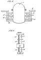
- the engine 1 and housing 4 are suspended from the mounting frame by a plurality of mounting assemblies spaced around the Stirling engine, one of which is shown in Fig. 2A and 2B .
- Each mounting assembly comprises a pair of tension springs 6 provided at their upper ends with a hook 7 for attachment to the mounting frame 5.
- a second hook 8 attaches the lower end of each spring to a frame 9.
- the thickness of the spring wire is chosen to be sufficient to support the weight of the engine 1 and absorber mass 2, which could be between 40 and 80 kg, but is typically 60 kg. In this case the wire diameter is typically 2.4 mm.
- the springs need to be as long as possible, with the mounting points as far apart as the design will permit.
- the upper mounting frame 5 is located immediately below the engine burner housing, and a lower engine mounting ring 12 is located on the lower engine flange.
- the extended spring length is then approximately equal to the length of the engine body (typically 190mm) which excludes a cooler 13, heat transfer head 14 and back end dome 15 (as shown in Fig. 1 ).
- care must be taken to ensure that the spring natural (surge) frequency does not coincide with the engine running frequency, or its harmonics, which would result in unacceptable resonance.
- the free length of the springs is preferably 100 to 150 mm (typically 127 mm).
- the total spring stiffness is between 0.6 and 0.9 kg/mm (typically 0.75 kg/mm), giving each spring a stiffness (spring rate), in this configuration, of typically 0.09 kg/mm.
- each frame 9 Seated in each frame 9 is a rubber element 10.
- This rubber element 10 bears a mounting bolt 11 by virtue of which the mounting assembly attaches to a mounting ring 12 on the Stirling engine 1.
- any vibrations in the Stirling engine 1 are transmitted via the bolt 11, to the rubber element 10, into the frame 9 and then through the springs 6 to the mounting frame 5.
- a rubber element may be provided at the top of each spring.
- the stiffness per rubber element 10 based on four sets of springs is, for example, 110 N/mm.
- the rubber elements are designed to remove the high frequency content and hence the quoted stiffness is adequate and the strain is kept within sensible levels bearing in mind the reduction in performance of the rubber at elevated temperatures.
- the higher frequency vibrations tend to be attenuated by the rubber element 10, while the lower frequency vibrations are attenuated by the springs 6, such that the vibrations experienced by the mounting frame 5 is negligible, and is within the acceptable limits for the DCHP unit.
- FIG. 3 An alternative assembly to that shown in Fig. 1 is shown in Fig. 3 .
- the housing 4' is mounted so as to surround the Stirling engine 1, rather than being suspended beneath the engine 1 as in Fig. 1 .
- the absorber mass 2' is annular and surrounds the Stirling engine.
- This embodiment requires that the mounting ring 12 has a considerably larger diameter than that of Fig. 1 .
- the overall height of the apparatus is reduced, and hence this design is useful when elevational space is limited.
- the arrangement is as shown in Fig. 1 and the same reference numerals have been used to designate the same components.
- Fig. 4 The dynamics of the assembly are shown in Fig. 4 .
- the elements are as follows:
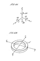
- Figs. 5A and 5B define an axis system for the annular mass.
- the X, Y and Z axes are mutually orthogonal, with the X and Y axes being horizontal axes in the plane of the annular mass intersecting at the centre of the annular mass, and the Z axis being the vertical axis extending from the centre of the absorber mass 2'.
- the natural excitation frequency causes vertical reciprocation in the direction of arrow 20.
- the pitching frequency tends to coincide with the vertical frequency causing pitching about the X and Y axes as shown by arrows 21 and 22 respectively.
- the annular absorber mass also rotates about the Z axis as shown with arrow 23.
- an asymmetrical arrangement of springs, or an asymmetry of absorber mass inertia is proposed.
- Fig. 6 The first example of this is shown in Fig. 6 .
- This arrangement is generally suitable for the situation where the rotational inertias of the absorber mass about the X and Y axes are equal.
- the absorber mass 2' has a uniform cross-section and a uniform mass.
- the springs As shown in Fig. 6 , where four of the springs have a stiffness K, while the remaining four have a stiffness of 0.5K it should be noted that this provides a stiffness variation around the periphery of the mass, but not across the mass as the stiffness of the springs is symmetrical on opposite sides of the X and Y axes.
- the spring stiffness pattern is replicated above and below the absorber mass.
- both the spring stiffness and the absorber mass rotating inertia are asymmetric.
- FIG. 7 A second arrangement is shown in Fig. 7 which is particularly suitable when the rotational inertias of the absorber annulus are different about the X and Y axes.
- eight springs of equal stiffness K' are provided but are grouped by the axis of highest inertia (X) consistent with the need to maintain sufficient stability during operation.
- an annular mass 2" is provided which essentially has a pair of cutout portions 25 at opposite sides of annular mass 2" and the eight springs are arranged to be attached to mounting points 26 above and below each cutout portion.
Landscapes
- Engineering & Computer Science (AREA)
- General Engineering & Computer Science (AREA)
- Mechanical Engineering (AREA)
- Physics & Mathematics (AREA)
- Acoustics & Sound (AREA)
- Aviation & Aerospace Engineering (AREA)
- Chemical & Material Sciences (AREA)
- Combustion & Propulsion (AREA)
- Vibration Prevention Devices (AREA)
Description
- The present invention relates to a Stirling engine assembly. In particular, the invention relates to an assembly suitable for use in a domestic combined heat and power (DCHP) unit.
- Such a unit is intended to be used in a domestic environment in place of a conventional boiler. In such a situation, it is vital that the noise and vibration is kept to a very low level so as to be acceptable to a consumer.
- The usual practice is to support an engine by mounting it on springs which isolate the vibration produced during normal engine operation. An example of a Stirling engine having such an arrangement is
US 4,400,941 . To maximise the degree of isolation, a low stiffness mounting system is required. However, the implementation of this with compression springs can lead to instability. - According to the present invention, a Stirling engine assembly comprises a Stirling engine, a mounting frame on which the engine is mounted so that the axis along which reciprocating components of the engine reciprocate is vertical, in use, the engine being hung from the mounting frame by a plurality of tension springs.
- By hanging the Stirling engine from springs, rather than resting it on the springs, the springs used can be low stiffness, high deflection springs. Thus, the conflict in the prior art between the need for stable support and the need for a low stiffness mounting system has been removed.
- The springs from which the engine is suspended are particularly suitable for preventing transmission of low frequency vibrations. In order to improve damping across a larger range of frequencies, a rubber pad is preferably connected in series with each spring. The pad may be between the spring and the engine, between the spring and the mounting frame, or both. These rubber pads are particularly useful for attenuating high frequency vibrations.
- The mounting frame is preferably connected to the lower half of the engine. This allows longer springs to be used than would be required if the mounting frame were to be connected to the upper part of the engine.
- In order to provide additional radial stability for the Stirling engine within the surrounding suspension arrangement, and to provide a suitable seal for the combustion area, a housing for the burner, located above and around the upper dome of the engine, may incorporate a flexible annular guide between its inner lower face and the engine. This could be, for example, an 'O' ring, of a material suitable for use in this vibrating, high temperature environment. This would allow some lateral movement, so that the engine vibration would not cause damage, and prevent the transmission of unwanted forces, but would also maintain the stability of the engine. Alternative sealing arrangements, able to withstand the high temperature, high vibration environment could also be used.
- The springs preferably have a free length of 100 - 150mm and a total stiffness of between 0.6 and 0.9 kg/mm. The length of the springs when the engine is hung from them is equal to the length of the engine body ± 20%.
- The above described arrangement is a particularly advantageous suspension arrangement for the Stirling engine. However, further improvements in the design can be achieved by providing a vibration absorption arrangement to minimise the vibration of the engine, and hence reduce the burden on the suspension arrangement. Therefore, preferably, a vibration absorption mass is suspended from the engine on at least one resilient member and is arranged to provide an anti-phase force to the engine. The vibration absorption mass may be either suspended beneath the engine or may be an annular mass suspended so as to surround the engine. This latter arrangement can be advantageous to provide a Stirling engine with a shorter overall height.
- In the case of a symmetrical annular vibration absorption mass, the pitching frequency tends to coincide with the vertical frequency due to a combination of the inertia of the mass around the horizontal axes and the rotational stiffness of the spring system about the same axes.
- The degree of pitching is linked to the lack of diametric stiffness symmetry, the possible offset of the absorber mass from the spring stiffness centre, and the closeness of the excitation frequency to the vertical tuned frequency and the pitching frequencies. Therefore, the resilient members are preferably arranged asymmetrically about the main axis of the annular member. This can be done, for example, by providing resilient members of different stiffnesses. These are preferably arranged symmetrically on opposite sides of a first axis perpendicular to the main axis, and more preferably also arranged symmetrically on opposite sides of a second axis perpendicular to the main axis and the first axis.
- Alternatively, the asymmetrical arrangement may be provided by grouping the resilient members close to a first axis perpendicular to the main axis. With this arrangement, the resilient members are preferably arranged symmetrically on opposite sides of the first axis.
- In either case, the mass of the vibration absorption mass may be reduced adjacent to the horizontal axis of highest rotational stiffness as compared to the rest of the vibration absorption mass.
- This asymmetric annular absorber mass forms an independent aspect of the invention which is broadly defined as a Stirling engine assembly comprising a Stirling engine, a mounting frame on which the engine is mounted so that the axis along which the reciprocating components reciprocate is vertical, in use, wherein an annular absorption mass surrounds the Stirling engine and is suspended from the engine on a plurality of resilient members, to provide an anti-phase force to the engine, the resilient members being arranged asymmetrically about the main axis of the annular member.
- This arrangement can be used when the engine is hung from springs according to the first aspect of the invention, or is suspended from some other resilient mounting.
- An example of a Stirling engine assembly in accordance with the present invention will now be described with reference to the accompanying drawings, in which:
-
Fig. 1 is a schematic cross-section of the assembly; -
Fig. 2A is a front elevation of part of the mounting assembly including two springs; -
Fig. 2B is a side elevation of the arrangement shown inFig. 2A ; -
Fig, 3 is a schematic cross-section of an alternative assembly to that shown inFig. 1 ; -
Fig. 4 is a schematic diagram of the dynamics of the suspension arrangement; -
Fig. 5A is a diagram showing the various modes of vibration of the annular absorption mass; -
Fig. 5B is a diagram showing the axes of the absorption mass; -
Fig. 6 is a schematic diagram showing the first spring arrangement; -
Fig. 7 is a schematic diagram showing a second spring arrangement; and -
Fig. 8 is a perspective view of the annular mass suitable for use in the arrangement ofFig. 7 . - The Stirling engine assembly comprises a Stirling
engine 1 that is well known in the art. The Stirling engine has displacer and power pistons, both of which are arranged to reciprocate in a vertical direction. This produces a net vertical vibration of the Stirlingengine 1 itself. - In order to reduce this vibration, a vibration absorber mass 2 is supported by a number of compression springs 3 both above and below the absorber mass 2. This arrangement is housed in a
housing 4 which is rigidly fixed to the bottom of the Stirlingengine 1. The mass 2 and springs 3 are tuned so that when the Stirlingengine 1 is operating at its normal operating frequency, the absorber mass 2 vibrates as closely as possible in anti-phase to the Stirlingengine 1. As a result of this, the overall vibration of the Stirlingengine 1 andhousing 4 is greatly reduced. - The current arrangement incorporates eight compression springs 3 above and eight compression springs 3 below the 10.5 kg (±10%) isolator mass 2. These springs have, for example, a free length of 67mm, and a stiffness of 66.25 N/mm (±10%). The absorber is tuned to absorb vibrations of frequency, 48 Hz to 52 Hz, (minimum vibration at 50.25 Hz).
- The above described assembly of Stirling
engine 1 andhousing 4 is mounted to amounting frame 5 which surrounds the head of the engine as shown inFig. 1 . Theengine 1 andhousing 4 are suspended from the mounting frame by a plurality of mounting assemblies spaced around the Stirling engine, one of which is shown inFig. 2A and 2B . Each mounting assembly comprises a pair of tension springs 6 provided at their upper ends with a hook 7 for attachment to the mountingframe 5. A second hook 8 attaches the lower end of each spring to a frame 9. - The thickness of the spring wire is chosen to be sufficient to support the weight of the
engine 1 and absorber mass 2, which could be between 40 and 80 kg, but is typically 60 kg. In this case the wire diameter is typically 2.4 mm. - In order to provide the optimum suspension isolation, reducing low frequency vibration, the springs need to be as long as possible, with the mounting points as far apart as the design will permit. In this case, the
upper mounting frame 5 is located immediately below the engine burner housing, and a lowerengine mounting ring 12 is located on the lower engine flange. The extended spring length is then approximately equal to the length of the engine body (typically 190mm) which excludes a cooler 13, heat transfer head 14 and back end dome 15 (as shown inFig. 1 ). In addition, care must be taken to ensure that the spring natural (surge) frequency does not coincide with the engine running frequency, or its harmonics, which would result in unacceptable resonance. - In the current configuration, with 6 to 12 springs (typically 8), arranged in pairs, located with regular spacing around the engine, the free length of the springs is preferably 100 to 150 mm (typically 127 mm). The total spring stiffness is between 0.6 and 0.9 kg/mm (typically 0.75 kg/mm), giving each spring a stiffness (spring rate), in this configuration, of typically 0.09 kg/mm.
- Seated in each frame 9 is a
rubber element 10. Thisrubber element 10 bears a mounting bolt 11 by virtue of which the mounting assembly attaches to a mountingring 12 on theStirling engine 1. Thus, any vibrations in theStirling engine 1 are transmitted via the bolt 11, to therubber element 10, into the frame 9 and then through the springs 6 to the mountingframe 5. - As an alternative, or in addition to the
rubber element 10 at the bottom of each spring a rubber element may be provided at the top of each spring. - The stiffness per
rubber element 10 based on four sets of springs, is, for example, 110 N/mm. The rubber elements are designed to remove the high frequency content and hence the quoted stiffness is adequate and the strain is kept within sensible levels bearing in mind the reduction in performance of the rubber at elevated temperatures. - The higher frequency vibrations tend to be attenuated by the
rubber element 10, while the lower frequency vibrations are attenuated by the springs 6, such that the vibrations experienced by the mountingframe 5 is negligible, and is within the acceptable limits for the DCHP unit. - An alternative assembly to that shown in
Fig. 1 is shown inFig. 3 . In this arrangement, the housing 4' is mounted so as to surround theStirling engine 1, rather than being suspended beneath theengine 1 as inFig. 1 . In this case, the absorber mass 2' is annular and surrounds the Stirling engine. This embodiment requires that the mountingring 12 has a considerably larger diameter than that ofFig. 1 . However, the overall height of the apparatus is reduced, and hence this design is useful when elevational space is limited. Otherwise, the arrangement is as shown inFig. 1 and the same reference numerals have been used to designate the same components. - The dynamics of the assembly are shown in
Fig. 4 . In this figure the elements are as follows: - m1 - main engine mass,
- m2 - absorber mass (2),
- k1 - tension spring (6) stiffness x no. of tension springs,
- c1 - damping value associated with tension spring arrangement,
- k2 - compression stiffness of rubber element (10) x no. of rubber elements,
- c2 - damping value associated with compression rubber element,
- k3 - compression spring (3) stiffness x no. of compression springs (typically 16),
- c3 - damping value associated with compression springs and air movements around absorber mass.
- Modified versions of the annular absorber mass of
Fig. 3 are described with reference toFigs. 5 to 8 . -
Figs. 5A and 5B define an axis system for the annular mass. The X, Y and Z axes are mutually orthogonal, with the X and Y axes being horizontal axes in the plane of the annular mass intersecting at the centre of the annular mass, and the Z axis being the vertical axis extending from the centre of the absorber mass 2'. The natural excitation frequency causes vertical reciprocation in the direction ofarrow 20. However, the pitching frequency tends to coincide with the vertical frequency causing pitching about the X and Y axes as shown byarrows 21 and 22 respectively. The annular absorber mass also rotates about the Z axis as shown witharrow 23. In order to reduce the pitching about the X and Y axes, an asymmetrical arrangement of springs, or an asymmetry of absorber mass inertia is proposed. - The first example of this is shown in
Fig. 6 . This arrangement is generally suitable for the situation where the rotational inertias of the absorber mass about the X and Y axes are equal. In this case, the absorber mass 2' has a uniform cross-section and a uniform mass. By arranging the springs as shown inFig. 6 , where four of the springs have a stiffness K, while the remaining four have a stiffness of 0.5K it should be noted that this provides a stiffness variation around the periphery of the mass, but not across the mass as the stiffness of the springs is symmetrical on opposite sides of the X and Y axes. The spring stiffness pattern is replicated above and below the absorber mass. In the second arrangement, both the spring stiffness and the absorber mass rotating inertia are asymmetric. - A second arrangement is shown in
Fig. 7 which is particularly suitable when the rotational inertias of the absorber annulus are different about the X and Y axes. In this case, eight springs of equal stiffness K' are provided but are grouped by the axis of highest inertia (X) consistent with the need to maintain sufficient stability during operation. In this case, an annular mass 2" is provided which essentially has a pair ofcutout portions 25 at opposite sides of annular mass 2" and the eight springs are arranged to be attached to mountingpoints 26 above and below each cutout portion.
Claims (22)
- A Stirling engine assembly comprising a Stirling engine, a mounting frame on which the engine is mounted so that the axis along which the reciprocating components reciprocate is vertical, in use, the engine being hung from the mounting frame by a plurality of tension springs.
- An assembly according to claim 1, wherein a rubber pad is connected in series with each spring.
- An assembly according to claim 1 or claim 2, wherein the springs have a free length of between 100 and 150 mm.
- An assembly according to any one of the preceding claims, wherein the springs have a length, when the Stirling engine is hung from them equal to the length of the engine body ± 20%.
- An assembly according to any one of the preceding claims, wherein the springs have a total stiffness of 0.6-0.9 kg/mm.
- An assembly according to claim 1 or claim 2, wherein the mounting frame is connected to the lower half of the engine.
- An assembly according to any one of the preceding claims, wherein a vibration absorption mass is suspended from the engine on at least one resilient member and is arranged to provide an anti-phase force to the engine.
- An assembly according to claim 7, wherein the vibration absorption mass is annular and surrounds the Stirling engine.
- An assembly according to claim 8, wherein the resilient members are arranged asymmetrically about the main axis of the annular member.
- An assembly according to claim 9, wherein the asymmetrical arrangement is provided by resilient members of different stiffnesses.
- An assembly according to claim 10, wherein the resilient members are arranged symmetrically on opposite sides of first axis perpendicular to the main axis.
- An assembly according to claim 11, wherein the resilient members are also arranged symmetrically on opposite sides of a second axis perpendicular to the main axis and the first axis.
- An assembly according to claim 9, wherein the asymmetrical arrangement is provided by grouping the resilient members close to a first axis perpendicular to the main axis.
- An assembly according to claim 13, wherein the resilient members are arranged symmetrically on opposite sides of the first axis.
- An assembly according any one of claims 9 to 14, wherein the mass of the vibration absorption mass is reduced adjacent to the resilient members as compared to the rest of the vibration absorption mass.
- A Stirling engine assembly comprising a Stirling engine, a mounting frame on which the engine is mounted so that the axis along which the reciprocating components reciprocate is vertical, in use, wherein an annular absorption mass surrounds the Stirling engine and is suspended from the engine on a plurality of resilient members, to provide an anti-phase force to the engine, the resilient members being arranged asymmetrically about the main axis of the annular member.
- An assembly according to claim 16, wherein the asymmetrical arrangement is provided by resilient members of different stiffnesses.
- An assembly according to claim 17, wherein the resilient members are arranged symmetrically on opposite sides of first axis perpendicular to the main axis.
- An assembly according to claim 18, wherein the resilient members are also arranged symmetrically on opposite sides of a second axis perpendicular to the main axis and the first axis.
- An assembly according to claim 16, wherein the asymmetrical arrangement is provided by grouping the resilient members close to a first axis perpendicular to the main axis.
- An assembly according to claim 20, wherein the resilient members are arranged symmetrically on opposite sides of the first axis.
- An assembly according any one of claims 16 to 21, wherein the mass of the vibration absorption mass is reduced adjacent to the resilient members as compared to the rest of the vibration absorption mass.
Applications Claiming Priority (5)
| Application Number | Priority Date | Filing Date | Title |
|---|---|---|---|
| GB0127375 | 2001-11-14 | ||
| GBGB0127375.4A GB0127375D0 (en) | 2001-11-14 | 2001-11-14 | A stirling engine assembly |
| GBGB0203016.1A GB0203016D0 (en) | 2001-11-14 | 2002-02-08 | A stirling engine assembly |
| GB0203016 | 2002-02-08 | ||
| PCT/GB2002/005111 WO2003042566A2 (en) | 2001-11-14 | 2002-11-12 | A stirling engine assembly |
Publications (2)
| Publication Number | Publication Date |
|---|---|
| EP1444432A2 EP1444432A2 (en) | 2004-08-11 |
| EP1444432B1 true EP1444432B1 (en) | 2009-01-28 |
Family
ID=26246768
Family Applications (1)
| Application Number | Title | Priority Date | Filing Date |
|---|---|---|---|
| EP02777521A Expired - Lifetime EP1444432B1 (en) | 2001-11-14 | 2002-11-12 | A stirling engine assembly |
Country Status (11)
| Country | Link |
|---|---|
| US (1) | US6983593B2 (en) |
| EP (1) | EP1444432B1 (en) |
| JP (1) | JP4159469B2 (en) |
| CN (1) | CN100462542C (en) |
| BR (1) | BR0206236A (en) |
| CA (1) | CA2449816A1 (en) |
| MX (1) | MXPA04004622A (en) |
| NZ (1) | NZ529935A (en) |
| RU (1) | RU2319028C2 (en) |
| TW (1) | TWI258535B (en) |
| WO (1) | WO2003042566A2 (en) |
Families Citing this family (18)
| Publication number | Priority date | Publication date | Assignee | Title |
|---|---|---|---|---|
| GB0310999D0 (en) * | 2003-05-13 | 2003-06-18 | Microgen Energy Ltd | A domestic combined heat and power assembly |
| JP4352459B2 (en) * | 2004-05-14 | 2009-10-28 | ツインバード工業株式会社 | Stirling cycle engine suspension structure |
| GB0512672D0 (en) * | 2005-06-21 | 2005-07-27 | Microgen Energy Ltd | A stirling engine assembly and methods of assembling such an assembly |
| GB0613142D0 (en) | 2006-06-30 | 2006-08-09 | Microgen Energy Ltd | A domestic combined heat and power generation system |
| GB0700141D0 (en) * | 2007-01-04 | 2007-02-14 | Microgen Energy Ltd | A stirling engine system and operating method |
| JP4937100B2 (en) * | 2007-05-10 | 2012-05-23 | 東海ゴム工業株式会社 | Anti-vibration support device for Stirling engine |
| WO2008139795A1 (en) * | 2007-05-10 | 2008-11-20 | Rinnai Corporation | Vibration-proof support apparatus for stirling engine |
| JP4729533B2 (en) * | 2007-05-23 | 2011-07-20 | リンナイ株式会社 | Power generator |
| WO2010045269A2 (en) * | 2008-10-13 | 2010-04-22 | Infinia Corporation | Stirling engine systems, apparatus and methods |
| US8559197B2 (en) | 2008-10-13 | 2013-10-15 | Infinia Corporation | Electrical control circuits for an energy converting apparatus |
| JP2012117637A (en) * | 2010-12-02 | 2012-06-21 | Toyo Tire & Rubber Co Ltd | Air spring |
| JP5314727B2 (en) * | 2011-03-31 | 2013-10-16 | 三菱重工業株式会社 | Instrumentation equipment installation device for stationary engine |
| CN103967998B (en) * | 2014-04-30 | 2016-08-17 | 宁波华斯特林电机制造有限公司 | A kind of Stirling motor shock-absorbing device |
| GB2552843B (en) * | 2016-08-12 | 2019-01-16 | British Gas Trading Ltd | Method and apparatus |
| CN106382435B (en) * | 2016-10-17 | 2021-10-26 | 合肥齐飞信息技术有限公司 | Suspension type automobile engine vibration/noise reduction assembly |
| CN108301937B (en) * | 2018-04-02 | 2024-06-11 | 宁波华斯特林电机制造有限公司 | A new suspension structure for Stirling motor |
| CN112892286A (en) * | 2020-11-30 | 2021-06-04 | 德清县宝华氟塑料工贸有限公司 | Shock attenuation agitating unit is used in polytetrafluoroethylene production |
| DE102021114991A1 (en) * | 2021-06-10 | 2022-12-15 | Bayerische Motoren Werke Aktiengesellschaft | Bearing arrangement for mounting an assembly of a motor vehicle on a structural component of the motor vehicle |
Family Cites Families (12)
| Publication number | Priority date | Publication date | Assignee | Title |
|---|---|---|---|---|
| US1976901A (en) * | 1929-09-06 | 1934-10-16 | Allen Bradley Co | Radio resistor |
| US4400941A (en) | 1981-06-05 | 1983-08-30 | Mechanical Technology Incorporated | Vibration absorber for a free piston Stirling engine |
| JPS5828035A (en) * | 1981-08-11 | 1983-02-18 | Saiichi Okamoto | Vibro-isolating track and its vibro-isolating device |
| JPS62118046A (en) * | 1985-11-18 | 1987-05-29 | Matsushita Electric Ind Co Ltd | starling engine |
| US4694650A (en) * | 1986-07-28 | 1987-09-22 | Mechanical Technology Incorporated | Externally tuned vibration absorber |
| JPS63263250A (en) | 1987-04-20 | 1988-10-31 | Mitsubishi Electric Corp | Vibration reducing device for stirling engine |
| US4873826A (en) * | 1988-12-28 | 1989-10-17 | Mechanical Technology Incorporated | Control scheme for power modulation of a free piston Stirling engine |
| US5139242A (en) | 1990-11-06 | 1992-08-18 | Yarr George A | Linear suspension device |
| DE19614359C1 (en) * | 1996-04-11 | 1997-08-28 | Karl Obermoser | Heat engine with moving regenerator |
| US6079698A (en) | 1997-08-18 | 2000-06-27 | Fmc Corporation | Isolation system for vibratory equipment |
| DE19958928A1 (en) | 1999-12-07 | 2001-06-13 | Bbm Technik Ges Fuer Die Verwe | Vibration damping device has two spaced apart baseplates between which are installed paired coil springs in which are fitted cylindrically constructed elastomer guide elements |
| US6809486B2 (en) * | 2000-12-15 | 2004-10-26 | Stirling Technology Company | Active vibration and balance system for closed cycle thermodynamic machines |
-
2002
- 2002-11-12 US US10/483,950 patent/US6983593B2/en not_active Expired - Lifetime
- 2002-11-12 RU RU2004117892/06A patent/RU2319028C2/en not_active IP Right Cessation
- 2002-11-12 NZ NZ529935A patent/NZ529935A/en not_active IP Right Cessation
- 2002-11-12 CA CA002449816A patent/CA2449816A1/en not_active Abandoned
- 2002-11-12 JP JP2003544361A patent/JP4159469B2/en not_active Expired - Fee Related
- 2002-11-12 BR BR0206236-4A patent/BR0206236A/en active Search and Examination
- 2002-11-12 CN CNB02812605XA patent/CN100462542C/en not_active Expired - Fee Related
- 2002-11-12 EP EP02777521A patent/EP1444432B1/en not_active Expired - Lifetime
- 2002-11-12 MX MXPA04004622A patent/MXPA04004622A/en unknown
- 2002-11-12 WO PCT/GB2002/005111 patent/WO2003042566A2/en not_active Ceased
- 2002-11-14 TW TW091133379A patent/TWI258535B/en not_active IP Right Cessation
Also Published As
| Publication number | Publication date |
|---|---|
| CN1531625A (en) | 2004-09-22 |
| CA2449816A1 (en) | 2003-05-22 |
| RU2004117892A (en) | 2005-05-20 |
| EP1444432A2 (en) | 2004-08-11 |
| TWI258535B (en) | 2006-07-21 |
| MXPA04004622A (en) | 2004-08-12 |
| WO2003042566A2 (en) | 2003-05-22 |
| JP2005509789A (en) | 2005-04-14 |
| US20040172942A1 (en) | 2004-09-09 |
| NZ529935A (en) | 2005-09-30 |
| TW200301798A (en) | 2003-07-16 |
| CN100462542C (en) | 2009-02-18 |
| RU2319028C2 (en) | 2008-03-10 |
| WO2003042566A3 (en) | 2003-07-10 |
| JP4159469B2 (en) | 2008-10-01 |
| US6983593B2 (en) | 2006-01-10 |
| BR0206236A (en) | 2004-02-10 |
Similar Documents
| Publication | Publication Date | Title |
|---|---|---|
| US6983593B2 (en) | Stirling engine assembly | |
| JP6844074B1 (en) | Vibration isolation structure of linear vibration motor and Stirling engine | |
| US4739962A (en) | Vibration isolator | |
| EP0521526B1 (en) | Hermetic motor-driven compressor | |
| ES2312625T3 (en) | FRIDGE. | |
| KR100964910B1 (en) | Stirling engine assembly | |
| JP4937100B2 (en) | Anti-vibration support device for Stirling engine | |
| AU2002339146A1 (en) | A stirling engine assembly | |
| CN218864519U (en) | Plate spring and stirling refrigerator | |
| CN211830438U (en) | Damping mounting structure of elastic suspension device for linear oscillation motor | |
| SU1138615A1 (en) | Mycrocryogenic system | |
| KR100984193B1 (en) | Coupling Damper for Torsional Vibration Absorption | |
| CN208965400U (en) | A kind of shock mount | |
| GB2346667A (en) | Device for absorbing vibrations in a structure | |
| SU1746094A1 (en) | Vibration isolation support | |
| CN114934980B (en) | Vibration isolation assembly, compressor device, electrical equipment and vehicle | |
| RU2618353C1 (en) | Kochetov's disk-shaped vibro-isolator | |
| RU94008130A (en) | Seat vibration isolating system | |
| JPH04129948U (en) | Pendulum type vibration damping device | |
| SU108581A1 (en) | Shock absorber to protect against shock and vibration of instruments, such as aircraft chronometers | |
| RU1820088C (en) | Vibration protecting system | |
| SU1018865A2 (en) | Pneumatic resilient member of vehicle suspension | |
| Ingalls et al. | If You Can't Kill It, Isolate It | |
| SU1649169A1 (en) | Dynamic oscillation damper | |
| CN121025104A (en) | An energy-saving diesel generator set with a vibration damping structure |
Legal Events
| Date | Code | Title | Description |
|---|---|---|---|
| PUAI | Public reference made under article 153(3) epc to a published international application that has entered the european phase |
Free format text: ORIGINAL CODE: 0009012 |
|
| 17P | Request for examination filed |
Effective date: 20031124 |
|
| AK | Designated contracting states |
Kind code of ref document: A2 Designated state(s): AT BE BG CH CY CZ DE DK EE ES FI FR GB GR IE IT LI LU MC NL PT SE SK TR |
|
| AX | Request for extension of the european patent |
Extension state: AL LT LV MK RO SI |
|
| GRAP | Despatch of communication of intention to grant a patent |
Free format text: ORIGINAL CODE: EPIDOSNIGR1 |
|
| GRAS | Grant fee paid |
Free format text: ORIGINAL CODE: EPIDOSNIGR3 |
|
| GRAA | (expected) grant |
Free format text: ORIGINAL CODE: 0009210 |
|
| AK | Designated contracting states |
Kind code of ref document: B1 Designated state(s): AT BE BG CH CY CZ DE DK EE ES FI FR GB GR IE IT LI LU MC NL PT SE SK TR |
|
| REG | Reference to a national code |
Ref country code: GB Ref legal event code: FG4D |
|
| REG | Reference to a national code |
Ref country code: CH Ref legal event code: EP |
|
| REG | Reference to a national code |
Ref country code: IE Ref legal event code: FG4D |
|
| REF | Corresponds to: |
Ref document number: 60231053 Country of ref document: DE Date of ref document: 20090319 Kind code of ref document: P |
|
| RAP2 | Party data changed (patent owner data changed or rights of a patent transferred) |
Owner name: MICROGEN ENGINE CORPORATION HOLDING B.V. |
|
| REG | Reference to a national code |
Ref country code: GB Ref legal event code: 732E Free format text: REGISTERED BETWEEN 20090521 AND 20090527 |
|
| NLT2 | Nl: modifications (of names), taken from the european patent patent bulletin |
Owner name: MICROGEN ENGINE CORPORATION HOLDING B.V. Effective date: 20090429 |
|
| PG25 | Lapsed in a contracting state [announced via postgrant information from national office to epo] |
Ref country code: FI Free format text: LAPSE BECAUSE OF FAILURE TO SUBMIT A TRANSLATION OF THE DESCRIPTION OR TO PAY THE FEE WITHIN THE PRESCRIBED TIME-LIMIT Effective date: 20090128 Ref country code: ES Free format text: LAPSE BECAUSE OF FAILURE TO SUBMIT A TRANSLATION OF THE DESCRIPTION OR TO PAY THE FEE WITHIN THE PRESCRIBED TIME-LIMIT Effective date: 20090509 |
|
| PG25 | Lapsed in a contracting state [announced via postgrant information from national office to epo] |
Ref country code: AT Free format text: LAPSE BECAUSE OF FAILURE TO SUBMIT A TRANSLATION OF THE DESCRIPTION OR TO PAY THE FEE WITHIN THE PRESCRIBED TIME-LIMIT Effective date: 20090128 Ref country code: PT Free format text: LAPSE BECAUSE OF FAILURE TO SUBMIT A TRANSLATION OF THE DESCRIPTION OR TO PAY THE FEE WITHIN THE PRESCRIBED TIME-LIMIT Effective date: 20090629 Ref country code: SE Free format text: LAPSE BECAUSE OF FAILURE TO SUBMIT A TRANSLATION OF THE DESCRIPTION OR TO PAY THE FEE WITHIN THE PRESCRIBED TIME-LIMIT Effective date: 20090428 |
|
| NLS | Nl: assignments of ep-patents |
Owner name: MICROGEN ENGINE CORPORATION HOLDING B.V. Effective date: 20090630 |
|
| PG25 | Lapsed in a contracting state [announced via postgrant information from national office to epo] |
Ref country code: BE Free format text: LAPSE BECAUSE OF FAILURE TO SUBMIT A TRANSLATION OF THE DESCRIPTION OR TO PAY THE FEE WITHIN THE PRESCRIBED TIME-LIMIT Effective date: 20090128 |
|
| PG25 | Lapsed in a contracting state [announced via postgrant information from national office to epo] |
Ref country code: DK Free format text: LAPSE BECAUSE OF FAILURE TO SUBMIT A TRANSLATION OF THE DESCRIPTION OR TO PAY THE FEE WITHIN THE PRESCRIBED TIME-LIMIT Effective date: 20090128 Ref country code: EE Free format text: LAPSE BECAUSE OF FAILURE TO SUBMIT A TRANSLATION OF THE DESCRIPTION OR TO PAY THE FEE WITHIN THE PRESCRIBED TIME-LIMIT Effective date: 20090128 Ref country code: CZ Free format text: LAPSE BECAUSE OF FAILURE TO SUBMIT A TRANSLATION OF THE DESCRIPTION OR TO PAY THE FEE WITHIN THE PRESCRIBED TIME-LIMIT Effective date: 20090128 |
|
| PG25 | Lapsed in a contracting state [announced via postgrant information from national office to epo] |
Ref country code: SK Free format text: LAPSE BECAUSE OF FAILURE TO SUBMIT A TRANSLATION OF THE DESCRIPTION OR TO PAY THE FEE WITHIN THE PRESCRIBED TIME-LIMIT Effective date: 20090128 |
|
| PLBE | No opposition filed within time limit |
Free format text: ORIGINAL CODE: 0009261 |
|
| STAA | Information on the status of an ep patent application or granted ep patent |
Free format text: STATUS: NO OPPOSITION FILED WITHIN TIME LIMIT |
|
| 26N | No opposition filed |
Effective date: 20091029 |
|
| PG25 | Lapsed in a contracting state [announced via postgrant information from national office to epo] |
Ref country code: BG Free format text: LAPSE BECAUSE OF FAILURE TO SUBMIT A TRANSLATION OF THE DESCRIPTION OR TO PAY THE FEE WITHIN THE PRESCRIBED TIME-LIMIT Effective date: 20090428 |
|
| PGFP | Annual fee paid to national office [announced via postgrant information from national office to epo] |
Ref country code: NL Payment date: 20091112 Year of fee payment: 8 |
|
| PG25 | Lapsed in a contracting state [announced via postgrant information from national office to epo] |
Ref country code: MC Free format text: LAPSE BECAUSE OF NON-PAYMENT OF DUE FEES Effective date: 20091130 |
|
| REG | Reference to a national code |
Ref country code: CH Ref legal event code: PL |
|
| REG | Reference to a national code |
Ref country code: IE Ref legal event code: MM4A |
|
| PG25 | Lapsed in a contracting state [announced via postgrant information from national office to epo] |
Ref country code: GR Free format text: LAPSE BECAUSE OF FAILURE TO SUBMIT A TRANSLATION OF THE DESCRIPTION OR TO PAY THE FEE WITHIN THE PRESCRIBED TIME-LIMIT Effective date: 20090429 Ref country code: LI Free format text: LAPSE BECAUSE OF NON-PAYMENT OF DUE FEES Effective date: 20091130 Ref country code: IE Free format text: LAPSE BECAUSE OF NON-PAYMENT OF DUE FEES Effective date: 20091112 Ref country code: CH Free format text: LAPSE BECAUSE OF NON-PAYMENT OF DUE FEES Effective date: 20091130 |
|
| REG | Reference to a national code |
Ref country code: GB Ref legal event code: 732E Free format text: REGISTERED BETWEEN 20101118 AND 20101124 |
|
| PGFP | Annual fee paid to national office [announced via postgrant information from national office to epo] |
Ref country code: FR Payment date: 20101130 Year of fee payment: 9 |
|
| PG25 | Lapsed in a contracting state [announced via postgrant information from national office to epo] |
Ref country code: IT Free format text: LAPSE BECAUSE OF FAILURE TO SUBMIT A TRANSLATION OF THE DESCRIPTION OR TO PAY THE FEE WITHIN THE PRESCRIBED TIME-LIMIT Effective date: 20090128 |
|
| PG25 | Lapsed in a contracting state [announced via postgrant information from national office to epo] |
Ref country code: LU Free format text: LAPSE BECAUSE OF NON-PAYMENT OF DUE FEES Effective date: 20091112 |
|
| REG | Reference to a national code |
Ref country code: NL Ref legal event code: V1 Effective date: 20110601 |
|
| PG25 | Lapsed in a contracting state [announced via postgrant information from national office to epo] |
Ref country code: NL Free format text: LAPSE BECAUSE OF NON-PAYMENT OF DUE FEES Effective date: 20110601 Ref country code: TR Free format text: LAPSE BECAUSE OF FAILURE TO SUBMIT A TRANSLATION OF THE DESCRIPTION OR TO PAY THE FEE WITHIN THE PRESCRIBED TIME-LIMIT Effective date: 20090128 |
|
| PG25 | Lapsed in a contracting state [announced via postgrant information from national office to epo] |
Ref country code: CY Free format text: LAPSE BECAUSE OF FAILURE TO SUBMIT A TRANSLATION OF THE DESCRIPTION OR TO PAY THE FEE WITHIN THE PRESCRIBED TIME-LIMIT Effective date: 20090128 |
|
| REG | Reference to a national code |
Ref country code: FR Ref legal event code: ST Effective date: 20120731 |
|
| PG25 | Lapsed in a contracting state [announced via postgrant information from national office to epo] |
Ref country code: FR Free format text: LAPSE BECAUSE OF NON-PAYMENT OF DUE FEES Effective date: 20111130 |
|
| PGFP | Annual fee paid to national office [announced via postgrant information from national office to epo] |
Ref country code: GB Payment date: 20161122 Year of fee payment: 15 |
|
| GBPC | Gb: european patent ceased through non-payment of renewal fee |
Effective date: 20171112 |
|
| PG25 | Lapsed in a contracting state [announced via postgrant information from national office to epo] |
Ref country code: GB Free format text: LAPSE BECAUSE OF NON-PAYMENT OF DUE FEES Effective date: 20171112 |
|
| REG | Reference to a national code |
Ref country code: DE Ref legal event code: R082 Ref document number: 60231053 Country of ref document: DE Ref country code: DE Ref legal event code: R081 Ref document number: 60231053 Country of ref document: DE Owner name: BDR THERMEA GROUP B.V., NL Free format text: FORMER OWNER: MICROGEN ENGINE CORPORATION HOLDING B.V., ULFT, NL |
|
| PGFP | Annual fee paid to national office [announced via postgrant information from national office to epo] |
Ref country code: DE Payment date: 20201119 Year of fee payment: 19 |
|
| REG | Reference to a national code |
Ref country code: DE Ref legal event code: R119 Ref document number: 60231053 Country of ref document: DE |
|
| PG25 | Lapsed in a contracting state [announced via postgrant information from national office to epo] |
Ref country code: DE Free format text: LAPSE BECAUSE OF NON-PAYMENT OF DUE FEES Effective date: 20220601 |