EP1444128B1 - Velo d'interieur - Google Patents
Velo d'interieur Download PDFInfo
- Publication number
- EP1444128B1 EP1444128B1 EP02759915A EP02759915A EP1444128B1 EP 1444128 B1 EP1444128 B1 EP 1444128B1 EP 02759915 A EP02759915 A EP 02759915A EP 02759915 A EP02759915 A EP 02759915A EP 1444128 B1 EP1444128 B1 EP 1444128B1
- Authority
- EP
- European Patent Office
- Prior art keywords
- seat
- tube
- curved
- post
- handlebar
- Prior art date
- Legal status (The legal status is an assumption and is not a legal conclusion. Google has not performed a legal analysis and makes no representation as to the accuracy of the status listed.)
- Expired - Lifetime
Links
- 230000000295 complement effect Effects 0.000 claims description 5
- 238000005304 joining Methods 0.000 claims description 2
- 210000002414 leg Anatomy 0.000 description 13
- 206010033372 Pain and discomfort Diseases 0.000 description 2
- 230000009286 beneficial effect Effects 0.000 description 2
- 210000000988 bone and bone Anatomy 0.000 description 2
- 238000012938 design process Methods 0.000 description 2
- 230000029058 respiratory gaseous exchange Effects 0.000 description 2
- 208000007101 Muscle Cramp Diseases 0.000 description 1
- 235000010724 Wisteria floribunda Nutrition 0.000 description 1
- 238000005299 abrasion Methods 0.000 description 1
- 238000005452 bending Methods 0.000 description 1
- 230000037396 body weight Effects 0.000 description 1
- 238000010586 diagram Methods 0.000 description 1
- 230000000694 effects Effects 0.000 description 1
- 239000000446 fuel Substances 0.000 description 1
- 210000004392 genitalia Anatomy 0.000 description 1
- 230000004199 lung function Effects 0.000 description 1
- 238000004519 manufacturing process Methods 0.000 description 1
- 239000000463 material Substances 0.000 description 1
- 238000005259 measurement Methods 0.000 description 1
- 238000012986 modification Methods 0.000 description 1
- 230000004048 modification Effects 0.000 description 1
- 210000002640 perineum Anatomy 0.000 description 1
- 238000003860 storage Methods 0.000 description 1
- 210000000689 upper leg Anatomy 0.000 description 1
Images


Classifications
-
- B—PERFORMING OPERATIONS; TRANSPORTING
- B62—LAND VEHICLES FOR TRAVELLING OTHERWISE THAN ON RAILS
- B62K—CYCLES; CYCLE FRAMES; CYCLE STEERING DEVICES; RIDER-OPERATED TERMINAL CONTROLS SPECIALLY ADAPTED FOR CYCLES; CYCLE AXLE SUSPENSIONS; CYCLE SIDE-CARS, FORECARS, OR THE LIKE
- B62K19/00—Cycle frames
- B62K19/30—Frame parts shaped to receive other cycle parts or accessories
- B62K19/36—Frame parts shaped to receive other cycle parts or accessories for attaching saddle pillars, e.g. adjustable during ride
-
- B—PERFORMING OPERATIONS; TRANSPORTING
- B62—LAND VEHICLES FOR TRAVELLING OTHERWISE THAN ON RAILS
- B62J—CYCLE SADDLES OR SEATS; AUXILIARY DEVICES OR ACCESSORIES SPECIALLY ADAPTED TO CYCLES AND NOT OTHERWISE PROVIDED FOR, e.g. ARTICLE CARRIERS OR CYCLE PROTECTORS
- B62J1/00—Saddles or other seats for cycles; Arrangement thereof; Component parts
- B62J1/08—Frames for saddles; Connections between saddle frames and seat pillars; Seat pillars
-
- B—PERFORMING OPERATIONS; TRANSPORTING
- B62—LAND VEHICLES FOR TRAVELLING OTHERWISE THAN ON RAILS
- B62K—CYCLES; CYCLE FRAMES; CYCLE STEERING DEVICES; RIDER-OPERATED TERMINAL CONTROLS SPECIALLY ADAPTED FOR CYCLES; CYCLE AXLE SUSPENSIONS; CYCLE SIDE-CARS, FORECARS, OR THE LIKE
- B62K3/00—Bicycles
- B62K3/02—Frames
Definitions
- THIS INVENTION relates to a pedalling apparatus with an improved seat positioning arrangement.
- Pedal bicycles, exercise bicycles, certain fitness equipment, and the like generally (hereinafter referred to as "pedalling apparatus") have a seat for a user to siton while pedalling.
- This seat arrangement has the seat clamped to one end of a seat post, and the opposite end of the seat post is adjustably positioned into a straight seat tube with little or no horizontal adjustment.
- the prior art pedalling apparatus provides seat post adjustments only for the differences in the riders' leg lengths. Adjustments for differences in arm lengths and torso lengths are made in the forward frame section and the handlebars.
- the prior art apparatus also does not provide for adjustments to suit differences in torso lengths and arm lengths in riders of the same height. Furthermore, the seat arrangement of the prior art apparatus is not capable of providing adjustments to suit varying rider physiques whilst retaining enough space for the legs to pedal efficiently with the rider remaining seated in a position that provides correct anatomical support. Consequently, the prior art apparatus does nor provide sufficient beneficial adjustability for people of all physiques.
- customised adjustment in these bicycles is limited to the extent to which the seat post can be vertically adjusted in height and the minimal fore/aft adjustment of the seat using the universal "rails" system, plus the adjustment of the handle bar position.
- the adjustment does not provide fine, increment adjustment of the vertical and horizontal positioning of the seat to cater for varying torso, arm and leg lengths within the same height of riders and fails to provide easy, simultaneous adjustment in both planes.
- the inventor has noted that the designs of the prior art pedalling apparatus as a whole do not provide correct anatomical support for the desired pedalling position. Examples of these designs are the "mountain bike” design, the hybrids/citybike design, and designs of certain exercise equipment.
- the popular "mountain bike” design of bicycles uses an upright seat tube as the rear section of the frame and has a low-set handle bar at the front section. This design results in a "bent-spine” riding position with most of the rider's weight pulled forward onto the front part (horn or pommel) of the seat. The rider's weight is then supported by the perineum and central crotch area, whereby causing the rider to suffer considerable discomfort. This incorrect support of the rider also creates abrasion and chafing of the inner thighs, central crotch and the genitalia of the rider, causing pain and further discomfort. The correct support for the rider's weight is by the ischial tuberosities (sit bones).
- the low-set handle bar of the mountain bike design causes the rider to bend his upper body forward in order to grasp the handle bar by the hands. Such bending causes cramping of the diaphragm and it places a lot of pressure on the hands and arms.
- the bent-spine position also causes cramps to the body and an ineffective pedalling action. To produce a more effective pedalling action the rider must ride off the seat.
- Exercise/stationary bicycles and exercise equipment that are designed for the users to pedal in a fitness session, lack the capacity to position the riders to receive correct anatomical support. They do not provide sufficient adjustment of the seat to cater for a large range of different rider physiques.
- German Patent application DE 297 21 591 U1 discloses a bicycle having a curved seat pipe which carries a seat and which is received in a curved seat post to enable the seat to be adjusted along a curved path.
- the relationship is such that the distance between the seat and handlebar changes by approximately one quarter of the distance between the seat and pedal.
- the rider is substantially vertically above the pedals.
- This necessitates the use of a pommel type seat to resist the bodyweight of the rider and to prevent the rider falling from the bicycle.
- the front section or pommel of the seat would be required to be relatively slim to allow for clearance for the legs to reach the pedals and complete the pedalling action.
- the handlebars are attached to a stem which is arranged essentially parallel to the seat pipe. This does not allow the rider to move the seat rearwardly and still reach the handlebars whilst at the same time permitting the rider to attain an upright riding position.
- German Patent application DE 201 12 216 U1 discloses a further bicycle having a curved seat pipe which is received within a curved seat post which is curved upwardly such that when the seat pipe is adjusted upwardly, the seat will move forwardly towards the pedals and thus position the rider further over the pedals.
- Such an arrangement also requires use of a pommel type seat to prevent the rider falling from the bicycle and furthermore the pommel would be required to be relatively slim to allow for clearance for the legs to reach the pedals.
- the curved seat post is not complementary to the seat pipe and therefore is not fully supported.
- German Patent application DE 43 25 274 A1 discloses a bicycle according to the preamble of claim 1, having a front wheel and a rear wheel which is connected to a pedal crank which has two pedal arms which can be rotated around an axis.
- the bicycle has a curved seat post which received a curved seat pipe which supports a seat, the curved seat post being curved upwardly over the rear wheel.
- the seat however is positioned substantially above the pedals or slightly rearwardly of the pedals and further can be positioned forwardly of the pedals. Thus a rider is not maintained in the most beneficial ergonomic position for riding. Further a pommel type seat is required to prevent the rider falling from the bicycle.
- French Patent application FR 2 2731 671 discloses a bicycle designed for obtaining higher speed by using a wheel of 1m diameter and by modifying the frame.
- the handle is positioned to extend forwardly of the head tube and is adjustable in its forward position whilst the seat post is received in a curved seat tube so that the seat can be adjusted up and over the rear wheel.
- the configuration of this bicycle contemplates a rider leaning forward to an aerodynamic position.
- the seat when the seat is adjusted to a forward position with the pedals at their most rearward position, the seat extends forwardly of the pedals as well as forwardly of the front of the rear wheel of the bicycle which positions a rider above the pedals and not rearwardly of the pedals.
- the configuration of handlebars does not allow the rider to move the seat rearwardly and still reach the handlebars whilst at the same time permitting the rider to attain an upright riding position.
- An object of the invention is to substantially alleviate or to reduce to a certain level one or more of the prior art disadvantages.
- the present invention as defined in claim 1 provides an apparatus (10) adapted to be operated by pedalling comprising a frame assembly (11) having a front section and a rear section with a hollow seat tube (12), a pedal assembly (26,28) including pedals (26), and a seat post (18) supported by said seat tube (12) and having attachment means (30,32) attaching a seat (16) for a user to sit on whilst pedalling, the seat post (18) and the seat tube (12) being arranged for supporting the seat (16), when attached, at an adjustable position relative to the rear section, said seat tube (12) having a curved part arranged to accommodate therein a compatible and complementary curved part of the seat post (18), and wherein the curved parts of the seat tube (12) and the seat post (18) are configured for telescopic adjustment of the position of the attached seat (16) along a curved trajectory path extending upwardly and rearwardly relative to said rear section and convexly relative to said seat (16) wherein the position of said seat (16) is selectively adjustable to suit a range of
- the pedalling apparatus includes a rear drive wheel and the curved trajectory path extends upwardly and rearwardly over the rear wheel.
- the seat post is preferably adjustable relative to the seat tube to position the seat between a first front position, and a second rear position wherein the seat is located substantially above the axis of rotation of said rear drive wheel.
- the curved trajectory path is convexly curved relative to the seat and most preferably, the curved trajectory path is substantially concentric with the rear drive wheel.
- the pedalling assembly comprises a pair of pedals for pedalling, and the seat post and the frame assembly are arranged so that the user sitting on the seat is sufficiently far enough behind the pedals to give the legs an uncramped and efficient pedalling action and further to places the user in a substantially upright pedalling position.
- the pedalling apparatus accordingly to this invention is suitably arranged to provide adjustability to the seat position for the user in order to suit his/her individual physique and to allow him/her to receive correct anatomical support and to have an efficient pedalling action whilst using a variety of front frame designs and handlebar types to suit the riders's personal preference in his/her ultimate riding style.
- Such sitting position removes the requirements of the front horn or pommel usually found in the seat of the prior art pedalling apparatus.
- the seat is of the type in which a pommel or horn is absent.
- a suitable seat for this invention is subject of the applicant's United States Patent No. 6,045,180 .
- the seat is suitably configured such that a person seated thereon is supported by the ischial tuberosities.
- the pedalling apparatus typically has an adjustably positionable handlebar provided at the front section of the frame assembly. Adjustable positioning of the user behind the pedals in combination with the adjustable handlebar permit the user to obtain a seat position for a correct anatomical support. This also helps to remove pressure from the hands and arms.
- the frame assembly may have a down tube arranged for supporting the handlebar in the front section.
- a head tube in the front section of the frame assembly may be fixed to the down tube.
- a handlebar stem having one end arranged for securing the handlebar and opposite end arranged for fixing in the head tube is suitably provided to be adjustably positionable relative to the head tube. In this manner the height of the handlebar can be adjusted to suit each individual user.
- the handlebar may have a substantially U-shaped mid section with a handle grip at each free end thereof. Said one end of the handlebar stem may be arranged so that the mid section of the handlebar is rotatable to a desired orientation before being secured at said orientation. This provides a fore and aft adjustment of the handlebar grips.
- the seat is arranged to be tiltable relative to the seat post so that its tilt orientation relative to the seat post can be selectively adjusted.
- Clamping means may be advantageously provided for clamping the seat post to the seat tube at any of said adjustable position.
- the pedalling apparatus accordingly to this aspect of the invention can thus provide customised adjustment of the seat position upwardly and rearwardly with a single adjustment action.
- the arrangement of the seat post and the frame assembly can be made so that the seat position can be adjusted to suit a relatively large range of the height and physique variance in users. As such, manufacturers, wholesalers and retailers need to stock only two frame sizes for the height and physique variance expected in all users.
- the pedalling apparatus is a bicycle and the a front section of the frame supports a steerable front wheel and the rear section supports a rear drive wheel, and a pedal assembly including the pedals is located intermediate the front and rear sections.
- the seat tube has a curved end part and the seat post has a curved part complementary to the curved end part of said seat tube and is telescopically receivable therein.
- the seat post is adjustable telescopically along the curved trajectory path extending upwardly and rearwardly over the wheel between a first position in which the seat is arranged rearwardly of said pedal assembly and a second position substantially vertically aligned with the axis of rotation of the rear wheel.
- the handlebar is adjustable in a fore and aft direction and in height to permit a person seated on the seat to have his or her back substantially upright whilst pedalling.
- the rear frame section suitably includes seat stays supporting and extending downwardly from the free end of the seat tube and chain stays extending rearwardly from the pedal assembly and joining the seat stays at or adjacent the rotation axis of the rear wheel.
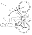
- FIG. 1 there is shown a pedal bicycle 10 being used by a rider 100.
- the bicycle 10 has a frame assembly formed by a substantially curved seat tube 12 and a down tube 14, a seat 16 secured to a substantially curved seat post 18, a handlebar 20 secured to a handlebar stem 22 which is locked in a selected height within a head tube 24 of the frame assembly and a pair of pedals 26 joined to respective crank arms 28.
- Seat stays 40 support and extend downwardly from the free end of the seat tube 12 and chain stays 42 extend rearwardly from the pedals 26 to join the seat stays 40 at or adjacent the rotation axis of the rear wheel of the bicycle 10.
- the rider 100 is seated well behind the pedals 26. Using the handlebar 20 with raised handgrips the rider 100 can pedal with a substantially straight back and has a correct anatomical support. In this position the rider 100 can pedal with optimum efficiency and power.
- the seat 16 for this embodiment does not have the usual pommel as the rider 100 is supported by the ischial tuberosities.
- This seat 16 is based on the seat disclosed in the applicant's abovementioned United States patent.
- the seat 16 is supported on an upstanding stud 30 by a clamping arrangement 32.
- the stud 30 and the clamping arrangement 32 are configured to allow a certain range of tilt adjustment of the seat 16.
- a clamping device 39 is used to clamp the post 18 to the tube 12 in a position selected by the rider.
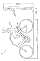
- the curved tube 12 and the post 18 determine a curved trajectory as shown by the dotted line in Figure 1 and Figure 2 which is convex relative to the seat 16. The trajectory is determined to allow the bicycle 10 to be used in comfort by a large range of body physiques.
- the curved trajectory is of a radius R substantially centred on the axis of rotation of the rear wheel of the bicycle (see Figure 1 ) such that the curved tube 12 or at least the end part thereof is substantially concentric with the rear wheel.
- R substantially centred on the axis of rotation of the rear wheel of the bicycle (see Figure 1 ) such that the curved tube 12 or at least the end part thereof is substantially concentric with the rear wheel.
- the handlebar 20 for this embodiment has a substantially U-shaped midsection 34 and handgrips 36 extending outwardly from free ends of the mid section 34.
- a brace member 38 is joined to the two arms of the mid section 34.
- the handlebar 20 is fixed in position by the handlebar stem 22, the height of which can be adjusted by positioning into the head tube 24 to a desired height and fixing it in that position by means well known in the art.
- the angular position of the handlebar 20 can also be adjusted by rotating the handlebar 20 and then fixing it in the desired angular position.
- Figure 6 shows the bicycle 10 being used by a rider 100 who is 1.5 metres tall.
- the post 1 8 is positioned substantially fully into the tube 12.
- the post 18 is in an extended position as shown in Figure 7 . In both positions the respective riders are correctly supported and can pedal with optimum efficiently.
- the inventor has used a computerised design process involving the use of anthropological data and biomechanical analysis on "Human Scale" modelling software to determine the geometry and the dimensions for (a) the bicycle frame, (b) the seat tube and seat post, (c) the pedals and cranks, and (d) the handle bar stems and the handle bars, to enable riders of all physiques to be seated in individual optimum riding positions, and to make fine adjustment to the seat position along said curve trajectory path suit differences in each rider's torso length, leg length and arm length.
- Factors for the individual optimum riding position include the combination of: (a) having the rider's body receiving skeletal support from directly beneath the ischial tuberosities (sit bones); (b) being positioned sufficiently rearward relative to the pedals for removing or at least minimising cramping of the rider's legs and to provide maximum leverage from the legs for optimising pedalling efficiency: (c) eliminating any interference with the legs during pedalling ; (d) removing pressure from the hands, arms and shoulders ; and (e) eliminating cramping of the diaphragm and restriction of lung function (breathing).
Landscapes
- Engineering & Computer Science (AREA)
- Mechanical Engineering (AREA)
- Steering Devices For Bicycles And Motorcycles (AREA)
- Braking Elements And Transmission Devices (AREA)
- Arrangement And Mounting Of Devices That Control Transmission Of Motive Force (AREA)
- Mechanical Control Devices (AREA)
- Auxiliary Drives, Propulsion Controls, And Safety Devices (AREA)
- Control Of Throttle Valves Provided In The Intake System Or In The Exhaust System (AREA)
Claims (11)
- Appareil (10) adapté pour être actionné par pédalage, comprenant un ensemble cadre (11) ayant une section avant et une section arrière avec un tube de selle creux (12), un ensemble pédalier (26, 28) comprenant des pédales (26), et une tige de selle (18) supportée par ledit tube de selle (12) et ayant des moyens de fixation (30, 32) fixant une selle (16) sur laquelle un utilisateur peut s'asseoir pendant qu'il pédale, la tige de selle (18) et le tube de selle (12) étant agencés pour soutenir la selle (16), lorsqu'elle est fixée, à une position réglable par rapport à la section arrière, ledit tube de selle (12) ayant une partie courbe agencée pour recevoir une partie courbe compatible et complémentaire de la tige de selle (18), et dans lequel les parties courbes du tube de selle (12) et de la tige de selle (18) sont configurées pour permettre le réglage télescopique de la position de la selle fixée (16) le long d'une trajectoire courbe se prolongeant vers le haut et l'arrière par rapport à ladite section arrière et de manière convexe par rapport à ladite selle (16), la position de ladite selle (16) étant réglable de manière sélective pour s'adapter à une gamme d'utilisateurs de tailles et de physiques différents, caractérisé en ce que ladite selle dans toutes les positions de ladite tige de selle (18) le long de ladite trajectoire courbe est positionnée en arrière de toute partie dudit ensemble pédalier (26, 28) et ne dépasse en avant d'aucune desdites parties, de telle sorte qu'une personne (100) assise sur ladite selle fixée (16) à la position de selle sélectionnée est derrière l'ensemble pédalier (26, 28), ce qui permet ainsi une libre action des jambes pendant le pédalage et dans lequel ladite poignée est positionnable par rapport à ladite selle de sorte qu'un utilisateur tenant ladite poignée et assis sur ladite selle a le dos dans une position essentiellement verticale dans toutes les positions de ladite selle.
- Appareil (10) selon la revendication 1, et caractérisé par une roue motrice arrière et dans lequel ladite trajectoire courbe s'étend vers le haut et l'arrière au-dessus de ladite roue arrière, ladite tige de selle (18) étant réglable par rapport audit tube de selle (12) et en arrière à partir d'une position avant dans laquelle ladite selle ne dépasse en avant d'aucune partie de ladite roue motrice arrière.
- Appareil (10) selon la revendication 2, caractérisé en ce que ladite selle (16) est réglable entre ladite position avant et une position arrière dans laquelle ladite selle (16) est située sensiblement au-dessus de l'axe de rotation de ladite roue motrice arrière.
- Appareil (10) selon la revendication 2 ou la revendication 3, caractérisé en ce que la trajectoire courbe est sensiblement concentrique avec ladite roue motrice arrière.
- Appareil (10) selon l'une quelconque des revendications 1 à 4, caractérisé en ce que ladite poignée comprend un guidon (20) et dans lequel la section avant a un tube oblique (14), un tube de direction (24) fixé au tube oblique (14), et une potence de guidon (22) ayant une extrémité agencée pour fixer le guidon (20) et une extrémité opposée agencée pour se fixer dans le tube de direction (24) d'une manière réglable en position par rapport au tube de direction (24), ledit guidon (20) ayant une section centrale essentiellement en forme de U (34), avec une poignée de guidon (36) à chacune de ses extrémités libres, ladite extrémité de la potence de guidon (22) étant agencée de telle sorte que la section centrale (34) du guidon (20) soit réglable en rotation pour être fixée à une orientation sélectionnée et offrir ainsi un réglage en avant et en arrière des poignées de guidon (36).
- Appareil (10) selon l'une quelconque des revendications précédentes, caractérisé en ce que la selle (16) est agencée pour pouvoir être réglée en inclinaison par rapport à la tige de selle (18) pour être fixée à une orientation d'inclinaison sélectionnée.
- Appareil (10) selon l'une quelconque des revendications précédentes, caractérisé par un moyen de serrage (39) pour serrer la tige de selle (18) dans ledit tube de selle (12) afin de positionner ladite selle (16) dans une position sélectionnée.
- Appareil (10) selon l'une quelconque des revendications 2 à 4 sous la forme d'une bicyclette et dans lequel ladite section avant du cadre supporte une roue avant orientable et ladite section arrière supporte une roue arrière motrice, ledit ensemble pédalier (26, 28) étant agencé entre lesdites sections avant et arrière et ledit tube de selle (12) étant disposé vers le haut et l'arrière par rapport audit ensemble pédalier (26, 28), et dans lequel ladite partie courbe dudit tube de selle (12) comprenant une partie d'extrémité courbe et dans lequel ladite partie courbe de ladite tige de selle (18) est complémentaire de ladite partie d'extrémité courbe dudit tube de selle (12) et y est reçue de manière télescopique.
- Appareil (10) selon la revendication 8 ou la revendication 9, caractérisé en ce que ladite section de cadre arrière comprend des haubans (40) soutenant l'extrémité libre dudit tube de selle (12) et disposés vers le bas par rapport à elle, et des petits tubes (42) disposés en arrière dudit ensemble pédalier (26, 28) et rejoignant lesdits haubans (40) au niveau ou à proximité de l'axe de rotation de ladite roue arrière.
- Appareil (10) selon l'une quelconque des revendications précédentes, caractérisé en ce que ladite selle (16) est configurée de telle sorte qu'une personne (100) assise dessus est supportée par les tubérosités ischiatiques.
- Appareil (10) selon l'une quelconque des revendications précédentes, caractérisé en ce que ladite selle (16) est d'un type ne comportant pas de pommeau ou de bec.
Applications Claiming Priority (3)
| Application Number | Priority Date | Filing Date | Title |
|---|---|---|---|
| AUPR773201 | 2001-09-17 | ||
| AUPR7732A AUPR773201A0 (en) | 2001-09-17 | 2001-09-17 | Pedalling apparatus |
| PCT/AU2002/001200 WO2003024771A1 (fr) | 2001-09-17 | 2002-08-30 | Velo d'interieur |
Publications (3)
| Publication Number | Publication Date |
|---|---|
| EP1444128A1 EP1444128A1 (fr) | 2004-08-11 |
| EP1444128A4 EP1444128A4 (fr) | 2007-02-28 |
| EP1444128B1 true EP1444128B1 (fr) | 2009-10-28 |
Family
ID=3831572
Family Applications (1)
| Application Number | Title | Priority Date | Filing Date |
|---|---|---|---|
| EP02759915A Expired - Lifetime EP1444128B1 (fr) | 2001-09-17 | 2002-08-30 | Velo d'interieur |
Country Status (8)
| Country | Link |
|---|---|
| US (1) | US6997470B2 (fr) |
| EP (1) | EP1444128B1 (fr) |
| JP (1) | JP2005501780A (fr) |
| CN (1) | CN1555324B (fr) |
| AT (1) | ATE446893T1 (fr) |
| AU (2) | AUPR773201A0 (fr) |
| DE (1) | DE60234203D1 (fr) |
| WO (1) | WO2003024771A1 (fr) |
Families Citing this family (10)
| Publication number | Priority date | Publication date | Assignee | Title |
|---|---|---|---|---|
| EP1689635A1 (fr) * | 2003-11-17 | 2006-08-16 | Ronny De Jong | Bicyclette comprenant un cadre fait de tubes relies entre eux de maniere qu'ils peuvent pivoter |
| FR2890038B1 (fr) | 2005-08-31 | 2008-09-05 | Marie France Molle | Cycle, notamment un tricycle. |
| FI20070192A0 (fi) * | 2007-03-06 | 2007-03-06 | Ulf Laxstroem | Pyörän runko ja pyörä |
| CN100450862C (zh) * | 2007-03-12 | 2009-01-14 | 郑达铿 | 仿生型自行车架 |
| US7571548B2 (en) * | 2007-07-26 | 2009-08-11 | Joshua David Taylor | Cycling pedal leg angle optimizer |
| NL2006053C2 (nl) | 2011-01-22 | 2012-07-24 | Andries Gaastra | Rijwiel met zadel voor de zadelpen. |
| CN102556249B (zh) * | 2012-02-21 | 2014-06-04 | 刘烈祥 | 一种自行车车架 |
| KR20130117185A (ko) * | 2012-04-18 | 2013-10-25 | 화우엔지니어링 주식회사 | 대나무를 이용하는 자전거 프레임 |
| US9669894B2 (en) * | 2013-03-15 | 2017-06-06 | Amaranti, Llc | Vehicle and vehicle components |
| US10266222B2 (en) * | 2016-09-12 | 2019-04-23 | Arkel Inc. | Bicycle rack and bag |
Family Cites Families (19)
| Publication number | Priority date | Publication date | Assignee | Title |
|---|---|---|---|---|
| US3408090A (en) * | 1966-04-04 | 1968-10-29 | Schwinn Bicycle Co | Bicycle having adjustable handlebar and seat |
| FR2037831A5 (fr) | 1969-03-10 | 1970-12-31 | Izergina Evgenia | |
| US4218090A (en) * | 1978-02-16 | 1980-08-19 | Hoffacker Bernhard J | Bicycle seat |
| US5116071A (en) * | 1989-03-09 | 1992-05-26 | Calfee Craig D | Composite bicycle frame |
| DE4325274C2 (de) * | 1993-07-28 | 1998-02-12 | Kerner Franz Dr | Fahrrad |
| DE4329795C2 (de) * | 1993-09-03 | 2001-08-16 | Franz Kerner | Fahrrad |
| FR2731671B1 (fr) * | 1995-03-13 | 1997-05-09 | Norbert Catherin | Bicyclette a grande roue motrice |
| US5823618A (en) * | 1996-02-04 | 1998-10-20 | Fox; Harry M. | Anatomically compensating size varying and adjustable shock absorbing split bicycle seat |
| AUPO028896A0 (en) * | 1996-06-07 | 1996-07-04 | Acedeal Pty Ltd | Cycle seat |
| US5779249A (en) * | 1996-09-03 | 1998-07-14 | Lin; Gin-Ding | Seat height adjusting means of a bicycle |
| US6123353A (en) * | 1997-02-19 | 2000-09-26 | Techmatics, Inc. | Method of joining and reinforcing molded plastic bicycle frames |
| IL120391A0 (en) * | 1997-03-06 | 1997-07-13 | Bonen Rami | Bicycle seat |
| DE29721591U1 (de) * | 1997-12-06 | 1998-02-19 | Porsche Ag | Fahrradrahmen |
| US6669603B1 (en) * | 1999-03-08 | 2003-12-30 | Johnny Forcillo | Stationary exercise bicycle |
| JP2000135997A (ja) * | 1998-10-30 | 2000-05-16 | Horon Create:Kk | 自転車用フレーム |
| US6193309B1 (en) * | 1999-03-12 | 2001-02-27 | Steven M. Gootter | Bicycle seat |
| US6354557B1 (en) * | 2000-03-06 | 2002-03-12 | Austin A. Walsh | Adjustable bicycles seat height assembly |
| US6499800B2 (en) * | 2001-04-17 | 2002-12-31 | Answer Products, Inc. | Seat post assembly for cycles |
| DE20113316U1 (de) * | 2001-08-18 | 2001-11-08 | Sperling Reinhard Michael | Sattelstange/Rahmenhalterung |
-
2001
- 2001-09-17 AU AUPR7732A patent/AUPR773201A0/en not_active Abandoned
-
2002
- 2002-08-30 JP JP2003528442A patent/JP2005501780A/ja active Pending
- 2002-08-30 AT AT02759915T patent/ATE446893T1/de not_active IP Right Cessation
- 2002-08-30 DE DE60234203T patent/DE60234203D1/de not_active Expired - Lifetime
- 2002-08-30 AU AU2002325662A patent/AU2002325662B2/en not_active Ceased
- 2002-08-30 CN CN028181840A patent/CN1555324B/zh not_active Expired - Fee Related
- 2002-08-30 US US10/488,934 patent/US6997470B2/en not_active Expired - Fee Related
- 2002-08-30 WO PCT/AU2002/001200 patent/WO2003024771A1/fr active Application Filing
- 2002-08-30 EP EP02759915A patent/EP1444128B1/fr not_active Expired - Lifetime
Also Published As
| Publication number | Publication date |
|---|---|
| EP1444128A4 (fr) | 2007-02-28 |
| AU2002325662B2 (en) | 2008-05-22 |
| WO2003024771A1 (fr) | 2003-03-27 |
| EP1444128A1 (fr) | 2004-08-11 |
| CN1555324B (zh) | 2010-04-28 |
| CN1555324A (zh) | 2004-12-15 |
| ATE446893T1 (de) | 2009-11-15 |
| US6997470B2 (en) | 2006-02-14 |
| AUPR773201A0 (en) | 2001-10-11 |
| DE60234203D1 (de) | 2009-12-10 |
| JP2005501780A (ja) | 2005-01-20 |
| US20040239158A1 (en) | 2004-12-02 |
Similar Documents
| Publication | Publication Date | Title |
|---|---|---|
| US4750754A (en) | Bicycle and handlebar system | |
| EP0335610B1 (fr) | Bicyclette, guidon et intermédiaire de raccord | |
| US5145210A (en) | Bicycle, handlebar and adapter system | |
| US20100186545A1 (en) | Handlebar auxiliary adjustable hand grip extension | |
| US4873886A (en) | Armrest for bicycle handlebar | |
| US5429013A (en) | Climbing handles for road bicycles | |
| US5516134A (en) | Seat for a wheeled vehicle | |
| US5201243A (en) | Handlebar assembly | |
| US5024119A (en) | Bicycle handlebars | |
| US8876136B2 (en) | Easy riding bicycle | |
| EP1444128B1 (fr) | Velo d'interieur | |
| US6120050A (en) | Training device for use with a bicycle | |
| US5201538A (en) | Ergonomic cycles | |
| US8011725B2 (en) | Bicycle rider seat brace | |
| AU2002325662A1 (en) | Pedalling apparatus | |
| US6811174B2 (en) | Sports bicycle with changeable handlebars | |
| EP1057721B1 (fr) | Selle de bicyclette | |
| US11547899B2 (en) | Procumbent exercise apparatus | |
| US20210269113A1 (en) | Adjustable Cyclist Support System | |
| WO1992021552A1 (fr) | Ensemble guidon avec colonne de direction et frein | |
| US20180065697A1 (en) | Pedal driven standing stype bicycle |
Legal Events
| Date | Code | Title | Description |
|---|---|---|---|
| PUAI | Public reference made under article 153(3) epc to a published international application that has entered the european phase |
Free format text: ORIGINAL CODE: 0009012 |
|
| 17P | Request for examination filed |
Effective date: 20040414 |
|
| AK | Designated contracting states |
Kind code of ref document: A1 Designated state(s): AT BE BG CH CY CZ DE DK EE ES FI FR GB GR IE IT LI LU MC NL PT SE SK TR |
|
| AX | Request for extension of the european patent |
Extension state: AL LT LV MK RO SI |
|
| A4 | Supplementary search report drawn up and despatched |
Effective date: 20070130 |
|
| RIC1 | Information provided on ipc code assigned before grant |
Ipc: B62K 19/36 20060101ALI20030329BHEP Ipc: B62J 1/08 20060101AFI20070124BHEP |
|
| 17Q | First examination report despatched |
Effective date: 20071127 |
|
| GRAP | Despatch of communication of intention to grant a patent |
Free format text: ORIGINAL CODE: EPIDOSNIGR1 |
|
| GRAS | Grant fee paid |
Free format text: ORIGINAL CODE: EPIDOSNIGR3 |
|
| GRAA | (expected) grant |
Free format text: ORIGINAL CODE: 0009210 |
|
| AK | Designated contracting states |
Kind code of ref document: B1 Designated state(s): AT BE BG CH CY CZ DE DK EE ES FI FR GB GR IE IT LI LU MC NL PT SE SK TR |
|
| REG | Reference to a national code |
Ref country code: GB Ref legal event code: FG4D |
|
| REG | Reference to a national code |
Ref country code: CH Ref legal event code: EP |
|
| REG | Reference to a national code |
Ref country code: IE Ref legal event code: FG4D |
|
| REF | Corresponds to: |
Ref document number: 60234203 Country of ref document: DE Date of ref document: 20091210 Kind code of ref document: P |
|
| NLV1 | Nl: lapsed or annulled due to failure to fulfill the requirements of art. 29p and 29m of the patents act | ||
| PG25 | Lapsed in a contracting state [announced via postgrant information from national office to epo] |
Ref country code: SE Free format text: LAPSE BECAUSE OF FAILURE TO SUBMIT A TRANSLATION OF THE DESCRIPTION OR TO PAY THE FEE WITHIN THE PRESCRIBED TIME-LIMIT Effective date: 20091028 Ref country code: PT Free format text: LAPSE BECAUSE OF FAILURE TO SUBMIT A TRANSLATION OF THE DESCRIPTION OR TO PAY THE FEE WITHIN THE PRESCRIBED TIME-LIMIT Effective date: 20100301 Ref country code: ES Free format text: LAPSE BECAUSE OF FAILURE TO SUBMIT A TRANSLATION OF THE DESCRIPTION OR TO PAY THE FEE WITHIN THE PRESCRIBED TIME-LIMIT Effective date: 20100208 Ref country code: FI Free format text: LAPSE BECAUSE OF FAILURE TO SUBMIT A TRANSLATION OF THE DESCRIPTION OR TO PAY THE FEE WITHIN THE PRESCRIBED TIME-LIMIT Effective date: 20091028 |
|
| PG25 | Lapsed in a contracting state [announced via postgrant information from national office to epo] |
Ref country code: CY Free format text: LAPSE BECAUSE OF FAILURE TO SUBMIT A TRANSLATION OF THE DESCRIPTION OR TO PAY THE FEE WITHIN THE PRESCRIBED TIME-LIMIT Effective date: 20091028 |
|
| PG25 | Lapsed in a contracting state [announced via postgrant information from national office to epo] |
Ref country code: BE Free format text: LAPSE BECAUSE OF FAILURE TO SUBMIT A TRANSLATION OF THE DESCRIPTION OR TO PAY THE FEE WITHIN THE PRESCRIBED TIME-LIMIT Effective date: 20091028 Ref country code: AT Free format text: LAPSE BECAUSE OF FAILURE TO SUBMIT A TRANSLATION OF THE DESCRIPTION OR TO PAY THE FEE WITHIN THE PRESCRIBED TIME-LIMIT Effective date: 20091028 |
|
| PG25 | Lapsed in a contracting state [announced via postgrant information from national office to epo] |
Ref country code: EE Free format text: LAPSE BECAUSE OF FAILURE TO SUBMIT A TRANSLATION OF THE DESCRIPTION OR TO PAY THE FEE WITHIN THE PRESCRIBED TIME-LIMIT Effective date: 20091028 Ref country code: BG Free format text: LAPSE BECAUSE OF FAILURE TO SUBMIT A TRANSLATION OF THE DESCRIPTION OR TO PAY THE FEE WITHIN THE PRESCRIBED TIME-LIMIT Effective date: 20100128 Ref country code: DK Free format text: LAPSE BECAUSE OF FAILURE TO SUBMIT A TRANSLATION OF THE DESCRIPTION OR TO PAY THE FEE WITHIN THE PRESCRIBED TIME-LIMIT Effective date: 20091028 |
|
| PG25 | Lapsed in a contracting state [announced via postgrant information from national office to epo] |
Ref country code: CZ Free format text: LAPSE BECAUSE OF FAILURE TO SUBMIT A TRANSLATION OF THE DESCRIPTION OR TO PAY THE FEE WITHIN THE PRESCRIBED TIME-LIMIT Effective date: 20091028 Ref country code: SK Free format text: LAPSE BECAUSE OF FAILURE TO SUBMIT A TRANSLATION OF THE DESCRIPTION OR TO PAY THE FEE WITHIN THE PRESCRIBED TIME-LIMIT Effective date: 20091028 |
|
| PLBE | No opposition filed within time limit |
Free format text: ORIGINAL CODE: 0009261 |
|
| STAA | Information on the status of an ep patent application or granted ep patent |
Free format text: STATUS: NO OPPOSITION FILED WITHIN TIME LIMIT |
|
| 26N | No opposition filed |
Effective date: 20100729 |
|
| PG25 | Lapsed in a contracting state [announced via postgrant information from national office to epo] |
Ref country code: GR Free format text: LAPSE BECAUSE OF FAILURE TO SUBMIT A TRANSLATION OF THE DESCRIPTION OR TO PAY THE FEE WITHIN THE PRESCRIBED TIME-LIMIT Effective date: 20100129 |
|
| PG25 | Lapsed in a contracting state [announced via postgrant information from national office to epo] |
Ref country code: IT Free format text: LAPSE BECAUSE OF FAILURE TO SUBMIT A TRANSLATION OF THE DESCRIPTION OR TO PAY THE FEE WITHIN THE PRESCRIBED TIME-LIMIT Effective date: 20091028 Ref country code: MC Free format text: LAPSE BECAUSE OF NON-PAYMENT OF DUE FEES Effective date: 20100831 |
|
| REG | Reference to a national code |
Ref country code: CH Ref legal event code: PL |
|
| PG25 | Lapsed in a contracting state [announced via postgrant information from national office to epo] |
Ref country code: LI Free format text: LAPSE BECAUSE OF NON-PAYMENT OF DUE FEES Effective date: 20100831 Ref country code: CH Free format text: LAPSE BECAUSE OF NON-PAYMENT OF DUE FEES Effective date: 20100831 |
|
| PG25 | Lapsed in a contracting state [announced via postgrant information from national office to epo] |
Ref country code: IE Free format text: LAPSE BECAUSE OF NON-PAYMENT OF DUE FEES Effective date: 20100830 |
|
| PG25 | Lapsed in a contracting state [announced via postgrant information from national office to epo] |
Ref country code: LU Free format text: LAPSE BECAUSE OF NON-PAYMENT OF DUE FEES Effective date: 20100830 Ref country code: NL Free format text: LAPSE BECAUSE OF FAILURE TO SUBMIT A TRANSLATION OF THE DESCRIPTION OR TO PAY THE FEE WITHIN THE PRESCRIBED TIME-LIMIT Effective date: 20091028 |
|
| PG25 | Lapsed in a contracting state [announced via postgrant information from national office to epo] |
Ref country code: TR Free format text: LAPSE BECAUSE OF FAILURE TO SUBMIT A TRANSLATION OF THE DESCRIPTION OR TO PAY THE FEE WITHIN THE PRESCRIBED TIME-LIMIT Effective date: 20091028 |
|
| PGFP | Annual fee paid to national office [announced via postgrant information from national office to epo] |
Ref country code: GB Payment date: 20120828 Year of fee payment: 11 |
|
| PGFP | Annual fee paid to national office [announced via postgrant information from national office to epo] |
Ref country code: FR Payment date: 20120914 Year of fee payment: 11 Ref country code: DE Payment date: 20120831 Year of fee payment: 11 |
|
| GBPC | Gb: european patent ceased through non-payment of renewal fee |
Effective date: 20130830 |
|
| PG25 | Lapsed in a contracting state [announced via postgrant information from national office to epo] |
Ref country code: DE Free format text: LAPSE BECAUSE OF NON-PAYMENT OF DUE FEES Effective date: 20140301 |
|
| REG | Reference to a national code |
Ref country code: FR Ref legal event code: ST Effective date: 20140430 |
|
| REG | Reference to a national code |
Ref country code: DE Ref legal event code: R119 Ref document number: 60234203 Country of ref document: DE Effective date: 20140301 |
|
| PG25 | Lapsed in a contracting state [announced via postgrant information from national office to epo] |
Ref country code: GB Free format text: LAPSE BECAUSE OF NON-PAYMENT OF DUE FEES Effective date: 20130830 |
|
| PG25 | Lapsed in a contracting state [announced via postgrant information from national office to epo] |
Ref country code: FR Free format text: LAPSE BECAUSE OF NON-PAYMENT OF DUE FEES Effective date: 20130902 |