EP1443515A2 - Aufzeichnungs- und Wiedergabegerät - Google Patents
Aufzeichnungs- und Wiedergabegerät Download PDFInfo
- Publication number
- EP1443515A2 EP1443515A2 EP04001981A EP04001981A EP1443515A2 EP 1443515 A2 EP1443515 A2 EP 1443515A2 EP 04001981 A EP04001981 A EP 04001981A EP 04001981 A EP04001981 A EP 04001981A EP 1443515 A2 EP1443515 A2 EP 1443515A2
- Authority
- EP
- European Patent Office
- Prior art keywords
- equipment
- section
- recording
- information
- portable
- Prior art date
- Legal status (The legal status is an assumption and is not a legal conclusion. Google has not performed a legal analysis and makes no representation as to the accuracy of the status listed.)
- Withdrawn
Links
Images



Classifications
-
- G—PHYSICS
- G11—INFORMATION STORAGE
- G11B—INFORMATION STORAGE BASED ON RELATIVE MOVEMENT BETWEEN RECORD CARRIER AND TRANSDUCER
- G11B27/00—Editing; Indexing; Addressing; Timing or synchronising; Monitoring; Measuring tape travel
- G11B27/02—Editing, e.g. varying the order of information signals recorded on, or reproduced from, record carriers
- G11B27/031—Electronic editing of digitised analogue information signals, e.g. audio or video signals
-
- G—PHYSICS
- G11—INFORMATION STORAGE
- G11B—INFORMATION STORAGE BASED ON RELATIVE MOVEMENT BETWEEN RECORD CARRIER AND TRANSDUCER
- G11B2220/00—Record carriers by type
- G11B2220/20—Disc-shaped record carriers
-
- G—PHYSICS
- G11—INFORMATION STORAGE
- G11B—INFORMATION STORAGE BASED ON RELATIVE MOVEMENT BETWEEN RECORD CARRIER AND TRANSDUCER
- G11B2220/00—Record carriers by type
- G11B2220/60—Solid state media
- G11B2220/61—Solid state media wherein solid state memory is used for storing A/V content
-
- G—PHYSICS
- G11—INFORMATION STORAGE
- G11B—INFORMATION STORAGE BASED ON RELATIVE MOVEMENT BETWEEN RECORD CARRIER AND TRANSDUCER
- G11B27/00—Editing; Indexing; Addressing; Timing or synchronising; Monitoring; Measuring tape travel
- G11B27/02—Editing, e.g. varying the order of information signals recorded on, or reproduced from, record carriers
- G11B27/031—Electronic editing of digitised analogue information signals, e.g. audio or video signals
- G11B27/034—Electronic editing of digitised analogue information signals, e.g. audio or video signals on discs
Definitions
- the present invention relates to a recording and reproducing apparatus, and in particular, to a recording and reproducing apparatus in which audio visual (AV) equipment having a reproducing function is connected to AV equipment having a recording function to provide multiple functions.
- AV audio visual
- a portable recording medium such as a memory card
- a reproducing function to reproduce AV information recorded on stationary AV equipment installed in a user's home or the'like and having a recording and reproducing function.
- Jpn. Pat. Appln. KOKAI Publication No. 2001-357618 discloses an arrangement in which content being reproduced by one of two apparatuses can be reproduced by the other apparatus without transferring the recording medium.
- Jpn. Pat. Appln. KOKAI Publication No. 2001-357618 requires that the content reproduced by one of the apparatuses be transferred and copied to the other apparatus beforehand. It is thus cumbersome for the user to handle these apparatuses.
- Jpn. Pat. Appln. KOKAI Publication No. 2000-105969 discloses an arrangement that operates when storing data read from a recording medium, on another recording medium, to determine whether or not this recording is possible on the basis of the time required to reproduce the data and the remaining time available for storing the data in the destination storage medium.
- Jpn. Pat. Appln. KOKAI Publication No. 2000-105969 does not contain any descriptions of the reproduction of information recorded in one of the apparatuses, by the other apparatus.
- the present invention is provided in view of these circumstances. It is an object of the present invention to provide a recording and reproducing apparatus in which AV equipment having a reproducing function is connected to AV equipment having a recording function to provide various functions that cannot be implemented by the single piece of equipment.
- a recording and reproducing apparatus comprising: a connecting section configured to allow external AV equipment to be controllably connected to the recording and reproducing apparatus; a selecting section configured to select one of recording media possessed by the external AV equipment, via the connecting section; and a control section configured to record or reproduce AV information, via the connecting section, on or from the recording medium selected by the selecting section.
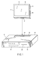
- FIG. 1 shows the appearance of an AV system described in this embodiment.
- This AV system is composed of portable AV equipment 11 and stationary AV equipment 12.
- the portable AV equipment 11 has a housing 13 formed like a thin box.
- a display section 14 is installed on one plane of the housing 13.
- An operation section 15 and an installation section 16 in which a removable medium is installed are installed on one side of the housing 13.
- a connector 17 is installed on a bottom surface of the housing 13.
- the stationary AV equipment 12 has a box-shaped housing 18.
- the housing 18 has a front pane 19.
- the operation section 20 includes a power switch and the like.
- the installation section 22 holds a removable medium.
- a mounting section 23 is formed in a top plate of the housing 18 so that a bottom surface portion of the housing 13 of the portable AV equipment 11 can be mounted in and removed from the mounting section 23.
- a connector 24 is installed in the middle of a bottom surface of the mounting section 23 and can be connected to the connector 17 of the portable AV equipment 11.
- the bottom surface portion of the housing 13 of the portable equipment 11 is fitted into the mounting section 23 of the housing 18 of the stationary AV equipment 12 to mechanically couple the AV equipment 11 to the AV equipment 12.
- the connectors 17 and 24 are also connected together to electrically connect the AV equipment 11 and the AV equipment 12 together.
- FIG. 2 shows is a block diagram illustrating the details of signal processing systems in the portable AV equipment 11 and stationary AV system 12.
- the portable AV equipment 11 comprises a tuner section 25, a built-in memory 26, a recording and reproducing section 28, an input and output section 29, and a central processing unit (CPU) 30, in addition to the display section 14, operation section 15, and installation section 16, described previously.
- CPU central processing unit
- the tuner section 25 has a function of selecting a signal of a desired channel from satellite television broadcasting and terrestrial television broadcasting, demodulating the signal, and displaying the corresponding video on the display section 14.
- the built-in memory 26 is formed of, for example, a semiconductor memory.
- the recording and reproducing section 28 has a function of recording and reproducing AV information in and from the removable medium 27 and built-in memory 26 installed in the installation section 16.
- the input and output section 29 has a function of receiving and outputting AV information, control information, or the like from and to external equipment via the connector 17.
- the CPU 30 integrally controls each section so as to reflect operation information obtained from the operation section 15.
- the stationary AV equipment 12 comprises a tuner section 31, a built-in memory 32, a recording and reproducing section 33, a timer 34, an input and output section 35, and a CPU 36, in addition to the operation section 20, display section 21, and installation section 22, described previously.
- the tuner section 31 has a function of selecting a signal of a desired channel from satellite television broadcasting and terrestrial television broadcasting and demodulating and outputting the signal to external equipment.
- the built-in memory 26 is formed of, for example, a hard disk drive (HDD).
- the timer 34 is utilized to reserve viewing or recording of television broadcasting.
- the recording and reproducing section 33 has a function of recording and reproducing AV information on and from the removable medium 37 and built-in memory 32 installed in the installation section 32.
- the input and output section 35 has a function of receiving and outputting AV information, control information, or the like from and to external equipment via the connector 24.
- the CPU 36 integrally controls each section so as to reflect operation information obtained from the operation section 20.
- the input and output sections 29 and 35 conform to the specifications of the universal serial bus (USB) MassStorage class connections. Specifically, the connection form of the portable AV equipment 11 and stationary AV equipment 12 has only to be such that their CPUs 30 and 36 can share their removable media 37 and 27 and the built-in memories 32 and 26.
- USB universal serial bus
- FIG. 3 is a flowchart schematically illustrating an example of an operation of the above AV system.
- the process is started (step S11). Then, if at step S12, a media selection menu is requested to be displayed for reproduction, then at step S13, the CPU 30 of the portable AV equipment 11 determines whether or not the stationary AV equipment 12 is connected to the portable AV equipment 11.
- the CPU 30 of the portable AV equipment determines that the stationary AV equipment 12 is not connected to the portable AV equipment 11 (NO), then at step S16, it causes the display section 14 to display the media selection menu.
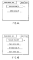
- the media selection menu displays a list of recording media possessed by the portable AV equipment 11, i.e., the removable medium 27 and the built-in memory 26 so that a user can select either of them.
- either the displayed "removable medium” 27 or “built-in memory” 26 can be selected using a frame-shaped cursor K.
- the user can operate the operating section 15 to move the cursor K to select and determine either the "removable medium” 27 or "built-in memory” 26.
- step S17 the CPU 30 of the portable AV equipment 11 reads AV information from the selected medium. Then at step S18, the CPU 30 causes the display section 14 to display a video to finish the process (step S19).
- the CPU 30 of the portable AV equipment 11 determines that the stationary AV equipment 12 is connected to the portable AV equipment 11 (YES), then at step S14, it acquires media information possessed by the stationary AV equipment 12, i.e., information as to what recording medium is provided in the stationary AV equipment 12 (in this case, the removable medium 37 and the built-in memory 32).
- the CPU 30 of the portable AV equipment 11 adds the acquired media information (the removable medium 37 and built-in memory 32) possessed by the stationary AV equipment 12 to its own media information (removable medium 27 and built-in memory 26).
- the CPU 30 causes the display section 14 to display the media selection menu.
- the media selection menu displays a list of all of the removable media 27 and 37 and built-in memories 26 and 32 possessed by the portable AV equipment 11 and stationary AV equipment 12. Any of the media can be selected and determined from this list using the cursor K.
- step S17 the CPU 30 of the portable AV equipment 11 reads AV information from the selected medium. Then at step S18, the CPU 30 causes the display section 14 to display a video to finish the process (step S19).
- the portable AV equipment 11 is operated to select either the removable medium 37 or built-in memory 32 of the stationary AV equipment 12 to read AV information recorded on the selected medium.
- the portable AV equipment 11 then causes the display section 14 to directly display the information.
- the above arrangement eliminates the need to move AV information from the stationary AV equipment 12 to the portable AV equipment 11 via the removable medium as in the case with the prior art. The user can thus handle these pieces of equipment conveniently.
- AV information acquired from the stationary AV equipment 12 is not recorded on the removable medium 27 or built-in memory 26 of the portable AV equipment 11. Accordingly, AV information can be acquired from the stationary AV equipment 12 regardless of the storage capacity of the removable medium 27 or built-in memory 26.
- the portable AV equipment 11 can select either the removable medium 37 or built-in memory 32 of the stationary AV equipment 12, in which AV information acquired from any of the tuner section 25, removable medium 27, and built-in memory 26 is subsequently recorded on its own selected medium.
- the stationary AV equipment 12 may select the tuner section 25, removable medium 27 or built-in memory 26 of the portable AV equipment 11.
- the AV information acquired from the tuner section 25, removable medium 27 or built-in memory 26 is recorded in the removable medium 37 or built-in memory of the AV equipment 12.
- the stationary AV equipment 12 can also directly supply a monitor or the like externally connected to it with AV information acquired from the portable AV equipment 11 and cause the monitor to display the AV information, without recording the information on its removable medium 37 or built-in memory 32.
- the stationary AV equipment 12 can cause the display section 14 of the portable AV equipment 11 to display AV information acquired from either its removable medium 37 or built-in memory 32 or can select the removable medium 27 or built-in memory 26 of the portable AV equipment 11, in which the AV information is subsequently recorded.
- the portable AV equipment 11 can select the built-in memory 32 of the stationary AV equipment 12 to cause the stationary AV equipment 12 to read other AV information recorded in the built-in memory 32.
- the portable AV equipment 11 can then cause the display section 14 to display the read AV information.
- the AV information recorded in the built-in memory 32 can also be read and reproduced.
- the stationary AV equipment 12 can edit other AV information recorded in the built-in memory 32.
- the stationary AV equipment 12 can read other AV information recorded in the built-in memory 32 and supply the AV information to a monitor or the like externally connected to it, which monitor then displays the information.
- the portable AV equipment 11 is coupled directly to the stationary AV equipment 12.
- the connection can be established via a cable 38 so as to form a network.
- the connection can be established by radio.
- the present invention is not limited to the above embodiment. Variations may be made to the components of the embodiment for implementation without departing from the spirit of the invention. Furthermore, various inventions can be formed by properly combining a plurality of the components disclosed in the above embodiment. For example, some of the components shown in the embodiment may be omitted.
Landscapes
- Engineering & Computer Science (AREA)
- Multimedia (AREA)
- Signal Processing For Digital Recording And Reproducing (AREA)
- Television Signal Processing For Recording (AREA)
- Signal Processing Not Specific To The Method Of Recording And Reproducing (AREA)
Applications Claiming Priority (2)
| Application Number | Priority Date | Filing Date | Title |
|---|---|---|---|
| JP2003024859 | 2003-01-31 | ||
| JP2003024859A JP2004234794A (ja) | 2003-01-31 | 2003-01-31 | 再生装置及び再生方法、記録装置及び記録方法、avシステム |
Publications (2)
| Publication Number | Publication Date |
|---|---|
| EP1443515A2 true EP1443515A2 (de) | 2004-08-04 |
| EP1443515A3 EP1443515A3 (de) | 2005-03-30 |
Family
ID=32652934
Family Applications (1)
| Application Number | Title | Priority Date | Filing Date |
|---|---|---|---|
| EP04001981A Withdrawn EP1443515A3 (de) | 2003-01-31 | 2004-01-29 | Aufzeichnungs- und Wiedergabegerät |
Country Status (3)
| Country | Link |
|---|---|
| US (1) | US20040247280A1 (de) |
| EP (1) | EP1443515A3 (de) |
| JP (1) | JP2004234794A (de) |
Families Citing this family (19)
| Publication number | Priority date | Publication date | Assignee | Title |
|---|---|---|---|---|
| JP2007172792A (ja) * | 2005-12-26 | 2007-07-05 | Kenwood Corp | オーディオシステム、および、再生制御方法 |
| JP4925749B2 (ja) * | 2006-07-06 | 2012-05-09 | パイオニア株式会社 | コンテンツ再生制御装置、コンテンツ再生制御方法、コンテンツ再生制御プログラムおよび記録媒体 |
| JP2008118507A (ja) * | 2006-11-07 | 2008-05-22 | Funai Electric Co Ltd | 放送受信装置及びデジタル放送受信機 |
| JP4842785B2 (ja) * | 2006-12-04 | 2011-12-21 | 富士通テン株式会社 | 車載用電子システム及び車載電子装置 |
| US7684200B2 (en) | 2006-12-28 | 2010-03-23 | Fujitsu Ten Limited | Electronic apparatus and electronic system |
| US20080157999A1 (en) * | 2006-12-28 | 2008-07-03 | Fujitsu Ten Limited | Electronic apparatus, electronic system and method of controlling audio output |
| US20080162044A1 (en) * | 2006-12-28 | 2008-07-03 | Fujitsu Ten Limited | In-vehicle electronic apparatus and in-vehicle electronic system |
| US8706396B2 (en) * | 2006-12-28 | 2014-04-22 | Fujitsu Ten Limited | Electronic apparatus and electronic system |
| JP2008141076A (ja) * | 2006-12-04 | 2008-06-19 | Fujitsu Ten Ltd | 携帯電子機器の着脱装置 |
| US7765046B2 (en) | 2006-12-28 | 2010-07-27 | Fujitsu Ten Limited | In-vehicle electronic apparatus and in-vehicle electronic system |
| US7774104B2 (en) * | 2006-12-27 | 2010-08-10 | Fujitsu Ten Limited | Electronic apparatus and electronic system |
| US7904236B2 (en) * | 2006-12-28 | 2011-03-08 | Fujitsu Ten Limited | Electronic apparatus and electronic system |
| JP2008137559A (ja) | 2006-12-04 | 2008-06-19 | Fujitsu Ten Ltd | 車載用電子システム、車載電子装置及び携帯電子装置の電源制御方法 |
| US20080159557A1 (en) * | 2006-12-27 | 2008-07-03 | Fujitsu Ten Limited | Electronic apparatus, electronic system and method of controlling sound output |
| US7860643B2 (en) | 2006-12-28 | 2010-12-28 | Fujitsu Ten Limited | In-vehicle detachably electronic apparatus and in-vehicle electronic system |
| US20080161950A1 (en) * | 2006-12-28 | 2008-07-03 | Fujitsu Ten Limited | Electronic system, electronic apparatus and method of operating audio unit |
| US7869196B2 (en) * | 2006-12-28 | 2011-01-11 | Fujitsu Ten Limited | Electronic apparatus |
| JP4259593B2 (ja) | 2007-06-01 | 2009-04-30 | オンキヨー株式会社 | 増幅装置およびそのプログラム |
| JP2009081730A (ja) * | 2007-09-26 | 2009-04-16 | Toshiba Corp | 記憶装置および記憶方法 |
Family Cites Families (4)
| Publication number | Priority date | Publication date | Assignee | Title |
|---|---|---|---|---|
| US20030063196A1 (en) * | 2000-05-08 | 2003-04-03 | Dennis Palatov | Handheld portable interactive data storage device |
| WO2003008060A1 (en) * | 2001-07-17 | 2003-01-30 | Nohr Steven P | Network communications entertainment system and method |
| CA2464102C (en) * | 2001-10-22 | 2021-04-13 | Apple Computer, Inc. | Intelligent synchronization for a media player |
| US20030167318A1 (en) * | 2001-10-22 | 2003-09-04 | Apple Computer, Inc. | Intelligent synchronization of media player with host computer |
-
2003
- 2003-01-31 JP JP2003024859A patent/JP2004234794A/ja active Pending
-
2004
- 2004-01-29 EP EP04001981A patent/EP1443515A3/de not_active Withdrawn
- 2004-01-29 US US10/766,523 patent/US20040247280A1/en not_active Abandoned
Also Published As
| Publication number | Publication date |
|---|---|
| EP1443515A3 (de) | 2005-03-30 |
| US20040247280A1 (en) | 2004-12-09 |
| JP2004234794A (ja) | 2004-08-19 |
Similar Documents
| Publication | Publication Date | Title |
|---|---|---|
| US20040247280A1 (en) | Recording and reproducing apparatus, recording and reproducing method, and AV system | |
| US7239800B2 (en) | Portable player for personal video recorders | |
| KR100694043B1 (ko) | Av 시스템 및 그 기능 확장 모듈 | |
| US20040095339A1 (en) | High resolution digital display system with recording capability | |
| US20040252966A1 (en) | Video storage and playback system and method | |
| US8131128B2 (en) | Audiovisual system and control method thereof | |
| US20020070960A1 (en) | Multimedia appliance | |
| US20070139558A1 (en) | Multifunctional appliance for audio/video signal processing | |
| KR101079077B1 (ko) | 멀티 시스템, 데이터 저장부 액세스 장치 및 데이터저장부 액세스 방법 | |
| EP1463314A2 (de) | Anzeigevorrichtung | |
| US20060239659A1 (en) | Removable hard disk drive | |
| CN100385564C (zh) | 具有多个再现装置的组合系统及控制其操作的方法 | |
| JP4357406B2 (ja) | 通信システム | |
| JP2000163865A (ja) | 情報転送装置 | |
| JPH11110330A (ja) | Av/pcシステム | |
| JP4275052B2 (ja) | 表示装置 | |
| KR20090014858A (ko) | 디지털 셋톱박스 | |
| KR101115976B1 (ko) | 디지털방송데이터 기록재생장치 | |
| KR100479946B1 (ko) | 보안 기능을 갖는 디지털 비디오 플레이어 | |
| EP1367578B1 (de) | Management von Optioneninformation in einem VCR/DVD-Kombinationsspieler | |
| US20060210242A1 (en) | Recording/reproduction apparatus and method | |
| KR100759140B1 (ko) | 텔레비전 시스템 | |
| KR100579523B1 (ko) | 영상 기록 제어장치 및 그의 녹화 제어 방법 | |
| KR100790071B1 (ko) | 영상 디스플레이 시스템 및 그 시스템의 제어방법 | |
| KR100809771B1 (ko) | 영상 디스플레이 시스템 및 그 시스템의 제어방법 |
Legal Events
| Date | Code | Title | Description |
|---|---|---|---|
| PUAI | Public reference made under article 153(3) epc to a published international application that has entered the european phase |
Free format text: ORIGINAL CODE: 0009012 |
|
| 17P | Request for examination filed |
Effective date: 20040129 |
|
| AK | Designated contracting states |
Kind code of ref document: A2 Designated state(s): AT BE BG CH CY CZ DE DK EE ES FI FR GB GR HU IE IT LI LU MC NL PT RO SE SI SK TR |
|
| AX | Request for extension of the european patent |
Extension state: AL LT LV MK |
|
| PUAL | Search report despatched |
Free format text: ORIGINAL CODE: 0009013 |
|
| AK | Designated contracting states |
Kind code of ref document: A3 Designated state(s): AT BE BG CH CY CZ DE DK EE ES FI FR GB GR HU IE IT LI LU MC NL PT RO SE SI SK TR |
|
| AX | Request for extension of the european patent |
Extension state: AL LT LV MK |
|
| AKX | Designation fees paid |
Designated state(s): DE FR GB |
|
| STAA | Information on the status of an ep patent application or granted ep patent |
Free format text: STATUS: THE APPLICATION HAS BEEN WITHDRAWN |
|
| 18W | Application withdrawn |
Effective date: 20061113 |