EP1443278A1 - Dehumidification method of an air conditioner - Google Patents
Dehumidification method of an air conditioner Download PDFInfo
- Publication number
- EP1443278A1 EP1443278A1 EP03292761A EP03292761A EP1443278A1 EP 1443278 A1 EP1443278 A1 EP 1443278A1 EP 03292761 A EP03292761 A EP 03292761A EP 03292761 A EP03292761 A EP 03292761A EP 1443278 A1 EP1443278 A1 EP 1443278A1
- Authority
- EP
- European Patent Office
- Prior art keywords
- humidity
- indoor
- equal
- compressor
- frequency
- Prior art date
- Legal status (The legal status is an assumption and is not a legal conclusion. Google has not performed a legal analysis and makes no representation as to the accuracy of the status listed.)
- Granted
Links
Images


Classifications
-
- F—MECHANICAL ENGINEERING; LIGHTING; HEATING; WEAPONS; BLASTING
- F24—HEATING; RANGES; VENTILATING
- F24F—AIR-CONDITIONING; AIR-HUMIDIFICATION; VENTILATION; USE OF AIR CURRENTS FOR SCREENING
- F24F3/00—Air-conditioning systems in which conditioned primary air is supplied from one or more central stations to distributing units in the rooms or spaces where it may receive secondary treatment; Apparatus specially designed for such systems
- F24F3/12—Air-conditioning systems in which conditioned primary air is supplied from one or more central stations to distributing units in the rooms or spaces where it may receive secondary treatment; Apparatus specially designed for such systems characterised by the treatment of the air otherwise than by heating and cooling
- F24F3/14—Air-conditioning systems in which conditioned primary air is supplied from one or more central stations to distributing units in the rooms or spaces where it may receive secondary treatment; Apparatus specially designed for such systems characterised by the treatment of the air otherwise than by heating and cooling by humidification; by dehumidification
- F24F3/153—Air-conditioning systems in which conditioned primary air is supplied from one or more central stations to distributing units in the rooms or spaces where it may receive secondary treatment; Apparatus specially designed for such systems characterised by the treatment of the air otherwise than by heating and cooling by humidification; by dehumidification with subsequent heating, i.e. with the air, given the required humidity in the central station, passing a heating element to achieve the required temperature
-
- F—MECHANICAL ENGINEERING; LIGHTING; HEATING; WEAPONS; BLASTING
- F24—HEATING; RANGES; VENTILATING
- F24F—AIR-CONDITIONING; AIR-HUMIDIFICATION; VENTILATION; USE OF AIR CURRENTS FOR SCREENING
- F24F11/00—Control or safety arrangements
- F24F11/30—Control or safety arrangements for purposes related to the operation of the system, e.g. for safety or monitoring
- F24F11/46—Improving electric energy efficiency or saving
-
- F—MECHANICAL ENGINEERING; LIGHTING; HEATING; WEAPONS; BLASTING
- F24—HEATING; RANGES; VENTILATING
- F24F—AIR-CONDITIONING; AIR-HUMIDIFICATION; VENTILATION; USE OF AIR CURRENTS FOR SCREENING
- F24F11/00—Control or safety arrangements
- F24F11/30—Control or safety arrangements for purposes related to the operation of the system, e.g. for safety or monitoring
-
- F—MECHANICAL ENGINEERING; LIGHTING; HEATING; WEAPONS; BLASTING
- F24—HEATING; RANGES; VENTILATING
- F24F—AIR-CONDITIONING; AIR-HUMIDIFICATION; VENTILATION; USE OF AIR CURRENTS FOR SCREENING
- F24F11/00—Control or safety arrangements
- F24F11/62—Control or safety arrangements characterised by the type of control or by internal processing, e.g. using fuzzy logic, adaptive control or estimation of values
-
- F—MECHANICAL ENGINEERING; LIGHTING; HEATING; WEAPONS; BLASTING
- F24—HEATING; RANGES; VENTILATING
- F24F—AIR-CONDITIONING; AIR-HUMIDIFICATION; VENTILATION; USE OF AIR CURRENTS FOR SCREENING
- F24F11/00—Control or safety arrangements
- F24F11/70—Control systems characterised by their outputs; Constructional details thereof
- F24F11/72—Control systems characterised by their outputs; Constructional details thereof for controlling the supply of treated air, e.g. its pressure
- F24F11/74—Control systems characterised by their outputs; Constructional details thereof for controlling the supply of treated air, e.g. its pressure for controlling air flow rate or air velocity
- F24F11/77—Control systems characterised by their outputs; Constructional details thereof for controlling the supply of treated air, e.g. its pressure for controlling air flow rate or air velocity by controlling the speed of ventilators
-
- F—MECHANICAL ENGINEERING; LIGHTING; HEATING; WEAPONS; BLASTING
- F24—HEATING; RANGES; VENTILATING
- F24F—AIR-CONDITIONING; AIR-HUMIDIFICATION; VENTILATION; USE OF AIR CURRENTS FOR SCREENING
- F24F11/00—Control or safety arrangements
- F24F11/70—Control systems characterised by their outputs; Constructional details thereof
- F24F11/80—Control systems characterised by their outputs; Constructional details thereof for controlling the temperature of the supplied air
- F24F11/86—Control systems characterised by their outputs; Constructional details thereof for controlling the temperature of the supplied air by controlling compressors within refrigeration or heat pump circuits
-
- F—MECHANICAL ENGINEERING; LIGHTING; HEATING; WEAPONS; BLASTING
- F24—HEATING; RANGES; VENTILATING
- F24F—AIR-CONDITIONING; AIR-HUMIDIFICATION; VENTILATION; USE OF AIR CURRENTS FOR SCREENING
- F24F11/00—Control or safety arrangements
- F24F11/70—Control systems characterised by their outputs; Constructional details thereof
- F24F11/80—Control systems characterised by their outputs; Constructional details thereof for controlling the temperature of the supplied air
- F24F11/87—Control systems characterised by their outputs; Constructional details thereof for controlling the temperature of the supplied air by controlling absorption or discharge of heat in outdoor units
- F24F11/871—Control systems characterised by their outputs; Constructional details thereof for controlling the temperature of the supplied air by controlling absorption or discharge of heat in outdoor units by controlling outdoor fans
-
- F—MECHANICAL ENGINEERING; LIGHTING; HEATING; WEAPONS; BLASTING
- F25—REFRIGERATION OR COOLING; COMBINED HEATING AND REFRIGERATION SYSTEMS; HEAT PUMP SYSTEMS; MANUFACTURE OR STORAGE OF ICE; LIQUEFACTION SOLIDIFICATION OF GASES
- F25B—REFRIGERATION MACHINES, PLANTS OR SYSTEMS; COMBINED HEATING AND REFRIGERATION SYSTEMS; HEAT PUMP SYSTEMS
- F25B13/00—Compression machines, plants or systems, with reversible cycle
-
- F—MECHANICAL ENGINEERING; LIGHTING; HEATING; WEAPONS; BLASTING
- F24—HEATING; RANGES; VENTILATING
- F24F—AIR-CONDITIONING; AIR-HUMIDIFICATION; VENTILATION; USE OF AIR CURRENTS FOR SCREENING
- F24F11/00—Control or safety arrangements
- F24F11/50—Control or safety arrangements characterised by user interfaces or communication
- F24F11/56—Remote control
-
- F—MECHANICAL ENGINEERING; LIGHTING; HEATING; WEAPONS; BLASTING
- F24—HEATING; RANGES; VENTILATING
- F24F—AIR-CONDITIONING; AIR-HUMIDIFICATION; VENTILATION; USE OF AIR CURRENTS FOR SCREENING
- F24F11/00—Control or safety arrangements
- F24F11/70—Control systems characterised by their outputs; Constructional details thereof
- F24F11/80—Control systems characterised by their outputs; Constructional details thereof for controlling the temperature of the supplied air
- F24F11/83—Control systems characterised by their outputs; Constructional details thereof for controlling the temperature of the supplied air by controlling the supply of heat-exchange fluids to heat-exchangers
- F24F11/84—Control systems characterised by their outputs; Constructional details thereof for controlling the temperature of the supplied air by controlling the supply of heat-exchange fluids to heat-exchangers using valves
-
- F—MECHANICAL ENGINEERING; LIGHTING; HEATING; WEAPONS; BLASTING
- F24—HEATING; RANGES; VENTILATING
- F24F—AIR-CONDITIONING; AIR-HUMIDIFICATION; VENTILATION; USE OF AIR CURRENTS FOR SCREENING
- F24F2110/00—Control inputs relating to air properties
- F24F2110/10—Temperature
-
- F—MECHANICAL ENGINEERING; LIGHTING; HEATING; WEAPONS; BLASTING
- F24—HEATING; RANGES; VENTILATING
- F24F—AIR-CONDITIONING; AIR-HUMIDIFICATION; VENTILATION; USE OF AIR CURRENTS FOR SCREENING
- F24F2110/00—Control inputs relating to air properties
- F24F2110/20—Humidity
-
- F—MECHANICAL ENGINEERING; LIGHTING; HEATING; WEAPONS; BLASTING
- F25—REFRIGERATION OR COOLING; COMBINED HEATING AND REFRIGERATION SYSTEMS; HEAT PUMP SYSTEMS; MANUFACTURE OR STORAGE OF ICE; LIQUEFACTION SOLIDIFICATION OF GASES
- F25B—REFRIGERATION MACHINES, PLANTS OR SYSTEMS; COMBINED HEATING AND REFRIGERATION SYSTEMS; HEAT PUMP SYSTEMS
- F25B2313/00—Compression machines, plants or systems with reversible cycle not otherwise provided for
- F25B2313/023—Compression machines, plants or systems with reversible cycle not otherwise provided for using multiple indoor units
- F25B2313/0234—Compression machines, plants or systems with reversible cycle not otherwise provided for using multiple indoor units in series arrangements
- F25B2313/02343—Compression machines, plants or systems with reversible cycle not otherwise provided for using multiple indoor units in series arrangements during dehumidification
-
- F—MECHANICAL ENGINEERING; LIGHTING; HEATING; WEAPONS; BLASTING
- F25—REFRIGERATION OR COOLING; COMBINED HEATING AND REFRIGERATION SYSTEMS; HEAT PUMP SYSTEMS; MANUFACTURE OR STORAGE OF ICE; LIQUEFACTION SOLIDIFICATION OF GASES
- F25B—REFRIGERATION MACHINES, PLANTS OR SYSTEMS; COMBINED HEATING AND REFRIGERATION SYSTEMS; HEAT PUMP SYSTEMS
- F25B2313/00—Compression machines, plants or systems with reversible cycle not otherwise provided for
- F25B2313/029—Control issues
- F25B2313/0293—Control issues related to the indoor fan, e.g. controlling speed
-
- F—MECHANICAL ENGINEERING; LIGHTING; HEATING; WEAPONS; BLASTING
- F25—REFRIGERATION OR COOLING; COMBINED HEATING AND REFRIGERATION SYSTEMS; HEAT PUMP SYSTEMS; MANUFACTURE OR STORAGE OF ICE; LIQUEFACTION SOLIDIFICATION OF GASES
- F25B—REFRIGERATION MACHINES, PLANTS OR SYSTEMS; COMBINED HEATING AND REFRIGERATION SYSTEMS; HEAT PUMP SYSTEMS
- F25B2313/00—Compression machines, plants or systems with reversible cycle not otherwise provided for
- F25B2313/029—Control issues
- F25B2313/0294—Control issues related to the outdoor fan, e.g. controlling speed
-
- F—MECHANICAL ENGINEERING; LIGHTING; HEATING; WEAPONS; BLASTING
- F25—REFRIGERATION OR COOLING; COMBINED HEATING AND REFRIGERATION SYSTEMS; HEAT PUMP SYSTEMS; MANUFACTURE OR STORAGE OF ICE; LIQUEFACTION SOLIDIFICATION OF GASES
- F25B—REFRIGERATION MACHINES, PLANTS OR SYSTEMS; COMBINED HEATING AND REFRIGERATION SYSTEMS; HEAT PUMP SYSTEMS
- F25B2600/00—Control issues
- F25B2600/02—Compressor control
- F25B2600/025—Compressor control by controlling speed
- F25B2600/0253—Compressor control by controlling speed with variable speed
-
- F—MECHANICAL ENGINEERING; LIGHTING; HEATING; WEAPONS; BLASTING
- F25—REFRIGERATION OR COOLING; COMBINED HEATING AND REFRIGERATION SYSTEMS; HEAT PUMP SYSTEMS; MANUFACTURE OR STORAGE OF ICE; LIQUEFACTION SOLIDIFICATION OF GASES
- F25B—REFRIGERATION MACHINES, PLANTS OR SYSTEMS; COMBINED HEATING AND REFRIGERATION SYSTEMS; HEAT PUMP SYSTEMS
- F25B2700/00—Sensing or detecting of parameters; Sensors therefor
- F25B2700/02—Humidity
-
- F—MECHANICAL ENGINEERING; LIGHTING; HEATING; WEAPONS; BLASTING
- F25—REFRIGERATION OR COOLING; COMBINED HEATING AND REFRIGERATION SYSTEMS; HEAT PUMP SYSTEMS; MANUFACTURE OR STORAGE OF ICE; LIQUEFACTION SOLIDIFICATION OF GASES
- F25B—REFRIGERATION MACHINES, PLANTS OR SYSTEMS; COMBINED HEATING AND REFRIGERATION SYSTEMS; HEAT PUMP SYSTEMS
- F25B49/00—Arrangement or mounting of control or safety devices
- F25B49/02—Arrangement or mounting of control or safety devices for compression type machines, plants or systems
- F25B49/022—Compressor control arrangements
-
- Y—GENERAL TAGGING OF NEW TECHNOLOGICAL DEVELOPMENTS; GENERAL TAGGING OF CROSS-SECTIONAL TECHNOLOGIES SPANNING OVER SEVERAL SECTIONS OF THE IPC; TECHNICAL SUBJECTS COVERED BY FORMER USPC CROSS-REFERENCE ART COLLECTIONS [XRACs] AND DIGESTS
- Y02—TECHNOLOGIES OR APPLICATIONS FOR MITIGATION OR ADAPTATION AGAINST CLIMATE CHANGE
- Y02B—CLIMATE CHANGE MITIGATION TECHNOLOGIES RELATED TO BUILDINGS, e.g. HOUSING, HOUSE APPLIANCES OR RELATED END-USER APPLICATIONS
- Y02B30/00—Energy efficient heating, ventilation or air conditioning [HVAC]
- Y02B30/70—Efficient control or regulation technologies, e.g. for control of refrigerant flow, motor or heating
Definitions
- the present invention relates to a dehumidification operation method of an air condition, and more particularly to a power dehumidification operation method of an air condition, in which the compressor frequency is determined according to the humidity difference between a set humidity and the indoor humidity, and the revolution rate of an outdoor fan is adjusted according to the temperature difference between a set temperature and the indoor temperature to thereby minimize an arrival time of the set humidity.
- an air conditioner provided with a dehumidification function is aimed to remove moisture by arranging a first heat exchanger functioning as a condenser and a second heat exchanger functioning as an evaporator in an indoor heat exchanger unit which is disposed indoors.
- FIG. 1 schematically shows a conventional air conditioner 1.
- a conventional air conditioner with a dehumidification function includes a compressor unit 10 for compressing coolant, an outdoor heat exchanger unit 20, an indoor heat exchanger unit 30 and an expansion unit 40 disposed between the outdoor heat exchanger unit 20 and the indoor heat exchanger unit 30.
- the outdoor heat exchanger unit 20 has a heat exchanger 21 and a fan 22 to enable heat exchange between coolant and outdoor air.
- the indoor heat exchanger unit 30 has a first heat exchanger 31, a second heat exchanger 32 and indoor expanders 33 and 34 disposed between the first and the second heat exchangers 31 and 32.
- the compressor unit 10 has a compressor 11 for converting low temperature and pressure gas coolant dispensed from the outdoor heat exchanger unit 20 or the indoor heat exchanger unit 30 into high temperature and pressure gas coolant, and a four-way valve 12 for regulating the dispensing direction of the compressor 11.
- the four-way valve 12 switches suction and exhaust ducts of the compressor 11 so that the indoor heat exchanger unit 30 may operate as an evaporator in the event of cooling the indoor or as a condenser in the event of heating the indoor.
- the outdoor heat exchanger unit 20 naturally operates as the condenser or the evaporator correspondingly.
- the outdoor heat exchanger unit 20 serves to convert high temperature and pressure gas coolant generated in the compressor unit 10 into middle temperature and high pressure liquid coolant, and is equipped with the condenser 21 and the fan 22 to this end.
- the expansion unit 40 is means for converting middle temperature-high pressure liquid coolant dispensed from the outdoor heat exchanger unit 20 into low temperature-pressure liquid coolant.
- the expansion unit 40 includes a capillary 41 and a first valve 42 disposed parallel with the capillary 41 for regulating flow of liquid coolant through the capillary 41.
- the air conditioner operates as a dehumidifier, it is necessary to control the pass of the coolant through the capillary 41 such that the expansion cycle in the expansion unit 40 does not occur.
- the first valve 42 is opened such that the liquid coolant passes through the first valve 42, so that the expansion unit 40 will not perform an expansion cycle.
- the expansion cycle is not performed as above, middle temperature-high pressure coolant is introduced into the indoor heat exchanger unit 30. Then, since the indoor heat exchanger unit 30 includes the first heat exchanger 31, the second heat exchanger 32 and the indoor expanders 33 and 34 between the first and second heat exchangers 31 and 32, the first heat exchanger 31 performs a condensing action once more while the indoor expander 33 performs the expansion cycle.
- middle temperature-high pressure liquid coolant is converted into low temperature-pressure liquid coolant, and the converted low temperature-pressure liquid coolant in the second heat exchanger 32 absorbs surrounding heat to be evaporated into low temperature-pressure gas coolant and the evaporated low temperature-pressure gas coolant is then introduced into the compressor unit 10.
- the expansion unit 40 performs the expansion cycle and the first heat exchanger 31 operates as an evaporator like the second heat exchanger 32. At this time, of course, the second valve 34 of the indoor expander 33 is opened to disable the indoor expander 33.
- the second heat exchanger 32 As the temperature drops owing to evaporation of coolant, ambient moisture is condensed. Thus condensed moisture is discharged to the outside to carry out the dehumidification operation.
- the first heat exchanger 31 operates as a condenser to have temperature balance, thereby preventing the indoor temperature from dropping.
- the conventional air conditioner performs the dehumidification operation regardless of the humidity difference between the set humidity and the indoor humidity, and the outdoor load, so that it fails to optimize the operations of the outdoor fan of the outdoor unit and the compressor. Also, it takes a long time to arrive at the set humidity in the operation of the air conditioner.
- the present invention is directed to a power dehumidification operation method of an air conditioner that substantially obviates one or more problems due to limitations and disadvantages of the related art.
- An object of the present invention is to provide a power dehumidification operation method of an air conditioner, in which the compressor frequency is determined according to the humidity difference between a set humidity and the indoor humidity, and the revolution rate of an outdoor fan is adjusted according to the temperature difference between a set temperature and the indoor temperature to thereby optimize the operations of the outdoor fan and compressor and minimize an arrival time of the set humidity.
- a power dehumidification operation method of an air conditioner comprises the steps of: (a) detecting an indoor humidity by an indoor humidity sensor installed in the air conditioner and comparing the detected indoor humidity with a set humidity (which is set by a controller including a remote controller) to obtain a humidity difference between the detected indoor humidity and the set humidity; (b) setting the frequency of a compressor via a compressor-operating algorithm according to the humidity difference obtained in the step (a); (c) detecting an indoor temperature by an indoor temperature sensor installed in the air conditioner, and comparing the detected indoor temperature with a set temperature (which is set by the controller) to obtain a temperature difference between the detected indoor temperature and the set temperature; (d) setting the revolution rate of an outdoor fan via an outdoor fan-operating algorithm according to the temperature difference obtained in the step (c); and (e) operating the indoor and outdoor fans and the compressor according to the revolution rates and the frequency set in the steps (
- the power humidification operation method may further comprise the feedback control step of: continuously judging whether the indoor humidity exists in a comfortable range and whether the uniform indoor temperature is maintained so as to maintain the indoor dehumidification and uniform indoor temperature in the comfortable region state, and repeating the steps (a) to (e) until the indoor humidity exists in the comfortable range and the uniform indoor temperature is satisfied.
- FIG. 1 schematically shows a conventional air conditioner
- FIG. 2 is a flowchart illustrating a power dehumidification operation method of an air conditioner according to the invention
- FIG. 3 is a flowchart for setting the compressor frequency of a compressor via dehumidifying ability judgment in a power dehumidification operation method of an air conditioner according to the invention.
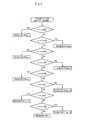
- FIG. 4 is a flowchart for setting the revolution rate of an outdoor fan via a cooling tendency in a power dehumidification operation method of an air conditioner according to the invention.
- FIG. 2 is a flowchart illustrating a power dehumidification operation method of an air conditioner according to the invention.
- a power dehumidification operation method of an air conditioner comprises the steps of: (a) detecting an indoor humidity by an indoor humidity sensor installed in the air conditioner and comparing the detected indoor humidity with a set humidity (which is set by a controller including a remote controller) to obtain a humidity difference between the detected indoor humidity and the set humidity; (b) setting the frequency of a compressor via a compressor-operating algorithm according to the humidity difference obtained in the step (a); (c) detecting an indoor temperature by an indoor temperature sensor installed in the air conditioner, and comparing the detected indoor temperature with a set temperature (which is set by the controller) to obtain a temperature difference between the detected indoor temperature and the set temperature; (d) setting the revolution rate of an outdoor fan via an outdoor fan-operating algorithm according to the temperature difference obtained in the step (c); and (e) operating the indoor and outdoor fans and the compressor according to the revolution rates and the frequency set in the steps (b) to (d), whereby an indoor dehumidification operation is continuously performed and a uniform indoor temperature is maintained in
- the power humidification operation method may further comprise the feedback control step of: continuously judging whether the indoor humidity exists in a comfortable range and whether the uniform indoor temperature is maintained so as to maintain the indoor dehumidification and uniform indoor temperature in the comfortable region state, and repeating the steps (a) to (e) until the indoor humidity exists in the comfortable range and the uniform indoor temperature is satisfied.
- the revolution rate of the indoor fan is continuously maintained at a 'special strong wind' that is the maximum revolution rate of the indoor fan while the power dehumidification operation is kept from an initial stage where the power dehumidification is selected and operated.
- the indoor humidity is detected by an indoor humidity sensor installed in the air conditioner 1.
- the detected indoor humidity is compared with a set humidity (i.e., humidity which is set by a controller such as a remote controller) to obtain the humidity difference.
- a set humidity i.e., humidity which is set by a controller such as a remote controller
- the indoor temperature is detected by an indoor temperature sensor installed in the air conditioner 1.
- the detected indoor temperature is compared with a set temperature (i.e., temperature which is set by a controller such as a remote controller) to obtain the temperature difference (S201).
- a sub-routine process for judging dehumidifying ability is carried out (S202).
- the frequency of the compressor 11 is set via a compressor-operating algorithm according to the obtained humidity difference between the indoor humidify and the set humidify.
- a revolution rate of the outdoor fan 22 is set through the outdoor fan-operating algorithm according to the temperature difference between the indoor temperature and the set temperature obtained in the step S201.
- the outdoor fan-operating algorithm judges whether or not the temperature difference is 0 (S203), if the temperature difference is 0, performs the sub-routine process for uniform temperature (determining the revolution rate of the outdoor fan) (S204), and if the temperature difference is not 0, performs a cooling tendency sub-routine process (determining the revolution rate of the outdoor fan) (S205).
- the outdoor fan-operating algorithm indicates the cooling tendency sub-routine process.
- the compressor 11 and the outdoor fan 22 are actuated to consecutively maintain a comfortable indoor dehumidification and uniform indoor temperature operation at the set frequency of the compressor 11 and the revolution rate of the outdoor fan 22 that a user can feel a comfortable indoor atmosphere (S206).
- the outdoor fan and the compressor are operated to achieve objects of the uniform indoor temperature and the indoor dehumidification, and then the uniform indoor temperature and the indoor dehumidification are confirmed via a feedback system. If both the uniform indoor temperature and the indoor dehumidification are satisfied, the health dehumidification operation method of an air conditioner according to the invention is completed.
- the revolution rate of the indoor fan 35 is regulated to maintain the "special strong wind mode" during the power dehumidification operation from an initial stage in which the health dehumidification is selected and performed.
- FIG. 3 is a flowchart of a compressor-operating algorithm for setting the frequency of the compressor as a method of judging dehumidification ability in the power dehumidification operation of an air conditioner of the invention.
- the compressor-operating algorithm includes: a first step of detecting the indoor humidity by the indoor humidity sensor (not shown) installed in the air conditioner 1 and comparing the detected indoor humidity with the set humidity (which is set by a controller such as a remote controller) to obtain the humidity difference between the detected indoor humidity and the set humidity; a second step of comparing the humidity difference obtained in the first step with a reference humidity difference set in the air conditioner 1; and a third step of setting the frequency of the compressor 11 corresponding to the humidity difference (indoor humidity - set humidity) according to comparison in the second step.
- Table 1 reports a situation in which the frequency of the compressor 11 is adjustably controlled according to the humidity difference obtained through comparison between the indoor humidity and the set humidity (i.e., humidity set by a controller such as a remote controller) using the compressor-operating algorithm, in which ⁇ H is the humidity difference between the indoor humidity and the set humidity, and F is the rotation frequency of the compressor.
- H Set humidity - indoor humidity COMP F (Dehumidification Ability) H F H ⁇ 30% F max 25% ⁇ H ⁇ 29% F max 20% ⁇ H ⁇ 24% F max 15% ⁇ H ⁇ 19% F max 10% ⁇ H ⁇ 14% F max 5% ⁇ H ⁇ 9% F max -1 0% ⁇ H ⁇ 4% F max -2 - 5% ⁇ H ⁇ -1% F max -3 H ⁇ -6% OFF
- the frequency of the compressor 11 is set to a maximum rotational frequency (F max ).
- F max the maximum rotational frequency
- the compressor-operating algorithm sets the frequency to a first compressor frequency F max-1 that is lower by one step than the maximum rotational frequency (F max ).
- the compressor-operating algorithm sets the frequency to a second compressor frequency F max-2 that is lower by one step than the first compressor frequency F max-1 .
- the compressor-operating algorithm sets the frequency to a third compressor frequency F max-3 that is lower by one step than the second compressor frequency F max-2 .
- the compressor-operating algorithm sets the frequency to 0 (OFF).
- FIG. 4 is a flowchart for setting the revolution rate of an outdoor fan via a cooling tendency when the temperature difference is not 0 in a power saving dehumidification operation method of an air conditioner according to the invention.
- the outdoor fan-operating algorithm includes: a first step of comparing the frequency of the compressor 11 adjustably controlled via the compressor-operating algorithm with the indoor humidity detected by the indoor humidity sensor installed in the air conditioner 1; and a second step of setting the revolution rate of the outdoor fan 22 in proportion with the adjustably controlled frequency of the compressor 11, whereby the indoor dehumidification operation can be performed in a pleasant condition via the adjustably controlled frequency of the compressor 11.
- Table 2 reports a situation in which the revolution rate of the outdoor fan is adjustably controlled via the outdoor fan-operating algorithm according to the frequency and the indoor humidity of the compressor 11 set in Table 1.
- the humidity difference ( ⁇ H) is a difference between indoor humidity and set humidity.
- the revolution rate of the outdoor fan 22 is set to 46.
- the revolution rate of the outdoor fan is set to 54.
- the revolution rate of the outdoor fan 22 is set to 62.
- the revolution rate of the outdoor fan 22 is set to 69.
- the revolution rate of the outdoor fan 22 is set to 77.
- the revolution rate of the outdoor fan 22 is set to 85.
- the revolution rate of the outdoor fan 22 is set to 92.
- the revolution rate of the outdoor fan 22 is set to 100.
- the revolution rate of the outdoor fan 22 is set to 0 (OFF).
- the frequency of the compressor 11 is set as follows.
- the indoor humidity is detected by the indoor humidity sensor (not shown) installed in the air conditioner.
- the detected indoor humidity is compared with a set humidity (i.e., humidity which is set by a controller such as remote controller) to obtain a difference between the detected indoor humidity and the set humidity.
- the humidity difference between the indoor humidity and the set humidity is compared with the reference humidity difference in the air conditioner 1 to set the frequency of the compressor 11 corresponding to the humidity difference (indoor humidity - set humidity).
- the revolution rate of the outdoor fan 22 is set via the outdoor fan-operating algorithm so as to maintain or keep the indoor temperature uniform so that the indoor dehumidification operation be performed in a comfortable condition.
- the indoor dehumidification operation is performed in the pleasant condition where the user can feel a pleasant indoor atmosphere. Also, the above steps are repeatedly carried out by continuously judging whether the indoor humidity exists in a comfortable range.
- the a health dehumidification operation method of an air conditioner of the present invention optimizes the operation of the compressor, the indoor fan and the outdoor fan in response to the outdoor load in the air conditioner.
- the present invention minimizes an arrival time to a set humidity.
Abstract
Description
| H: Set humidity - indoor humidity | ||
| COMP F (Dehumidification Ability) | ||
| H | F | |
| H≥ 30% | Fmax | |
| 25%≤ H≤ 29 | F | max |
| 20%≤ H≤ 24% | Fmax | |
| 15%≤ H≤ 19 | F | max |
| 10%≤ H≤ 14% | Fmax | |
| 5%≤ H≤ 9% | Fmax -1 | |
| 0%≤ H≤ 4% | Fmax -2 | |
| - 5%≤ H≤ -1% | Fmax -3 | |
| H ≤ -6% | OFF |
Here, the humidity difference (ΔH) is a difference between indoor humidity and set humidity.
| H: Set humidity - indoor humidity [Unit: Percent] | |
| Outdoor Fan (Cooling Ability) | |
| H | Outdoor fan |
| H≥ 30% | 46 |
| 25%≤ H≤ 29% | 54 |
| 20%≤ H≤ 24% | 62 |
| 15%≤ H≤ 19% | 69 |
| 10%≤ H≤ 14% | 77 |
| 5%≤ H≤ 9% | 85 |
| 0%≤ H≤ 4% | 92 |
| - 5%≤ H≤ -1% | 100 |
| H≤ -6% | OFF |
Claims (14)
- A power dehumidification operation method of an air conditioner, the method comprising the steps of:(a) detecting an indoor humidity by an indoor humidity sensor installed in the air conditioner and comparing the detected indoor humidity with a set humidity (which is set by a controller including a remote controller) to obtain a humidity difference between the detected indoor humidity and the set humidity;(b) setting the frequency of a compressor via a compressor-operating algorithm according to the humidity difference obtained in the step (a);(c) detecting an indoor temperature by an indoor temperature sensor installed in the air conditioner, and comparing the detected indoor temperature with a set temperature (which is set by the controller) to obtain a temperature difference between the detected indoor temperature and the set temperature;(d) setting the revolution rate of an outdoor fan via an outdoor fan-operating algorithm according to the temperature difference obtained in the step (c); and(e) operating the indoor and outdoor fans and the compressor according to the revolution rates and the frequency set in the steps (b) to (d), whereby an indoor dehumidification operation is continuously performed and a uniform indoor temperature is maintained in a comfortable region state so that a user can feel a comfortable indoor environment.
- The power dehumidification operation method according to claim 1, further comprising the feedback control step of:(f) continuously judging whether the indoor humidity exists in a comfortable range and whether the uniform indoor temperature is maintained so as to maintain the indoor dehumidification and uniform indoor temperature in the comfortable region state, and repeating the steps (a) to (e) until the indoor humidity exists in the comfortable range and the uniform indoor temperature is satisfied.
- The power dehumidification operation method according to claim 1, wherein the compressor-operating algorithm comprises the steps of:(i) detecting the indoor humidity by the indoor humidity sensor installed in the air conditioner and comparing the detected indoor humidity with the set humidity to obtain the humidity difference between the detected indoor humidity and the set humidity;(ii) comparing the humidity difference obtained in the step (i) with a reference humidity difference set in the air conditioner; and(iii) setting the frequency of the compressor corresponding to the humidity difference (indoor humidity - set humidity) according to comparison in the step (ii).
- The power dehumidification operation method according to claim 1, wherein the compressor-operating algorithm sets the frequency of the compressor to a maximum rotational frequency (Fmax) if the humidity difference is 30% or more, maintains the maximum rotational frequency if the humidity difference is greater than or equal to 10% and less than or equal to 29%, sets the frequency to a first compressor frequency Fmax-1 that is lower by one step than the maximum rotational frequency if the humidity difference is greater than or equal to 5% and less than or equal to 9%, to a second compressor frequency Fmax-2 that is lower by one step than the first compressor frequency Fmax-1 if the humidity difference is greater than or equal to 0% and less than or equal to 4%, to a third compressor frequency Fmax-3 that is lower by one step than the second compressor frequency Fmax-2 if the humidity difference is greater than or equal to -5% and less than or equal to -1%, and to 0 (OFF) if the humidity difference is -6% or less.
- The power dehumidification operation method according to claim 1, wherein the outdoor fan-operating algorithm comprises the steps of:(i) comparing the frequency of the compressor adjustably controlled via the compressor-operating algorithm with the indoor humidity detected by the indoor humidity sensor installed in the air conditioner; and(ii) setting the revolution rate of the outdoor fan in proportion with the adjustably controlled frequency of the compressor, whereby the indoor dehumidification operation can be performed in a pleasant condition via the adjustably controlled frequency of the compressor.
- The power dehumidification operation method according to claim 1, wherein the outdoor fan-operating algorithm sets the revolution rate of the outdoor fan to different values corresponding to the humidity difference steps, and
under a condition that a reference revolution rate of the outdoor fan is set to 46 when the humidity difference is 30% or more, the revolution rate of the outdoor fan is set to 54 when the humidity difference is greater than or equal to 25% and less than or equal to 29%, to 62 when the humidity difference is greater than or equal to 20% and less than or equal to 24%, to 69 when the humidity difference is greater than or equal to 15% and less than or equal to 19%, to 77 when the humidity difference is greater than or equal to 10% and less than or equal to 14%, to 85 when the humidity difference is greater than or equal to 5% and less than or equal to 9%, to 92 when the humidity difference is greater than or equal to 0% and less than or equal to 4%, to 100 when the humidity difference is greater than or equal to -5% and less than or equal to -1%, and to 0 (OFF) when the humidity difference is - 6% or less. - The power dehumidification operation method according to claim 1, wherein the revolution rate of the indoor fan is continuously maintained at a 'special strong wind' that is the maximum revolution rate of the indoor fan while the power dehumidification operation is kept from an initial stage where the power dehumidification is selected and operated.
- An indoor power dehumidification operation method of an air conditioner, the method comprising the steps of:(a) determining the frequency of a compressor via a compressor-operating algorithm according to a humidity difference between a set humidity and an indoor humidity; and(b) adjusting the revolution rate of an outdoor fan via an outdoor fan-operating algorithm according to a temperature difference between a reference temperature and an indoor temperature.
- The power dehumidification operation method according to claim 8, further comprising the feedback control step of:(c) continuously judging whether the indoor humidity exists in a comfortable range and whether the uniform indoor temperature is maintained so as to maintain the indoor dehumidification and uniform indoor temperature in the comfortable region state, and repeating the steps (a) and (b) until the indoor humidity exists in the comfortable range and the uniform indoor temperature is satisfied.
- The power dehumidification operation method according to claim 8, wherein the compressor-operating algorithm comprises the steps of:(i) detecting the indoor humidity by the indoor humidity sensor installed in the air conditioner and comparing the detected indoor humidity with the set humidity to obtain the humidity difference between the detected indoor humidity and the set humidity;(ii) comparing the humidity difference obtained in the step (i) with a reference humidity difference set in the air conditioner; and(iii) setting the frequency of the compressor corresponding to the humidity difference (indoor humidity - set humidity) according to comparison in the step (ii).
- The power dehumidification operation method according to claim 8, wherein the compressor-operating algorithm sets the frequency of the compressor to a maximum rotational frequency (Fmax) if the humidity difference is 30% or more, maintains the maximum rotational frequency if the humidity difference is greater than or equal to 10% and less than or equal to 29%, sets the frequency to a first compressor frequency Fmax-1 that is lower by one step than the maximum rotational frequency if the humidity difference is greater than or equal to 5% and less than or equal to 9%, to a second compressor frequency Fmax-2 that is lower by one step than the first compressor frequency Fmax-1 if the humidity difference is greater than or equal to 0 and less than or equal to 4%, to a third compressor frequency Fmax-3 that is lower by one step than the second compressor frequency Fmax-2 if the humidity difference is greater than or equal to -5% and less than or equal to -1%, and to 0 (OFF) if the humidity difference is -6% or less.
- The power dehumidification operation method according to claim 8, wherein the outdoor fan-operating algorithm includes the steps of:(i) comparing the frequency of the compressor adjustably controlled via the compressor-operating algorithm with the indoor humidity detected by the indoor humidity sensor installed in the air conditioner; and(ii) setting the revolution rate of the outdoor fan in proportion with the adjustably controlled frequency of the compressor, whereby an indoor dehumidification operation can be performed in a pleasant condition via the adjustably controlled frequency of the compressor.
- A power dehumidification operation method according to claim 8, wherein the outdoor fan-operating algorithm sets the revolution rate of the outdoor fan to different values corresponding to the humidity difference steps, and
under a condition that a reference revolution rate of the outdoor fan is set to 46 if the humidity difference is 30% or more, the revolution rate of the outdoor fan is set to 54 if the humidity difference is greater than or equal to 25% and less than or equal to 29%, to 62 if the humidity difference is greater than or equal to 20% and less than or equal to 24%, to 69 if the humidity difference is greater than or equal to 15% and less than or equal to 19%, to 77 if the humidity difference is greater than or equal to 10% and less than or equal to 14%, to 85 if the humidity difference is greater than or equal to 5% and less than or equal to 9%, to 92 if the humidity difference is greater than or equal to of 0% and less than or equal to 4%, to 100 if the humidity difference is greater than or equal to -5% and less than or equal to -1%, and to 0 (OFF) if the humidity difference is -6% or less. - The power dehumidification operation method according to claim 8, wherein the revolution rate of the indoor fan is continuously maintained at a 'special strong wind' that is the maximum revolution rate of the indoor fan while the power dehumidification operation is kept from an initial stage where the power dehumidification is selected and operated.
Applications Claiming Priority (2)
| Application Number | Priority Date | Filing Date | Title |
|---|---|---|---|
| KR10-2003-0006085A KR100512281B1 (en) | 2003-01-30 | 2003-01-30 | Method for dehumidification of air conditioner |
| KR2003006085 | 2003-01-30 |
Publications (2)
| Publication Number | Publication Date |
|---|---|
| EP1443278A1 true EP1443278A1 (en) | 2004-08-04 |
| EP1443278B1 EP1443278B1 (en) | 2007-02-14 |
Family
ID=32653317
Family Applications (1)
| Application Number | Title | Priority Date | Filing Date |
|---|---|---|---|
| EP03292761A Expired - Fee Related EP1443278B1 (en) | 2003-01-30 | 2003-11-04 | Dehumidification method of an air conditioner |
Country Status (4)
| Country | Link |
|---|---|
| EP (1) | EP1443278B1 (en) |
| JP (1) | JP2004233046A (en) |
| KR (1) | KR100512281B1 (en) |
| CN (1) | CN100436954C (en) |
Cited By (13)
| Publication number | Priority date | Publication date | Assignee | Title |
|---|---|---|---|---|
| ITPD20080247A1 (en) * | 2008-08-08 | 2010-02-09 | Carel S P A | PROCEDURE FOR CONTROL OF HUMIDITY RELATED TO ENVIRONMENTS |
| CN103375868A (en) * | 2012-04-12 | 2013-10-30 | 珠海格力电器股份有限公司 | Air-conditioner temperature control and dehumidification control method |
| CN107969142A (en) * | 2014-07-21 | 2018-04-27 | 曾国辉 | Indoor climate adjustment equipment and its control method |
| US10077912B2 (en) | 2013-11-29 | 2018-09-18 | Coway Co., Ltd. | Dehumidifier and method for controlling operation of dehumidifier |
| CN110243025A (en) * | 2019-06-25 | 2019-09-17 | 江苏友奥电器有限公司 | A kind of control method and device of frequency conversion dehumidifier |
| CN110849006A (en) * | 2019-11-12 | 2020-02-28 | 深圳孚沃德斯科技有限公司 | Variable-frequency energy-saving transformation system and method suitable for precision air conditioner of fixed-frequency compressor |
| EP3677851A4 (en) * | 2017-09-04 | 2020-11-04 | Haier Group Corporation | Self-cleaning control method and apparatus for air conditioner |
| CN113531760A (en) * | 2021-06-03 | 2021-10-22 | 珠海格力电器股份有限公司 | Humidity control method and device, storage medium and processor |
| CN113932410A (en) * | 2021-09-26 | 2022-01-14 | 青岛海尔空调器有限总公司 | Air conditioner control method and device and air conditioner |
| CN114135974A (en) * | 2021-11-26 | 2022-03-04 | 宁波奥克斯电气股份有限公司 | Air conditioner control method and device and air conditioner |
| CN114234505A (en) * | 2021-12-20 | 2022-03-25 | 珠海格力电器股份有限公司 | Control method and device of refrigerating unit, refrigerating unit and storage medium |
| CN114543282A (en) * | 2022-02-21 | 2022-05-27 | 青岛海信日立空调系统有限公司 | Air conditioner dehumidification control method and system |
| CN115307262A (en) * | 2022-07-04 | 2022-11-08 | 珠海格力电器股份有限公司 | Constant-temperature dehumidification method and device for air conditioner and air conditioning system |
Families Citing this family (31)
| Publication number | Priority date | Publication date | Assignee | Title |
|---|---|---|---|---|
| CN101718459B (en) * | 2009-11-10 | 2012-05-23 | 广东美的电器股份有限公司 | Method for controlling inverter air conditioner |
| CN102519125B (en) * | 2011-12-30 | 2014-09-17 | 宁波奥克斯空调有限公司 | Movable dehumidifier and control method thereof |
| CN103375876B (en) * | 2012-04-25 | 2015-09-16 | 珠海格力电器股份有限公司 | The dehumidification control method of air-conditioner and control method, device and air-conditioner |
| CN102865648A (en) * | 2012-09-18 | 2013-01-09 | 广东志高空调有限公司 | Cloud computing technology-based cloud air conditioner with cloud dehumidification function, and cloud dehumidification method thereof |
| KR102243384B1 (en) * | 2014-09-12 | 2021-04-22 | 엘지전자 주식회사 | Control method of dehumidifier |
| CN105135627B (en) * | 2015-09-24 | 2018-02-02 | 广东美的制冷设备有限公司 | Air-conditioning system and its control method and control device |
| CN105352067B (en) * | 2015-09-24 | 2018-10-16 | 广东美的制冷设备有限公司 | Dehumanization method, dehumidification device and airhandling equipment |
| CN105241017B (en) * | 2015-10-26 | 2018-11-06 | 广东美的制冷设备有限公司 | The control method for frequency of air-conditioning system and compressor of air conditioner |
| US10955164B2 (en) | 2016-07-14 | 2021-03-23 | Ademco Inc. | Dehumidification control system |
| CN106288238B (en) * | 2016-10-11 | 2019-07-23 | 青岛海尔空调器有限总公司 | Air conditioner refrigerating progress control method |
| CN106839269B (en) * | 2016-12-26 | 2019-08-27 | 奥克斯空调股份有限公司 | A kind of air conditioning comfortableness control method |
| CN107084490B (en) * | 2017-04-26 | 2020-02-04 | 青岛海尔空调器有限总公司 | Control method of air conditioner and air conditioner |
| CN107525228B (en) * | 2017-08-03 | 2020-04-24 | 青岛海尔空调器有限总公司 | Method and device for double control of temperature and humidity of air conditioner |
| CN107504632B (en) * | 2017-08-03 | 2020-04-24 | 青岛海尔空调器有限总公司 | Method and device for double control of temperature and humidity of air conditioner |
| CN107504633B (en) * | 2017-08-03 | 2020-05-29 | 青岛海尔空调器有限总公司 | Method and device for double control of temperature and humidity of air conditioner |
| WO2019024300A1 (en) * | 2017-08-03 | 2019-02-07 | 海尔集团公司 | Air conditioner self-cleaning control method and device |
| CN107525225B (en) * | 2017-08-03 | 2020-04-24 | 青岛海尔空调器有限总公司 | Method and device for double control of temperature and humidity of air conditioner |
| CN107525227B (en) * | 2017-08-03 | 2020-05-29 | 青岛海尔空调器有限总公司 | Method and device for double control of temperature and humidity of air conditioner |
| CN107990498B (en) * | 2017-11-14 | 2020-01-14 | 珠海格力电器股份有限公司 | Air conditioner control method and device and air conditioner |
| CN108332385A (en) * | 2018-01-18 | 2018-07-27 | 青岛海尔空调器有限总公司 | The control method and air conditioner of air conditioner |
| US11035585B2 (en) | 2018-05-31 | 2021-06-15 | Carrier Corporation | Dehumidification control at part load |
| CN111023401B (en) * | 2019-12-31 | 2021-03-02 | 海信(广东)空调有限公司 | Dehumidification control method of air conditioner and air conditioner |
| CN114001445A (en) * | 2020-07-28 | 2022-02-01 | 青岛海尔空调器有限总公司 | Control method and device for dehumidification and dehumidification equipment |
| CN111878965A (en) * | 2020-07-29 | 2020-11-03 | 海信(广东)空调有限公司 | Air conditioner and control method thereof |
| CN114322242B (en) * | 2020-09-30 | 2023-06-30 | 广东美的精密模具科技有限公司 | Air conditioner and air conditioner temperature and humidity control method, control device and storage medium thereof |
| CN112594787A (en) * | 2020-12-21 | 2021-04-02 | 青岛海信日立空调系统有限公司 | Air conditioner dehumidification control system and air conditioner |
| CN113294850A (en) * | 2021-03-22 | 2021-08-24 | 青岛海尔空调电子有限公司 | Device for adjusting humidity |
| CN114110974B (en) * | 2021-11-10 | 2023-03-31 | 珠海格力电器股份有限公司 | Control method of air conditioner and air conditioner |
| CN114151918B (en) * | 2021-11-26 | 2023-04-25 | 宁波奥克斯电气股份有限公司 | Air conditioner dehumidification control method and device and air conditioner |
| CN114017893B (en) * | 2021-11-26 | 2023-03-28 | 宁波奥克斯电气股份有限公司 | Air conditioner dehumidification control method and device and air conditioner |
| CN115406044A (en) * | 2022-05-24 | 2022-11-29 | 珠海格力电器股份有限公司 | Constant-temperature dehumidification control method and device for air conditioner, computer equipment and air conditioner |
Citations (9)
| Publication number | Priority date | Publication date | Assignee | Title |
|---|---|---|---|---|
| JPS5792635A (en) * | 1980-11-29 | 1982-06-09 | Toshiba Corp | Method of controlling air conditioner |
| JPS5927145A (en) * | 1982-08-03 | 1984-02-13 | Toshiba Corp | Air conditioner |
| JPS60169039A (en) * | 1984-02-13 | 1985-09-02 | Mitsubishi Heavy Ind Ltd | Controlling device for dehumidifying operation in air conditioner |
| US4744223A (en) * | 1985-11-29 | 1988-05-17 | Kabushiki Kaisha Toshiba | Air conditioning apparatus |
| US4813474A (en) * | 1986-12-26 | 1989-03-21 | Kabushiki Kaisha Toshiba | Air conditioner apparatus with improved dehumidification control |
| US5062276A (en) * | 1990-09-20 | 1991-11-05 | Electric Power Research Institute, Inc. | Humidity control for variable speed air conditioner |
| US5345776A (en) * | 1992-10-13 | 1994-09-13 | Kabushiki Kaisha Toshiba | Air conditioning apparatus capable of performing a dehumidifying operation |
| US5353862A (en) * | 1992-08-26 | 1994-10-11 | Kabushiki Kaisha Toshiba | Humidity control device of air conditioner |
| EP0893657A1 (en) * | 1997-06-23 | 1999-01-27 | Carrier Corporation | Humidity control thermostat and method for an air conditioning system |
Family Cites Families (7)
| Publication number | Priority date | Publication date | Assignee | Title |
|---|---|---|---|---|
| KR930000900A (en) * | 1991-06-18 | 1993-01-16 | 강진구 | Optimal Control Method of Air Conditioner |
| JP3110570B2 (en) * | 1992-10-26 | 2000-11-20 | 東芝キヤリア株式会社 | Air conditioner |
| JPH06241534A (en) * | 1993-02-12 | 1994-08-30 | Mitsubishi Heavy Ind Ltd | Air conditioner |
| JP3634818B2 (en) * | 1993-06-01 | 2005-03-30 | 株式会社日立製作所 | Air conditioner |
| JPH11304285A (en) * | 1998-04-17 | 1999-11-05 | Hitachi Ltd | Air conditioner |
| JP3720220B2 (en) * | 1999-08-03 | 2005-11-24 | 株式会社日立製作所 | Air conditioner |
| JP2002243307A (en) * | 2001-02-14 | 2002-08-28 | Daikin Ind Ltd | Air conditioning apparatus |
-
2003
- 2003-01-30 KR KR10-2003-0006085A patent/KR100512281B1/en not_active IP Right Cessation
- 2003-11-04 EP EP03292761A patent/EP1443278B1/en not_active Expired - Fee Related
- 2003-12-02 CN CNB2003101187356A patent/CN100436954C/en not_active Expired - Fee Related
-
2004
- 2004-01-30 JP JP2004024039A patent/JP2004233046A/en active Pending
Patent Citations (9)
| Publication number | Priority date | Publication date | Assignee | Title |
|---|---|---|---|---|
| JPS5792635A (en) * | 1980-11-29 | 1982-06-09 | Toshiba Corp | Method of controlling air conditioner |
| JPS5927145A (en) * | 1982-08-03 | 1984-02-13 | Toshiba Corp | Air conditioner |
| JPS60169039A (en) * | 1984-02-13 | 1985-09-02 | Mitsubishi Heavy Ind Ltd | Controlling device for dehumidifying operation in air conditioner |
| US4744223A (en) * | 1985-11-29 | 1988-05-17 | Kabushiki Kaisha Toshiba | Air conditioning apparatus |
| US4813474A (en) * | 1986-12-26 | 1989-03-21 | Kabushiki Kaisha Toshiba | Air conditioner apparatus with improved dehumidification control |
| US5062276A (en) * | 1990-09-20 | 1991-11-05 | Electric Power Research Institute, Inc. | Humidity control for variable speed air conditioner |
| US5353862A (en) * | 1992-08-26 | 1994-10-11 | Kabushiki Kaisha Toshiba | Humidity control device of air conditioner |
| US5345776A (en) * | 1992-10-13 | 1994-09-13 | Kabushiki Kaisha Toshiba | Air conditioning apparatus capable of performing a dehumidifying operation |
| EP0893657A1 (en) * | 1997-06-23 | 1999-01-27 | Carrier Corporation | Humidity control thermostat and method for an air conditioning system |
Non-Patent Citations (3)
| Title |
|---|
| PATENT ABSTRACTS OF JAPAN vol. 006, no. 184 (M - 157) 21 September 1982 (1982-09-21) * |
| PATENT ABSTRACTS OF JAPAN vol. 008, no. 124 (M - 301) 9 June 1984 (1984-06-09) * |
| PATENT ABSTRACTS OF JAPAN vol. 010, no. 006 (M - 445) 11 January 1986 (1986-01-11) * |
Cited By (17)
| Publication number | Priority date | Publication date | Assignee | Title |
|---|---|---|---|---|
| ITPD20080247A1 (en) * | 2008-08-08 | 2010-02-09 | Carel S P A | PROCEDURE FOR CONTROL OF HUMIDITY RELATED TO ENVIRONMENTS |
| CN103375868A (en) * | 2012-04-12 | 2013-10-30 | 珠海格力电器股份有限公司 | Air-conditioner temperature control and dehumidification control method |
| US10077912B2 (en) | 2013-11-29 | 2018-09-18 | Coway Co., Ltd. | Dehumidifier and method for controlling operation of dehumidifier |
| CN107969142A (en) * | 2014-07-21 | 2018-04-27 | 曾国辉 | Indoor climate adjustment equipment and its control method |
| CN107969142B (en) * | 2014-07-21 | 2019-11-26 | 曾国辉 | Indoor climate adjustment equipment and its control method |
| EP3677851A4 (en) * | 2017-09-04 | 2020-11-04 | Haier Group Corporation | Self-cleaning control method and apparatus for air conditioner |
| CN110243025A (en) * | 2019-06-25 | 2019-09-17 | 江苏友奥电器有限公司 | A kind of control method and device of frequency conversion dehumidifier |
| CN110849006A (en) * | 2019-11-12 | 2020-02-28 | 深圳孚沃德斯科技有限公司 | Variable-frequency energy-saving transformation system and method suitable for precision air conditioner of fixed-frequency compressor |
| CN113531760A (en) * | 2021-06-03 | 2021-10-22 | 珠海格力电器股份有限公司 | Humidity control method and device, storage medium and processor |
| CN113531760B (en) * | 2021-06-03 | 2022-08-02 | 珠海格力电器股份有限公司 | Humidity control method and device, storage medium and processor |
| CN113932410A (en) * | 2021-09-26 | 2022-01-14 | 青岛海尔空调器有限总公司 | Air conditioner control method and device and air conditioner |
| CN114135974A (en) * | 2021-11-26 | 2022-03-04 | 宁波奥克斯电气股份有限公司 | Air conditioner control method and device and air conditioner |
| CN114135974B (en) * | 2021-11-26 | 2023-06-16 | 宁波奥克斯电气股份有限公司 | Air conditioner control method and device and air conditioner |
| CN114234505A (en) * | 2021-12-20 | 2022-03-25 | 珠海格力电器股份有限公司 | Control method and device of refrigerating unit, refrigerating unit and storage medium |
| CN114543282A (en) * | 2022-02-21 | 2022-05-27 | 青岛海信日立空调系统有限公司 | Air conditioner dehumidification control method and system |
| CN114543282B (en) * | 2022-02-21 | 2023-06-27 | 青岛海信日立空调系统有限公司 | Air conditioner dehumidification control method and system |
| CN115307262A (en) * | 2022-07-04 | 2022-11-08 | 珠海格力电器股份有限公司 | Constant-temperature dehumidification method and device for air conditioner and air conditioning system |
Also Published As
| Publication number | Publication date |
|---|---|
| CN1519514A (en) | 2004-08-11 |
| JP2004233046A (en) | 2004-08-19 |
| CN100436954C (en) | 2008-11-26 |
| KR20040069614A (en) | 2004-08-06 |
| EP1443278B1 (en) | 2007-02-14 |
| KR100512281B1 (en) | 2005-09-02 |
Similar Documents
| Publication | Publication Date | Title |
|---|---|---|
| EP1443278B1 (en) | Dehumidification method of an air conditioner | |
| EP1443280B1 (en) | Dehumidification method of an air conditioner | |
| EP1443279B1 (en) | Dehumidification method of an air conditioner | |
| EP1398576B1 (en) | Operating method of air conditioner and system using the same | |
| JP3334660B2 (en) | Refrigeration cycle control device and control method thereof | |
| US7240502B2 (en) | Method for controlling operation of air-conditioner | |
| CN105972772A (en) | Defrosting control method and device for air conditioner | |
| JP4849095B2 (en) | Air conditioner | |
| CN111928432B (en) | Control method of air conditioner | |
| JPH11304285A (en) | Air conditioner | |
| CN110398036B (en) | Air conditioner refrigeration control method and system | |
| JP3684860B2 (en) | Air conditioner | |
| JPH06337150A (en) | Method for controlling air-conditioning device | |
| JPH09318140A (en) | Air conditioner | |
| JPH1183128A (en) | Highly efficient multiple air conditioning system | |
| JP2001090990A (en) | Dehumidifier | |
| JP4288979B2 (en) | Air conditioner, and operation control method of air conditioner | |
| JP2686371B2 (en) | Air conditioner | |
| JP3361458B2 (en) | Air conditioner | |
| KR100502306B1 (en) | Method for controlling operation of air-conditioner | |
| CN212457128U (en) | Air conditioning system and air conditioner | |
| JP2018136074A (en) | Air Conditioning System | |
| CN112136007A (en) | Air conditioner | |
| KR101965182B1 (en) | Air conditioner and method for controlling the same | |
| KR20040033802A (en) | Dehumidification method |
Legal Events
| Date | Code | Title | Description |
|---|---|---|---|
| PUAI | Public reference made under article 153(3) epc to a published international application that has entered the european phase |
Free format text: ORIGINAL CODE: 0009012 |
|
| AK | Designated contracting states |
Kind code of ref document: A1 Designated state(s): AT BE BG CH CY CZ DE DK EE ES FI FR GB GR HU IE IT LI LU MC NL PT RO SE SI SK TR |
|
| AX | Request for extension of the european patent |
Extension state: AL LT LV MK |
|
| 17P | Request for examination filed |
Effective date: 20050126 |
|
| AKX | Designation fees paid |
Designated state(s): FR GB IT |
|
| REG | Reference to a national code |
Ref country code: DE Ref legal event code: 8566 |
|
| RBV | Designated contracting states (corrected) |
Designated state(s): FR GB IT |
|
| GRAP | Despatch of communication of intention to grant a patent |
Free format text: ORIGINAL CODE: EPIDOSNIGR1 |
|
| RAP1 | Party data changed (applicant data changed or rights of an application transferred) |
Owner name: LG ELECTRONICS INC. |
|
| GRAS | Grant fee paid |
Free format text: ORIGINAL CODE: EPIDOSNIGR3 |
|
| GRAA | (expected) grant |
Free format text: ORIGINAL CODE: 0009210 |
|
| AK | Designated contracting states |
Kind code of ref document: B1 Designated state(s): FR GB IT |
|
| REG | Reference to a national code |
Ref country code: GB Ref legal event code: FG4D |
|
| ET | Fr: translation filed | ||
| PLBE | No opposition filed within time limit |
Free format text: ORIGINAL CODE: 0009261 |
|
| STAA | Information on the status of an ep patent application or granted ep patent |
Free format text: STATUS: NO OPPOSITION FILED WITHIN TIME LIMIT |
|
| 26N | No opposition filed |
Effective date: 20071115 |
|
| REG | Reference to a national code |
Ref country code: FR Ref legal event code: PLFP Year of fee payment: 13 |
|
| REG | Reference to a national code |
Ref country code: FR Ref legal event code: PLFP Year of fee payment: 14 |
|
| PGFP | Annual fee paid to national office [announced via postgrant information from national office to epo] |
Ref country code: GB Payment date: 20161006 Year of fee payment: 14 Ref country code: FR Payment date: 20161011 Year of fee payment: 14 |
|
| PGFP | Annual fee paid to national office [announced via postgrant information from national office to epo] |
Ref country code: IT Payment date: 20161116 Year of fee payment: 14 |
|
| GBPC | Gb: european patent ceased through non-payment of renewal fee |
Effective date: 20171104 |
|
| REG | Reference to a national code |
Ref country code: FR Ref legal event code: ST Effective date: 20180731 |
|
| PG25 | Lapsed in a contracting state [announced via postgrant information from national office to epo] |
Ref country code: IT Free format text: LAPSE BECAUSE OF NON-PAYMENT OF DUE FEES Effective date: 20171104 Ref country code: FR Free format text: LAPSE BECAUSE OF NON-PAYMENT OF DUE FEES Effective date: 20171130 |
|
| PG25 | Lapsed in a contracting state [announced via postgrant information from national office to epo] |
Ref country code: GB Free format text: LAPSE BECAUSE OF NON-PAYMENT OF DUE FEES Effective date: 20171104 |