EP1443186A1 - Assembly comprising an exhaust gas heat exchanger and bypass - Google Patents
Assembly comprising an exhaust gas heat exchanger and bypass Download PDFInfo
- Publication number
- EP1443186A1 EP1443186A1 EP04001668A EP04001668A EP1443186A1 EP 1443186 A1 EP1443186 A1 EP 1443186A1 EP 04001668 A EP04001668 A EP 04001668A EP 04001668 A EP04001668 A EP 04001668A EP 1443186 A1 EP1443186 A1 EP 1443186A1
- Authority
- EP
- European Patent Office
- Prior art keywords
- heat exchanger
- assembly according
- outlet
- inlet
- channel
- Prior art date
- Legal status (The legal status is an assumption and is not a legal conclusion. Google has not performed a legal analysis and makes no representation as to the accuracy of the status listed.)
- Granted
Links
- 229910000831 Steel Inorganic materials 0.000 claims description 5
- 239000010959 steel Substances 0.000 claims description 5
- 239000002184 metal Substances 0.000 claims description 4
- 239000002657 fibrous material Substances 0.000 claims description 3
- 230000006698 induction Effects 0.000 abstract 2
- 238000010276 construction Methods 0.000 abstract 1
- 239000007789 gas Substances 0.000 description 14
- 238000004519 manufacturing process Methods 0.000 description 6
- 239000012530 fluid Substances 0.000 description 3
- 238000006073 displacement reaction Methods 0.000 description 2
- 238000010438 heat treatment Methods 0.000 description 2
- 238000009413 insulation Methods 0.000 description 2
- 238000007789 sealing Methods 0.000 description 2
- 239000003054 catalyst Substances 0.000 description 1
- 238000002485 combustion reaction Methods 0.000 description 1
- 230000003111 delayed effect Effects 0.000 description 1
- 230000000694 effects Effects 0.000 description 1
- 239000011810 insulating material Substances 0.000 description 1
- 239000000463 material Substances 0.000 description 1
- 238000005058 metal casting Methods 0.000 description 1
- 230000035699 permeability Effects 0.000 description 1
- 230000005855 radiation Effects 0.000 description 1
- 230000001105 regulatory effect Effects 0.000 description 1
- 230000008646 thermal stress Effects 0.000 description 1
- 230000007704 transition Effects 0.000 description 1
- 239000002918 waste heat Substances 0.000 description 1
Images


Classifications
-
- B—PERFORMING OPERATIONS; TRANSPORTING
- B60—VEHICLES IN GENERAL
- B60H—ARRANGEMENTS OF HEATING, COOLING, VENTILATING OR OTHER AIR-TREATING DEVICES SPECIALLY ADAPTED FOR PASSENGER OR GOODS SPACES OF VEHICLES
- B60H1/00—Heating, cooling or ventilating [HVAC] devices
- B60H1/02—Heating, cooling or ventilating [HVAC] devices the heat being derived from the propulsion plant
- B60H1/14—Heating, cooling or ventilating [HVAC] devices the heat being derived from the propulsion plant otherwise than from cooling liquid of the plant, e.g. heat from the grease oil, the brakes, the transmission unit
- B60H1/18—Heating, cooling or ventilating [HVAC] devices the heat being derived from the propulsion plant otherwise than from cooling liquid of the plant, e.g. heat from the grease oil, the brakes, the transmission unit the air being heated from the plant exhaust gases
-
- F—MECHANICAL ENGINEERING; LIGHTING; HEATING; WEAPONS; BLASTING
- F01—MACHINES OR ENGINES IN GENERAL; ENGINE PLANTS IN GENERAL; STEAM ENGINES
- F01N—GAS-FLOW SILENCERS OR EXHAUST APPARATUS FOR MACHINES OR ENGINES IN GENERAL; GAS-FLOW SILENCERS OR EXHAUST APPARATUS FOR INTERNAL COMBUSTION ENGINES
- F01N5/00—Exhaust or silencing apparatus combined or associated with devices profiting from exhaust energy
- F01N5/02—Exhaust or silencing apparatus combined or associated with devices profiting from exhaust energy the devices using heat
-
- F—MECHANICAL ENGINEERING; LIGHTING; HEATING; WEAPONS; BLASTING
- F28—HEAT EXCHANGE IN GENERAL
- F28F—DETAILS OF HEAT-EXCHANGE AND HEAT-TRANSFER APPARATUS, OF GENERAL APPLICATION
- F28F27/00—Control arrangements or safety devices specially adapted for heat-exchange or heat-transfer apparatus
- F28F27/02—Control arrangements or safety devices specially adapted for heat-exchange or heat-transfer apparatus for controlling the distribution of heat-exchange media between different channels
-
- F—MECHANICAL ENGINEERING; LIGHTING; HEATING; WEAPONS; BLASTING
- F01—MACHINES OR ENGINES IN GENERAL; ENGINE PLANTS IN GENERAL; STEAM ENGINES
- F01N—GAS-FLOW SILENCERS OR EXHAUST APPARATUS FOR MACHINES OR ENGINES IN GENERAL; GAS-FLOW SILENCERS OR EXHAUST APPARATUS FOR INTERNAL COMBUSTION ENGINES
- F01N13/00—Exhaust or silencing apparatus characterised by constructional features ; Exhaust or silencing apparatus, or parts thereof, having pertinent characteristics not provided for in, or of interest apart from, groups F01N1/00 - F01N5/00, F01N9/00, F01N11/00
- F01N13/14—Exhaust or silencing apparatus characterised by constructional features ; Exhaust or silencing apparatus, or parts thereof, having pertinent characteristics not provided for in, or of interest apart from, groups F01N1/00 - F01N5/00, F01N9/00, F01N11/00 having thermal insulation
-
- F—MECHANICAL ENGINEERING; LIGHTING; HEATING; WEAPONS; BLASTING
- F01—MACHINES OR ENGINES IN GENERAL; ENGINE PLANTS IN GENERAL; STEAM ENGINES
- F01N—GAS-FLOW SILENCERS OR EXHAUST APPARATUS FOR MACHINES OR ENGINES IN GENERAL; GAS-FLOW SILENCERS OR EXHAUST APPARATUS FOR INTERNAL COMBUSTION ENGINES
- F01N2240/00—Combination or association of two or more different exhaust treating devices, or of at least one such device with an auxiliary device, not covered by indexing codes F01N2230/00 or F01N2250/00, one of the devices being
- F01N2240/02—Combination or association of two or more different exhaust treating devices, or of at least one such device with an auxiliary device, not covered by indexing codes F01N2230/00 or F01N2250/00, one of the devices being a heat exchanger
-
- F—MECHANICAL ENGINEERING; LIGHTING; HEATING; WEAPONS; BLASTING
- F01—MACHINES OR ENGINES IN GENERAL; ENGINE PLANTS IN GENERAL; STEAM ENGINES
- F01N—GAS-FLOW SILENCERS OR EXHAUST APPARATUS FOR MACHINES OR ENGINES IN GENERAL; GAS-FLOW SILENCERS OR EXHAUST APPARATUS FOR INTERNAL COMBUSTION ENGINES
- F01N2410/00—By-passing, at least partially, exhaust from inlet to outlet of apparatus, to atmosphere or to other device
-
- F—MECHANICAL ENGINEERING; LIGHTING; HEATING; WEAPONS; BLASTING
- F28—HEAT EXCHANGE IN GENERAL
- F28F—DETAILS OF HEAT-EXCHANGE AND HEAT-TRANSFER APPARATUS, OF GENERAL APPLICATION
- F28F2250/00—Arrangements for modifying the flow of the heat exchange media, e.g. flow guiding means; Particular flow patterns
- F28F2250/06—Derivation channels, e.g. bypass
-
- Y—GENERAL TAGGING OF NEW TECHNOLOGICAL DEVELOPMENTS; GENERAL TAGGING OF CROSS-SECTIONAL TECHNOLOGIES SPANNING OVER SEVERAL SECTIONS OF THE IPC; TECHNICAL SUBJECTS COVERED BY FORMER USPC CROSS-REFERENCE ART COLLECTIONS [XRACs] AND DIGESTS
- Y02—TECHNOLOGIES OR APPLICATIONS FOR MITIGATION OR ADAPTATION AGAINST CLIMATE CHANGE
- Y02T—CLIMATE CHANGE MITIGATION TECHNOLOGIES RELATED TO TRANSPORTATION
- Y02T10/00—Road transport of goods or passengers
- Y02T10/10—Internal combustion engine [ICE] based vehicles
- Y02T10/12—Improving ICE efficiencies
Definitions
- the invention relates to an assembly consisting of exhaust gas heat exchanger and bypass, especially for a so-called auxiliary heater.
- a heater is used in motor vehicles with modern, economical Internal combustion engines used. These engines produce because of their high efficiency only very little waste heat that is needed for the heating system of the Motor vehicle is available. The resulting low heating output is often perceived by vehicle occupants as uncomfortable. Therefore are Systems have been developed that include a heat exchanger in the exhaust system Vehicle included. In this way, heat can be extracted from the exhaust gas flow be used to heat the interior of the vehicle.
- Such a system usually points parallel to that through the Bypass is carried out by the heat exchanger.
- the heat exchanger can be switched off. This is advantageous, for example, if immediately after starting the engine in the exhaust system arranged catalyst to be brought to its operating temperature should. This would be delayed if the exhaust gas flows through the heat exchanger has a very large heat capacity.
- the object of the invention is to provide a housing for a heat exchanger to create that is structurally simple, so that it can be inexpensively manufactured while maintaining the different Thermal expansion of the various components are made possible.
- an assembly consisting of an exhaust gas heat exchanger and bypass provided, with an intake manifold, a Exhaust manifold, a channel for a heat exchanger and a bypass channel, the heat exchanger channel and the bypass channel connected in parallel extend between the intake manifold and the exhaust manifold and with this are connected in a fluid-tight manner, being inside the heat exchanger channel a heat exchanger is arranged, the inlet side of which is flow-tight the heat exchanger channel is connected, the outlet side of the Heat exchanger is slidably received in the heat exchanger channel, so that thermal expansion of the heat exchanger relative to the heat exchanger channel is possible.
- the assembly according to the invention is based on the basic idea to provide a closed channel for the exhaust gas heat exchanger.
- the heat exchanger in this duct is fixed and flow-tight on its inlet side attached, for example welded.
- On its outlet side is the The heat exchanger can be moved freely in the heat exchanger duct. On this way the heat exchanger can move freely inside the heat exchanger duct expand, and tension due to different Thermal expansion of the components cannot occur.
- the outside The channel ensures the necessary mechanical stability and tightness of the Exhaust line.
- the Inlet manifold and the exhaust manifold made of deep-drawn or extruded Sheet steel, and they are identical to each other. This leads to special low manufacturing costs.
- an outlet adapter is provided between the exhaust manifold on the one hand and the bypass channel and the Heat exchanger channel on the other hand.
- This consists preferably of deep-drawn sheet steel and is with the Exhaust manifold welded.
- Using an outlet adapter results in many advantages in the manufacture of the assembly. For one, you can on this Way with little effort the connections for the bypass channel and Heat exchanger duct can be obtained on the exhaust manifold. On Exhaust manifold, in which the connections for the bypass channel and the Heat exchanger channel would be formed in one piece, would only be very high Effort can be made. On the other hand, there are advantages in assembly.
- the Outlet adapter can be used with the bypass duct and the heat exchanger duct be welded before the exhaust manifold is in place.
- the corresponding Welds are therefore easily accessible, even between the two channels.
- the exhaust manifold can be placed on the exhaust adapter and with this be welded. In this case, only one circumferential and external, so easily accessible weld.
- an inlet adapter is provided which is between the inlet manifold on the one hand and the bypass duct and the heat exchanger duct on the other hand is arranged.
- the inlet adapter is preferably a metal casting, in which a flap valve is integrated.
- the flap valve serves the Exhaust gas flow depending on external parameters between the two Split channels.
- the inlet adapter offers the advantage that all steps involved in manufacturing are integrated into a single component.
- the inlet adapter takes the valve, forms the valve seats for the Valve flap and enables a simple similar to the outlet adapter Assembly of the entire assembly.
- the heat exchanger channel consists of an inlet cone, a straight heat exchanger tube and an outlet cone.
- the heat exchanger is on his Inlet side welded to the inlet cone, while the outlet side of the Heat exchanger is slidably received in the outlet cone.
- the heat exchanger tube is with both the inlet cone and the outlet cone welded.
- the radial play between the outlet side of the heat exchanger and the outlet cone is of the order of 0.2 mm. This enables the Thermal expansion of the heat exchanger in any direction while at the same time a very small flow cross section is formed, which is a backflow of the Exhaust gas in the space between the heat exchanger tube and the Heat exchanger prevented.
- this is preferably two Provide connecting pieces that extend radially outwards through the heat exchanger tube extend through.
- the heat exchanger tube is included two holes that are designed as elongated holes. This also serves unhindered thermal expansion of the heat exchanger.
- An annular gap is provided for the heat exchanger.
- a pack arranged from heat-insulating fiber material.
- the material is used for Thermal insulation of the heat exchanger, so that losses due to heat radiation are reduced to the outside.
- the heat insulating material compressed between the heat exchanger and the heat exchanger tube held that it acts as a seal. This prevents leakage from the Outlet side of the heat exchanger through the gap between the outlet cone and the heat exchanger in the annular space between the heat exchanger and the Heat exchanger tube and through the elongated holes to the outside.
- one between the outlet side of the heat exchanger and the outlet cone Sliding seal is arranged that any leakage flow towards the elongated holes reliably prevented in the pipe.
- Figures 1 to 3 is an assembly with an exhaust gas heat exchanger and a bypass. It is intended for one in the exhaust system To be arranged vehicle, in the direction of the arrow of Figure 1 is flowed through, ie with respect to Figure 1 from right to left.
- the assembly has an intake manifold 10 made of deep drawn or extruded steel sheet.
- the intake manifold basically allows the exhaust gas flow between a heat exchanger channel 12 and one Split bypass channel 14.
- the heat exchanger duct and the bypass duct are recombined downstream of an exhaust manifold 16.
- the Exhaust manifold is identical to the intake manifold 10.
- the inlet adapter 18 On the outlet side of the intake manifold 10 there is an intake adapter 18 (see also Figures 4, 7 and 8) arranged.
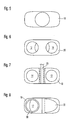
- the inlet adapter is a cast metal part and has two valve seats 20 with which a valve flap 22 cooperate can.
- the valve flap 22 is mounted by means of a valve shaft 23, which with an actuator 24 is connected. If, for example, the valve flap on the Valve seat is present, which is assigned to the heat exchanger channel 12, the flows total exhaust gas flow through the bypass duct 14. There are any Intermediate positions of the valve flap 22 possible to the exhaust gas flow in one split the desired ratio between the two channels.
- the Inlet adapter 18 is welded to the intake manifold 10.
- the bypass channel 14 consists of a bypass tube 26 which is on its Inlet side is welded to the inlet adapter 18. On its outlet side is the bypass tube 26 is welded to an outlet adapter 28.
- the outlet adapter 28 is a stamped and deep-drawn sheet metal part that marks the transition from the two circular cross sections of the heat exchanger channel 12 and Bypass channel 14 on the elongated inlet cross section of the exhaust manifold forms.
- the outlet adapter 28 is welded to the exhaust manifold 16.
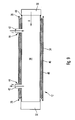
- the heat exchanger channel 12 consists of. an inlet cone 30, one Outlet cone 32 and a heat exchanger tube 34 (see in particular Figure 9).
- the heat exchanger tube 34 is with the inlet cone 30 and the outlet cone 32 welded, which is symbolized here by welds 36.
- a heat exchanger 38 Inside the through the inlet cone 30, the heat exchanger tube 34 and The heat exchanger channel 12 formed in the outlet cone 32 is a heat exchanger 38 arranged, the one in the direction of arrow A from the exhaust gas can be flowed through and on the other hand, symbolized by the two arrows F, from a fluid to allow heat transfer from the exhaust gas to the fluid achieve.
- the internal structure of the heat exchanger 38 is for understanding the Invention of no significance, so that it is not further explained here.
- the outer shell of the heat exchanger is made of metal.
- the heat exchanger 38 is on its inlet side with the inlet cone 30 welded. This is symbolized here by a weld 40. On his On the outlet side, the heat exchanger 38 is loose with a slight radial play inserted into the outlet cone 32. If the heat exchanger 38 and that Extend the heat exchanger tube 34 differently when there are temperature differences, are tensions between the heat exchanger 38 and the heat exchanger tube 34 prevents since the outlet side of the heat exchanger 38 freely in Exhaust cone 32 can move.
- the arrangement of the heat exchanger is comparable to a bridge bearing, in which a fixed bearing and a floating bearing are provided. The fixed bearing is used for positioning, and the floating bearing enables the relative displacements resulting from thermal expansion. In principle, it is of course possible to transfer the heat exchanger to others Way as by a weld in the heat exchanger channel.
- the heat exchanger 38 is provided with two connecting pieces 42 through which Fluid can be supplied to or removed from the heat exchanger 38.
- the two connecting pieces 42 extend through the heat exchanger tube 34 through, for this purpose an elongated hole 44 (see Figure 11) is provided.
- the elongated holes 44 are dimensioned so that the thermal expansion of the heat exchanger 38 are not hindered.
- annular gap 46 Between the outside of the heat exchanger 38 and the inside of the Heat exchanger tube 34, an annular gap 46 is formed. Is in this annular gap a pack or mat 48 is arranged which is made of heat-insulating fiber material consists. The mat 48 is used for heat insulation of the heat exchanger 38. Furthermore it prevents rattling noises that the heat exchanger 38 in the outlet cone 32nd could generate.
- the volume of the heat insulating mat 48 is relative to that Cross-section of the annular gap 46 adjusted so that the mat 48 significantly is compressed. In this way, their gas permeability is reduced that it forms a seal against a potential leakage current from the Outlet side of the heat exchanger 38 through the annular gap between the Heat exchanger and the outlet cone 32 in the annular gap 46 and from there the slots 44 could get outside.
- FIG. 1 A development of the assembly according to the invention is shown in FIG. This is a sealing ring 50 to improve the tightness of the exhaust system provided that between the outlet side of the heat exchanger 38 and the Outlet cone 32 is arranged.
- the sealing ring 50 is selected so that it is on the one hand any leakage current to the annular gap 46 and through the slots 44 into the open prevents, on the other hand, the axial expansion of the heat exchanger 38 and the resulting relative displacement with respect to the outlet cone 32 allows.
- the particular advantage of the assembly according to the invention is on the one hand in that on the one hand they have a very simple structure and result has low manufacturing costs.
- the bypass tube 26 and that Heat exchanger pipe 34 are simple, straight pipe pieces that are standard parts be available.
- the intake manifold 10 and the exhaust manifold 16 can be extruded inexpensively. They are also identical, which is too low Unit costs leads. All constructive details that lead to a high Manufacturing effort lead are combined in a single component, namely in Inlet adapter 18. This ensures, on the one hand, the cross-sectional adjustment of Cross section of the intake manifold 10 to the cross sections of the heat exchanger channel 12 and the bypass channel 14.
- the inlet adapter 18 the flap valve with which the flow distribution through the two channels can be regulated.
- the assembly according to the invention is also distinguished due to the advantageous attachment of the heat exchanger inside the Heat exchanger channel 12 from which thermal stresses are avoided. In combination, there are low manufacturing costs with optimal Mastery of the different thermal expansion behavior of the various components.
Abstract
Description
Die Erfindung betrifft eine Baugruppe bestehend aus Abgas-Wärmetauscher und Bypass, insbesondere für einen sogenannten Zuheizer.The invention relates to an assembly consisting of exhaust gas heat exchanger and bypass, especially for a so-called auxiliary heater.
Ein Zuheizer wird bei Kraftfahrzeugen mit modernen, sparsamen Verbrennungsmotoren verwendet. Diese Motoren produzieren aufgrund ihres hohen Wirkungsgrades nur noch sehr wenig Abwärme, die für das Heizsystem des Kraftfahrzeugs zur Verfügung steht. Die daraus resultierende geringe Heizleistung wird von Fahrzeuginsassen häufig als unkomfortabel empfunden. Daher sind Systeme entwickelt worden, die einen Wärmetauscher im Abgasstrang des Fahrzeugs enthalten. Auf diese Weise kann dem Abgasstrom Wärme entzogen werden, die zum Heizen des Innenraumes des Fahrzeugs verwendet wird.A heater is used in motor vehicles with modern, economical Internal combustion engines used. These engines produce because of their high efficiency only very little waste heat that is needed for the heating system of the Motor vehicle is available. The resulting low heating output is often perceived by vehicle occupants as uncomfortable. Therefore are Systems have been developed that include a heat exchanger in the exhaust system Vehicle included. In this way, heat can be extracted from the exhaust gas flow be used to heat the interior of the vehicle.
Ein solches System weist üblicherweise parallel zu dem durch den Wärmetauscher führenden Strömungsweg einen Bypass auf. Auf diese Weise kann der Wärmetauscher abgeschaltet werden. Dies ist beispielsweise vorteilhaft, wenn unmittelbar nach dem Anlassen des Verbrennungsmotors ein im Abgasstrang angeordneter Katalysator auf seine Betriebstemperatur gebracht werden soll. Dies würde verzögert, wenn das Abgas durch den Wärmetauscher strömt, der eine sehr große Wärmekapazität hat. Such a system usually points parallel to that through the Bypass is carried out by the heat exchanger. In this way the heat exchanger can be switched off. This is advantageous, for example, if immediately after starting the engine in the exhaust system arranged catalyst to be brought to its operating temperature should. This would be delayed if the exhaust gas flows through the heat exchanger has a very large heat capacity.
Bei allen Wärmetauschern im Abgasstrang eines Fahrzeugs stellen sich Probleme, die aus der Wärmedehnung der verschiedenen Bauteile resultieren. Zum einen sind die Bauteile Temperaturunterschieden von mehreren hundert Grad Celsius ausgesetzt. Zum anderen ergibt sich selbst bei einem konstanten Betriebszustand ein starkes Temperaturgefälle zwischen den verschiedenen Bauteilen. Die unterschiedlichen Wärmedehnungen müssen über eine Vielzahl von Betriebszyklen sicher aufgenommen werden, wobei kein Leck im Abgasstrang auftreten darf.With all heat exchangers in the exhaust system of a vehicle Problems that result from the thermal expansion of the various components. On the one hand, the components are temperature differences of several hundred degrees Exposed to Celsius. On the other hand, even with a constant Operating condition a large temperature gradient between the different Components. The different thermal expansions have to be varied of operating cycles are safely recorded, with no leak in the Exhaust system may occur.
Die Aufgabe der Erfindung besteht darin, ein Gehäuse für einen Wärmetauscher zu schaffen, das konstruktiv einfach aufgebaut ist, so daß es kostengünstig hergestellt werden kann, während gleichzeitig die unterschiedlichen Wärmeausdehnungen der verschiedenen Bauteile ermöglicht werden.The object of the invention is to provide a housing for a heat exchanger to create that is structurally simple, so that it can be inexpensively manufactured while maintaining the different Thermal expansion of the various components are made possible.
Zu diesem Zweck ist erfindungsgemäß eine Baugruppe bestehend aus Abgas-Wärmetauscher und Bypass vorgesehen, mit einem Einlaßkrümmer, einem Auslaßkrümmer, einem Kanal für einen Wärmetauscher und einem Bypass-Kanal, wobei sich der Wärmetauscher-Kanal und der Bypass-Kanal parallelgeschaltet zwischen dem Einlaßkrümmer und dem Auslaßkrümmer erstrecken und mit diesem strömungsdicht verbunden sind, wobei im Inneren des Wärmetauscher-Kanals ein Wärmetauscher angeordnet ist, dessen Einlaßseite strömungsdicht mit dem Wärmetauscher-Kanal verbunden ist, wobei die Auslaßseite des Wärmetauschers verschiebbar im Wärmetauscher-Kanal aufgenommen ist, so daß eine Wärmeausdehnung des Wärmetauschers relativ zum Wärmetauscher-Kanal möglich ist. Die erfindungsgemäße Baugruppe beruht auf dem Grundgedanken, einen geschlossenen Kanal für den Abgas-Wärmetauscher vorzusehen. Der Wärmetauscher ist in diesem Kanal an seiner Einlaßseite fest und strömungsdicht angebracht, beispielsweise verschweißt. Auf seiner Auslaßseite ist der Wärmetauscher frei verschiebbar im Wärmetauscher-Kanal aufgenommen. Auf diese Weise kann sich der Wärmetauscher frei im Inneren des Wärmetauscher-Kanals ausdehnen, und Verspannungen aufgrund von unterschiedlichen Wärmeausdehnungen der Bauteile können nicht auftreten. Der außenliegende Kanal sorgt für die notwendige mechanische Stabilität und Dichtigkeit des Abgasstrangs.For this purpose, according to the invention, there is an assembly consisting of an exhaust gas heat exchanger and bypass provided, with an intake manifold, a Exhaust manifold, a channel for a heat exchanger and a bypass channel, the heat exchanger channel and the bypass channel connected in parallel extend between the intake manifold and the exhaust manifold and with this are connected in a fluid-tight manner, being inside the heat exchanger channel a heat exchanger is arranged, the inlet side of which is flow-tight the heat exchanger channel is connected, the outlet side of the Heat exchanger is slidably received in the heat exchanger channel, so that thermal expansion of the heat exchanger relative to the heat exchanger channel is possible. The assembly according to the invention is based on the basic idea to provide a closed channel for the exhaust gas heat exchanger. The The heat exchanger in this duct is fixed and flow-tight on its inlet side attached, for example welded. On its outlet side is the The heat exchanger can be moved freely in the heat exchanger duct. On this way the heat exchanger can move freely inside the heat exchanger duct expand, and tension due to different Thermal expansion of the components cannot occur. The outside The channel ensures the necessary mechanical stability and tightness of the Exhaust line.
Gemäß einer bevorzugten Ausführungsform der Erfindung bestehen der Einlaßkrümmer und der Auslaßkrümmer aus tiefgezogenem oder fließgepreßtem Stahlblech, und sie sind identisch miteinander ausgeführt. Dies führt zu besonders geringen Herstellkosten.According to a preferred embodiment of the invention, the Inlet manifold and the exhaust manifold made of deep-drawn or extruded Sheet steel, and they are identical to each other. This leads to special low manufacturing costs.
Gemäß der bevorzugten Ausführungsform der Erfindung ist vorgesehen, daß zwischen dem Auslaßkrümmer einerseits und dem Bypass-Kanal sowie dem Wärmetauscher-Kanal andererseits ein Auslaßadapter vorgesehen ist. Dieser besteht vorzugsweise aus tiefgezogenem Stahlblech und ist mit dem Auslaßkrümmer verschweißt. Die Verwendung eines Auslaßadapters führt zu vielen Vorteilen bei der Herstellung der Baugruppe. Zum einen können auf diese Weise mit geringem Aufwand die Anschlüsse für den Bypass-Kanal und den Wärmetauscher-Kanal an den Auslaßkrümmer erhalten werden. Ein Auslaßkrümmer, bei dem die Anschlüsse für den Bypass-Kanal sowie den Wärmetauscher-Kanal einstückig ausgebildet wären, wäre nur mit sehr hohem Aufwand herstellbar. Zum anderen ergeben sich Vorteile bei der Montage. Der Auslaßadapter kann mit dem Bypass-Kanal und dem Wärmetauscher-Kanal verschweißt werden, bevor der Auslaßkrümmer aufgesetzt ist. Die entsprechenden Schweißstellen sind somit gut zugänglich, selbst zwischen den beiden Kanälen. Anschließend kann der Auslaßkrümmer auf den Auslaßadapter aufgesetzt und mit diesem verschweißt werden. In diesem Fall ist nur eine umlaufende und außenliegende, also gut erreichbare Schweißnaht auszuführen.According to the preferred embodiment of the invention it is provided that between the exhaust manifold on the one hand and the bypass channel and the Heat exchanger channel on the other hand, an outlet adapter is provided. This consists preferably of deep-drawn sheet steel and is with the Exhaust manifold welded. Using an outlet adapter results in many advantages in the manufacture of the assembly. For one, you can on this Way with little effort the connections for the bypass channel and Heat exchanger duct can be obtained on the exhaust manifold. On Exhaust manifold, in which the connections for the bypass channel and the Heat exchanger channel would be formed in one piece, would only be very high Effort can be made. On the other hand, there are advantages in assembly. The Outlet adapter can be used with the bypass duct and the heat exchanger duct be welded before the exhaust manifold is in place. The corresponding Welds are therefore easily accessible, even between the two channels. Then the exhaust manifold can be placed on the exhaust adapter and with this be welded. In this case, only one circumferential and external, so easily accessible weld.
Vorzugsweise ist ein Einlaßadapter vorgesehen, der zwischen dem Einlaßkrümmer einerseits und dem Bypass-Kanal und dem Wärmetauscher-Kanal andererseits angeordnet ist. Der Einlaßadapter ist vorzugsweise ein Metallgußteil, in das ein Klappenventil integriert ist. Das Klappenventil dient dazu, den Abgasstrom in Abhängigkeit von äußeren Parametern zwischen den beiden Kanälen aufzuteilen. Dabei ist jede beliebige Aufteilung des Volumenstroms zwischen den beiden Kanälen möglich. Der Einlaßadapter bietet den Vorteil, daß alle in der Herstellung aufwendigen Schritte in ein einziges Bauteil integriert sind. Der Einlaßadapter nimmt das Ventil auf, bildet die Ventilsitze für die Ventilklappe und ermöglicht ähnlich wie der Auslaßadapter eine einfache Montage der gesamten Baugruppe.Preferably, an inlet adapter is provided which is between the inlet manifold on the one hand and the bypass duct and the heat exchanger duct on the other hand is arranged. The inlet adapter is preferably a metal casting, in which a flap valve is integrated. The flap valve serves the Exhaust gas flow depending on external parameters between the two Split channels. Here is any division of the volume flow possible between the two channels. The inlet adapter offers the advantage that all steps involved in manufacturing are integrated into a single component. The inlet adapter takes the valve, forms the valve seats for the Valve flap and enables a simple similar to the outlet adapter Assembly of the entire assembly.
Gemäß der bevorzugten Ausführungsform der Erfindung ist vorgesehen, daß der Wärmetauscher-Kanal aus einem Einlaßkonus, einem geraden Wärmetauscher-Rohr und einem Auslaßkonus besteht. Der Wärmetauscher ist an seiner Einlaßseite mit dem Einlaßkonus verschweißt, während die Auslaßseite des Wärmetauschers verschiebbar im Auslaßkonus aufgenommen ist. Das Wärmetauscher-Rohr ist sowohl mit dem Einlaßkonus als auch dem Auslaßkonus verschweißt. Das radiale Spiel zwischen der Auslaßseite des Wärmetauschers und dem Auslaßkonus beträgt in der Größenordnung von 0,2 mm. Dies ermöglicht die Wärmeausdehnung des Wärmetauschers in jeder Richtung, während gleichzeitig ein sehr kleiner Strömungsquerschnitt gebildet ist, der eine Rückströmung des Abgases in den Raum zwischen dem Wärmetauscher-Rohr und dem Wärmetauscher verhindert.According to the preferred embodiment of the invention it is provided that the heat exchanger channel consists of an inlet cone, a straight heat exchanger tube and an outlet cone. The heat exchanger is on his Inlet side welded to the inlet cone, while the outlet side of the Heat exchanger is slidably received in the outlet cone. The heat exchanger tube is with both the inlet cone and the outlet cone welded. The radial play between the outlet side of the heat exchanger and the outlet cone is of the order of 0.2 mm. This enables the Thermal expansion of the heat exchanger in any direction while at the same time a very small flow cross section is formed, which is a backflow of the Exhaust gas in the space between the heat exchanger tube and the Heat exchanger prevented.
Zum Anschließen des Wärmetauschers ist dieser vorzugsweise mit zwei Anschlußstutzen versehen, die sich radial nach außen durch das Wärmetauscher-Rohr hindurch erstrecken. Das Wärmetauscher-Rohr ist zu diesem Zweck mit zwei Löchern versehen, die als Langlöcher ausgeführt sind. Auch dies dient der ungehinderten Wärmeausdehnung des Wärmetauschers.To connect the heat exchanger, this is preferably two Provide connecting pieces that extend radially outwards through the heat exchanger tube extend through. For this purpose, the heat exchanger tube is included two holes that are designed as elongated holes. This also serves unhindered thermal expansion of the heat exchanger.
Zwischen der Innenseite des Wärmetauscher-Rohres und der Außenseite des Wärmetauschers ist ein ringförmiger Spalt vorgesehen. In diesem ist eine Packung aus wärmeisolierendem Fasermaterial angeordnet. Das Material dient zur Wärmeisolierung des Wärmetauschers, so daß Verluste durch Wärmeabstrahlung nach außen reduziert sind. Gleichzeitig ist das wärmeisolierende Material zwischen dem Wärmetauscher und dem Wärmetauscher-Rohr derart komprimiert gehalten, daß es als Abdichtung wirkt. Dies verhindert eine Leckströmung von der Auslaßseite des Wärmetauschers durch den Spalt zwischen dem Auslaßkonus und dem Wärmetauscher in den Ringraum zwischen dem Wärmetauscher und dem Wärmetauscher-Rohr und durch die Langlöcher nach außen. Aufgrund eines Venturi-Effekts im Bereich der Auslaßseite des Wärmetauschers ist eine Leckströmung hin zu den Langlöchem im Wärmetauscher-Rohr aber ohnehin nicht oder nur in sehr geringem Umfang zu erwarten; es ist eher wahrscheinlich, daß in diesem Bereich Außenluft angesaugt wird.Between the inside of the heat exchanger tube and the outside of the An annular gap is provided for the heat exchanger. In this is a pack arranged from heat-insulating fiber material. The material is used for Thermal insulation of the heat exchanger, so that losses due to heat radiation are reduced to the outside. At the same time is the heat insulating material compressed between the heat exchanger and the heat exchanger tube held that it acts as a seal. This prevents leakage from the Outlet side of the heat exchanger through the gap between the outlet cone and the heat exchanger in the annular space between the heat exchanger and the Heat exchanger tube and through the elongated holes to the outside. Because of a Venturi effect in the area of the outlet side of the heat exchanger is one Leakage flow to the elongated holes in the heat exchanger tube anyway not to be expected or only to a very small extent; it's more likely that outside air is drawn in in this area.
Gemäß einer Weiterbildung der Erfindung kann vorgesehen sein, daß zwischen der Auslaßseite des Wärmetauschers und dem Auslaßkonus eine Schiebedichtung angeordnet ist, die jegliche Leckströmung hin zu den Langlöchern im Rohr zuverlässig verhindert.According to a development of the invention, it can be provided that one between the outlet side of the heat exchanger and the outlet cone Sliding seal is arranged that any leakage flow towards the elongated holes reliably prevented in the pipe.
Vorteilhafte Ausgestaltungen der Erfindung ergeben sich aus den Unteransprüchen.Advantageous embodiments of the invention result from the subclaims.
Die Erfindung wird nachfolgend anhand einer bevorzugten Ausführungsform beschrieben, die in den beigefügten Zeichnungen dargestellt ist. In diesen zeigen:
- Figur 1 eine Seitenansicht einer erfindungsgemäßen Baugruppe;
- Figur 2 eine Draufsicht auf die erfindungsgemäße Baugruppe;
- Figur 3 eine Schnittansicht entlang der Ebene III-III von Figur 1;
- Figur 4 die Schnittansicht von Figur 3 in vergrößertem Maßstab;
- Figur 5 einen Schnitt entlang der Ebene V-V von Figur 4;
- Figur 6 einen Schnitt entlang der Ebene VI-VI von Figur 4;
- Figur 7 einen Schnitt entlang der Ebene VII-VII von Figur 4;
- Figur 8 einen Schnitt entlang der Ebene VIII-VIII von Figur 4;
- Figur 9 einen Schnitt entlang der Ebene IX-IX von Figur 4;
Figur 10 eine abgebrochene Ansicht entsprechend derjenigen von Figur 9, wobei eine Ausführungsvariante gezeigt ist; undFigur 11 eine Draufsicht auf die Auslaßseite des Wärmetauscher-Kanals.
- Figure 1 is a side view of an assembly according to the invention;
- Figure 2 is a plan view of the assembly according to the invention;
- Figure 3 is a sectional view taken along the plane III-III of Figure 1;
- Figure 4 shows the sectional view of Figure 3 on an enlarged scale;
- 5 shows a section along the plane VV of Figure 4;
- 6 shows a section along the plane VI-VI of Figure 4;
- 7 shows a section along the plane VII-VII of Figure 4;
- Figure 8 is a section along the plane VIII-VIII of Figure 4;
- Figure 9 is a section along the plane IX-IX of Figure 4;
- Figure 10 is a broken away view corresponding to that of Figure 9, showing an embodiment; and
- Figure 11 is a plan view of the outlet side of the heat exchanger channel.
In den Figuren 1 bis 3 ist eine Baugruppe mit einem Abgas-Wärmetauscher und einem Bypass gezeigt. Sie ist dafür vorgesehen, im Abgasstrang eines Fahrzeugs angeordnet zu werden, wobei sie in der Richtung des Pfeils von Figur 1 durchströmt wird, also bezüglich Figur 1 von rechts nach links.In Figures 1 to 3 is an assembly with an exhaust gas heat exchanger and a bypass. It is intended for one in the exhaust system To be arranged vehicle, in the direction of the arrow of Figure 1 is flowed through, ie with respect to Figure 1 from right to left.
Die Baugruppe weist einen Einlaßkrümmer 10 auf, der aus tiefgezogenem
oder fließgepreßtem Stahlblech besteht. Der Einlaßkrümmer ermöglicht grundsätzlich,
den Abgasstrom zwischen einem Wärmetauscher-Kanal 12 und einem
Bypass-Kanal 14 aufzuteilen. Der Wärmetauscher-Kanal und der Bypass-Kanal
werden stromabwärts von einem Auslaßkrümmer 16 wieder zusammengefaßt. Der
Auslaßkrümmer ist identisch mit dem Einlaßkrümmer 10 ausgebildet.The assembly has an
Auf der Auslaßseite des Einlaßkrümmers 10 ist ein Einlaßadapter 18 (siehe
auch die Figuren 4, 7 und 8) angeordnet. Der Einlaßadapter ist ein Metallgußteil
und weist zwei Ventilsitze 20 auf, mit denen eine Ventilklappe 22 zusammenwirken
kann. Die Ventilklappe 22 ist mittels einer Ventilwelle 23 gelagert, die mit
einem Stellmotor 24 verbunden ist. Wenn die Ventilklappe beispielsweise an dem
Ventilsitz anliegt, der dem Wärmetauscher-Kanal 12 zugeordnet ist, strömt der
gesamte Abgasstrom durch den Bypass-Kanal 14. Es sind beliebige
Zwischenstellungen der Ventilklappe 22 möglich, um den Abgasstrom in einem
jeweils gewünschten Verhältnis zwischen den beiden Kanälen aufzuteilen. Der
Einlaßadapter 18 ist mit dem Einlaßkrümmer 10 verschweißt.On the outlet side of the
Der Bypass-Kanal 14 besteht aus einem Bypass-Rohr 26, das auf seiner
Einlaßseite mit dem Einlaßadapter 18 verschweißt ist. Auf seiner Auslaßseite ist
das Bypass-Rohr 26 mit einem Auslaß-Adapter 28 verschweißt. Der Auslaßadapter
28 ist ein gestanztes und tiefgezogenes Blechteil, das den Übergang von
den beiden kreisförmigen Querschnitten des Wärmetauscher-Kanals 12 und des
Bypass-Kanals 14 auf den langgestreckten Einlaßquerschnitt des Auslaßkrümmers
bildet. Der Auslaßadapter 28 ist mit dem Auslaßkrümmer 16 verschweißt. The
Der Wärmetauscher-Kanal 12 besteht aus. einem Einlaßkonus 30, einem
Auslaßkonus 32 und einem Wärmetauscher-Rohr 34 (siehe insbesondere Figur 9).
Das Wärmetauscher-Rohr 34 ist mit dem Einlaßkonus 30 und dem Auslaßkonus
32 verschweißt, was hier durch Schweißnähte 36 symbolisiert ist.The
Im Inneren des durch den Einlaßkonus 30, das Wärmetauscher-Rohr 34 und
den Auslaßkonus 32 gebildeten Wärmetauscher-Kanals 12 ist ein Wärmetauscher
38 angeordnet, der zum einen in der Richtung des Pfeils A vom Abgas
durchströmt werden kann und zum anderen, symbolisiert durch die beiden Pfeile
F, von einem Fluid, um eine Wärmeübertragung vom Abgas zum Fluid zu
erzielen. Der Innenaufbau des Wärmetauschers 38 ist für das Verständnis der
Erfindung ohne Bedeutung, so daß er hier nicht weiter erläutert wird. Die
Außenhülle des Wärmetauschers besteht aus Metall.Inside the through the
Der Wärmetauscher 38 ist auf seiner Einlaßseite mit dem Einlaßkonus 30
verschweißt. Dies wird hier symbolisiert durch eine Schweißnaht 40. Auf seiner
Auslaßseite ist der Wärmetauscher 38 mit einem geringfügigen radialen Spiel lose
in den Auslaßkonus 32 eingesetzt. Sofern sich der Wärmetauscher 38 und das
Wärmetauscher-Rohr 34 bei Temperaturunterschieden unterschiedlich ausdehnen,
sind Verspannungen zwischen dem Wärmetauscher 38 und dem Wärmetauscher-Rohr
34 verhindert, da sich die Auslaßseite des Wärmetauschers 38 frei im
Auslaßkonus 32 verschieben kann. Die Anordnung des Wärmetauschers ist
vergleichbar mit einer Brückenlagerung, bei der ein Festlager und ein Loslager
vorgesehen sind. Das Festlager dient zur Positionierung, und das Loslager
ermöglicht die von Wärmeausdehnungen resultierenden Relativverschiebungen.
Dabei ist es grundsätzlich natürlich möglich, den Wärmetauscher auf andere
Weise als durch eine Schweißnaht im Wärmetauscher-Kanal festzulegen.The
Der Wärmetauscher 38 ist mit zwei Anschlußstutzen 42 versehen, durch die
Fluid zum Wärmetauscher 38 zugeführt bzw. von diesem abgeführt werden kann.
Die beiden Anschlußstutzen 42 erstrecken sich durch das Wärmetauscher-Rohr 34
hindurch, wobei zu diesem Zweck jeweils ein Langloch 44 (siehe Figur 11)
vorgesehen ist. Die Langlöcher 44 sind so dimensioniert, daß die Wärmeausdehnungen
des Wärmetauschers 38 nicht behindert werden.The
Zwischen der Außenseite des Wärmetauschers 38 und der Innenseite des
Wärmetauscher-Rohres 34 ist ein Ringspalt 46 gebildet. In diesem Ringspalt ist
eine Packung oder Matte 48 angeordnet, die aus wärmeisolierendem Fasermaterial
besteht. Die Matte 48 dient zur Wärmeisolierung des Wärmetauschers 38. Ferner
verhindert sie Klappergeräusche, die der Wärmetauscher 38 im Auslaßkonus 32
erzeugen könnte.Between the outside of the
Das Volumen der wärmeisolierenden Matte 48 ist in bezug auf den
Querschnitt des Ringspaltes 46 so abgestimmt, daß die Matte 48 erheblich
komprimiert wird. Auf diese Weise verringert sich ihre Gasdurchlässigkeit derart,
daß sie eine Abdichtung gegen einen potentiellen Leckstrom bildet, der von der
Auslaßseite des Wärmetauschers 38 durch den Ringspalt zwischen dem
Wärmetauscher und dem Auslaßkonus 32 in den Ringspalt 46 und von dort durch
die Langlöcher 44 ins Freie gelangen könnte.The volume of the
In Figur 10 ist eine Weiterbildung der erfindungsgemäßen Baugruppe gezeigt.
Bei dieser ist zur Verbesserung der Dichtigkeit der Abgasanlage ein Dichtring 50
vorgesehen, der zwischen der Auslaßseite des Wärmetauschers 38 und dem
Auslaßkonus 32 angeordnet ist. Der Dichtring 50 ist so gewählt, daß er einerseits
jeglichen Leckstrom hin zum Ringspalt 46 und durch die Langlöcher 44 ins Freie
verhindert, andererseits weiterhin die axiale Ausdehnung des Wärmetauschers 38
und die daraus resultierende Relativverschiebung gegenüber dem Auslaßkonus 32
ermöglicht.A development of the assembly according to the invention is shown in FIG.
This is a sealing
Der besondere Vorteil der erfindungsgemäßen Baugruppe besteht zum einen
darin, daß sie zum einen einen sehr einfachen Aufbau und daraus resultierend
geringe Herstellungskosten aufweist. Das Bypass-Rohr 26 und das
Wärmetauscher-Rohr 34 sind einfache, gerade Rohrstücke, die als Standardteile
zur Verfügung stehen. Der Einlaßkrümmer 10 und der Auslaßkrümmer 16 können
kostengünstig fließgepreßt werden. Außerdem sind sie identisch, was zu niedrigen
Stückkosten führt. Alle konstruktiven Details, die zu einem hohen
Herstellungsaufwand führen, sind in einem einzigen Bauteil vereint, nämlich im
Einlaßadapter 18. Dieser gewährleistet zum einen die Querschnittsanpassung vom
Querschnitt des Einlaßkrümmers 10 auf die Querschnitte des Wärmetauscher-Kanals
12 und des Bypass-Kanals 14. Zum anderen nimmt der Einlaßadapter 18
das Klappenventil auf, mit dem die Strömungsverteilung durch die beiden Kanäle
geregelt werden kann. Die erfindungsgemäße Baugruppe zeichnet sich außerdem
durch die vorteilhafte Anbringung des Wärmetauschers im Inneren des
Wärmetauscher-Kanals 12 aus, durch die Wärmespannungen vermieden werden.
In Kombination ergeben sich geringe Herstellungskosten bei optimaler
Beherrschung des unterschiedlichen Wärmeausdehnungsverhaltens der
verschiedenen Bauteile. The particular advantage of the assembly according to the invention is on the one hand
in that on the one hand they have a very simple structure and result
has low manufacturing costs. The
- 10:10:
- Einlaßkrümmerintake manifold
- 12:12:
- Wärmetauscher-KanalHeat exchanger duct
- 14:14:
- Bypass-KanalBypass channel
- 16:16:
- Auslaßkrümmerexhaust manifold
- 18:18:
- Einlaßadapterinlet adapter
- 20:20:
- Ventilsitzvalve seat
- 22:22:
- Ventilklappevalve flap
- 23:23:
- Ventilwellevalve shaft
- 24:24:
- Stellmotorservomotor
- 26:26:
- Bypass-RohrBypass pipe
- 28:28:
- Auslaßadapteroutlet adapter
- 30:30:
- Einlaßkonusintake cone
- 32:32:
- Auslaßkonusoutlet cone
- 34:34:
- Wärmetauscher-RohrHeat exchanger tube
- 36:36:
- SchweißnahtWeld
- 38:38:
- Wärmetauscherheat exchangers
- 40:40:
- SchweißnahtWeld
- 42:42:
- Anschlußstutzenconnecting branch
- 44:44:
- LanglochLong hole
- 46:46:
- Ringspaltannular gap
- 48:48:
- wärmeisolierende Matteheat insulating mat
- 50:50:
- Dichtungpoetry
Claims (22)
Applications Claiming Priority (2)
| Application Number | Priority Date | Filing Date | Title |
|---|---|---|---|
| DE10303910 | 2003-01-31 | ||
| DE10303910A DE10303910A1 (en) | 2003-01-31 | 2003-01-31 | Assembly consisting of exhaust gas heat exchanger and bypass |
Publications (2)
| Publication Number | Publication Date |
|---|---|
| EP1443186A1 true EP1443186A1 (en) | 2004-08-04 |
| EP1443186B1 EP1443186B1 (en) | 2005-12-21 |
Family
ID=32603069
Family Applications (1)
| Application Number | Title | Priority Date | Filing Date |
|---|---|---|---|
| EP04001668A Expired - Lifetime EP1443186B1 (en) | 2003-01-31 | 2004-01-27 | Assembly comprising an exhaust gas heat exchanger and bypass |
Country Status (5)
| Country | Link |
|---|---|
| US (1) | US7264040B2 (en) |
| EP (1) | EP1443186B1 (en) |
| AT (1) | ATE313705T1 (en) |
| DE (2) | DE10303910A1 (en) |
| ES (1) | ES2254996T3 (en) |
Cited By (8)
| Publication number | Priority date | Publication date | Assignee | Title |
|---|---|---|---|---|
| FR2905978A1 (en) * | 2006-09-15 | 2008-03-21 | Faurecia Sys Echappement | Exhaust element for heat combustion engine of e.g. minivan, has valve with input connected to upstream pipe, and compensating unit formed by bypass pipe`s portion and compensating dilation difference between exchanger`s pipe and bypass pipe |
| DE102005039794B4 (en) * | 2005-08-22 | 2010-06-10 | J. Eberspächer GmbH & Co. KG | Exhaust gas heat exchanger |
| EP2295921A2 (en) * | 2009-07-30 | 2011-03-16 | Behr GmbH & Co. KG | Heat exchanger comprising connecting section with sealing and tensioning surface |
| ITBO20100474A1 (en) * | 2010-07-27 | 2012-01-28 | Magneti Marelli Spa | SILENCER WITH INTEGRATED HEAT EXCHANGER |
| CN101809260B (en) * | 2007-10-10 | 2012-04-18 | 洋马株式会社 | Engine exhaust heat recovery device and energy supply device using the same |
| DE102012204126A1 (en) * | 2012-03-15 | 2013-09-19 | Eberspächer Exhaust Technology GmbH & Co. KG | Steam generator for a Rankine process |
| DE102012104396B4 (en) * | 2012-05-22 | 2015-12-31 | Tenneco Gmbh | Automobile mufflers |
| WO2018103898A1 (en) * | 2016-12-09 | 2018-06-14 | Faurecia Systemes D'echappement | Exhaust heat recuperation device, with improved sealing |
Families Citing this family (34)
| Publication number | Priority date | Publication date | Assignee | Title |
|---|---|---|---|---|
| US7353865B2 (en) * | 2003-09-05 | 2008-04-08 | Arvinmeritor Technology, Llc | Method for controlling a valve for an exhaust system |
| DE502004011048D1 (en) * | 2003-10-02 | 2010-05-27 | Behr Gmbh & Co Kg | CHARGER OF A MOTOR VEHICLE |
| US8118082B2 (en) | 2004-05-07 | 2012-02-21 | Behr Gmbh & Co. Kg | Heat exchanger in particular for exhaust coolers on internal combustion engines |
| DE102004055086A1 (en) * | 2004-11-15 | 2006-05-18 | Behr Gmbh & Co. Kg | Metallic collecting box for a heat exchanger, in particular for motor vehicles |
| DE102004061400B4 (en) * | 2004-12-21 | 2012-12-20 | Umicore Ag & Co. Kg | Method for generating a stream of hot combustion gases with adjustable temperature, apparatus for carrying out the method and use of the combustion gases for the targeted aging of catalysts |
| SE528197C2 (en) * | 2005-02-17 | 2006-09-26 | Scania Cv Ab | Intercooler |
| US20070089412A1 (en) * | 2005-10-22 | 2007-04-26 | Arnd Sommerhoff | Method for controlling an exhaust gas recirculation system |
| US7610949B2 (en) * | 2006-11-13 | 2009-11-03 | Dana Canada Corporation | Heat exchanger with bypass |
| US8794299B2 (en) * | 2007-02-27 | 2014-08-05 | Modine Manufacturing Company | 2-Pass heat exchanger including thermal expansion joints |
| DE102007048824B4 (en) * | 2007-10-10 | 2018-02-22 | Mahle International Gmbh | Heat exchanger, in particular for exhaust gas cooling |
| FR2923859B1 (en) * | 2007-11-15 | 2009-12-18 | Valeo Systemes Thermiques Branche Thermique Habitacle | HEAT EXCHANGER FOR AN AIR SUPPLY CIRCUIT FOR A MOTOR VEHICLE ENGINE |
| GB0813938D0 (en) * | 2008-07-30 | 2008-09-03 | Heat Recovery Solutions Ltd | Heat exchanger |
| DE102008051268A1 (en) * | 2008-10-10 | 2010-04-15 | Mahle International Gmbh | cooling device |
| US9664087B2 (en) * | 2010-07-22 | 2017-05-30 | Wescast Industries, Inc. | Exhaust heat recovery system with bypass |
| WO2013033839A1 (en) | 2011-09-09 | 2013-03-14 | Dana Canada Corporation | Stacked plate exhaust gas recovery device |
| JP2014034922A (en) * | 2012-08-08 | 2014-02-24 | Suzuki Motor Corp | Exhaust heat recovery device |
| US9989322B2 (en) * | 2013-03-01 | 2018-06-05 | Dana Canada Corporation | Heat recovery device with improved lightweight flow coupling chamber and insertable valve |
| EP2772620A1 (en) | 2013-03-01 | 2014-09-03 | Borgwarner Inc. | Heat recovery device |
| EP2803843B1 (en) | 2013-05-14 | 2018-02-14 | Bosal Emission Control Systems NV | Unit for recovering thermal energy from exhaust gas of an internal combustion engine |
| GB2530897B (en) * | 2013-06-20 | 2016-11-02 | Boustead Int Heaters Ltd | Improvements in waste heat recovery units |
| FR3013823B1 (en) * | 2013-11-28 | 2018-09-21 | F2A - Fabrication Aeraulique Et Acoustique | DOUBLE FLOW AIR / AIR EXCHANGER, AIR TREATMENT PLANT AND METHOD FOR CLEANING SUCH EXCHANGER |
| WO2016032808A1 (en) * | 2014-08-27 | 2016-03-03 | Borgwarner Inc. | Expanded function exhaust heat exchanger |
| ES2696980T3 (en) | 2015-09-14 | 2019-01-21 | Bosal Emission Control Systems Nv | Component of heat recovery for an exhaust system of an internal combustion engine |
| DE102016109247B4 (en) * | 2016-05-19 | 2020-03-26 | Benteler Automobiltechnik Gmbh | Exhaust gas heat exchanger |
| DE102016213386A1 (en) * | 2016-07-21 | 2018-01-25 | Ford Global Technologies, Llc | Internal combustion engine with turbocharging and method for operating such an internal combustion engine |
| EP3339618A1 (en) * | 2016-12-20 | 2018-06-27 | Borgwarner Emissions Systems Spain, S.L.U. | Valve for building a compact heat recovery unit |
| JP6805987B2 (en) * | 2017-07-10 | 2020-12-23 | トヨタ自動車株式会社 | Exhaust heat recovery structure |
| CN107388859B (en) * | 2017-09-07 | 2023-06-02 | 华中科技大学 | Heat exchanger assembly and self-adjusting flow heat exchanger |
| US20190255912A1 (en) * | 2018-02-19 | 2019-08-22 | Ford Global Technologies, Llc | Cabin heating system with sealed heat transfer loop |
| US20190255913A1 (en) * | 2018-02-19 | 2019-08-22 | Ford Global Technologies, Llc | System and method for heating a cabin of a motor vehicle |
| US11022069B2 (en) | 2018-12-07 | 2021-06-01 | Tenneco Automotive Operating Company Inc. | Exhaust gas heat recovery system |
| US11041459B2 (en) * | 2018-12-07 | 2021-06-22 | Tenneco Automotive Operating Company Inc. | Exhaust gas heat recovery system |
| DE102019107792A1 (en) * | 2019-03-26 | 2020-10-01 | Faurecia Emissions Control Technologies, Germany Gmbh | Modular system for exhaust heat recovery devices, tubular adapter for a modular system and vehicle |
| DE102021111717A1 (en) | 2021-05-05 | 2022-11-10 | Faurecia Emissions Control Technologies, Germany Gmbh | Heat recovery assembly for an exhaust system and exhaust system |
Citations (6)
| Publication number | Priority date | Publication date | Assignee | Title |
|---|---|---|---|---|
| DE29714478U1 (en) * | 1997-08-13 | 1997-10-09 | Gillet Heinrich Gmbh | Heat exchangers in exhaust systems of internal combustion engines |
| DE29611034U1 (en) * | 1996-06-12 | 1997-10-16 | Hohenberger Ralph | Arrangement for dissipating the heat loss of an internal combustion engine |
| US6141961A (en) * | 1998-03-11 | 2000-11-07 | Ecia-Equipments Et Composants Pour L'industrie Automobile | Exhaust element with heat exchanger |
| CA2273698A1 (en) * | 1999-06-06 | 2000-12-08 | Easton Bennett | Heat exchanger for motor vehicle exhaust |
| WO2001050047A1 (en) * | 1999-12-29 | 2001-07-12 | Ford Motor Company | Exhaust valve for combustion engines |
| US20030015184A1 (en) * | 2001-07-18 | 2003-01-23 | Cooper-Standard Automotive (Deutschland) Gmbh | Cooler of an exhaust gas recirculation system and exhaust gas recirculation system including one such cooler |
Family Cites Families (10)
| Publication number | Priority date | Publication date | Assignee | Title |
|---|---|---|---|---|
| US1539267A (en) * | 1923-03-29 | 1925-05-26 | Schutte & Koerting Co | Heat-exchange apparatus |
| US3751917A (en) * | 1970-10-24 | 1973-08-14 | Alfa Romeo Spa | Exhaust chamber for a motor vehicle provided with an internal combustion engine |
| DE2128990A1 (en) * | 1971-06-11 | 1973-01-04 | Volkswagenwerk Ag | CONVERTER FOR CATALYTIC EXHAUST GAS CLEANING |
| NO164128C (en) * | 1988-04-29 | 1990-08-29 | Telavaag Energiteknikk A S | HEAT EXCHANGE ASSOCIATED WITH A WATER DRAINAGE PIPE. |
| JPH0730213Y2 (en) * | 1988-11-17 | 1995-07-12 | 川崎重工業株式会社 | Heat exchanger |
| GB9812238D0 (en) * | 1998-06-08 | 1998-08-05 | Schack Engineering Gb Limited | Heat exchanger |
| GB0001283D0 (en) * | 2000-01-21 | 2000-03-08 | Serck Heat Transfer Limited | Twin flow valve gas cooler |
| GB0018406D0 (en) * | 2000-07-28 | 2000-09-13 | Serck Heat Transfer Limited | EGR bypass tube cooler |
| US6729122B2 (en) * | 2001-09-07 | 2004-05-04 | Honda Giken Kogyo Kabushiki Kaisha | Exhaust gas purification system of internal combustion engines |
| EP1467082B1 (en) * | 2002-01-16 | 2016-03-30 | Mitsubishi Denki Kabushiki Kaisha | Exhaust gas recirculating device |
-
2003
- 2003-01-31 DE DE10303910A patent/DE10303910A1/en not_active Withdrawn
-
2004
- 2004-01-27 AT AT04001668T patent/ATE313705T1/en not_active IP Right Cessation
- 2004-01-27 DE DE502004000186T patent/DE502004000186D1/en not_active Expired - Lifetime
- 2004-01-27 ES ES04001668T patent/ES2254996T3/en not_active Expired - Lifetime
- 2004-01-27 EP EP04001668A patent/EP1443186B1/en not_active Expired - Lifetime
- 2004-01-30 US US10/769,620 patent/US7264040B2/en active Active
Patent Citations (6)
| Publication number | Priority date | Publication date | Assignee | Title |
|---|---|---|---|---|
| DE29611034U1 (en) * | 1996-06-12 | 1997-10-16 | Hohenberger Ralph | Arrangement for dissipating the heat loss of an internal combustion engine |
| DE29714478U1 (en) * | 1997-08-13 | 1997-10-09 | Gillet Heinrich Gmbh | Heat exchangers in exhaust systems of internal combustion engines |
| US6141961A (en) * | 1998-03-11 | 2000-11-07 | Ecia-Equipments Et Composants Pour L'industrie Automobile | Exhaust element with heat exchanger |
| CA2273698A1 (en) * | 1999-06-06 | 2000-12-08 | Easton Bennett | Heat exchanger for motor vehicle exhaust |
| WO2001050047A1 (en) * | 1999-12-29 | 2001-07-12 | Ford Motor Company | Exhaust valve for combustion engines |
| US20030015184A1 (en) * | 2001-07-18 | 2003-01-23 | Cooper-Standard Automotive (Deutschland) Gmbh | Cooler of an exhaust gas recirculation system and exhaust gas recirculation system including one such cooler |
Cited By (13)
| Publication number | Priority date | Publication date | Assignee | Title |
|---|---|---|---|---|
| DE102005039794B4 (en) * | 2005-08-22 | 2010-06-10 | J. Eberspächer GmbH & Co. KG | Exhaust gas heat exchanger |
| FR2905978A1 (en) * | 2006-09-15 | 2008-03-21 | Faurecia Sys Echappement | Exhaust element for heat combustion engine of e.g. minivan, has valve with input connected to upstream pipe, and compensating unit formed by bypass pipe`s portion and compensating dilation difference between exchanger`s pipe and bypass pipe |
| CN101809260B (en) * | 2007-10-10 | 2012-04-18 | 洋马株式会社 | Engine exhaust heat recovery device and energy supply device using the same |
| EP2295921A2 (en) * | 2009-07-30 | 2011-03-16 | Behr GmbH & Co. KG | Heat exchanger comprising connecting section with sealing and tensioning surface |
| EP2295921B1 (en) | 2009-07-30 | 2019-01-16 | MAHLE Behr GmbH & Co. KG | Heat exchanger comprising connecting section with sealing and tensioning surface |
| EP2295921A3 (en) * | 2009-07-30 | 2015-02-25 | Behr GmbH & Co. KG | Heat exchanger comprising connecting section with sealing and tensioning surface |
| US8397863B2 (en) | 2010-07-27 | 2013-03-19 | MAGNETI MARELLI S.p.A. | Muffler with a built-in heat exchanger |
| EP2412945A3 (en) * | 2010-07-27 | 2012-04-11 | Magneti Marelli S.p.A. | Muffler with a built-in heat exchanger |
| ITBO20100474A1 (en) * | 2010-07-27 | 2012-01-28 | Magneti Marelli Spa | SILENCER WITH INTEGRATED HEAT EXCHANGER |
| DE102012204126A1 (en) * | 2012-03-15 | 2013-09-19 | Eberspächer Exhaust Technology GmbH & Co. KG | Steam generator for a Rankine process |
| DE102012104396B4 (en) * | 2012-05-22 | 2015-12-31 | Tenneco Gmbh | Automobile mufflers |
| WO2018103898A1 (en) * | 2016-12-09 | 2018-06-14 | Faurecia Systemes D'echappement | Exhaust heat recuperation device, with improved sealing |
| FR3060053A1 (en) * | 2016-12-09 | 2018-06-15 | Faurecia Systemes D'echappement | HEAT RECOVERY DEVICE WITH EXHAUST, IMPROVED SEALING |
Also Published As
| Publication number | Publication date |
|---|---|
| DE10303910A1 (en) | 2004-08-12 |
| ES2254996T3 (en) | 2006-06-16 |
| DE502004000186D1 (en) | 2006-01-26 |
| EP1443186B1 (en) | 2005-12-21 |
| US7264040B2 (en) | 2007-09-04 |
| ATE313705T1 (en) | 2006-01-15 |
| US20040251012A1 (en) | 2004-12-16 |
Similar Documents
| Publication | Publication Date | Title |
|---|---|---|
| EP1443186B1 (en) | Assembly comprising an exhaust gas heat exchanger and bypass | |
| DE10061846B4 (en) | Exhaust gas turbocharger for an internal combustion engine | |
| DE10022052C2 (en) | Turbine housing for exhaust gas turbochargers | |
| EP1812698B1 (en) | Exhaust-gas turbocharger for an internal combustion engine | |
| DE102008047448A1 (en) | turbocharger | |
| DE10321638A1 (en) | Switchable waste gas exchanger for e.g. exhaust gas recirculation lines in vehicle engines, switching valve operation is controlled according to coolant fluid temperature | |
| DE202011110189U1 (en) | Silencer with built-in heat exchanger | |
| EP1895258A2 (en) | Heat exchange apparatus | |
| DE10360645A1 (en) | exhaust | |
| DE112011102910T5 (en) | turbocharger | |
| EP3452702B1 (en) | Turbine housing for a turbocharger of an internal combustion engine, and turbocharger | |
| DE102008029455A1 (en) | Heat exchanger i.e. charge-air cooler, for use in motor vehicle, has distributor and collecting chambers, cooling pipes and walls that are made from plastic, where heat exchanger is integrated into cylinder-head cover blown by air flow | |
| DE10041579A1 (en) | Valve arrangement with double flap and thermal bridge for an exhaust gas recirculation system and method for its operation | |
| DE102015009501A1 (en) | Engine cooling | |
| DE102007048824B4 (en) | Heat exchanger, in particular for exhaust gas cooling | |
| DE102014015072A1 (en) | Air gap insulated exhaust manifold and method of making an air gap isolated exhaust manifold | |
| WO2008058737A1 (en) | Exhaust-gas recirculation device | |
| EP2194245A2 (en) | Oil-waste gas cooling module for a combustion machine | |
| DE102014114002A1 (en) | exhaust manifold | |
| EP2886991A1 (en) | Heat exchanger | |
| DE10121498A1 (en) | Exhaust gas system for internal combustion engine has double-shell manifold with pipe connector formed on outer shell for tapping of exhaust gas for exhaust gas recirculation from insulating space between inner and outer shells | |
| DE102019202380A1 (en) | Internal combustion engine with an exhaust manifold and an exhaust gas turbocharger | |
| EP2961957B1 (en) | Air intake | |
| DE102017220231B3 (en) | Internal combustion engine | |
| DE102014222158A1 (en) | Exhaust gas heat exchanger |
Legal Events
| Date | Code | Title | Description |
|---|---|---|---|
| PUAI | Public reference made under article 153(3) epc to a published international application that has entered the european phase |
Free format text: ORIGINAL CODE: 0009012 |
|
| AK | Designated contracting states |
Kind code of ref document: A1 Designated state(s): AT BE BG CH CY CZ DE DK EE ES FI FR GB GR HU IE IT LI LU MC NL PT RO SE SI SK TR |
|
| AX | Request for extension of the european patent |
Extension state: AL LT LV MK |
|
| 17P | Request for examination filed |
Effective date: 20050131 |
|
| 17Q | First examination report despatched |
Effective date: 20050228 |
|
| AKX | Designation fees paid |
Designated state(s): AT BE BG CH CY CZ DE DK EE ES FI FR GB GR HU IE IT LI LU MC NL PT RO SE SI SK TR |
|
| RAP1 | Party data changed (applicant data changed or rights of an application transferred) |
Owner name: ARVIN TECHNOLOGIES, INC. |
|
| GRAP | Despatch of communication of intention to grant a patent |
Free format text: ORIGINAL CODE: EPIDOSNIGR1 |
|
| GRAS | Grant fee paid |
Free format text: ORIGINAL CODE: EPIDOSNIGR3 |
|
| GRAA | (expected) grant |
Free format text: ORIGINAL CODE: 0009210 |
|
| AK | Designated contracting states |
Kind code of ref document: B1 Designated state(s): AT BE BG CH CY CZ DE DK EE ES FI FR GB GR HU IE IT LI LU MC NL PT RO SE SI SK TR |
|
| PG25 | Lapsed in a contracting state [announced via postgrant information from national office to epo] |
Ref country code: FI Free format text: LAPSE BECAUSE OF FAILURE TO SUBMIT A TRANSLATION OF THE DESCRIPTION OR TO PAY THE FEE WITHIN THE PRESCRIBED TIME-LIMIT Effective date: 20051221 Ref country code: IE Free format text: LAPSE BECAUSE OF FAILURE TO SUBMIT A TRANSLATION OF THE DESCRIPTION OR TO PAY THE FEE WITHIN THE PRESCRIBED TIME-LIMIT Effective date: 20051221 Ref country code: NL Free format text: LAPSE BECAUSE OF FAILURE TO SUBMIT A TRANSLATION OF THE DESCRIPTION OR TO PAY THE FEE WITHIN THE PRESCRIBED TIME-LIMIT Effective date: 20051221 Ref country code: SI Free format text: LAPSE BECAUSE OF FAILURE TO SUBMIT A TRANSLATION OF THE DESCRIPTION OR TO PAY THE FEE WITHIN THE PRESCRIBED TIME-LIMIT Effective date: 20051221 Ref country code: SK Free format text: LAPSE BECAUSE OF FAILURE TO SUBMIT A TRANSLATION OF THE DESCRIPTION OR TO PAY THE FEE WITHIN THE PRESCRIBED TIME-LIMIT Effective date: 20051221 Ref country code: RO Free format text: LAPSE BECAUSE OF FAILURE TO SUBMIT A TRANSLATION OF THE DESCRIPTION OR TO PAY THE FEE WITHIN THE PRESCRIBED TIME-LIMIT Effective date: 20051221 |
|
| REG | Reference to a national code |
Ref country code: GB Ref legal event code: FG4D Free format text: NOT ENGLISH |
|
| REG | Reference to a national code |
Ref country code: CH Ref legal event code: EP |
|
| REG | Reference to a national code |
Ref country code: IE Ref legal event code: FG4D Free format text: LANGUAGE OF EP DOCUMENT: GERMAN |
|
| PGFP | Annual fee paid to national office [announced via postgrant information from national office to epo] |
Ref country code: CZ Payment date: 20060126 Year of fee payment: 3 |
|
| REF | Corresponds to: |
Ref document number: 502004000186 Country of ref document: DE Date of ref document: 20060126 Kind code of ref document: P |
|
| PG25 | Lapsed in a contracting state [announced via postgrant information from national office to epo] |
Ref country code: AT Free format text: LAPSE BECAUSE OF NON-PAYMENT OF DUE FEES Effective date: 20060127 |
|
| PG25 | Lapsed in a contracting state [announced via postgrant information from national office to epo] |
Ref country code: MC Free format text: LAPSE BECAUSE OF NON-PAYMENT OF DUE FEES Effective date: 20060131 Ref country code: BE Free format text: LAPSE BECAUSE OF NON-PAYMENT OF DUE FEES Effective date: 20060131 Ref country code: LU Free format text: LAPSE BECAUSE OF NON-PAYMENT OF DUE FEES Effective date: 20060131 |
|
| PGFP | Annual fee paid to national office [announced via postgrant information from national office to epo] |
Ref country code: HU Payment date: 20060210 Year of fee payment: 3 |
|
| GBT | Gb: translation of ep patent filed (gb section 77(6)(a)/1977) |
Effective date: 20060220 |
|
| PG25 | Lapsed in a contracting state [announced via postgrant information from national office to epo] |
Ref country code: DK Free format text: LAPSE BECAUSE OF FAILURE TO SUBMIT A TRANSLATION OF THE DESCRIPTION OR TO PAY THE FEE WITHIN THE PRESCRIBED TIME-LIMIT Effective date: 20060321 Ref country code: BG Free format text: LAPSE BECAUSE OF FAILURE TO SUBMIT A TRANSLATION OF THE DESCRIPTION OR TO PAY THE FEE WITHIN THE PRESCRIBED TIME-LIMIT Effective date: 20060321 Ref country code: GR Free format text: LAPSE BECAUSE OF FAILURE TO SUBMIT A TRANSLATION OF THE DESCRIPTION OR TO PAY THE FEE WITHIN THE PRESCRIBED TIME-LIMIT Effective date: 20060321 Ref country code: SE Free format text: LAPSE BECAUSE OF FAILURE TO SUBMIT A TRANSLATION OF THE DESCRIPTION OR TO PAY THE FEE WITHIN THE PRESCRIBED TIME-LIMIT Effective date: 20060321 |
|
| REG | Reference to a national code |
Ref country code: HU Ref legal event code: AG4A Ref document number: E000212 Country of ref document: HU |
|
| PG25 | Lapsed in a contracting state [announced via postgrant information from national office to epo] |
Ref country code: PT Free format text: LAPSE BECAUSE OF FAILURE TO SUBMIT A TRANSLATION OF THE DESCRIPTION OR TO PAY THE FEE WITHIN THE PRESCRIBED TIME-LIMIT Effective date: 20060522 |
|
| NLV1 | Nl: lapsed or annulled due to failure to fulfill the requirements of art. 29p and 29m of the patents act | ||
| REG | Reference to a national code |
Ref country code: ES Ref legal event code: FG2A Ref document number: 2254996 Country of ref document: ES Kind code of ref document: T3 |
|
| REG | Reference to a national code |
Ref country code: IE Ref legal event code: FD4D |
|
| ET | Fr: translation filed | ||
| PLBE | No opposition filed within time limit |
Free format text: ORIGINAL CODE: 0009261 |
|
| STAA | Information on the status of an ep patent application or granted ep patent |
Free format text: STATUS: NO OPPOSITION FILED WITHIN TIME LIMIT |
|
| 26N | No opposition filed |
Effective date: 20060922 |
|
| PGFP | Annual fee paid to national office [announced via postgrant information from national office to epo] |
Ref country code: TR Payment date: 20061217 Year of fee payment: 3 |
|
| PG25 | Lapsed in a contracting state [announced via postgrant information from national office to epo] |
Ref country code: HU Free format text: LAPSE BECAUSE OF NON-PAYMENT OF DUE FEES Effective date: 20070128 |
|
| REG | Reference to a national code |
Ref country code: GB Ref legal event code: 732E |
|
| REG | Reference to a national code |
Ref country code: HU Ref legal event code: GB9C Owner name: ET US HOLDINGS LLC, US Free format text: FORMER OWNER(S): ARVIN TECHNOLOGIES, INC., US Ref country code: HU Ref legal event code: GB9C Owner name: ET US HOLDINGS LLC, US Ref country code: HU Ref legal event code: FH1C Representative=s name: SIPOS JOZSEF,DANUBIA SZABADALMI ES VEDJEGY IRODA |
|
| BERE | Be: lapsed |
Owner name: ARVIN TECHNOLOGIES, INC. Effective date: 20060131 |
|
| PG25 | Lapsed in a contracting state [announced via postgrant information from national office to epo] |
Ref country code: CZ Free format text: LAPSE BECAUSE OF NON-PAYMENT OF DUE FEES Effective date: 20070127 |
|
| REG | Reference to a national code |
Ref country code: FR Ref legal event code: TP |
|
| PG25 | Lapsed in a contracting state [announced via postgrant information from national office to epo] |
Ref country code: EE Free format text: LAPSE BECAUSE OF FAILURE TO SUBMIT A TRANSLATION OF THE DESCRIPTION OR TO PAY THE FEE WITHIN THE PRESCRIBED TIME-LIMIT Effective date: 20051221 |
|
| REG | Reference to a national code |
Ref country code: CH Ref legal event code: PL |
|
| GBPC | Gb: european patent ceased through non-payment of renewal fee |
Effective date: 20080127 |
|
| PG25 | Lapsed in a contracting state [announced via postgrant information from national office to epo] |
Ref country code: CH Free format text: LAPSE BECAUSE OF NON-PAYMENT OF DUE FEES Effective date: 20080131 Ref country code: LI Free format text: LAPSE BECAUSE OF NON-PAYMENT OF DUE FEES Effective date: 20080131 |
|
| PG25 | Lapsed in a contracting state [announced via postgrant information from national office to epo] |
Ref country code: CY Free format text: LAPSE BECAUSE OF FAILURE TO SUBMIT A TRANSLATION OF THE DESCRIPTION OR TO PAY THE FEE WITHIN THE PRESCRIBED TIME-LIMIT Effective date: 20051221 |
|
| PG25 | Lapsed in a contracting state [announced via postgrant information from national office to epo] |
Ref country code: GB Free format text: LAPSE BECAUSE OF NON-PAYMENT OF DUE FEES Effective date: 20080127 |
|
| PG25 | Lapsed in a contracting state [announced via postgrant information from national office to epo] |
Ref country code: IT Free format text: LAPSE BECAUSE OF NON-PAYMENT OF DUE FEES Effective date: 20080127 |
|
| PG25 | Lapsed in a contracting state [announced via postgrant information from national office to epo] |
Ref country code: TR Free format text: LAPSE BECAUSE OF FAILURE TO SUBMIT A TRANSLATION OF THE DESCRIPTION OR TO PAY THE FEE WITHIN THE PRESCRIBED TIME-LIMIT Effective date: 20051221 |
|
| PGFP | Annual fee paid to national office [announced via postgrant information from national office to epo] |
Ref country code: IT Payment date: 20070131 Year of fee payment: 4 |
|
| PGFP | Annual fee paid to national office [announced via postgrant information from national office to epo] |
Ref country code: ES Payment date: 20100126 Year of fee payment: 7 |
|
| REG | Reference to a national code |
Ref country code: ES Ref legal event code: FD2A Effective date: 20120305 |
|
| PG25 | Lapsed in a contracting state [announced via postgrant information from national office to epo] |
Ref country code: ES Free format text: LAPSE BECAUSE OF NON-PAYMENT OF DUE FEES Effective date: 20110128 |
|
| REG | Reference to a national code |
Ref country code: FR Ref legal event code: PLFP Year of fee payment: 13 |
|
| REG | Reference to a national code |
Ref country code: FR Ref legal event code: PLFP Year of fee payment: 14 |
|
| REG | Reference to a national code |
Ref country code: FR Ref legal event code: PLFP Year of fee payment: 15 |
|
| PGFP | Annual fee paid to national office [announced via postgrant information from national office to epo] |
Ref country code: FR Payment date: 20221220 Year of fee payment: 20 |
|
| PGFP | Annual fee paid to national office [announced via postgrant information from national office to epo] |
Ref country code: DE Payment date: 20221220 Year of fee payment: 20 |
|
| REG | Reference to a national code |
Ref country code: DE Ref legal event code: R071 Ref document number: 502004000186 Country of ref document: DE |