EP1442949A1 - Elektrische Schlüsselsperre - Google Patents
Elektrische Schlüsselsperre Download PDFInfo
- Publication number
- EP1442949A1 EP1442949A1 EP03002333A EP03002333A EP1442949A1 EP 1442949 A1 EP1442949 A1 EP 1442949A1 EP 03002333 A EP03002333 A EP 03002333A EP 03002333 A EP03002333 A EP 03002333A EP 1442949 A1 EP1442949 A1 EP 1442949A1
- Authority
- EP
- European Patent Office
- Prior art keywords
- ignition
- key
- switch
- locking system
- ignition switch
- Prior art date
- Legal status (The legal status is an assumption and is not a legal conclusion. Google has not performed a legal analysis and makes no representation as to the accuracy of the status listed.)
- Granted
Links
Images


Classifications
-
- B—PERFORMING OPERATIONS; TRANSPORTING
- B60—VEHICLES IN GENERAL
- B60R—VEHICLES, VEHICLE FITTINGS, OR VEHICLE PARTS, NOT OTHERWISE PROVIDED FOR
- B60R25/00—Fittings or systems for preventing or indicating unauthorised use or theft of vehicles
- B60R25/20—Means to switch the anti-theft system on or off
- B60R25/24—Means to switch the anti-theft system on or off using electronic identifiers containing a code not memorised by the user
-
- B—PERFORMING OPERATIONS; TRANSPORTING
- B60—VEHICLES IN GENERAL
- B60R—VEHICLES, VEHICLE FITTINGS, OR VEHICLE PARTS, NOT OTHERWISE PROVIDED FOR
- B60R25/00—Fittings or systems for preventing or indicating unauthorised use or theft of vehicles
- B60R25/01—Fittings or systems for preventing or indicating unauthorised use or theft of vehicles operating on vehicle systems or fittings, e.g. on doors, seats or windscreens
- B60R25/04—Fittings or systems for preventing or indicating unauthorised use or theft of vehicles operating on vehicle systems or fittings, e.g. on doors, seats or windscreens operating on the propulsion system, e.g. engine or drive motor
-
- B—PERFORMING OPERATIONS; TRANSPORTING
- B60—VEHICLES IN GENERAL
- B60R—VEHICLES, VEHICLE FITTINGS, OR VEHICLE PARTS, NOT OTHERWISE PROVIDED FOR
- B60R25/00—Fittings or systems for preventing or indicating unauthorised use or theft of vehicles
- B60R25/20—Means to switch the anti-theft system on or off
- B60R25/2063—Ignition switch geometry
Definitions
- the invention relates to an ignition locking system for motor vehicles, wherein the ignition switch is locked/unlocked by an electromechanical locking device operated by an electronic ignition key to increase the theft protection.
- One cause of the theft of motor vehicles has been the ability for an ignition key to be acquired or reproduced. For example, a thief might obtain a reproduction of a key by taking an impression of the key or by reading the code number engraved on the key.
- Various measures have been proposed for reducing the risk that an unduly acquired key is used to start the vehicle. For example, it has been proposed to omit any engraving of code numbers on the keys or to supply keys with tracks that can not be easily reproduced etc.
- Another proposed alternative is to use keys with an electronically stored security code for locking/unlocking the vehicle ignition system, hereinafter called "electronic ignition key or simply electronic key". In this connection it has been proposed to use the electronic ignition key to lock/unlock the vehicle ignition system but also to lock/unlock the vehicle starter motor, the fuel supply and even to lock/unlock the ignition switch itself.
- the switch when locking/unlocking the ignition switch it is known to provide the switch with a cylinder having a recess into which a spring-biased plunger of an electromagnet projects to lock the switch when the electromagnet is inactive, i.e. when no current flows through the coil of the electromagnet.
- Said electromagnet may be activated to retract the plunger and unlock the ignition switch in various ways, e.g. by a wireless remote control adapted for the particular purpose to unlock the ignition switch, or adapted for the more general purpose to activate/deactivate a comprehensive theft alarm arranged in the vehicle.
- the ignition switch remains locked even when the vehicle theft alarm has been deactivated by a remote control, e.g. to create extra security. Further, it may be preferred to supply a vehicle with the possibility to have the ignition switch locked/unlocked without the need of a remote control, e.g. in situations when the remote control is misplaced or when its batteries are empty. Also, a remote control may be superfluous if the particular vehicle is used without a more comprehensive theft alarm.
- the vehicle circuitry which communicates with the key but also the electromagnet that retracts the plunger.
- Said vehicle circuitry and the electromagnet are therefore usually powered down until a key is inserted in the ignition switch.
- Said circuitry is consequently powered up when a driver eventually inserts a key in the ignition lock.
- the circuitry then starts to communicate with the electronic key to verify if the key can be approved.
- the electromagnet is energised if the key is approved, which electromagnet then retracts the spring-biased plunger from the recess in the ignition switch cylinder.
- the ignition switch is hereby released and the driver may turn the ignition key and the ignition switch, e.g. to energise the vehicle ignition system and then start the vehicle engine.
- the chosen time period may then be insufficient, with the consequence that the plunger is released to project into the cylinder recess again and driver will find the ignition switch blocked.
- One solution to this problem may be to increase the time interval during which the electromagnet is active, which may guaranty that the driver has turned the ignition key before the plunger is released.
- the electro magnet may be active for a very long time, which is inconsistent with the wish to save energy. This solution is therefore not optimal.
- the function of the ignition switch is maintained, even if the driver turns the ignition key long after it has been inserted into the ignition switch or if the driver turns the key very slowly.
- the electromagnet keeps the spring-biased plunger retracted until it can be safely released, e.g. until the ignition switch cylinder has been turned so that the plunger can be released towards such a part of the ignition switch cylinder which has no recess.
- an ignition switch for a motor vehicle can be locked/unlocked by an electronic ignition key. It is also known that such ignition switches may be locked/unlocked by a spring-biased plunger of an electromagnet, wherein the switch is unlocked when the plunger is retracted by said electromagnet. According to prior art, the retraction occurs as soon as the ignition key has been inserted, but the retraction may be limited in time to save energy. Alternatively, the retraction may be limited to only occur only prior to a certain turning angle of the ignition switch being reached.
- known ignition switches do not guarantee that the turning of the electronic ignition key inserted in the ignition switch can be performed without obstruction and they do not in a satisfactory way take care of the situation when an inserted ignition key is abandoned in the ignition switch.
- the object of the present invention is to provide an improved ignition locking system for a motor vehicle, wherein the ignition switch can be locked/unlocked by an electronic ignition key comprising a security code, whereby the operation of the switch and the electronic ignition key consumes a minimum of vehicle battery power and where the unlocking is performed without obstruction.
- a driver using an electronic ignition key comprising a security code may operate an ignition switch according to the present invention.
- Said ignition switch is provided with a stop for interaction with a movable part of an electrical device, where the interaction locks/unlocks the ignition switch.
- the electrical device is normally inactivated to save battery power and the ignition switch is then locked by the movable part of the electrical device.
- the vehicle circuitry adopted to communicate with the ignition switch and the electronic ignition key is also normally inactivated to save battery power.
- the vehicle circuitry will try to communicate with the key and subsequently enable an activation of the electrical device, if the ignition key actually comprises an approved security code.
- the activation is only enabled and the electrical device is not actually activated until an inserted electronic ignition key is turned a certain angle.
- the electronic device then actuates its movable part to release the stop arranged on the ignition switch. This releases the ignition switch, which enables the driver to turn the inserted electronic ignition key further, e.g. to energise the vehicle ignition system and to subsequently start the vehicle engine. If the driver turns the inserted electronic ignition key a certain angle this will also deactivate the electrical device, but now in a way where its movable part will not stop a further turning of the ignition switch.
- the ignition switch according to the present invention is provided with a stop that interacts with the movable part of the electrical device in such a way that a key inserted into the ignition switch may be turned a certain angle before the turning is interrupted by the stop. In one embodiment of the present invention this gives more time for the electrical device to release its movable part from the stop without obstructing the turning of the switch.
- the ignition switch as generally described above can be locked/unlocked by an electronic ignition key with a minimum of battery power consumption. Further advantages will appear from the following drawings and the following detailed description of the invention. However, the detailed description shall not be interpreted as imposing limitations on the invention. On the contrary, it shall i.a. be understood that various embodiments may use different electrical devices having one or several movable parts without departing from the invention. It shall also be understood that in particular the stop, but also the ignition switch and the electronic ignition key may be designed in many ways without departing from the invention.
- an improved ignition locking system for a motor vehicle, where the system can be operated by an electronic ignition key, which operation consumes a minimum of battery power and where the turning of the electronic key inserted in the ignition switch can be performed without obstruction, an embodiment of such an ignition locking system shall be described in more detail below.
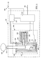
- a motor vehicle ignition locking system 100 comprises a control unit 110, an antenna unit 120 and an ignition switch 200, which ignition switch 200 can be operated by an electronic ignition key 300.
- the ignition locking system 100 is supplied with power from the vehicle battery 400.
- the ignition locking system 100 comprises an ignition switch 200, which comprises a housing 210.
- Said housing 210 accommodates a ignition switch cylinder 220, which is arranged to be turnable in the ignition switch turning direction 290 and arranged to receive an electronic ignition key 300.
- the ignition switch housing 210 also accommodates an electromagnet with a coil 260, a spring 250 and a retractable plunger 240.
- the plunger 240 is cylinder-shaped and spring-biased by the spring 250 to project into a recess 270 arranged in the cylinder 220.
- the recess 270 is shaped as an elongated groove dimensioned to receive the plunger 240, where the recess 270 extends in a radial direction alongside the wall of the cylinder 220. More precisely, the recess 270 begins where the plunger 240 projects into the cylinder 220, when the cylinder 220 is unturned. Then the recess 270 extends for about 31° in the opposite direction of the ignition turning direction 290, with addition for an angle ⁇ preferably corresponding to the half diameter of plunger 240. This enables a potential driver to insert an arbitrary but fitting key into the ignition switch 200 and turn the inserted key about 31° before the turning is stopped by the plunger 240 engaging the end of the recess 270, i.e.
- said turning may be stopped by the plunger 240 at some other angle, as the recess 270 in that embodiment may extend more or less than 31°, with addition for an angle ⁇ preferably corresponding to half the diameter of plunger 240.
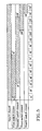
- the ignition switch 200 also comprises several electrical switches, arranged to distribute power to different functions in the vehicle. As show in fig. 4 said switches are implemented as sliding contacts, each contact having a sliding path 501-504 arranged on a first laminate 500 attached to the bottom of the turnable ignition cylinder 220. Each sliding path 501-504 has in turn an associated contact tip 601-604 arranged on a second laminate 600 attached to the bottom of the ignition switch housing 210. Said sliding paths 501-504 are actuated when the cylinder 220 is turned in the ignition turning direction 290.
- a first switch in this embodiment is arranged to distribute power to the coil 260 of the electromagnet when the cylinder 220 is turned within 14°-72°.
- a second switch in this embodiment is arranged to distribute power to the general vehicle electrical functions when the cylinder 220 is turned within 37°-130°.
- the general vehicle functions may e.g. be instrumentation light, compartment fan, vehicle floodlights etc.
- a third switch is arranged to distribute power to the vehicle ignition system when the ignition switch is turned 109°-150°.
- a fourth switch is arranged to distribute power to the vehicle cranking motor when the ignition switch is turned within 140°-150°, which cranking motor starts the vehicle engine.
- other type of switches may be used, which distributes power at other turning angles.
- the ignition switch housing 210 comprises an antenna coil 230 designed as a circle arranged on the top of the ignition switch housing 210 to closely surround an inserted electronic key 300. Electrical terminals (not shown) are arranged on each side of an opening in the circle formed by the antenna coil 230 to enable a connection of the antenna coil 230 to the antenna unit 120.
- the material and the constitution of the antenna coil 230 are adapted for enabling a wireless communication between an electronic ignition key and the vehicle circuitry.
- the ignition switch housing 210 also comprises a key-in switch 280, which is closed when a fitting key is inserted in the cylinder 220. Said key-in switch 280 supplies power to the control unit 110 and antenna unit 120 when it is closed. As shown in fig. 1 the key-in switch 280 may be positioned at the base of the ignition cylinder 220. However, it is preferred that the key-in switch 280 is positioned at the top or near the top of the cylinder 220. This has the advantage that the key-in switch 280 will be affected immediately when a key starts to enter the ignition cylinder 220, which enables a faster power up of the control unit 110 and the antenna unit 120.
- the invention is not limited to an ignition switch 200 as now described.
- the electromagnet and plunger 240 may be replaced by another electrically controllable device comprising a movable part.
- the recess 270 may e.g. be replaced by a protruding arrangement, as long as the same function is achieved.
- the trailing contacts with its tips 601-604 and associated sliding paths 501-504 may be replaced with another suitable switching arrangement without departing from the invention.
- the ignition locking system 100 comprises an antenna unit 120.
- the antenna unit 120 may be incorporated in the control unit 110 or another suitable unit without departing from the invention.
- the antenna unit 120 is supplied with power from the vehicle battery 400.
- the unit 120 is therefore connected to the positive pole of the vehicle battery 400 to receive a voltage. Said voltage may be adjusted by a voltage regulator or similar before it is used by the circuitry in the control unit 120.
- the antenna unit 120 is furthermore connected to the key-in switch 280, which in a closed position connects the unit 120 to the negative pole of the vehicle battery 400 and the unit 120 is hereby powered up.
- the antenna unit 120 is connected to the antenna coil 230 and the control unit 110.
- Said antenna unit 120 is preferably embodied as an electronic unit, which comprises a radio electronic circuitry for transmitting, receiving and processing a modulated frequency.
- the antenna unit 120 also comprises an interfacing circuitry for communicating with other vehicle units and a microprocessor with an associated memory for storing software, which at least is programmed to control the communication between the antenna unit 120, the antenna coil 230 and the electronic ignition key 300. Said communication enables the antenna unit 120 to extract the security code embodied in an electronic ignition key 300.
- a custom designed integrated circuit or some other circuitry may in an alternative embodiment replace the microprocessor and its associated memory, provided that the same functionality is accomplished.
- the antenna unit 120 is commanded by the control unit 110 to supply a modulated carrier frequency of preferably 125 kHz to the antenna coil 230, where the frequency is generated by the radio electronic circuitry arranged in the antenna unit 120. Said antenna coil 230 then radiates a corresponding electromagnetic wave within a short distance from the coil 230.
- the radiated electromagnetic wave is received by an electronic ignition key 300 inserted in the ignition switch 200, i.e. received by the transponder 310 arranged on the electronic ignition key 300.
- the transponder 310 then reflects a modified electromagnetic wave, accommodating information about the specific security code associated with the inserted key 300.
- the antenna coil 230 receives said modified wave and transmits it back to the antenna unit 120.
- the antenna unit 120 then amplifies, demodulates and signal processes the received modified wave to extract the security code associated with the inserted electronic ignition key.
- the communication between the antenna unit 120 and the electronic key 300 as now described may in an alternative embodiment be performed by optical means, e.g. infrared means.
- Infrared transceivers would then have to be arranged on the ignition switch 200 and the electronic ignition key 300 and the ignition key 300 would have to comprise electronic circuitry for storing and communicating the security code associated with the key 300.
- the electronic key 300 would also have to comprise a battery or some other energy source for supplying the electronic circuitry and the optical transceiver with power.
- the ignition locking system 100 comprises a control unit 110.
- the control unit 110 and the antenna unit 120 may be incorporated in another unit or constitute a part of another unit arranged in the vehicle, e.g. an unit comprising the general ignition system.
- the control unit 110 is preferably embodied as an electronic unit, which e.g. comprises interfacing circuitry for communicating with other vehicle units, a microprocessor and memory for storing of software, which at least is programmed to operate the ignition locking system 100.
- the control unit is preferably connected to the vehicle main bus system 401 for enabling communication with other vehicle systems, such as the main ignition system etc.
- the vehicle main bus system may be implemented by the use of any suitable bus system. However, is preferred to use a CAN-bus, which is a bus system well known in the area of automobile electronics.
- the control unit 110 is supplied with power from the vehicle battery 400.
- the unit 110 is therefore connected to the positive pole of the vehicle battery 400 to receive a voltage. Said voltage may be adjusted by a voltage regulator or similar before it is used by the circuitry in the control unit 110.
- the control unit 110 is furthermore connected to the key-in switch 280, which in a closed position connects the control unit 110 to the negative pole of the vehicle battery 400 and the control unit 110 is hereby powered up.
- control unit 110 is also connected to the antenna unit 120 for commanding said unit 120 to retrieve and subsequently deliver a security code associated with an electronic ignition key 300 that has been inserted in the ignition switch 200.
- the security code is verified when it has been retrieved and delivered to the control unit 110.
- the verification may e.g. be preformed through comparing the received key code with a code associated with the specific vehicle, which is pre-stored in the control unit 110.
- the inserted electronic ignition key 300 is then approved if the key code and the vehicle code are identical.
- the approval of an inserted electronic ignition key 300 permits the control unit 110 to enable an eventual powering up of the electromagnet coil 260 by connecting the first terminal of the coil 260 to the positive pole of the vehicle battery.
- a second terminal (not shown) of the electromagnet coil 260 is connected to the ignition switch 200.
- the ignition switch 200 will then subsequently connect the second terminal to the negative pole of the vehicle battery 400, when the electronic ignition key 300 and the ignition switch cylinder 220 has been turned preferably 14° in the ignition turning direction 290. This will energise the electromagnet coil 260, which electromagnet then retracts the plunger 240.
- Said ignition switch connection is preferably accomplished by the first electrical switch comprised by the ignition switch 200 according to this embodiment, which first electrical switch comprises a contact tip 601 and a sliding path 501 as shown in fig. 4.
- the electromagnet coil 260 may in an alternative embodiment have its second terminal connected directly to the negative pole of the vehicle battery, i.e. without any intermediary switch that has to be closed.
- a turning angle sensor (not shown) is then arranged on the ignition switch 200 to report the present turning angle of the ignition cylinder 220 to the control unit 110.
- the control unit 110 then connects said first terminal of the electromagnet coil 260 to the positive pole of the vehicle battery when the electronic ignition key 300 has been approved and the angle sensor reports that the cylinder 220 has been turned 14°. This will energise the coil 260 of the electromagnet, which electromagnet then retracts the plunger 240.
- the ignition locking system 100 is activated when the key-in switch 280 is closed by the insertion of a fitting key into the ignition switch cylinder 220.
- the control unit 110 and the antenna unit 120 are then powered up, whereupon the control unit 110 commands the antenna unit to retrieve the security code that is embodied in the transceiver 310, which is arranged on a proper electronic ignition key 300.
- the retrieved security code is communicated from the antenna unit 120 to the control unit 110, which then verifies the security code by comparing it with a security code associated with the specific motor vehicle.
- the ignition locking system 100 then remains locked if the inserted key is an ordinary key without a security code or if the key is a proper electronic ignition key 300, though with a security code that is not approved.
- the aspirant driver may then only turn the inserted key about 31° before the turning is stopped by the plunger 240 engaging the end of the recess 270, i.e. the recess stop 271.
- the ignition locking system 100 is unlocked if the key code and the vehicle code are identical or if the key code is otherwise approved.
- the unlocking of the ignition locking system is then accomplished in two steps.
- the first step is accomplished by the control unit 110, which connects the first terminal of the electromagnet coil 260 to the positive pole of the vehicle battery.
- the second step is accomplished by the ignition switch 200, which connects the second terminal of the electromagnet coil 260 to the negative pole of the vehicle battery when the electronic key 300 and the ignition cylinder 220 has been turned about 14°.
- the electromagnet is then activated and the plunger 240 is retracted from the recess 270, arranged in the ignition switch cylinder 220. This releases the ignition cylinder 220, which then can be turned further by the driver e.g.
- the operation of the ignition locking system and the ignition switch according to this invention provides that the electromagnet coil 260 is not supplied with power if a driver leaves the ignition key 300 inserted without turning it around, e.g. forgets to pull out the key when he leaves the vehicle or otherwise abandons the key in an inserted and unturned position.
- the recess 270 which extends radially alongside the wall of the cylinder 220 gives more time for the ignition locking system 100 to retract the plunger 240 from the recess 270 without obstructing the turning of the ignition switch cylinder 220.
Priority Applications (2)
| Application Number | Priority Date | Filing Date | Title |
|---|---|---|---|
| DE60321886T DE60321886D1 (de) | 2003-02-03 | 2003-02-03 | Elektrische Schlüsselsperre |
| EP20030002333 EP1442949B1 (de) | 2003-02-03 | 2003-02-03 | Elektrische Schlüsselsperre |
Applications Claiming Priority (1)
| Application Number | Priority Date | Filing Date | Title |
|---|---|---|---|
| EP20030002333 EP1442949B1 (de) | 2003-02-03 | 2003-02-03 | Elektrische Schlüsselsperre |
Publications (2)
| Publication Number | Publication Date |
|---|---|
| EP1442949A1 true EP1442949A1 (de) | 2004-08-04 |
| EP1442949B1 EP1442949B1 (de) | 2008-07-02 |
Family
ID=32605305
Family Applications (1)
| Application Number | Title | Priority Date | Filing Date |
|---|---|---|---|
| EP20030002333 Expired - Fee Related EP1442949B1 (de) | 2003-02-03 | 2003-02-03 | Elektrische Schlüsselsperre |
Country Status (2)
| Country | Link |
|---|---|
| EP (1) | EP1442949B1 (de) |
| DE (1) | DE60321886D1 (de) |
Citations (4)
| Publication number | Priority date | Publication date | Assignee | Title |
|---|---|---|---|---|
| EP0846820A1 (de) * | 1996-12-06 | 1998-06-10 | Siemens Aktiengesellschaft | Schliesssystem, insbesondere für ein Kraftfahrzeug |
| DE19821899A1 (de) * | 1998-05-15 | 1999-12-02 | Siemens Ag | Drehschalter, insbesondere Zündanlaßschalter |
| DE10057005A1 (de) * | 1999-11-18 | 2001-08-23 | Siemens Automotive Corp Lp | Elektronisches Verriegelungssystem |
| EP1148189A1 (de) * | 2000-04-22 | 2001-10-24 | Aug. Winkhaus GmbH & Co. KG | Elektromagnetisch aktivierbarer Sperrmechanismus |
-
2003
- 2003-02-03 EP EP20030002333 patent/EP1442949B1/de not_active Expired - Fee Related
- 2003-02-03 DE DE60321886T patent/DE60321886D1/de not_active Expired - Lifetime
Patent Citations (4)
| Publication number | Priority date | Publication date | Assignee | Title |
|---|---|---|---|---|
| EP0846820A1 (de) * | 1996-12-06 | 1998-06-10 | Siemens Aktiengesellschaft | Schliesssystem, insbesondere für ein Kraftfahrzeug |
| DE19821899A1 (de) * | 1998-05-15 | 1999-12-02 | Siemens Ag | Drehschalter, insbesondere Zündanlaßschalter |
| DE10057005A1 (de) * | 1999-11-18 | 2001-08-23 | Siemens Automotive Corp Lp | Elektronisches Verriegelungssystem |
| EP1148189A1 (de) * | 2000-04-22 | 2001-10-24 | Aug. Winkhaus GmbH & Co. KG | Elektromagnetisch aktivierbarer Sperrmechanismus |
Also Published As
| Publication number | Publication date |
|---|---|
| DE60321886D1 (de) | 2008-08-14 |
| EP1442949B1 (de) | 2008-07-02 |
Similar Documents
| Publication | Publication Date | Title |
|---|---|---|
| EP1659543B1 (de) | Sicherheitssystem und darin verwendete tragbare Vorrichtung | |
| EP1469428B2 (de) | Schalteinrichtung, insbesondere Zündschalter, mit Transponderabfrageeinrichtung über Radiowellen | |
| US4965460A (en) | Anti-theft system for a vehicle | |
| US6963794B2 (en) | Locking system for a motor vehicle | |
| US7290416B2 (en) | Engine switch device | |
| US6191703B1 (en) | Remote convience system and method with proximity-based disablement RFO preventing inadvertent function activation | |
| KR101076304B1 (ko) | 자동차용 전기 개방식 자물쇠 장치 | |
| US8542092B2 (en) | Keyless-go ignition switch with fault backup | |
| EP0767286A2 (de) | Fernbedienbares schlüsselloses Eingangs- und Wegfahrsperresystem für Kraftfahrzeuge | |
| EP2577617A1 (de) | Verbesserungen an oder im zusammenhang mit dem fahrzeugzugang | |
| US6188140B1 (en) | Immobilizer system-mounting vehicle and member used for the immobilizer system | |
| US6380642B1 (en) | Method for starting a motor vehicle and ignition-starter device | |
| US9725070B2 (en) | Electronic vehicle security system devoid of lock cylinders | |
| EP1442949B1 (de) | Elektrische Schlüsselsperre | |
| US5969596A (en) | Security system with automatic door locking/unlocking function | |
| JP2007277924A (ja) | キー装置 | |
| JP4001975B2 (ja) | 車両用エントリ制御システム | |
| KR20100079607A (ko) | 스마트키 시스템 | |
| EP2123521B1 (de) | Diebstahlsicherungssystem für Motorräder | |
| KR101314108B1 (ko) | 차량용 충전 포트 록 시스템 및 그 방법 | |
| JP2005329733A (ja) | 盗難防止装置 | |
| JP2005299264A (ja) | 無線タグ内臓のキー装置 | |
| JP2001115699A (ja) | 車両キーレスエントリー装置 | |
| JP3887739B2 (ja) | 車両用盗難防止装置 | |
| JP3332748B2 (ja) | キー装置 |
Legal Events
| Date | Code | Title | Description |
|---|---|---|---|
| PUAI | Public reference made under article 153(3) epc to a published international application that has entered the european phase |
Free format text: ORIGINAL CODE: 0009012 |
|
| AK | Designated contracting states |
Kind code of ref document: A1 Designated state(s): AT BE BG CH CY CZ DE DK EE ES FI FR GB GR HU IE IT LI LU MC NL PT SE SI SK TR |
|
| AX | Request for extension of the european patent |
Extension state: AL LT LV MK RO |
|
| 17P | Request for examination filed |
Effective date: 20041122 |
|
| 17Q | First examination report despatched |
Effective date: 20050304 |
|
| AKX | Designation fees paid |
Designated state(s): DE GB SE |
|
| RBV | Designated contracting states (corrected) |
Designated state(s): DE GB SE |
|
| RAP1 | Party data changed (applicant data changed or rights of an application transferred) |
Owner name: FORD GLOBAL TECHNOLOGIES, LLC. |
|
| 17Q | First examination report despatched |
Effective date: 20050304 |
|
| GRAP | Despatch of communication of intention to grant a patent |
Free format text: ORIGINAL CODE: EPIDOSNIGR1 |
|
| GRAS | Grant fee paid |
Free format text: ORIGINAL CODE: EPIDOSNIGR3 |
|
| GRAA | (expected) grant |
Free format text: ORIGINAL CODE: 0009210 |
|
| AK | Designated contracting states |
Kind code of ref document: B1 Designated state(s): DE GB SE |
|
| REG | Reference to a national code |
Ref country code: GB Ref legal event code: FG4D |
|
| GRAL | Information related to payment of fee for publishing/printing deleted |
Free format text: ORIGINAL CODE: EPIDOSDIGR3 |
|
| GRAS | Grant fee paid |
Free format text: ORIGINAL CODE: EPIDOSNIGR3 |
|
| REF | Corresponds to: |
Ref document number: 60321886 Country of ref document: DE Date of ref document: 20080814 Kind code of ref document: P |
|
| REG | Reference to a national code |
Ref country code: SE Ref legal event code: TRGR |
|
| PLBE | No opposition filed within time limit |
Free format text: ORIGINAL CODE: 0009261 |
|
| STAA | Information on the status of an ep patent application or granted ep patent |
Free format text: STATUS: NO OPPOSITION FILED WITHIN TIME LIMIT |
|
| 26N | No opposition filed |
Effective date: 20090403 |
|
| REG | Reference to a national code |
Ref country code: GB Ref legal event code: 732E Free format text: REGISTERED BETWEEN 20111020 AND 20111025 |
|
| REG | Reference to a national code |
Ref country code: DE Ref legal event code: R082 Ref document number: 60321886 Country of ref document: DE Representative=s name: LOUIS, POEHLAU, LOHRENTZ, DE |
|
| REG | Reference to a national code |
Ref country code: DE Ref legal event code: R082 Ref document number: 60321886 Country of ref document: DE Representative=s name: LOUIS, POEHLAU, LOHRENTZ, DE Effective date: 20120207 Ref country code: DE Ref legal event code: R081 Ref document number: 60321886 Country of ref document: DE Owner name: VOLVO CAR CORPORATION, SE Free format text: FORMER OWNER: FORD GLOBAL TECHNOLOGIES, LLC, DEARBORN, MICH., US Effective date: 20120207 |
|
| PGFP | Annual fee paid to national office [announced via postgrant information from national office to epo] |
Ref country code: SE Payment date: 20130226 Year of fee payment: 11 Ref country code: GB Payment date: 20130226 Year of fee payment: 11 Ref country code: DE Payment date: 20130221 Year of fee payment: 11 |
|
| REG | Reference to a national code |
Ref country code: DE Ref legal event code: R119 Ref document number: 60321886 Country of ref document: DE |
|
| REG | Reference to a national code |
Ref country code: SE Ref legal event code: EUG |
|
| GBPC | Gb: european patent ceased through non-payment of renewal fee |
Effective date: 20140203 |
|
| REG | Reference to a national code |
Ref country code: DE Ref legal event code: R119 Ref document number: 60321886 Country of ref document: DE Effective date: 20140902 |
|
| PG25 | Lapsed in a contracting state [announced via postgrant information from national office to epo] |
Ref country code: SE Free format text: LAPSE BECAUSE OF NON-PAYMENT OF DUE FEES Effective date: 20140204 |
|
| PG25 | Lapsed in a contracting state [announced via postgrant information from national office to epo] |
Ref country code: DE Free format text: LAPSE BECAUSE OF NON-PAYMENT OF DUE FEES Effective date: 20140902 Ref country code: GB Free format text: LAPSE BECAUSE OF NON-PAYMENT OF DUE FEES Effective date: 20140203 |