EP1442829A2 - Procédé de réparation des aubes statoriques d'une turbine à gaz par placage laser - Google Patents
Procédé de réparation des aubes statoriques d'une turbine à gaz par placage laser Download PDFInfo
- Publication number
- EP1442829A2 EP1442829A2 EP03256861A EP03256861A EP1442829A2 EP 1442829 A2 EP1442829 A2 EP 1442829A2 EP 03256861 A EP03256861 A EP 03256861A EP 03256861 A EP03256861 A EP 03256861A EP 1442829 A2 EP1442829 A2 EP 1442829A2
- Authority
- EP
- European Patent Office
- Prior art keywords
- base
- metal
- furnishing
- stationary shroud
- flow
- Prior art date
- Legal status (The legal status is an assumption and is not a legal conclusion. Google has not performed a legal analysis and makes no representation as to the accuracy of the status listed.)
- Ceased
Links
Images


Classifications
-
- B—PERFORMING OPERATIONS; TRANSPORTING
- B23—MACHINE TOOLS; METAL-WORKING NOT OTHERWISE PROVIDED FOR
- B23P—METAL-WORKING NOT OTHERWISE PROVIDED FOR; COMBINED OPERATIONS; UNIVERSAL MACHINE TOOLS
- B23P6/00—Restoring or reconditioning objects
- B23P6/002—Repairing turbine components, e.g. moving or stationary blades, rotors
- B23P6/007—Repairing turbine components, e.g. moving or stationary blades, rotors using only additive methods, e.g. build-up welding
-
- B—PERFORMING OPERATIONS; TRANSPORTING
- B23—MACHINE TOOLS; METAL-WORKING NOT OTHERWISE PROVIDED FOR
- B23K—SOLDERING OR UNSOLDERING; WELDING; CLADDING OR PLATING BY SOLDERING OR WELDING; CUTTING BY APPLYING HEAT LOCALLY, e.g. FLAME CUTTING; WORKING BY LASER BEAM
- B23K26/00—Working by laser beam, e.g. welding, cutting or boring
- B23K26/20—Bonding
- B23K26/32—Bonding taking account of the properties of the material involved
-
- B—PERFORMING OPERATIONS; TRANSPORTING
- B23—MACHINE TOOLS; METAL-WORKING NOT OTHERWISE PROVIDED FOR
- B23K—SOLDERING OR UNSOLDERING; WELDING; CLADDING OR PLATING BY SOLDERING OR WELDING; CUTTING BY APPLYING HEAT LOCALLY, e.g. FLAME CUTTING; WORKING BY LASER BEAM
- B23K26/00—Working by laser beam, e.g. welding, cutting or boring
- B23K26/34—Laser welding for purposes other than joining
-
- B—PERFORMING OPERATIONS; TRANSPORTING
- B23—MACHINE TOOLS; METAL-WORKING NOT OTHERWISE PROVIDED FOR
- B23K—SOLDERING OR UNSOLDERING; WELDING; CLADDING OR PLATING BY SOLDERING OR WELDING; CUTTING BY APPLYING HEAT LOCALLY, e.g. FLAME CUTTING; WORKING BY LASER BEAM
- B23K35/00—Rods, electrodes, materials, or media, for use in soldering, welding, or cutting
- B23K35/22—Rods, electrodes, materials, or media, for use in soldering, welding, or cutting characterised by the composition or nature of the material
- B23K35/24—Selection of soldering or welding materials proper
- B23K35/30—Selection of soldering or welding materials proper with the principal constituent melting at less than 1550 degrees C
- B23K35/3033—Ni as the principal constituent
-
- B—PERFORMING OPERATIONS; TRANSPORTING
- B23—MACHINE TOOLS; METAL-WORKING NOT OTHERWISE PROVIDED FOR
- B23K—SOLDERING OR UNSOLDERING; WELDING; CLADDING OR PLATING BY SOLDERING OR WELDING; CUTTING BY APPLYING HEAT LOCALLY, e.g. FLAME CUTTING; WORKING BY LASER BEAM
- B23K35/00—Rods, electrodes, materials, or media, for use in soldering, welding, or cutting
- B23K35/22—Rods, electrodes, materials, or media, for use in soldering, welding, or cutting characterised by the composition or nature of the material
- B23K35/24—Selection of soldering or welding materials proper
- B23K35/30—Selection of soldering or welding materials proper with the principal constituent melting at less than 1550 degrees C
- B23K35/3046—Co as the principal constituent
-
- C—CHEMISTRY; METALLURGY
- C23—COATING METALLIC MATERIAL; COATING MATERIAL WITH METALLIC MATERIAL; CHEMICAL SURFACE TREATMENT; DIFFUSION TREATMENT OF METALLIC MATERIAL; COATING BY VACUUM EVAPORATION, BY SPUTTERING, BY ION IMPLANTATION OR BY CHEMICAL VAPOUR DEPOSITION, IN GENERAL; INHIBITING CORROSION OF METALLIC MATERIAL OR INCRUSTATION IN GENERAL
- C23C—COATING METALLIC MATERIAL; COATING MATERIAL WITH METALLIC MATERIAL; SURFACE TREATMENT OF METALLIC MATERIAL BY DIFFUSION INTO THE SURFACE, BY CHEMICAL CONVERSION OR SUBSTITUTION; COATING BY VACUUM EVAPORATION, BY SPUTTERING, BY ION IMPLANTATION OR BY CHEMICAL VAPOUR DEPOSITION, IN GENERAL
- C23C24/00—Coating starting from inorganic powder
- C23C24/08—Coating starting from inorganic powder by application of heat or pressure and heat
- C23C24/10—Coating starting from inorganic powder by application of heat or pressure and heat with intermediate formation of a liquid phase in the layer
-
- C—CHEMISTRY; METALLURGY
- C23—COATING METALLIC MATERIAL; COATING MATERIAL WITH METALLIC MATERIAL; CHEMICAL SURFACE TREATMENT; DIFFUSION TREATMENT OF METALLIC MATERIAL; COATING BY VACUUM EVAPORATION, BY SPUTTERING, BY ION IMPLANTATION OR BY CHEMICAL VAPOUR DEPOSITION, IN GENERAL; INHIBITING CORROSION OF METALLIC MATERIAL OR INCRUSTATION IN GENERAL
- C23C—COATING METALLIC MATERIAL; COATING MATERIAL WITH METALLIC MATERIAL; SURFACE TREATMENT OF METALLIC MATERIAL BY DIFFUSION INTO THE SURFACE, BY CHEMICAL CONVERSION OR SUBSTITUTION; COATING BY VACUUM EVAPORATION, BY SPUTTERING, BY ION IMPLANTATION OR BY CHEMICAL VAPOUR DEPOSITION, IN GENERAL
- C23C26/00—Coating not provided for in groups C23C2/00 - C23C24/00
- C23C26/02—Coating not provided for in groups C23C2/00 - C23C24/00 applying molten material to the substrate
-
- F—MECHANICAL ENGINEERING; LIGHTING; HEATING; WEAPONS; BLASTING
- F01—MACHINES OR ENGINES IN GENERAL; ENGINE PLANTS IN GENERAL; STEAM ENGINES
- F01D—NON-POSITIVE DISPLACEMENT MACHINES OR ENGINES, e.g. STEAM TURBINES
- F01D9/00—Stators
- F01D9/02—Nozzles; Nozzle boxes; Stator blades; Guide conduits, e.g. individual nozzles
- F01D9/04—Nozzles; Nozzle boxes; Stator blades; Guide conduits, e.g. individual nozzles forming ring or sector
-
- B—PERFORMING OPERATIONS; TRANSPORTING
- B23—MACHINE TOOLS; METAL-WORKING NOT OTHERWISE PROVIDED FOR
- B23K—SOLDERING OR UNSOLDERING; WELDING; CLADDING OR PLATING BY SOLDERING OR WELDING; CUTTING BY APPLYING HEAT LOCALLY, e.g. FLAME CUTTING; WORKING BY LASER BEAM
- B23K2101/00—Articles made by soldering, welding or cutting
- B23K2101/001—Turbines
-
- B—PERFORMING OPERATIONS; TRANSPORTING
- B23—MACHINE TOOLS; METAL-WORKING NOT OTHERWISE PROVIDED FOR
- B23K—SOLDERING OR UNSOLDERING; WELDING; CLADDING OR PLATING BY SOLDERING OR WELDING; CUTTING BY APPLYING HEAT LOCALLY, e.g. FLAME CUTTING; WORKING BY LASER BEAM
- B23K2103/00—Materials to be soldered, welded or cut
- B23K2103/18—Dissimilar materials
- B23K2103/26—Alloys of Nickel and Cobalt and Chromium
-
- B—PERFORMING OPERATIONS; TRANSPORTING
- B23—MACHINE TOOLS; METAL-WORKING NOT OTHERWISE PROVIDED FOR
- B23K—SOLDERING OR UNSOLDERING; WELDING; CLADDING OR PLATING BY SOLDERING OR WELDING; CUTTING BY APPLYING HEAT LOCALLY, e.g. FLAME CUTTING; WORKING BY LASER BEAM
- B23K2103/00—Materials to be soldered, welded or cut
- B23K2103/50—Inorganic material, e.g. metals, not provided for in B23K2103/02 – B23K2103/26
-
- F—MECHANICAL ENGINEERING; LIGHTING; HEATING; WEAPONS; BLASTING
- F05—INDEXING SCHEMES RELATING TO ENGINES OR PUMPS IN VARIOUS SUBCLASSES OF CLASSES F01-F04
- F05D—INDEXING SCHEME FOR ASPECTS RELATING TO NON-POSITIVE-DISPLACEMENT MACHINES OR ENGINES, GAS-TURBINES OR JET-PROPULSION PLANTS
- F05D2230/00—Manufacture
- F05D2230/80—Repairing, retrofitting or upgrading methods
Definitions
- This invention relates to aircraft gas turbine engines and, more particularly, to the repair of a stationary shroud that has previously been in service.
- gas turbine In an aircraft gas turbine (jet) engine, air is drawn into the front of the engine, compressed by a shaft-mounted compressor, and mixed with fuel. The mixture is burned, and the hot combustion gases are passed through a gas turbine mounted on the same shaft. The flow of combustion gas turns the gas turbine by impingement against an airfoil section of the turbine blades and vanes, which turns the shaft and provides power to the compressor. The hot exhaust gases flow from the back of the engine, driving it and the aircraft forward.
- jet gas turbine
- annular, circumferentially extending stationary shroud surrounds the tips of the rotor blades.
- the stationary shroud confines the combustion gases to the gas flow path so that the combustion gas is utilized with maximum efficiency to turn the gas turbine.
- the clearance between the turbine blade tips and the stationary shroud is minimized to prevent the leakage of combustion gases around the tips of the turbine blades.
- the stationary shroud provides a rubbing surface for the tips of the turbine blades.
- the design intent is for the turbine blade tips to rub into the stationary shroud, with the contact acting in the manner of a seal.
- the clearance between the blade tips and the stationary shroud, and thence the amount of combustion gas that can bypass the turbine blades, is minimized, thereby ensuring maximum efficiency of the engine.
- the stationary shroud must be manufactured to and maintained at highly exacting tolerances in order to achieve this efficiency during extended service.
- the gas path surface of the stationary shroud is exposed to abrasion by the rotating turbine blade tips and also to erosion, oxidation, and corrosion by the hot combustion gases.
- the base metal of the stationary shroud is typically not highly resistant to the environmental attack and abrasion, and therefore an environmentally resistant rub coating is applied on the gas path surface of the stationary shroud. Over a period of time as the engine operates, the surface of the environmentally resistant rub coating is worn away, and some of the base metal of the stationary shroud may also be damaged and/or removed. The result is that the dimensions of the stationary shroud are reduced below the required tolerances for efficient operation of the gas turbine engine.
- the annular radius of the inwardly facing surface of the stationary shroud gradually increases, so that an increasing amount of combustion gas leaks around the tips of the turbine blades and the operating efficiency is reduced. At some point, the stationary shroud is no longer operating acceptably and the operation of the gas turbine degrades below acceptable levels.
- the present invention provides a technique for restoring the mechanical properties as well as the dimensions, environmental resistance, and rub resistance of the flow-path surface of a stationary shroud of a gas turbine engine, and a stationary shroud repaired by this approach.
- the present method is typically utilized after the gas turbine engine has been in service and the stationary shroud has been subjected to extended operation in combustion gas, high temperatures, and rubbing from the movement of the turbine blades.
- the present approach may be utilized with conventional procedures known for use in other applications.
- a method for repairing a stationary shroud of a gas turbine engine comprises the steps of furnishing the stationary shroud that has previously been in service, wherein the stationary shroud is made of a base metal, removing any damaged material from a flow-path region of the stationary shroud to leave an initially exposed base-metal flow-path surface, and applying a base-metal restoration overlying the initially exposed flow-path surface.
- the step of applying includes the steps of furnishing a source of a structural material that is compatible with the base metal, and depositing the source of the structural material overlying the initially exposed base-metal flow-path surface of the stationary shroud by laser cladding to form a repaired base-metal flow-path surface.
- the base-metal restoration is typically in-process machined to its desired dimensions, shape, and surface finish.
- the source of the structural material may have substantially the same composition as the base metal, or a different composition.
- the source of the structural material may be a powder.
- the powder may be pre-positioned overlying the initially exposed flow-path surface, and thereafter fused using a laser.
- a laser beam may be directed toward the initially exposed flow-path surface, and simultaneously the powder may be injected into the laser beam so that the powder is fused and deposited.
- the source of the structural material may instead be a wire that is fed into the laser beam and fused onto the surface that is being restored.
- the stationary shroud may be any stationary shroud, but it is preferably a high pressure turbine stationary shroud.
- the stationary shroud may be made of any operable material, but it is preferably made of a nickel-base alloy or a cobalt-base alloy.
- an environmentally resistant rub coating is thereafter applied overlying the base-metal restoration.
- the environmentally resistant rub coating defines a rub-coating surface, and the rub-coating surface is typically shaped, as by machining, to the required shape and dimensions. While this rub-coating material may be any corrosion resistant, oxidation resistant and rub tolerant powder, MCrAIY compositions have been found to be most suitable.
- the present invention is an advancement of the technology for repairing and restoring shrouds for engine service. Unlike stationary shrouds repaired by the TDC process, stationary shrouds repaired in accordance with the present invention are not temperature-limited because of additions of melting point depressants such as boron or silicon.
- the present invention is also an advance over low pressure plasma spraying (LPPS) since no partial vacuum is required during the deposition of the restoration, making the present process faster, cheaper, more effective and easier to perform.
- LPPS low pressure plasma spraying
- Other advantages include less process variation and no preheat. Very importantly, there is much less part distortion, so that the ability to restore the shroud to the original drawing tolerances can be done more easily and with less machining.
- the present approach provides achieves results superior to ADH, because the stationary shroud is restored to its original dimensions using a structural material, rather than the rub-resistant coating.
- the rub-resistant coating is preferably applied over the dimensionally restored base metal of the stationary shroud.
- FIG. 1 is a cross-sectional view generally depicting a stationary shroud assembly 20 in relation to a turbine blade 22.
- the stationary shroud assembly 20 includes a stationary shroud 24 having a flow-path surface 26 in a facing relation to a turbine blade tip 28 of the turbine blade 22.
- the stationary shroud 24 refers to structure which does not rotate as the turbine blade 22 turns with its supporting turbine disk (not shown) and turbine shaft (not shown).
- the stationary shroud 24 is to be distinguished from the rotating shroud that is found at the tip of some other types of blades and is a part of the blade, and which does rotate as the blade turns.
- a small gap 30 separates the flow-path surface 26 from the turbine blade tip 28.
- a stationary shroud support 32 from which the stationary shroud 22 is supported a stationary shroud hanger support 34 from which the stationary shroud support 32 is supported, and a support case 36 from which the stationary shroud hanger support 34 is supported.
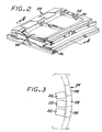
- the stationary shroud 24 is typically formed of a circumferentially extending series of individual stationary shroud segments 38.
- Figure 2 illustrates one of the stationary shroud segments 38
- Figure 3 depicts the manner in which the individual stationary shroud segments 38 are assembled together in a circumferentially abutting fashion to form the annular, generally cylindrical stationary shroud 24.
- the structure of the stationary shrouds is described more fully in US Patent 6,233,822, whose disclosure is incorporated by reference.
- the turbine blades 22 When the gas turbine engine is operated, the turbine blades 22 rotate. As they rotate and are heated to elevated temperature, the turbine blades 22 elongate so that the gap 30 is reduced to zero and the turbine blade tips 28 contact and cut into the flow-path surface 26 and wear away the material of the stationary shroud 24 at the flow-path surface 26. Over time, the gap 30 becomes larger as material is abraded from both the turbine blade tips 28 and the stationary shroud 24, and also lost from the turbine blade tips 28 and the stationary shroud 24 by erosion, oxidation, and corrosion in the hot combustion gases. As the gap 30 becomes larger, the efficiency of the gas turbine decreases. At some point, the gas turbine engine is removed from service and repaired.
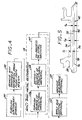
- Figure 4 depicts a preferred approach for repairing the stationary shroud 24.
- the stationary shroud 24 that has previously been in service is furnished, step 50.
- the stationary shroud 24 is a high pressure turbine stationary shroud.
- the stationary shroud is made of a base metal 42, see Figure 5.
- the base metal 42 of the stationary shroud 24 is preferably either a nickel-base alloy or a cobalt-base alloy.
- Examples of such base-metal alloys include L605, having a nominal composition by weight of about 20 percent chromium, about 10 percent nickel, about 15 percent tungsten, about 3 percent iron, about 1 percent silicon, about 1.5 percent manganese, about 0.1 percent carbon, and the balance cobalt and incidental impurities; ReneTM N5, having a nominal composition by weight of 7.5 percent cobalt, 7 percent chromium, 6.2 percent aluminum, 6.5 percent tantalum, 5 percent tungsten, 3 percent rhenium, 1.5 percent molybdenum, 0.15 percent hafnium, 0.05 percent carbon, 0.004 percent boron and the balance nickel and incidental impurities; IN-738 having a nominal composition by weight of 8.5 percent cobalt, 16 percent chromium, 3.4 percent aluminum, 3.8 percent titanium, 1.75 percent tantalum, 2.6 percent tungsten, 1.75 percent tantalum, 0.012 percent boron 0.0.12 percent zirconium, 0.05 percent niobium and the balance nickel and
- any damaged material is removed from a flow-path region 40 of the stationary shroud 24, step 52, to leave an initially exposed base-metal flow-path surface 70, see Figure 5.
- the flow-path region 40 generally corresponds with the location of the flow-path surface 26 of Figure 1, but is not exactly coincident because of the presence of damaged material and the loss of base metal 42 during service.
- the damaged material may include remnants of the prior rub coating, damaged base metal, and oxidation, corrosion, and erosion products, as well as soot.
- the damaged material may be removed by any operable approach.
- the flow-path region 40 is first degreased by any operable approach.
- the flow-path region 40 is then ground or grit-blasted to remove any tightly adhering oxides.
- the flow-path region 40 is acid stripped to remove any aluminides, followed by a fluoride-ion cleaning (FIC).
- FIC fluoride-ion cleaning
- a base-metal restoration 72 is applied overlying and in contact with the initially exposed flow-path surface 70 in the flow-path region 40, step 54.
- the base-metal restoration 72 has a thickness t A that, when added to t 0 , increases the thickness of the backside-pocket portion 74 of the flow-path region 40 to a restored thickness t R , which is within the tolerance range of the thickness specification for the backside-pocket 74.
- the step of applying 54 includes the steps of furnishing a source of a structural material that is compatible with the base metal 42, step 56, and depositing the structural material overlying the initially exposed base-metal flow-path surface 70 of the stationary shroud 24 by laser cladding to form a repaired flow-path surface 76, step 58.
- Laser cladding is a known process for other applications.
- the structural material used in the restoration step 54 to apply the base-metal restoration 72 may have substantially the same composition as the base metal 42.
- the use of substantially the same composition for the restoration as the base-metal composition is preferred, so that the base metal 42 of the stationary shroud 24 and the base-metal restoration 72 are fully compatible both chemically, in respect to properties'such as the formation of new phases through interdiffusion, and physically, in respect to properties such as the bonding of the base metal 42 and the base-metal restoration 72, avoiding mismatch of the coefficients of thermal expansion, and melting points.
- the structural material used in the restoration step 54 to apply the base-metal restoration 72 may instead have a different composition than the base metal 42 to achieve particular properties that may not be achievable when the base-metal restoration 72 is the same composition as the base metal 42.
- a powder of the structural material is pre-positioned overlying the initially exposed flow-path surface 70. That is, the powder is pre-positioned by placing it onto the initially exposed flow-path surface 70 prior to any heating of the powder.
- the powder may be lightly sintered or held togther with a binder such as an acrylic binder, so that it remains in the desired location before being fused by laser.
- the powder is fused (melted) using a laser 80 whose power output is adjusted such that the powder is melted and that the very top-most portion of the initially exposed flow-path surface 70 is locally melted, but such that the underlying structure of the stationary shroud 24 is not melted or even heated to a substantial fraction of its melting point.
- the underlying structure of the stationary shroud 24 instead acts as a heat sink.
- the laser 80 is moved laterally relative to the initially exposed flow-path surface 70 so that the pre-positioned powder is progressively melted when exposed to the laser beam 82, and then progressively allowed to solidify as the laser 80 moves onwardly and no longer heats a particular area.
- the laser beam 82 is directed from the laser 80 toward the initially exposed flow-path surface 70.
- a powder flow 84 of the restoration powder is injected from a powder injector 86 into the laser beam 82 and upon the initially exposed flow-path surface 70 so that the powder is fused and deposited onto the initially exposed flow-path surface 70.
- the power level of the laser 80 is selected so that the injected powder is melted and the topmost portion of the base metal 42 is melted, but that the underlying portion of the base metal 42 is not melted.
- the laser 80 and the powder injector 86 move together laterally across the initially exposed flow-path surface 70, so that the injected powder is progressively melted when exposed to the laser beam 82, and then progressively allowed to solidify as the laser 80 moves onwardly and no longer heats a particular area.
- the laser beam 82 is directed from the laser 80 toward the initially exposed flow-path surface 70.
- a wire 88 of the structural material is fed into the heated zone with a wire feed, schematically indicated by a wire feed arrow 90, so that the metal of the wire 88 is fused and deposited onto the initially exposed flow-path surface 70.
- the wire 88 may be supplied in discrete lengths or as a continuous coil.
- the power level of the laser 80 is selected so that the wire 88 is melted and the topmost portion of the base metal 42 is melted, but that the underlying portion of the base metal 42 is not melted.
- the laser 80 and the wire feed 90 move together laterally across the initially exposed flow-path surface 70, so that the injected powder is progressively melted when exposed to the laser beam 82, and then progressively allowed to solidify as the laser 80 moves onwardly and no longer heats a particular area.
- the feed may involve two or more of some of the powder being pre-positioned as in Figure 6, some of the powder injected, as in Figure 7, and a wire feed of material as in Figure 8.
- the present approach offers distinct advantages over other techniques.
- the flow-path region 40 which the base-metal restoration 72 is applied is typically rather thin. To avoid distorting the thin base metal 42, it is desirable that the heat input during the restoration 54 be no greater than necessary.
- the laser 80 has a well-defined, precise beam that melts the restoration material but does not introduce more heat than necessary.
- the use of the prepositioned powder in the embodiment of Figure 6 protects the initially exposed flow-path surface 70 from direct impingement of the laser beam 82 so that minimal heat flows into the base metal 42 through that surface 70.
- the restoration material and the uppermost portion of the initially exposed flow-path surface 70 are melted during the heating, there is a strong metallurgical bond between the restoration 72 and the underlying base metal 42, unlike some other techniques such as some thermal spray processes.
- the present approach also produces a relatively large grain size in the restoration 72, when compared to LPPS and HVOF processes, which is desirable for creep and rupture properties.
- the result is the solidified base-metal restoration 72, with its repaired flow-path surface 76, deposited overlying and upon the initially exposed flow-path surface 70.
- the deposited base-metal restoration is then in-process machined, numeral 60, so that the total restored thickness t R of the base metal is the desired value and the shape of the repaired base-metal flow-path surface 76 is correct.
- the powder deposition process 58 is not sufficiently precise to achieve exactly the correct thickness and shape, and the in-process machining step 60 is used.
- an environmentally resistant rub coating 78 is applied overlying and contacting the base-metal restoration 72, step 62.
- the rub coating 78 is preferably a material, typically in the form of a powder and having enhanced environmental resistance which is rub compliant.
- rub coating materials include an MCrAIY(X) where M is an element selected from the group consisting of cobalt and nickel and combinations thereof and (X) is an element selected from the group of solid solution strengtheners and gamma prime formers consisting of titanium, tantalum, rhenium, molybdenum, and tungsten, and grain boundary strengtheners consisting of boron, carbon, hafnium, and zirconium, and combinations thereof; and BC-52 alloy, having a nominal composition, in weight percent, of about 18 percent chromium, about 6.5 percent aluminum, about 10 percent cobalt, about 6 percent tantalum, about 2 percent rhenium, about 0.5 percent hafnium, about 0.3 percent yttrium, about 1 percent silicon, about 0.015 percent zirconium, about 0.015 percent boron, about 0.06 percent carbon, the balance nickel and incidental impurities.
- M is an element selected from the group consisting of cobalt and nickel and combinations thereof
- X is an element selected from the
- the rub coating is applied by any operable approach, but preferably by the HVOF (high-velocity oxyfuel) process.
- the rub coating 78 is preferably in the range of about 0.005-0.150 inches in thickness, most preferably in the range of from 0.005-0.050 inches in thickness.
- the HVOF process which utilizes a high velocity gas as a protective shield to prevent oxide formation, is a relatively low temperature thermal spray that allow for application of a high density oxide-free coating in a wide variety of thicknesses, is known in the art.
- the HVOF process typically uses any one of a variety of fuel gases, such as oxygen, oxypropylene, oxygen/hydrogen mixtures or kerosene. Gas flow of the fuel can be varied from 2000-5000 ft/sec.
- the temperature of the spray will depend on the combustion temperature of the fuel gas used, but will typically be in the range of 3000-5000.degree. F.
- a slight excess thickness of the rub coating 78 is applied, and then the excess is removed to shape the flow-path surface 26 and achieve the desired dimensional thickness of the rub coating 78.
- any features that have been obscured by the steps 52, 54, and 60, such as holes or corners, are restored.
- the rub coating 78 As in the case of the base-metal restoration 72, it is difficult to deposit the rub coating 78 to precisely the desired thickness, shape, and surface finish.
- the surface of the rub coating is optionally machined, step 64, to the desired shape and thickness, as well as to the desired surface finish.
Landscapes
- Engineering & Computer Science (AREA)
- Mechanical Engineering (AREA)
- Chemical & Material Sciences (AREA)
- Optics & Photonics (AREA)
- Physics & Mathematics (AREA)
- Organic Chemistry (AREA)
- Metallurgy (AREA)
- Materials Engineering (AREA)
- Chemical Kinetics & Catalysis (AREA)
- Plasma & Fusion (AREA)
- General Engineering & Computer Science (AREA)
- Laser Beam Processing (AREA)
- Other Surface Treatments For Metallic Materials (AREA)
- Turbine Rotor Nozzle Sealing (AREA)
Applications Claiming Priority (2)
| Application Number | Priority Date | Filing Date | Title |
|---|---|---|---|
| US10/286,122 US20040086635A1 (en) | 2002-10-30 | 2002-10-30 | Method of repairing a stationary shroud of a gas turbine engine using laser cladding |
| US286122 | 2002-10-30 |
Publications (2)
| Publication Number | Publication Date |
|---|---|
| EP1442829A2 true EP1442829A2 (fr) | 2004-08-04 |
| EP1442829A3 EP1442829A3 (fr) | 2006-01-25 |
Family
ID=32175356
Family Applications (1)
| Application Number | Title | Priority Date | Filing Date |
|---|---|---|---|
| EP03256861A Ceased EP1442829A3 (fr) | 2002-10-30 | 2003-10-30 | Procédé de réparation des aubes statoriques d'une turbine à gaz par placage laser |
Country Status (6)
| Country | Link |
|---|---|
| US (2) | US20040086635A1 (fr) |
| EP (1) | EP1442829A3 (fr) |
| JP (1) | JP4301402B2 (fr) |
| BR (1) | BR0304067A (fr) |
| CA (1) | CA2446343A1 (fr) |
| SG (1) | SG120130A1 (fr) |
Cited By (4)
| Publication number | Priority date | Publication date | Assignee | Title |
|---|---|---|---|---|
| GB2409507A (en) * | 2003-12-22 | 2005-06-29 | Caterpillar Inc | Method of repairing a part, particularly a piston, using laser cladding |
| EP1563945A3 (fr) * | 2004-02-13 | 2005-12-07 | United Technologies Corporation | Réparation d'un élément par placage laser |
| CN102615431A (zh) * | 2012-04-12 | 2012-08-01 | 中国人民解放军装甲兵工程学院 | 一种灰铸铁缸盖自动化激光熔覆再制造方法 |
| CN106521487A (zh) * | 2016-11-10 | 2017-03-22 | 中国人民解放军装甲兵工程学院 | 一种服役中期钛合金压气机叶片的再制造方法 |
Families Citing this family (53)
| Publication number | Priority date | Publication date | Assignee | Title |
|---|---|---|---|---|
| US7009137B2 (en) * | 2003-03-27 | 2006-03-07 | Honeywell International, Inc. | Laser powder fusion repair of Z-notches with nickel based superalloy powder |
| US6887529B2 (en) * | 2003-04-02 | 2005-05-03 | General Electric Company | Method of applying environmental and bond coatings to turbine flowpath parts |
| US7360991B2 (en) * | 2004-06-09 | 2008-04-22 | General Electric Company | Methods and apparatus for fabricating gas turbine engines |
| DE102004042878A1 (de) * | 2004-09-04 | 2006-03-09 | Mtu Aero Engines Gmbh | Verfahren zur Reparatur von Turbomaschinenschaufeln |
| US7378132B2 (en) * | 2004-12-14 | 2008-05-27 | Honeywell International, Inc. | Method for applying environmental-resistant MCrAlY coatings on gas turbine components |
| US20070079507A1 (en) * | 2005-10-12 | 2007-04-12 | Kenny Cheng | Blade shroud repair |
| EP1785583A3 (fr) * | 2005-10-12 | 2010-06-23 | Turbine Overhaul Services Private Limited | Réparation d'une virole pour aube de turbine |
| CN100462189C (zh) * | 2005-12-26 | 2009-02-18 | 沈阳大陆激光技术有限公司 | 一种燃气轮机护环的维修工艺 |
| SG134183A1 (en) * | 2006-01-16 | 2007-08-29 | United Technologies Corp | Turbine component trailing edge and platform restoration by laser cladding |
| US7653994B2 (en) * | 2006-03-22 | 2010-02-02 | General Electric Company | Repair of HPT shrouds with sintered preforms |
| US7851984B2 (en) * | 2006-08-08 | 2010-12-14 | Federal-Mogul World Wide, Inc. | Ignition device having a reflowed firing tip and method of construction |
| US20080148708A1 (en) * | 2006-12-20 | 2008-06-26 | General Electric Company | Turbine engine system with shafts for improved weight and vibration characteristic |
| US20090053045A1 (en) * | 2007-08-22 | 2009-02-26 | General Electric Company | Turbine Shroud for Gas Turbine Assemblies and Processes for Forming the Shroud |
| EP2075416B1 (fr) * | 2007-12-27 | 2011-05-18 | Techspace Aero | Procédé de fabrication d'un élément de turbomachine et dispositif ainsi obtenu |
| US8061142B2 (en) * | 2008-04-11 | 2011-11-22 | General Electric Company | Mixer for a combustor |
| US20090271983A1 (en) * | 2008-04-30 | 2009-11-05 | Rose William M | Method to weld repair blade outer air seals |
| EP2226149A1 (fr) * | 2009-03-04 | 2010-09-08 | Siemens Aktiengesellschaft | Procédé de soudure en deux étapes |
| US8373089B2 (en) * | 2009-08-31 | 2013-02-12 | General Electric Company | Combustion cap effusion plate laser weld repair |
| US9133542B2 (en) | 2009-11-30 | 2015-09-15 | United Technologies Corporation | Coating methods and apparatus |
| EP2330349B1 (fr) * | 2009-12-01 | 2018-10-24 | Siemens Aktiengesellschaft | Brûleur pilote pour chambre de combustion de turbine à gaz, chambre de combustion, et moteur de turbine à gaz |
| DE102010010595A1 (de) * | 2010-03-08 | 2011-09-08 | Lufthansa Technik Ag | Verfahren zur Reparatur von Dichtsegmenten in der Rotor-/Statordichtung einer Gasturbine |
| US8613590B2 (en) * | 2010-07-27 | 2013-12-24 | United Technologies Corporation | Blade outer air seal and repair method |
| US8708659B2 (en) | 2010-09-24 | 2014-04-29 | United Technologies Corporation | Turbine engine component having protective coating |
| US8870523B2 (en) | 2011-03-07 | 2014-10-28 | General Electric Company | Method for manufacturing a hot gas path component and hot gas path turbine component |
| FR2977177B1 (fr) | 2011-06-30 | 2014-04-04 | Chpolansky Ets | Procede de rechargement d'une piece |
| US9127549B2 (en) | 2012-04-26 | 2015-09-08 | General Electric Company | Turbine shroud cooling assembly for a gas turbine system |
| US9828872B2 (en) | 2013-02-07 | 2017-11-28 | General Electric Company | Cooling structure for turbomachine |
| US9015944B2 (en) | 2013-02-22 | 2015-04-28 | General Electric Company | Method of forming a microchannel cooled component |
| US9394796B2 (en) | 2013-07-12 | 2016-07-19 | General Electric Company | Turbine component and methods of assembling the same |
| KR102126866B1 (ko) * | 2013-08-07 | 2020-06-25 | 한화파워시스템 주식회사 | 유체 회전 기계의 임펠러 조립체 및 임펠러 조립체의 제조 방법 |
| US9416662B2 (en) | 2013-09-03 | 2016-08-16 | General Electric Company | Method and system for providing cooling for turbine components |
| BR112016011777A2 (pt) | 2013-11-27 | 2017-08-08 | Gen Electric | Aparelhos de bocal de combustível |
| CN103659201B (zh) * | 2013-12-15 | 2015-12-30 | 无锡透平叶片有限公司 | 一种采用激光熔覆防水蚀的汽轮机叶片的加工工艺 |
| JP6695801B2 (ja) | 2013-12-23 | 2020-05-20 | ゼネラル・エレクトリック・カンパニイ | 可撓性支持構造体を備えた燃料ノズル |
| US10451282B2 (en) | 2013-12-23 | 2019-10-22 | General Electric Company | Fuel nozzle structure for air assist injection |
| CN104164665A (zh) * | 2014-07-24 | 2014-11-26 | 新疆汇翔激光科技有限公司 | 一种利用光纤激光对挖盐机缸套的修复方法 |
| EP3061556B1 (fr) | 2015-02-26 | 2018-08-15 | Rolls-Royce Corporation | Procédé de réparation de composants métalliques à paroi double au moyen d'un matériau de brasage et composant ainsi obtenu |
| EP3061557B1 (fr) * | 2015-02-26 | 2018-04-18 | Rolls-Royce Corporation | Réparation de composants métalliques à paroi double au moyen d'un apport de matériau de dépôt à énergie dirigée |
| US10247027B2 (en) | 2016-03-23 | 2019-04-02 | United Technologies Corporation | Outer airseal insulated rub strip |
| US10669878B2 (en) | 2016-03-23 | 2020-06-02 | Raytheon Technologies Corporation | Outer airseal abradable rub strip |
| US10267174B2 (en) | 2016-04-28 | 2019-04-23 | United Technologies Corporation | Outer airseal abradable rub strip |
| US10544683B2 (en) | 2016-08-30 | 2020-01-28 | Rolls-Royce Corporation | Air-film cooled component for a gas turbine engine |
| US20180073390A1 (en) | 2016-09-13 | 2018-03-15 | Rolls-Royce Corporation | Additively deposited gas turbine engine cooling component |
| US10689984B2 (en) | 2016-09-13 | 2020-06-23 | Rolls-Royce Corporation | Cast gas turbine engine cooling components |
| US10858950B2 (en) | 2017-07-27 | 2020-12-08 | Rolls-Royce North America Technologies, Inc. | Multilayer abradable coatings for high-performance systems |
| US10900371B2 (en) | 2017-07-27 | 2021-01-26 | Rolls-Royce North American Technologies, Inc. | Abradable coatings for high-performance systems |
| CN107502889A (zh) * | 2017-08-16 | 2017-12-22 | 重庆市科学技术研究院 | 一种精确激光熔覆镍基合金粉末的方法 |
| US10808565B2 (en) * | 2018-05-22 | 2020-10-20 | Rolls-Royce Plc | Tapered abradable coatings |
| US11090771B2 (en) | 2018-11-05 | 2021-08-17 | Rolls-Royce Corporation | Dual-walled components for a gas turbine engine |
| US11305363B2 (en) | 2019-02-11 | 2022-04-19 | Rolls-Royce Corporation | Repair of through-hole damage using braze sintered preform |
| CN112695318A (zh) * | 2020-12-22 | 2021-04-23 | 天津修船技术研究所(中国船舶重工集团公司第六三一三研究所) | 一种碟片式分离机中转鼓的喷嘴流道的维修方法 |
| CN116604271A (zh) * | 2021-03-31 | 2023-08-18 | 中国航发常州兰翔机械有限责任公司 | 一种航空发动机轴流机匣流道修复用工装的使用方法 |
| US11692446B2 (en) | 2021-09-23 | 2023-07-04 | Rolls-Royce North American Technologies, Inc. | Airfoil with sintered powder components |
Citations (2)
| Publication number | Priority date | Publication date | Assignee | Title |
|---|---|---|---|---|
| EP1013788A1 (fr) * | 1998-12-22 | 2000-06-28 | General Electric Company | Réparation des anneaux de cerclage à haute pression de turbine |
| US6364971B1 (en) * | 2000-01-20 | 2002-04-02 | Electric Power Research Institute | Apparatus and method of repairing turbine blades |
Family Cites Families (13)
| Publication number | Priority date | Publication date | Assignee | Title |
|---|---|---|---|---|
| US4743733A (en) * | 1984-10-01 | 1988-05-10 | General Electric Company | Method and apparatus for repairing metal in an article |
| US5484665A (en) * | 1991-04-15 | 1996-01-16 | General Electric Company | Rotary seal member and method for making |
| FR2688803B1 (fr) * | 1992-03-23 | 1994-05-06 | European Gas Turbines Sa | Procede de revetement d'une encoche d'une piece en alliage de nickel par laser. |
| US5889254A (en) * | 1995-11-22 | 1999-03-30 | General Electric Company | Method and apparatus for Nd: YAG hardsurfacing |
| US5759641A (en) * | 1996-05-15 | 1998-06-02 | Dimitrienko; Ludmila Nikolaevna | Method of applying strengthening coatings to metallic or metal-containing surfaces |
| US6269540B1 (en) * | 1998-10-05 | 2001-08-07 | National Research Council Of Canada | Process for manufacturing or repairing turbine engine or compressor components |
| US6154959A (en) * | 1999-08-16 | 2000-12-05 | Chromalloy Gas Turbine Corporation | Laser cladding a turbine engine vane platform |
| CN1175954C (zh) * | 2000-05-10 | 2004-11-17 | 中国科学院金属研究所 | 燃气轮机带冠叶片冠部阻尼面激光敷层工艺方法 |
| US6933061B2 (en) * | 2002-12-12 | 2005-08-23 | General Electric Company | Thermal barrier coating protected by thermally glazed layer and method for preparing same |
| US7494619B2 (en) * | 2003-12-23 | 2009-02-24 | General Electric Company | High temperature alloys, and articles made and repaired therewith |
| US6905728B1 (en) * | 2004-03-22 | 2005-06-14 | Honeywell International, Inc. | Cold gas-dynamic spray repair on gas turbine engine components |
| US20080182017A1 (en) * | 2007-01-31 | 2008-07-31 | General Electric Company | Laser net shape manufacturing and repair using a medial axis toolpath deposition method |
| GB2449862B (en) * | 2007-06-05 | 2009-09-16 | Rolls Royce Plc | Method for producing abrasive tips for gas turbine blades |
-
2002
- 2002-10-30 US US10/286,122 patent/US20040086635A1/en not_active Abandoned
-
2003
- 2003-10-23 CA CA002446343A patent/CA2446343A1/fr not_active Abandoned
- 2003-10-28 SG SG200306622A patent/SG120130A1/en unknown
- 2003-10-29 BR BR0304067-4A patent/BR0304067A/pt not_active Application Discontinuation
- 2003-10-29 JP JP2003368209A patent/JP4301402B2/ja not_active Expired - Fee Related
- 2003-10-30 EP EP03256861A patent/EP1442829A3/fr not_active Ceased
-
2007
- 2007-03-12 US US11/685,018 patent/US20070205189A1/en not_active Abandoned
Patent Citations (2)
| Publication number | Priority date | Publication date | Assignee | Title |
|---|---|---|---|---|
| EP1013788A1 (fr) * | 1998-12-22 | 2000-06-28 | General Electric Company | Réparation des anneaux de cerclage à haute pression de turbine |
| US6364971B1 (en) * | 2000-01-20 | 2002-04-02 | Electric Power Research Institute | Apparatus and method of repairing turbine blades |
Cited By (6)
| Publication number | Priority date | Publication date | Assignee | Title |
|---|---|---|---|---|
| GB2409507A (en) * | 2003-12-22 | 2005-06-29 | Caterpillar Inc | Method of repairing a part, particularly a piston, using laser cladding |
| EP1563945A3 (fr) * | 2004-02-13 | 2005-12-07 | United Technologies Corporation | Réparation d'un élément par placage laser |
| CN102615431A (zh) * | 2012-04-12 | 2012-08-01 | 中国人民解放军装甲兵工程学院 | 一种灰铸铁缸盖自动化激光熔覆再制造方法 |
| CN102615431B (zh) * | 2012-04-12 | 2014-08-13 | 中国人民解放军装甲兵工程学院 | 一种灰铸铁缸盖自动化激光熔覆再制造方法 |
| CN106521487A (zh) * | 2016-11-10 | 2017-03-22 | 中国人民解放军装甲兵工程学院 | 一种服役中期钛合金压气机叶片的再制造方法 |
| CN106521487B (zh) * | 2016-11-10 | 2019-05-17 | 北京睿曼科技有限公司 | 一种服役中期钛合金压气机叶片的再制造方法 |
Also Published As
| Publication number | Publication date |
|---|---|
| SG120130A1 (en) | 2006-03-28 |
| JP4301402B2 (ja) | 2009-07-22 |
| CA2446343A1 (fr) | 2004-04-30 |
| US20040086635A1 (en) | 2004-05-06 |
| US20070205189A1 (en) | 2007-09-06 |
| JP2004176715A (ja) | 2004-06-24 |
| BR0304067A (pt) | 2004-09-08 |
| EP1442829A3 (fr) | 2006-01-25 |
Similar Documents
| Publication | Publication Date | Title |
|---|---|---|
| CA2445237C (fr) | Methode de reparation d'une enveloppe fixe de turbine a gaz par soudage a l'arc a transfert de plasma | |
| EP1442829A2 (fr) | Procédé de réparation des aubes statoriques d'une turbine à gaz par placage laser | |
| US6233822B1 (en) | Repair of high pressure turbine shrouds | |
| EP1837104B1 (fr) | Réparation de plateaux HPT avec préformes frittées | |
| US5822852A (en) | Method for replacing blade tips of directionally solidified and single crystal turbine blades | |
| EP1563937B1 (fr) | Méthode de remise en état de surfaces soumises à de forts contacts de compression | |
| EP1685923B1 (fr) | Réparation et re-élaboration de composants en superalliages | |
| EP1391537B1 (fr) | Procede et materiau de formage de revetement, et feuille de formage de revetement abrasif | |
| US7966707B2 (en) | Method for repairing superalloy components using inserts | |
| US7343676B2 (en) | Method of restoring dimensions of an airfoil and preform for performing same | |
| WO1996000840A1 (fr) | Procede de restauration de la surface d'ecoulement d'une aube de turbine | |
| EP3817882A2 (fr) | Préforme préfrittée pour réparation des composants d'une turbine à gaz d'exécution de service | |
| US9017024B2 (en) | Chordwidth restoration of a trailing edge of a turbine airfoil by laser clad | |
| KR20240003716A (ko) | 단속성이 낮은 고밀도의 브레이징된 조인트를 가능하게 하기 위해 니켈계 구성요소 상에 브레이즈 합금 물질을 고온 분사하기 위한 방법 및 시스템 | |
| Nava et al. | Selection of overlays for single crystal shrouded turbine blades | |
| CN108290253A (zh) | 生产具有由含硼的超级合金制成且涂布的本体的密封部件的方法 | |
| MXPA99012030A (en) | Repair of high pressure turbine shrouds |
Legal Events
| Date | Code | Title | Description |
|---|---|---|---|
| PUAI | Public reference made under article 153(3) epc to a published international application that has entered the european phase |
Free format text: ORIGINAL CODE: 0009012 |
|
| AK | Designated contracting states |
Kind code of ref document: A2 Designated state(s): AT BE BG CH CY CZ DE DK EE ES FI FR GB GR HU IE IT LI LU MC NL PT RO SE SI SK TR |
|
| AX | Request for extension of the european patent |
Extension state: AL LT LV MK |
|
| PUAL | Search report despatched |
Free format text: ORIGINAL CODE: 0009013 |
|
| AK | Designated contracting states |
Kind code of ref document: A3 Designated state(s): AT BE BG CH CY CZ DE DK EE ES FI FR GB GR HU IE IT LI LU MC NL PT RO SE SI SK TR |
|
| AX | Request for extension of the european patent |
Extension state: AL LT LV MK |
|
| 17P | Request for examination filed |
Effective date: 20060725 |
|
| AKX | Designation fees paid |
Designated state(s): DE FR GB |
|
| 17Q | First examination report despatched |
Effective date: 20070716 |
|
| STAA | Information on the status of an ep patent application or granted ep patent |
Free format text: STATUS: THE APPLICATION HAS BEEN REFUSED |
|
| 18R | Application refused |
Effective date: 20090122 |