EP1441570A1 - Kohlenstoffelektroden und deren Verbindungselemente mit gerichtet strukturierten Kontaktflächen - Google Patents
Kohlenstoffelektroden und deren Verbindungselemente mit gerichtet strukturierten Kontaktflächen Download PDFInfo
- Publication number
- EP1441570A1 EP1441570A1 EP04001404A EP04001404A EP1441570A1 EP 1441570 A1 EP1441570 A1 EP 1441570A1 EP 04001404 A EP04001404 A EP 04001404A EP 04001404 A EP04001404 A EP 04001404A EP 1441570 A1 EP1441570 A1 EP 1441570A1
- Authority
- EP
- European Patent Office
- Prior art keywords
- electrode
- elements
- scaly
- elevations
- electrode string
- Prior art date
- Legal status (The legal status is an assumption and is not a legal conclusion. Google has not performed a legal analysis and makes no representation as to the accuracy of the status listed.)
- Granted
Links
Images


Classifications
-
- H—ELECTRICITY
- H05—ELECTRIC TECHNIQUES NOT OTHERWISE PROVIDED FOR
- H05B—ELECTRIC HEATING; ELECTRIC LIGHT SOURCES NOT OTHERWISE PROVIDED FOR; CIRCUIT ARRANGEMENTS FOR ELECTRIC LIGHT SOURCES, IN GENERAL
- H05B7/00—Heating by electric discharge
- H05B7/02—Details
- H05B7/14—Arrangements or methods for connecting successive electrode sections
-
- F—MECHANICAL ENGINEERING; LIGHTING; HEATING; WEAPONS; BLASTING
- F16—ENGINEERING ELEMENTS AND UNITS; GENERAL MEASURES FOR PRODUCING AND MAINTAINING EFFECTIVE FUNCTIONING OF MACHINES OR INSTALLATIONS; THERMAL INSULATION IN GENERAL
- F16B—DEVICES FOR FASTENING OR SECURING CONSTRUCTIONAL ELEMENTS OR MACHINE PARTS TOGETHER, e.g. NAILS, BOLTS, CIRCLIPS, CLAMPS, CLIPS OR WEDGES; JOINTS OR JOINTING
- F16B39/00—Locking of screws, bolts or nuts
- F16B39/22—Locking of screws, bolts or nuts in which the locking takes place during screwing down or tightening
- F16B39/28—Locking of screws, bolts or nuts in which the locking takes place during screwing down or tightening by special members on, or shape of, the nut or bolt
- F16B39/30—Locking exclusively by special shape of the screw-thread
-
- Y—GENERAL TAGGING OF NEW TECHNOLOGICAL DEVELOPMENTS; GENERAL TAGGING OF CROSS-SECTIONAL TECHNOLOGIES SPANNING OVER SEVERAL SECTIONS OF THE IPC; TECHNICAL SUBJECTS COVERED BY FORMER USPC CROSS-REFERENCE ART COLLECTIONS [XRACs] AND DIGESTS
- Y02—TECHNOLOGIES OR APPLICATIONS FOR MITIGATION OR ADAPTATION AGAINST CLIMATE CHANGE
- Y02P—CLIMATE CHANGE MITIGATION TECHNOLOGIES IN THE PRODUCTION OR PROCESSING OF GOODS
- Y02P10/00—Technologies related to metal processing
- Y02P10/25—Process efficiency
-
- Y—GENERAL TAGGING OF NEW TECHNOLOGICAL DEVELOPMENTS; GENERAL TAGGING OF CROSS-SECTIONAL TECHNOLOGIES SPANNING OVER SEVERAL SECTIONS OF THE IPC; TECHNICAL SUBJECTS COVERED BY FORMER USPC CROSS-REFERENCE ART COLLECTIONS [XRACs] AND DIGESTS
- Y10—TECHNICAL SUBJECTS COVERED BY FORMER USPC
- Y10T—TECHNICAL SUBJECTS COVERED BY FORMER US CLASSIFICATION
- Y10T403/00—Joints and connections
- Y10T403/55—Member ends joined by inserted section
Definitions
- the invention relates to elements of an electrode string made of Carbon electrodes with end boxes and internal threads and two each carbon nipples connecting such electrodes or of Carbon electrodes with a box with an internal thread on one end and with integrated nipple on the other end face, intended for one Electrode string for use in an arc furnace for the production of refractory metals, the elements having ideally designed contact surfaces protruding, directionally structured, scaly elevations.
- the applicability of the electrodes, nipples and electrode strands made of carbon in the Arc furnace depends on the properties achieved during manufacture, in particular also surface properties. These surface properties depend e.g. of Type of material (degree of graphitization), pore content, grain size, of which Surface roughness determining type of processing. The above factors determine the coefficients of friction when joining two bodies - such as an electrode and a nipple or two electrodes - and when two slide together Surfaces play a role.
- An arc furnace contains at least one strand of carbon electrodes. On such a strand is held at the upper end by a support arm, via which the electrical current enters the electrode string.
- furnace operation goes from the bottom Tip of the strand of arcs into the melting material in the furnace.
- the electrode string burns due to the arc and the high temperatures in the furnace slowly descends at its lower end.
- the shortening of the electrode string will compensated by the fact that the strand is pushed piece by piece into the oven and if necessary, an additional electrode is screwed onto the upper end of the strand.
- a partially burned strand is also a unit from the support arm removed and replaced by a fresh strand of sufficient length.
- the cohesion of a strand is during transport, but preferably during Operation of an oven at risk.
- When operating an oven come repeatedly considerable bending moments due to the swiveling of the furnace vessel including the Strand on the electrode strand or the electrode strand is one sustained vibration; also strikes on the strand through the cargo strain the cohesion of the strand. All types of stress - repeated Bending moments, vibrations and impacts - can loosen the screw connection of electrodes. Loosening is inevitable as a result and / or to view undesired processes.
- the "loosening torque" is appropriate.
- the loosening moment for screwing on an electrode connection is determined with a measuring apparatus. The is below the range of mechanical damage to the threads involved Loosening a screw connection is all the more improbable and is the operation with the Electrode string the safer the higher the loosening torque of a connection between two Elements of an electrode string is.
- the fastener has no directionally structured contact surface, so it has no preferred direction with a special effect.
- macroscopic knobs on the contact surfaces of the electrodes or nipples would burst away when screwing on because of the ceramic and therefore brittle nature of the carbon. In fact, considerable pieces would jump out of the end faces of the strand elements.
- Asymmetrical knobs in the contact surfaces of special fastening elements are described in international application WO 92/14939. With this preferred direction, a limited number of "macroscopic" knobs distributed over the circumference prevent the unintentional loosening of the two-part or three-part screw connection described.
- a not unimportant feature of such screw connections is the coefficient of friction, which is lower between the flat rises of two opposing knobs of two fastening elements than that between the steep increases of two opposing knobs.
- a sliding layer that is applied to the flat climbs contributes to this. It therefore requires considerable effort to manufacture these fasteners against the unintentional loosening of screw connections.
- German laid-open specification DE 34 42 316 A1 describes a double-conical nipple with a threadless middle part; graphite electrodes are screwed with such a nipple.
- An expansion gap is provided between the center piece of the nipple and the boxes of the carbon electrodes and is filled with a compressible mass. This principle is primarily intended to reduce the (tangential) voltage peaks in the electrode box and to prevent electrode breaks, which completely differentiates it from the principle according to the invention of reducing the loosening of screwed carbon electrodes.
- connection points of a strand of carbon electrodes in such a way that the individual elements of the strand are not loosened from one another or that there is a high degree of security in the cohesion of a strand.
- Another task was to increase the measurable loosening torque between adjacent elements of an electrode string.
- the object is achieved according to the characterizing part of claim 1 in that the carbon electrode and / or a carbon nipple connecting two electrodes in each case has a surface structure on contact surfaces with the next element of the electrode strand, the directionally structured, scaly elevations of which over the ideally formed contact surface in emerge in a height range from one to one hundred micrometers, and that the adjacent contact surfaces of a screw connection have a contact pressure in the range from 0.1 to 80 N / mm 2 .
- the further object is achieved according to the characterizing part of claim 10 in that the similar tangential directions - either fastening or loosening direction of the screw connection - of the directionally structured contact surfaces of two adjacent elements of an electrode string are each oriented in opposite directions.
- An important advantage of the invention is the small dimensions of the asymmetrical knobs or scales on the contact surfaces. Small scales do not cause any splintering on the ceramic bodies of the electrodes or nipples made of carbon or graphite if they are deformed during the screwing process.
- Another advantage is that it is not necessary to apply a sliding layer on the knobs / scales or on the contact surfaces.
- Another advantage is that usual contact pressure from neighboring elements in the electrode strands is sufficient to suppress loosening. With the usual contact pressure, the oppositely aligned scaly elevations of adjacent elements get caught in the strand.
- Carbon electrodes are usually screwed together with carbon nipples to form an electrode strand, the electrodes having a box on both end faces. Not all electrodes have boxes with internal threads arranged coaxially on both ends. Rather, there are electrodes which have such a box only on one end face and have an integrated coaxial nipple on the other end face. Both types of electrodes have the surface structure according to the invention on the desired contact surface, the directionally structured, scaly elevations emerging from the ideally designed contact surfaces. In the usual electrode, the desired contact surface consists of one or both of the surfaces of the end surface of the electrode and of threaded surfaces of the electrode box on each end face. The latter also applies to the electrodes with only one box.
- the desired contact surface consists of one or both of the surfaces of the end surface of the electrode and the threaded surface of the integrated coaxial nipple.
- the contact surfaces of both neighboring elements are structured in a directional manner.
- the facing surface structures of the contact surfaces that meet each other are always oriented in opposite directions.
- Secure or non-loosening screw connections are achieved if two criteria are met: first, when the contact pressure of adjacent contact areas is in the range of 0.1 to 80N / mm 2 , second, when the directionally structured, scaly elevations are above the ideally designed contact area emerge in a low height range of one to one hundred micrometers. It was not obvious to expect much better loosening protection from the small, scaly elevations when the elements of a strand were screwed together. It has been shown that the small, scaly elevations also withstand the mechanical loads of the vibrations.
- knobs are only on flat functional surfaces of the fasteners described. Because of the easier manufacture of regularly designed knobs this type of pimple formation is obvious.
- the invention However, directionally structured, scaly elevations are so small that they both on flat surfaces such as electrode faces as well as on curved surfaces such as about the threads of the nipples.
- the scaly elevations have an essentially asymmetrical one shape of the slope characterized by different steepness.
- the asymmetry is expressed in the fact that the flanks of the scaly elevations in the Fastening direction of the screw connection a substantially flat rise and in the opposite direction of loosening the screw connection have a substantial steep climb.
- a narrowing of the orientation of the scales and thus an improvement in the Loosening protection is achieved in that the highest heights of the scaly Elevations as peaks or as essentially radially oriented ridges - related on the longitudinal axes of the mostly cylindrical elements of an electrode string - are trained.
- the asymmetrical scales would be ideal in different directions on the trained contact surface would be distributed, the loosening behavior would be similar to with symmetrically shaped scales. To provide better loosening protection too reach, all asymmetrical scales are arranged in the same direction. According to the flat rise of all scaly elevations in the Fastening direction in a contact surface - an element of an electrode string according to claim 1 - arranged.
- the success of the loosening protection is best when the resistance against movement is highest over the directionally structured contact surface. This applies also when two structured contact surfaces interact as one Screw. With a clockwise screw the resistance to loosening is highest according to the invention when turned to the left, ie in Solution direction is rotated. The prerequisite is that the same tangential Directions - here the direction of solution of the screw connection - of the two structured contact surfaces of two neighboring elements one Electrode strand are aligned in opposite directions.
- the various possibilities for designing the invention allow a range of detectable loosening moments for a screw connection of electrode strands with two oppositely oriented, similar tangential directions of the directionally structured contact surfaces.
- Important variable parameters are the height of the scaly ridges, the angles of the rises on the flanks of the scales, the widths of the scales and the amount and distribution of the scales. Using these parameters, at a contact pressure in the range from 0.1 to 80 N / mm 2 of the screwed, adjacent elements of an electrode string, according to the invention, at least 20% greater loosening torques are determined than with contact surfaces which are not structured with a direction and at a contact pressure in the range from 0.1 to 80 N / mm 2 screwed, adjacent elements of an electrode string.
- the form of delivery is the preset.
- the contact area of the preset is available from the electrode manufacturer executed with directed surface structure and electrode as well as nipple screwed together.
- the directional surface structure is on the Threaded surfaces of the electrode box and on the threaded surfaces of the nipple attached, in special cases only either on the thread surfaces of the Electrode box or on the threaded surfaces of the nipple.
- the preset also has the invention on one or more of the contact areas to the next preset or to the next Part of the electrode string has a directional surface structure with opposite directions Orientation.
- the preset has a contact surface on one end that comes from one or both of the faces of the electrode face and thread faces there is an electrode box and the preset has one on the other end Contact area consisting of one or both of the areas of the face of the electrode and Threaded surfaces of the nipple exists.
- the contact surfaces of the preset and the electrode did not receive any of the inventive directional structure of the contact surfaces and were screwed as a reference system.
- a preset and a single electrode with the opposite and opposite oriented structure of the contact surfaces were screwed together.
- the end faces of the electrodes were chosen for contact surfaces.
- the contact surfaces of the preset and the individual electrodes were provided with a sliding layer.
- the sliding layer consisted of the bearing grease with the type designation arcanol 12V from FAG Kugelfischer (Schweinfurt / Germany).
- the face of the electrode and the free thread surfaces of the nipple were selected as contact surfaces.
- the thickness of the sliding layer was 0.1 mm. The specified values apply to electrodes with a diameter of 600 mm and for a tightening torque of 4000 Nm when screwing.
- the loosening torque was dependent on the type of surface finish or treatment.
- the lowest loosening torque was achieved for contact surfaces without special measures (variant A).
- Very high loosening torques were measured for end faces with an oppositely oriented structure of the contact surfaces of the screwed elements.
- Variant C gives an even higher loosening torque than variant B, but this is only possible with the help of additional treatment.
- variant B the favorable loosening torque is achieved without additional treatment.
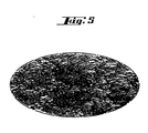
- the electrode 1 has a directionally structured on the flat end face 3 Contact area.
- the individual asymmetrical scaly elevations have one Preferred orientation, that of the fastening direction 11 for clockwise screws equivalent.
- the fastening direction 11 should be understood to mean that shown in FIG. 4
- Electrode 1 and a screwed-in nipple are fixed. From above it becomes one further electrode, not shown, screwed on. This electrode turns Attachment in the direction of arrow 11. This process corresponds to that in Steelworks.
- the surface structure of the field V from FIG. 4 is enlarged in FIG. 5 shown.
- FIG. 5 shows the partial enlargement of the contact area 3 of the electrode 1 from FIG. 4 Field V.
- the model representation of the directionally structured is shown Electrodes face.
Landscapes
- Physics & Mathematics (AREA)
- Engineering & Computer Science (AREA)
- Plasma & Fusion (AREA)
- Discharge Heating (AREA)
- Furnace Details (AREA)
- Inert Electrodes (AREA)
- Electrotherapy Devices (AREA)
- Prostheses (AREA)
- Pressure Welding/Diffusion-Bonding (AREA)
- Water Treatment By Electricity Or Magnetism (AREA)
Abstract
Description
Bezogen auf das Verschrauben von Strängen aus Kohlenstoff-Elektroden sei darauf hingewiesen, dass makroskopische Noppen auf den Kontaktflächen der Elektroden oder Nippel wegen des keramischen und damit spröden Charakters der Kohlenstoffe beim Verschrauben wegplatzen würden. Möglicherweise würden sogar beträchtliche Stücke aus den Stirnflächen der Strangelemente springen.
Bezogen auf das Verschrauben von Strängen aus Kohlenstoff-Elektroden sei darauf hingewiesen, dass makroskopische Noppen auf den Kontaktflächen der Elektroden oder Nippel wegen des keramischen und damit spröden Charakters der Kohlenstoffe beim Verschrauben wegplatzen würden. Möglicherweise würden sogar beträchtliche Stücke aus den Stirnflächen der Strangelemente springen.
Dieses Prinzip soll in erster Linie die (tangentialen) Spannungsspitzen in der Elektrodenschachtel vermindern und Elektrodenbrüche verhüten womit es sich vollständig von dem erfindungsgemäßen Prinzip der Verminderung der Lockerung von verschraubten Kohlenstoffelektroden unterscheidet.
Eine weitere Aufgabe bestand darin, das messbare Lösemoment zwischen benachbarten Elementen eines Elektrodenstranges zu erhöhen.
Die weitere Aufgabe wird gemäß dem kennzeichnenden Teil des Anspruches 10 dadurch gelöst, dass die gleichartigen tangentialen Richtungen - entweder Befestigungsoder Lösungsrichtung der Schraubverbindung - der gerichtet strukturierten Kontaktflächen von zwei benachbarten Elementen eines Elektrodenstranges jeweils gegensinnig ausgerichtet sind.
Ein wesentlicher Vorteil der Erfindung besteht in den kleinen Dimensionen der asymmetrischen Noppen bzw. Schuppen auf den Kontaktflächen. Kleine Schuppen verursachen bei Verformungen während des Verschraubvorganges keine Ausplatzungen an den keramischen Körpern der Elektroden oder Nippel aus Kohlenstoff oder Graphit.
Ein weiterer Vorteil besteht darin, dass übliche Anpressdrucke von benachbarten Elementen in den Elektrodensträngen genügen, um eine Lockerung zu unterdrücken. Bei den üblichen Anpressdrucken verhaken sich die gegensinnig ausgerichteten schuppigen Erhebungen benachbarter Elemente im Strang.
- Die Enden einer Elektrode werden auch mit Stirnseite bezeichnet.
- Eine Elektrode hat eine zylindrische Mantelfläche und beidseitig je eine senkrecht zur Elektrodenachse angeordnete Stirnfläche.
- Eine Schachtel ist eine koaxial angeordnete Vertiefung in der Stirnseite einer Elektrode. In die koaxialen Innenwände einer Schachtel sind meist zylindrische oder konische Innengewinde eingearbeitet.
- Ein Nippel ist eine zylindrische oder doppelkonische Schraube mit beidseitig je einer senkrecht zur Nippelachse angeordneten Stirnfläche. Ein Nippel wird zwecks Verbindung zweier Elektroden etwa je zur Hälfte in eine Schachtel benachbarter Elektroden eingeschraubt.
- Ein Preset besteht aus einer Elektrode und einem in eine Schachtel der Elektrode zur Hälfte darin eingeschraubten Nippel.
- Manche Elektroden haben nur an einer Stirnseite eine Schachtel und an der anderen Stirnseite ein nach außen weisendes koaxiales Gewinde. Ein solches nach außen weisendes koaxiales Gewinde wird als integrierter Nippel bezeichnet.
- Nicht nur eine Elektrode und ein Nippel haben Stirnflächen sondern auch der integrierte Nippel hat eine äußere, senkrecht zur Nippelachse angeordnete Stirnfläche.
- Unter den Kontaktflächen benachbarter Elemente werden solche Kontaktflächen verstanden, die durch Verschrauben der Elemente gegeneinander gedrückt werden.
- Ideal ausgebildete Kontaktflächen sind solche gekrümmte oder ebene Flächen, die nicht von Erhebungen oder Vertiefungen gestört sind.
- Sind asymmetrische, schuppige Erhebungen gleichsinnig auf einer ideal ausgebildeten Kontaktfläche angeordnet, so wird diese Gesamtheit als gerichtete Oberflächenstruktur bezeichnet.
- Wenn eine Kontaktfläche in einem Strang aus Kohlenstoffelektroden eine gerichtete Oberflächenstruktur aufweist, so ist es nicht unwesentlich, in welcher Richtung die Kontaktfläche genutzt wird. In einem ersten Fall kann die gerichtete Oberflächenstruktur vom flachen Anstieg zum steilen Anstieg der Flanken der schuppige Erhebungen durchlaufen werden, in einem zweiten Fall kann die gerichtete Oberflächenstruktur vom steilen Anstieg zum flachen Anstieg der Flanken der schuppige Erhebungen durchlaufen werden. Im ersten Fall ist der Widerstand - unter Beachtung sinnvoller Randbedingungen bei den beanspruchten geringen Höhen der schuppigen Erhebungen - gegen eine Bewegung über die gerichtete Oberflächenstruktur geringer als im zweiten Fall. Eine im wesentlichen senkrecht zu den beiden erstgenannten Bewegungen verlaufende Bewegung über die gerichtete Oberflächenstruktur wird für diese Betrachtungen nicht benötigt. Es ist nun zweckmäßig, bei rechtsdrehenden Schrauben die gerichtete Oberflächenstruktur so zu orientieren, dass bei einer Rechtsdrehung (Befestigung der Schraubverbindung) die gerichtete Oberflächenstruktur vom flachen Anstieg zum steilen Anstieg der Flanken der schuppige Erhebungen durchlaufen wird, was dem o. g. ersten Fall - mit niedrigem Widerstand - entspricht. Diese Orientierung der Oberflächenstruktur wird mit dieser Schraubbewegung als Befestigungsrichtung bezeichnet.
- Wird die rechtsdrehende Schraube bei gleich ausgerichteter Oberflächenstruktur nach links gedreht (Lösung der Schraubverbindung), was dem o. g. zweiten Fall - mit hohem Widerstand - entspricht, so wird die Richtung dieser Schraubbewegung als Lösungsrichtung bezeichnet.
- Die schuppigen Erhebungen haben einen - bezogen auf die Längsachsen der meist zylindrischen Elemente eines Elektrodenstranges - im wesentlichen radial orientierten Kamm.
- Die Kammlänge einer schuppigen Erhebung wird durch die Projektion des üblicherweise unregelmäßigen Kammes auf einen von der Längsachse der meist zylindrischen Elemente eines Elektrodenstranges ausgehenden Radialstrahl definiert.
Die Kontaktflächen beider benachbarter Elemente sind gerichtet strukturiert. Die aufeinander treffenden gerichteten Oberflächenstrukturen der Kontaktflächen sind immer gegensinnig orientiert.
Es werden dann sichere oder sich nicht wieder lockernde Schraubverbindungen erreicht, wenn zwei Kriterien erfüllt sind: Erstens wenn der Anpressdruck benachbarter Kontaktflächen im Bereich von 0,1 bis 80N/mm2 liegt, zweitens wenn die gerichtet strukturierten, schuppigen Erhebungen über der ideal ausgebildeten Kontaktfläche in einem geringen Höhenbereich von einem bis hundert Mikrometern hervortreten. Es war nicht naheliegend, von den kleinen, schuppigen Erhebungen im zusammengeschraubten Zustand der Elemente eines Stranges eine wesentlich bessere Lockerungssicherung zu erwarten. Es hat sich gezeigt, daß die kleinen, schuppigen Erhebungen auch den mechanischen Belastungen der Vibrationen widerstehen.
Um die Sicherheit des Zusammenhaltes der Verschraubung zu charakterisieren, wurde die Verbindung anschließend wieder geöffnet und dabei das Lösemoment gemessen.
| Die angegebenen Werte gelten für Elektroden mit einem Durchmesser von 600 mm und für ein Anzugsmoment von 4000 Nm beim Verschrauben. | |||
| Maßnahme | Modifizierte Flächen | Lösemoment [Nm] | |
| Variante A | ohne Gleitmittel, ohne gerichtete Struktur der Kontaktflächen | keine | 6000 |
| Variante B | mit gerichteter Struktur der Kontaktflächen | Stirnflächen der Elektroden | 9000 |
| Variante C | mit Gleitmittel (0,1 mm Lagerfett arcanol 12V) | Stirnfläche Elektrode und Gewindeflächen Nippel | >12000 |
Zwar ergibt Variante C ein noch höheres Lösemoment als Variante B, dies ist aber nur mit Hilfe einer Zusatzbehandlung möglich. Demgegenüber wird bei Variante B das günstige Lösemoment ohne Zusatzbehandlung erreicht.
- Fig. 1
- einen Schnitt parallel zur Längsachse durch eine Elektrode 1 mit beidseitig in die Stirnflächen 3 eingebrachten Schachteln, jeweils mit zylindrischem Innengewinde, sowie Ansicht der Längsseite eines unabhängigen Nippels 2 mit zylindrischem Gewinde;
- Fig. 2
- eine Ansicht der Längsseite einer Elektrode 1 mit einem an einer Stirnseite 3 angeformten, integrierten koaxialen Nippel. An der anderen Stirnseite ist die Seitenansicht der Elektrode mit einem Schnitt parallel zur Längsachse aufgebrochen. Der Schnitt zeigt an dieser Stelle eine Schachtel mit konischem Innengewinde;
- Fig. 3
- einen Schnitt parallel zur Längsachse durch ein Preset 9, das aus einer Elektrode 1 mit konischen Schachteln und einem Nippel 2 mit doppelt-konischem Gewinde 5 besteht;
- Fig. 4
- eine räumliche Darstellung der Stirnfläche 3 einer Elektrode 1 mit gerichtet strukturierter Kontaktfläche;
- Fig. 5
- vergrößerte, modellhafte Darstellung einer gerichtet strukturierten Elektrodenstirnfläche 3 (Kontaktfläche).
Bei einem unabhängigen Nippel 2 gibt es als Kontaktflächen die Gewindeflächen 5 des Nippels 2.
Die beidseitigen Stirnflächen 6 des Nippels 2 sind keine Kontaktflächen.
Die äußere Stirnfläche 8 des integrierten koaxialen Nippels ist keine mit einer Gleitschicht zu versehende Kontaktfläche. Der Schachtelboden 10 der Elektrode ist keine Kontaktfläche.
- 1
- Elektrode
- 2
- Unabhängiger Nippel
- 3
- Stirnfläche der Elektrode
- 4
- Gewindeflächen der Elektrodenschachtel
- 5
- Gewindeflächen des Nippels
- 6
- Stirnfläche des Nippels
- 7
- Gewindeflächen des integrierten Nippels
- 8
- äußere Stirnfläche des integrierten Nippels
- 9
- Preset
- 10
- Schachtelboden
- 11
- Tangentiale Befestigungsrichtung für rechtsdrehendes Gewinde; die Befestigungsrichtung stimmt im wesentlichen mit der Richtung der gerichtet strukturierten Kontaktfläche überein
Claims (11)
- Elemente eines Elektrodenstranges, der aus Kohlenstoffelektroden (1) mit stirnseitigen Schachteln und Innengewinden (4) und aus je zwei solche Elektroden (1) verbindenden Kohlenstoff-Nippeln (2) besteht oder der aus Kohlenstoffelektroden (1) mit Schachtel und Innengewinde (4) an einer Stirnseite und integriertem Nippel an der anderen Stirnseite besteht, vorgesehen für einen Elektrodenstrang zum Einsatz in einem Lichtbogenofen zur Herstellung von hochschmelzenden Metallen, wobei die Elemente ideal ausgebildete Kontaktflächen mit daraus hervortretenden, gerichtet strukturierten, schuppigen Erhebungen haben, dadurch gekennzeichnet, dass
die gerichtet strukturierten, schuppigen Erhebungen über der ideal ausgebildeten Kontaktfläche in einem Höhenbereich von drei bis hundert Mikrometern hervortreten, und dass die benachbarten Kontaktflächen einer Schraubverbindung einen Anpressdruck im Bereich von 0,1 bis 80 N/mm2 haben. - Elemente eines Elektrodenstranges nach Anspruch 1 dadurch gekennzeichnet, dass die ideal ausgebildeten Kontaktflächen eben oder gekrümmt sind.
- Elemente eines Elektrodenstranges nach den Ansprüchen 1 und 2 dadurch gekennzeichnet, dass
die schuppigen Erhebungen auf den gerichtet strukturierten Kontaktflächen arteigenes Material der Elemente des Elektrodenstranges sind. - Elemente eines Elektrodenstranges nach einem oder mehreren der Ansprüche 1 bis 3 dadurch gekennzeichnet, dass
die schuppigen Erhebungen eine im wesentlichen asymmetrische, durch einen unterschiedlich steilen Anstieg der Flanken charakterisierte Gestalt haben, wobei die Flanken der schuppigen Erhebungen in der Befestigungsrichtung der Schraubverbindung einen im wesentlichen flachen Anstieg und in der entgegengesetzten Lösungsrichtung der Schraubverbindung einen im wesentlichen steilen Anstieg haben. - Elemente eines Elektrodenstranges nach einem oder mehreren der Ansprüche 1 bis 4 dadurch gekennzeichnet, dass
die höchsten Höhen einer schuppigen Erhebung als Spitze oder als im wesentlichen radial orientierter Kamm - bezogen auf die Längsachsen der meist zylindrischen Elemente eines Elektrodenstranges - ausgebildet sind. - Elemente eines Elektrodenstranges nach Anspruch 4 dadurch gekennzeichnet, dass jeweils der flache Anstieg aller schuppigen Erhebungen in der Befestigungsrichtung in einer Kontaktfläche - eines Elementes eines Elektrodenstranges gemäß Anspruch 1 - angeordnet ist.
- Elemente eines Elektrodenstranges nach einem oder mehreren der Ansprüche 1 bis 6 dadurch gekennzeichnet, dass
die schuppigen Erhebungen auf der jeweiligen Kontaktfläche statistisch verteilt sind. - Elemente eines Elektrodenstranges nach einem oder mehreren der Ansprüche 1 bis 6 dadurch gekennzeichnet, dass
die schuppigen Erhebungen die jeweilige ideal ausgebildete Kontaktfläche partiell bedecken oder in Form von Mustern angeordnet sind. - Elemente eines Elektrodenstranges nach einem oder mehreren der Ansprüche 1 bis 8 dadurch gekennzeichnet, dass die jeweiligen Kontaktflächen mindestens 100 Meter Kammlänge der schuppigen Erhebungen je Quadratmeter Kontaktfläche, vorzugsweise 300 Meter Kammlänge der schuppigen Erhebungen je Quadratmeter Kontaktfläche, enthalten.
- Benachbarte Elemente eines Elektrodenstranges nach einem oder mehreren der Ansprüche 1 bis 9 dadurch gekennzeichnet, dass
die gleichartigen tangentialen Richtungen - entweder Befestigungs- oder Lösungsrichtung der Schraubverbindung - der gerichtet strukturierten Kontaktflächen von zwei benachbarten Elementen eines Elektrodenstranges jeweils gegensinnig ausgerichtet sind. - Benachbarte Elemente eines Elektrodenstranges nach einem oder mehreren der Ansprüche 1 bis 12 dadurch gekennzeichnet, dass
eine Kohlenstoff-Elektrode (1) und ein Kohlenstoff-Nippel (2) zu einem Preset (9) zusammengefasst sind und dass die inneren Kontaktflächen des Preset (9) gerichtet strukturiert sind wobei die inneren Kontaktflächen aus den Gewindeflächen der Elektrodenschachtel (4) und des Nippels (5) bestehen.
Applications Claiming Priority (2)
| Application Number | Priority Date | Filing Date | Title |
|---|---|---|---|
| DE10302956 | 2003-01-24 | ||
| DE10302956A DE10302956B3 (de) | 2003-01-24 | 2003-01-24 | Kohlenstoffelektroden und deren Verbindungselemente mit gerichtet strukturierten Kontaktflächen |
Publications (2)
| Publication Number | Publication Date |
|---|---|
| EP1441570A1 true EP1441570A1 (de) | 2004-07-28 |
| EP1441570B1 EP1441570B1 (de) | 2006-11-02 |
Family
ID=32520109
Family Applications (1)
| Application Number | Title | Priority Date | Filing Date |
|---|---|---|---|
| EP04001404A Expired - Lifetime EP1441570B1 (de) | 2003-01-24 | 2004-01-23 | Kohlenstoffelektroden und deren Verbindungselemente mit gerichtet strukturierten Kontaktflächen |
Country Status (14)
| Country | Link |
|---|---|
| US (1) | US6925104B2 (de) |
| EP (1) | EP1441570B1 (de) |
| JP (1) | JP2004228091A (de) |
| CN (1) | CN100534241C (de) |
| AT (1) | ATE344611T1 (de) |
| BR (1) | BRPI0400112A (de) |
| CA (1) | CA2455800A1 (de) |
| DE (2) | DE10302956B3 (de) |
| ES (1) | ES2276173T3 (de) |
| MX (1) | MXPA04000682A (de) |
| MY (1) | MY127514A (de) |
| RU (1) | RU2004102031A (de) |
| TW (1) | TW200428911A (de) |
| ZA (1) | ZA200400472B (de) |
Families Citing this family (6)
| Publication number | Priority date | Publication date | Assignee | Title |
|---|---|---|---|---|
| PL2373121T3 (pl) * | 2007-04-09 | 2014-01-31 | Graftech Int Holdings Inc | Monolityczne elektrody grafitowe o dużej długości |
| US20090180512A1 (en) * | 2008-01-16 | 2009-07-16 | Michael Frastaci | Compressible Electrode End Face |
| US9497804B2 (en) | 2010-07-01 | 2016-11-15 | Graftech International Holdings Inc. | Graphite electrode |
| CN109378614A (zh) * | 2018-09-29 | 2019-02-22 | 闫永超 | 一种无弹性铜舌片的新型电插座 |
| CN115709266A (zh) * | 2022-12-09 | 2023-02-24 | 宝武特冶航研科技有限公司 | 一种细长型自耗电极坯的制作方法 |
| US20250212299A1 (en) * | 2023-12-21 | 2025-06-26 | Graftech International Holdings Inc. | Monitoring system for an electrode coupling device |
Citations (5)
| Publication number | Priority date | Publication date | Assignee | Title |
|---|---|---|---|---|
| US2135637A (en) * | 1935-04-26 | 1938-11-08 | Standard Pressed Steel Co | Setscrew |
| US2867786A (en) * | 1955-04-29 | 1959-01-06 | Conradty Fa C | Mounting means for carbon electrodes or graphite electrodes |
| US4273175A (en) * | 1979-04-04 | 1981-06-16 | The Lamson & Sessions Co. | Thread convolution |
| EP0056127A2 (de) * | 1981-01-14 | 1982-07-21 | Arc Technologies Systems, Ltd. | Elektrode, insbesondere für Lichtbogenöfen oder die Schmelzflusselektrolyse |
| US4729689A (en) * | 1984-12-13 | 1988-03-08 | Union Carbide Corporation | Electrode member and process for the production thereof |
Family Cites Families (14)
| Publication number | Priority date | Publication date | Assignee | Title |
|---|---|---|---|---|
| US2527294A (en) * | 1949-01-03 | 1950-10-24 | Great Lakes Carbon Corp | Carbon electrode |
| FR1194249A (de) * | 1957-04-11 | 1959-11-06 | ||
| US3134616A (en) * | 1958-11-07 | 1964-05-26 | Siemens Planiawerke Ag | Double-conical nipple joint for carbon electrodes |
| US4152533A (en) * | 1978-04-27 | 1979-05-01 | Great Lakes Carbon Corporation | Electrode joint |
| US4375340A (en) * | 1980-03-21 | 1983-03-01 | Great Lakes Carbon Corporation | Carbon electrode joint |
| DE3442316A1 (de) * | 1984-11-20 | 1986-05-22 | Sigri GmbH, 8901 Meitingen | Verbindung von graphit- und kohlenstoffelektroden |
| US4679206A (en) * | 1985-05-15 | 1987-07-07 | Union Carbide Corporation | Electrode joint thread form |
| US5190423A (en) | 1991-02-15 | 1993-03-02 | Ewing Paul E | Locking fastener |
| DE4137020C2 (de) * | 1991-11-11 | 1994-09-08 | Jaeger Eberhard Gmbh | Selbstsicherndes Befestigungselement, z. B. Schraube oder Mutter |
| US5336015A (en) * | 1992-11-25 | 1994-08-09 | Ucar Carbon Technology Corporation | Self centering electrode joint |
| US5575582A (en) * | 1995-01-18 | 1996-11-19 | Ucar Carbon Technology Corporation | Fastening device for securing electrode joints |
| CN2298092Y (zh) * | 1997-05-23 | 1998-11-25 | 山东省生建八三厂 | 硅碳棒真空焊接炉电加热装置 |
| US6500022B2 (en) * | 2001-03-30 | 2002-12-31 | Ucar Carbon Company Inc. | Threaded pin for carbon electrodes |
| DE10253254B3 (de) * | 2002-11-15 | 2004-05-27 | Sgl Carbon Ag | Elektrodenverbindung mit beschichteten Kontaktflächen |
-
2003
- 2003-01-24 DE DE10302956A patent/DE10302956B3/de not_active Expired - Fee Related
-
2004
- 2004-01-20 CN CNB2004100067101A patent/CN100534241C/zh not_active Expired - Fee Related
- 2004-01-22 MX MXPA04000682A patent/MXPA04000682A/es active IP Right Grant
- 2004-01-22 ZA ZA2004/00472A patent/ZA200400472B/en unknown
- 2004-01-23 CA CA002455800A patent/CA2455800A1/en not_active Abandoned
- 2004-01-23 JP JP2004015077A patent/JP2004228091A/ja active Pending
- 2004-01-23 EP EP04001404A patent/EP1441570B1/de not_active Expired - Lifetime
- 2004-01-23 RU RU2004102031/15A patent/RU2004102031A/ru not_active Application Discontinuation
- 2004-01-23 ES ES04001404T patent/ES2276173T3/es not_active Expired - Lifetime
- 2004-01-23 BR BR0400112-5A patent/BRPI0400112A/pt not_active IP Right Cessation
- 2004-01-23 DE DE502004001868T patent/DE502004001868D1/de not_active Expired - Lifetime
- 2004-01-23 AT AT04001404T patent/ATE344611T1/de not_active IP Right Cessation
- 2004-01-26 US US10/765,600 patent/US6925104B2/en not_active Expired - Fee Related
- 2004-01-26 MY MYPI20040203A patent/MY127514A/en unknown
- 2004-01-27 TW TW093101767A patent/TW200428911A/zh unknown
Patent Citations (5)
| Publication number | Priority date | Publication date | Assignee | Title |
|---|---|---|---|---|
| US2135637A (en) * | 1935-04-26 | 1938-11-08 | Standard Pressed Steel Co | Setscrew |
| US2867786A (en) * | 1955-04-29 | 1959-01-06 | Conradty Fa C | Mounting means for carbon electrodes or graphite electrodes |
| US4273175A (en) * | 1979-04-04 | 1981-06-16 | The Lamson & Sessions Co. | Thread convolution |
| EP0056127A2 (de) * | 1981-01-14 | 1982-07-21 | Arc Technologies Systems, Ltd. | Elektrode, insbesondere für Lichtbogenöfen oder die Schmelzflusselektrolyse |
| US4729689A (en) * | 1984-12-13 | 1988-03-08 | Union Carbide Corporation | Electrode member and process for the production thereof |
Also Published As
| Publication number | Publication date |
|---|---|
| CN1551684A (zh) | 2004-12-01 |
| ZA200400472B (en) | 2005-05-25 |
| BRPI0400112A (pt) | 2004-12-28 |
| DE10302956B3 (de) | 2004-07-22 |
| DE502004001868D1 (de) | 2006-12-14 |
| CN100534241C (zh) | 2009-08-26 |
| MY127514A (en) | 2006-12-29 |
| ES2276173T3 (es) | 2007-06-16 |
| RU2004102031A (ru) | 2005-07-10 |
| TW200428911A (en) | 2004-12-16 |
| CA2455800A1 (en) | 2004-07-24 |
| ATE344611T1 (de) | 2006-11-15 |
| US6925104B2 (en) | 2005-08-02 |
| US20040192088A1 (en) | 2004-09-30 |
| JP2004228091A (ja) | 2004-08-12 |
| MXPA04000682A (es) | 2005-07-25 |
| EP1441570B1 (de) | 2006-11-02 |
| PL364548A1 (en) | 2004-07-26 |
Similar Documents
| Publication | Publication Date | Title |
|---|---|---|
| DE3872526T2 (de) | Werkzeug fuer ein protheseelement. | |
| DE602004006939T2 (de) | Schraubverbindung für Kohlenstoff- und/oder Graphitelektrode | |
| DE69010650T2 (de) | Vorrichtung zum geraderichten, befestigen, zusammendrücken und ausdehnen der wirbelsäule. | |
| EP0956828A2 (de) | Osteosynthesevorrichtung mit Korrekturstab | |
| DE2548591B1 (de) | Gelenkendoprothese | |
| DE4208548A1 (de) | Steckschluesselmaul | |
| EP1635720A1 (de) | Elastisch schliessende doppelbacken zu externem fixateur | |
| DE9311984U1 (de) | Befestigungselement, insbesondere Mutter oder Schraube, und Werkzeug zur Betätigung | |
| EP1601301A1 (de) | Einschraubbares knochenimplantat | |
| DE69607462T2 (de) | Selbstsichernde Mutter | |
| EP0260671B1 (de) | Schläger für Ballspiele, insbesondere Tennisspiele, sowie Bespannvorrichtung hierzu | |
| DE69621360T2 (de) | Kohlenstoffelektrode | |
| DE10336537B3 (de) | Implantatteil für ein Zahnimplantat | |
| DE3144901C2 (de) | Elektrisch isolierte Verbindung zwischen zwei gleichachsig angeordneten, stabförmigen Elementen aus Metall insbesondere Schraubendreher | |
| DE10302956B3 (de) | Kohlenstoffelektroden und deren Verbindungselemente mit gerichtet strukturierten Kontaktflächen | |
| DE10205635B4 (de) | Werkzeugverbindung | |
| AT393542B (de) | Verbindung fuer bauteile aus unterschiedlichen materialien | |
| EP0940227B1 (de) | Werkzeug zum Vernieten von Blindnietmuttern | |
| EP4353666B1 (de) | Anschlagpunkt | |
| DE60308278T2 (de) | Krimpmutter mit selbsthemmendem Gewindeeinsatz | |
| WO2004092542A1 (de) | Walzenförmiger schneidkörper | |
| DE3525956C2 (de) | ||
| EP1157758A1 (de) | Vorrichtung zum Entfernen von Beulen aus Blech | |
| DE1048369B (de) | ||
| DE29810003U1 (de) | Hilfsvorrichtung zur Montage bzw. Demontage von Fahrzeugrädern |
Legal Events
| Date | Code | Title | Description |
|---|---|---|---|
| PUAI | Public reference made under article 153(3) epc to a published international application that has entered the european phase |
Free format text: ORIGINAL CODE: 0009012 |
|
| AK | Designated contracting states |
Kind code of ref document: A1 Designated state(s): AT BE BG CH CY CZ DE DK EE ES FI FR GB GR HU IE IT LI LU MC NL PT RO SE SI SK TR |
|
| AX | Request for extension of the european patent |
Extension state: AL LT LV MK |
|
| 17P | Request for examination filed |
Effective date: 20050128 |
|
| 17Q | First examination report despatched |
Effective date: 20050304 |
|
| AKX | Designation fees paid |
Designated state(s): AT BE BG CH CY CZ DE DK EE ES FI FR GB GR HU IE IT LI LU MC NL PT RO SE SI SK TR |
|
| GRAP | Despatch of communication of intention to grant a patent |
Free format text: ORIGINAL CODE: EPIDOSNIGR1 |
|
| GRAS | Grant fee paid |
Free format text: ORIGINAL CODE: EPIDOSNIGR3 |
|
| GRAA | (expected) grant |
Free format text: ORIGINAL CODE: 0009210 |
|
| AK | Designated contracting states |
Kind code of ref document: B1 Designated state(s): AT BE BG CH CY CZ DE DK EE ES FI FR GB GR HU IE IT LI LU MC NL PT RO SE SI SK TR |
|
| PG25 | Lapsed in a contracting state [announced via postgrant information from national office to epo] |
Ref country code: IE Free format text: LAPSE BECAUSE OF FAILURE TO SUBMIT A TRANSLATION OF THE DESCRIPTION OR TO PAY THE FEE WITHIN THE PRESCRIBED TIME-LIMIT Effective date: 20061102 Ref country code: CZ Free format text: LAPSE BECAUSE OF FAILURE TO SUBMIT A TRANSLATION OF THE DESCRIPTION OR TO PAY THE FEE WITHIN THE PRESCRIBED TIME-LIMIT Effective date: 20061102 Ref country code: SI Free format text: LAPSE BECAUSE OF FAILURE TO SUBMIT A TRANSLATION OF THE DESCRIPTION OR TO PAY THE FEE WITHIN THE PRESCRIBED TIME-LIMIT Effective date: 20061102 Ref country code: FI Free format text: LAPSE BECAUSE OF FAILURE TO SUBMIT A TRANSLATION OF THE DESCRIPTION OR TO PAY THE FEE WITHIN THE PRESCRIBED TIME-LIMIT Effective date: 20061102 Ref country code: SK Free format text: LAPSE BECAUSE OF FAILURE TO SUBMIT A TRANSLATION OF THE DESCRIPTION OR TO PAY THE FEE WITHIN THE PRESCRIBED TIME-LIMIT Effective date: 20061102 Ref country code: RO Free format text: LAPSE BECAUSE OF FAILURE TO SUBMIT A TRANSLATION OF THE DESCRIPTION OR TO PAY THE FEE WITHIN THE PRESCRIBED TIME-LIMIT Effective date: 20061102 Ref country code: NL Free format text: LAPSE BECAUSE OF FAILURE TO SUBMIT A TRANSLATION OF THE DESCRIPTION OR TO PAY THE FEE WITHIN THE PRESCRIBED TIME-LIMIT Effective date: 20061102 |
|
| REG | Reference to a national code |
Ref country code: GB Ref legal event code: FG4D Free format text: NOT ENGLISH |
|
| REG | Reference to a national code |
Ref country code: IE Ref legal event code: FG4D Free format text: LANGUAGE OF EP DOCUMENT: GERMAN |
|
| REG | Reference to a national code |
Ref country code: CH Ref legal event code: EP |
|
| REF | Corresponds to: |
Ref document number: 502004001868 Country of ref document: DE Date of ref document: 20061214 Kind code of ref document: P |
|
| PG25 | Lapsed in a contracting state [announced via postgrant information from national office to epo] |
Ref country code: MC Free format text: LAPSE BECAUSE OF NON-PAYMENT OF DUE FEES Effective date: 20070131 |
|
| PG25 | Lapsed in a contracting state [announced via postgrant information from national office to epo] |
Ref country code: SE Free format text: LAPSE BECAUSE OF FAILURE TO SUBMIT A TRANSLATION OF THE DESCRIPTION OR TO PAY THE FEE WITHIN THE PRESCRIBED TIME-LIMIT Effective date: 20070202 Ref country code: DK Free format text: LAPSE BECAUSE OF FAILURE TO SUBMIT A TRANSLATION OF THE DESCRIPTION OR TO PAY THE FEE WITHIN THE PRESCRIBED TIME-LIMIT Effective date: 20070202 Ref country code: BG Free format text: LAPSE BECAUSE OF FAILURE TO SUBMIT A TRANSLATION OF THE DESCRIPTION OR TO PAY THE FEE WITHIN THE PRESCRIBED TIME-LIMIT Effective date: 20070202 |
|
| PG25 | Lapsed in a contracting state [announced via postgrant information from national office to epo] |
Ref country code: PT Free format text: LAPSE BECAUSE OF FAILURE TO SUBMIT A TRANSLATION OF THE DESCRIPTION OR TO PAY THE FEE WITHIN THE PRESCRIBED TIME-LIMIT Effective date: 20070402 |
|
| NLV1 | Nl: lapsed or annulled due to failure to fulfill the requirements of art. 29p and 29m of the patents act | ||
| GBV | Gb: ep patent (uk) treated as always having been void in accordance with gb section 77(7)/1977 [no translation filed] |
Effective date: 20061102 |
|
| ET | Fr: translation filed | ||
| REG | Reference to a national code |
Ref country code: ES Ref legal event code: FG2A Ref document number: 2276173 Country of ref document: ES Kind code of ref document: T3 |
|
| REG | Reference to a national code |
Ref country code: IE Ref legal event code: FD4D |
|
| PLBE | No opposition filed within time limit |
Free format text: ORIGINAL CODE: 0009261 |
|
| STAA | Information on the status of an ep patent application or granted ep patent |
Free format text: STATUS: NO OPPOSITION FILED WITHIN TIME LIMIT |
|
| 26N | No opposition filed |
Effective date: 20070803 |
|
| PG25 | Lapsed in a contracting state [announced via postgrant information from national office to epo] |
Ref country code: GB Free format text: LAPSE BECAUSE OF FAILURE TO SUBMIT A TRANSLATION OF THE DESCRIPTION OR TO PAY THE FEE WITHIN THE PRESCRIBED TIME-LIMIT Effective date: 20061102 |
|
| BERE | Be: lapsed |
Owner name: SGL CARBON A.G. Effective date: 20070131 |
|
| PG25 | Lapsed in a contracting state [announced via postgrant information from national office to epo] |
Ref country code: BE Free format text: LAPSE BECAUSE OF NON-PAYMENT OF DUE FEES Effective date: 20070131 |
|
| PG25 | Lapsed in a contracting state [announced via postgrant information from national office to epo] |
Ref country code: GR Free format text: LAPSE BECAUSE OF FAILURE TO SUBMIT A TRANSLATION OF THE DESCRIPTION OR TO PAY THE FEE WITHIN THE PRESCRIBED TIME-LIMIT Effective date: 20070203 |
|
| PG25 | Lapsed in a contracting state [announced via postgrant information from national office to epo] |
Ref country code: AT Free format text: LAPSE BECAUSE OF NON-PAYMENT OF DUE FEES Effective date: 20070123 |
|
| REG | Reference to a national code |
Ref country code: CH Ref legal event code: PL |
|
| PG25 | Lapsed in a contracting state [announced via postgrant information from national office to epo] |
Ref country code: CH Free format text: LAPSE BECAUSE OF NON-PAYMENT OF DUE FEES Effective date: 20080131 Ref country code: LI Free format text: LAPSE BECAUSE OF NON-PAYMENT OF DUE FEES Effective date: 20080131 |
|
| PG25 | Lapsed in a contracting state [announced via postgrant information from national office to epo] |
Ref country code: EE Free format text: LAPSE BECAUSE OF FAILURE TO SUBMIT A TRANSLATION OF THE DESCRIPTION OR TO PAY THE FEE WITHIN THE PRESCRIBED TIME-LIMIT Effective date: 20061102 |
|
| PG25 | Lapsed in a contracting state [announced via postgrant information from national office to epo] |
Ref country code: CY Free format text: LAPSE BECAUSE OF FAILURE TO SUBMIT A TRANSLATION OF THE DESCRIPTION OR TO PAY THE FEE WITHIN THE PRESCRIBED TIME-LIMIT Effective date: 20061102 Ref country code: LU Free format text: LAPSE BECAUSE OF NON-PAYMENT OF DUE FEES Effective date: 20070123 |
|
| PG25 | Lapsed in a contracting state [announced via postgrant information from national office to epo] |
Ref country code: TR Free format text: LAPSE BECAUSE OF FAILURE TO SUBMIT A TRANSLATION OF THE DESCRIPTION OR TO PAY THE FEE WITHIN THE PRESCRIBED TIME-LIMIT Effective date: 20061102 Ref country code: HU Free format text: LAPSE BECAUSE OF FAILURE TO SUBMIT A TRANSLATION OF THE DESCRIPTION OR TO PAY THE FEE WITHIN THE PRESCRIBED TIME-LIMIT Effective date: 20070503 |
|
| PGFP | Annual fee paid to national office [announced via postgrant information from national office to epo] |
Ref country code: DE Payment date: 20110131 Year of fee payment: 8 Ref country code: FR Payment date: 20110202 Year of fee payment: 8 Ref country code: IT Payment date: 20110127 Year of fee payment: 8 |
|
| PGFP | Annual fee paid to national office [announced via postgrant information from national office to epo] |
Ref country code: ES Payment date: 20110125 Year of fee payment: 8 |
|
| REG | Reference to a national code |
Ref country code: FR Ref legal event code: ST Effective date: 20120928 |
|
| PG25 | Lapsed in a contracting state [announced via postgrant information from national office to epo] |
Ref country code: DE Free format text: LAPSE BECAUSE OF NON-PAYMENT OF DUE FEES Effective date: 20120801 |
|
| REG | Reference to a national code |
Ref country code: DE Ref legal event code: R119 Ref document number: 502004001868 Country of ref document: DE Effective date: 20120801 |
|
| PG25 | Lapsed in a contracting state [announced via postgrant information from national office to epo] |
Ref country code: IT Free format text: LAPSE BECAUSE OF NON-PAYMENT OF DUE FEES Effective date: 20120123 |
|
| PG25 | Lapsed in a contracting state [announced via postgrant information from national office to epo] |
Ref country code: FR Free format text: LAPSE BECAUSE OF NON-PAYMENT OF DUE FEES Effective date: 20120131 |
|
| REG | Reference to a national code |
Ref country code: ES Ref legal event code: FD2A Effective date: 20130705 |
|
| PG25 | Lapsed in a contracting state [announced via postgrant information from national office to epo] |
Ref country code: ES Free format text: LAPSE BECAUSE OF NON-PAYMENT OF DUE FEES Effective date: 20120124 |