EP1441168A1 - Tapping device with valve - Google Patents
Tapping device with valve Download PDFInfo
- Publication number
- EP1441168A1 EP1441168A1 EP04001238A EP04001238A EP1441168A1 EP 1441168 A1 EP1441168 A1 EP 1441168A1 EP 04001238 A EP04001238 A EP 04001238A EP 04001238 A EP04001238 A EP 04001238A EP 1441168 A1 EP1441168 A1 EP 1441168A1
- Authority
- EP
- European Patent Office
- Prior art keywords
- valve
- spindle
- tapping fitting
- fitting according
- thread
- Prior art date
- Legal status (The legal status is an assumption and is not a legal conclusion. Google has not performed a legal analysis and makes no representation as to the accuracy of the status listed.)
- Granted
Links
Images
Classifications
-
- F—MECHANICAL ENGINEERING; LIGHTING; HEATING; WEAPONS; BLASTING
- F16—ENGINEERING ELEMENTS AND UNITS; GENERAL MEASURES FOR PRODUCING AND MAINTAINING EFFECTIVE FUNCTIONING OF MACHINES OR INSTALLATIONS; THERMAL INSULATION IN GENERAL
- F16L—PIPES; JOINTS OR FITTINGS FOR PIPES; SUPPORTS FOR PIPES, CABLES OR PROTECTIVE TUBING; MEANS FOR THERMAL INSULATION IN GENERAL
- F16L47/00—Connecting arrangements or other fittings specially adapted to be made of plastics or to be used with pipes made of plastics
- F16L47/26—Connecting arrangements or other fittings specially adapted to be made of plastics or to be used with pipes made of plastics for branching pipes; for joining pipes to walls; Adaptors therefor
- F16L47/34—Tapping pipes, i.e. making connections through walls of pipes while carrying fluids; Fittings therefor
- F16L47/345—Tapping pipes, i.e. making connections through walls of pipes while carrying fluids; Fittings therefor making use of attaching means embracing the pipe
Definitions
- the invention relates to a valve tapping fitting, with a housing which with a Pipeline is connectable and that a valve socket and a branch nozzle opening into this has, a valve body and a tool for Cutting the pipeline axially displaceable by means of a spindle connected to it in a rotationally fixed manner are arranged, and with a valve bushing in the valve stub into which a guide ring is axially fixed, with the spindle passing through the guide ring.
- valve tapping fitting is known from DE 42 17 982 C2.
- the valve bush is provided with an internal thread, which is essentially over their entire Extends height and in which the tool engages with an external thread and thus guided becomes.
- these threads are fine threads in order to To keep torque when cutting the pipe as low as possible, shows nevertheless this technical concept has a high drilling torque. As a result of the fine thread, the Drilling continues a large number of turns.
- valve tapping fitting is known from EP 1 035 367 B1.
- the valve body and the tool is arranged rotatable relative to one another.
- the valve body, the one with The tool is almost completely surrounded by a non-rotatable but axially displaceable spindle Provide thread for receiving the spindle, so that the tool when turning the spindle a combined rotation and translation movement, but the valve body only a pure linear Movement.
- DE 42 17 982 C2 the thread of the valve bushing for guiding the tool, this is essentially done in EP 1 035 367 B1 through the design of the otherwise thread-free housing.
- Multi-speed spindle drives have been known for a long time, an example is shown in DE 35 02 523 A1. They are usually used when there is a large rotation of the spindle axial movements are required. So far, however, they have been with a valve tapping arm has not been used because of the problem of guiding the ripping tool the drill pipe cannot be solved satisfactorily.
- valve tapping valve of the aforementioned To design genus so that the disadvantages of a fine thread, especially high Tapping torque and high number of revolutions can be avoided.
- the spindle has a multi-start thread, which in a correspondingly designed internal thread of the guide ring engages, and that at least a groove running in the axial direction of the spindle is provided and in each groove one in the valve stub directly or indirectly held guide pin engages non-positively.
- the fine thread can be designed both on the tool and in the guide bush omitted.
- the guide pin or pins act as a driver, which is only the combined one enable rotational and translational movement.
- the multi-start thread preferably extends over the entire length of the spindle.
- annular body is inserted into the valve bushing, in the annular space of which at least one guide pin is fixed, it being possible for the guide pin to be provided is pressed into a groove in the annular space of the ring body.
- two diametrically opposite grooves on the spindle and correspondingly two guide pins can be provided.
- the ring body is in one piece with an actuating approach for the Rotational movement of the spindle is formed.
- the guide ring which also serves as an upper end stop for the tool, can be used in have upstanding stop pins in the axial direction of the ring body, which if necessary can have a rounded contact surface.
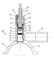
- FIG. 1 shows a section through an embodiment of a valve tapping fitting of the present Invention. It has a housing 10 made of plastic with a valve stub 14, into which a branch pipe 16 opens for connecting a branch line.
- the housing 10 furthermore, facing a tube, has a saddle 12, in the inner surface of which one Heating winding 18 is arranged.
- This heating winding 18 is concentric in a known manner to the axis of the valve stub 14.
- the saddle 12 is to be fastened to the outer surface of a tube by means of screws, with With the help of the heating winding 18 there is a tight connection with the tube.
- valve bushing 20 extends over a substantial part of the total height of the valve stub 14 and has an opening in the region of the branch connector 16. At her bottom At the end it extends practically to the saddle 12 in the immediate vicinity of the outer surface of the tube, where a valve seat 24 is integrated into the valve bushing 20.
- the valve connector 14 is closed at its upper free end by a cap 26, through which a spindle 50 is guided.
- a spindle 50 For sealing this axially displaceable spindle 50 these are surrounded by an annular body 70 which is inserted into the valve stub 14.
- the annular body 70 contains at least the outside one, expediently two seals 72, 74, which are each arranged in an annular groove.
- one piece connected to the annular body 70 is an actuating attachment 80 for the rotary movement the spindle 50, which can be designed in the usual way as a square.
- Another sealing ring 28 lies over a flange 76 of the ring body 70.
- the ring body 70 with the actuating projection 80 is hollow cylindrical, the Spindle 50 lies in this cavity.
- the spindle 50 described in more detail below is passed through a guide ring 60 which is firmly inserted into the valve stub 14 is screwed to it, for example.
- a valve body 30 and a tool 40 for example a drill, non-rotatably by means of a pin passing through the valve body 30 and the spindle 50.
- On Sealing ring 34 below the valve body 30 ensures the valve tapping valve in the closed state for the medium-tight seal on the valve seat 24.
- the tool 40 has a cutting edge 42 in a known manner.
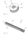
- Figure 2 shows the guide ring 60, which by means of an external thread 62 in the valve socket 14 ( Figure 1) is screwed. In the area of the external thread 2, two are diametrically opposed to one another Opposing stop pins 64, 66 housed in grooves, which if necessary can have rounded contact surfaces at their exposed end.
- the guide ring 60 also has a multiple thread, for example three or four thread, internal thread 68 that corresponds to the multi-start thread of the spindle.
- FIG. 3 shows a perspective view of a spindle 50, as is the case with the present invention is used.
- the spindle 50 is with a four-thread thread 52, which extends essentially over the entire Length of the spindle 50 extends.
- On the saddle 12 (FIG. 1) facing in the installed state At the end of the spindle 50 there is a bore 54 through which the pin 32 (FIG. 1) is secured of the valve body 30 or the tool 40 is guided.
- the longitudinal grooves are part of the guidance of the spindle 50.
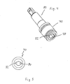
- FIG. 4 shows a perspective view of the ring body 70 with an actuating attachment attached to it 80.
- the ring body 70 In the hollow cylindrical interior of the ring body 70 are diametrically opposed to each other opposite grooves 78, 82 attached, which extend almost the entire length of the Extend ring body 70.
- These grooves 78, 82 are formed in cross section so that they Guide pins 84, 86 are press-fit as shown in the schematic plan view of the open end of the ring body 70 can be seen in Figure 5.
- the exposed cross section of the guide pins 84, 86 is designed so that it non-positively into the longitudinal grooves 56 of the spindle 50 ( Figure 3) protrudes.
Abstract
Description
Die Erfindung betrifft eine Ventil-Anbohrarmatur, mit einem Gehäuse, welches mit einer Rohrleitung verbindbar ist und das einen Ventilstutzen und einen in diesen mündenden Abzweigstutzen aufweist, wobei in dem Ventilstutzen ein Ventilkörper und ein Werkzeug zum Auftrennen der Rohrleitung mittels einer mit diesen drehfest verbundenen Spindel axial verschiebbar angeordnet sind, und mit einer Ventilbuchse in dem Ventilstutzen, in die ein Führungsring axial fest eingesetzt ist, wobei die Spindel den Führungsring durchsetzt. The invention relates to a valve tapping fitting, with a housing which with a Pipeline is connectable and that a valve socket and a branch nozzle opening into this has, a valve body and a tool for Cutting the pipeline axially displaceable by means of a spindle connected to it in a rotationally fixed manner are arranged, and with a valve bushing in the valve stub into which a guide ring is axially fixed, with the spindle passing through the guide ring.
Eine solche Ventil-Anbohrarmatur ist aus der DE 42 17 982 C2 bekannt. Die Ventilbuchse ist dabei mit einem Innengewinde versehen, welches sich im wesentlichen über ihre gesamte Höhe erstreckt und in welches das Werkzeug mit einem Außengewinde eingreift und so geführt wird. Diese Gewinde sind in der praktischen Ausgestaltung Feingewinde, um das Drehmoment beim Auftrennen des Rohres so gering wie möglich zu halten, trotzdem zeigt dieses technische Konzept ein hohes Anbohrmoment. Infolge des Feingewindes fordert der Bohrvorgang weiterhin eine große Anzahl von Drehungen.Such a valve tapping fitting is known from DE 42 17 982 C2. The valve bush is provided with an internal thread, which is essentially over their entire Extends height and in which the tool engages with an external thread and thus guided becomes. In practical terms, these threads are fine threads in order to To keep torque when cutting the pipe as low as possible, shows nevertheless this technical concept has a high drilling torque. As a result of the fine thread, the Drilling continues a large number of turns.
Eine weitere Ventil-Anbohrarmatur ist aus der EP 1 035 367 B1 bekannt. Hier sind der Ventilkörper
und das Werkzeug zueinander verdrehbar angeordnet. Der Ventilkörper, der eine mit
dem Werkzeug drehfeste, aber axial verschiebbare Spindel fast völlig umgibt, ist mit einem
Gewinde zur Aufnahme der Spindel versehen, so daß bei Drehung der Spindel das Werkzeug
eine kombinierte Dreh- und Translationsbewegung, der Ventilkörper aber nur eine reine lineare
Bewegung ausführt. Während bei der DE 42 17 982 C2 das Gewinde der Ventilbuchse für
die Führung des Werkzeuges sorgt, geschieht dies bei der EP 1 035 367 B1 im wesentlichen
durch die Ausgestaltung des ansonsten gewindefreien Gehäuses.Another valve tapping fitting is known from EP 1 035 367 B1. Here are the valve body
and the tool is arranged rotatable relative to one another. The valve body, the one with
The tool is almost completely surrounded by a non-rotatable but axially displaceable spindle
Provide thread for receiving the spindle, so that the tool when turning the spindle
a combined rotation and translation movement, but the valve body only a pure linear
Movement. While in
Seit langem sind mehrgängige Spindelantriebe bekannt, ein Beispiel zeigt die DE 35 02 523 A1. Sie werden in der Regel dann eingesetzt, wenn bei einer Umdrehung der Spindel große axiale Bewegungen verlangt werden. Bei einer Ventil-Anbohrarmartur sind sie bisher allerdings nicht verwendet worden, weil das Problem der Führung des Werkzeuges zum Auftrennen der Bohrleitung nicht befriedigend gelöst werden kann.Multi-speed spindle drives have been known for a long time, an example is shown in DE 35 02 523 A1. They are usually used when there is a large rotation of the spindle axial movements are required. So far, however, they have been with a valve tapping arm has not been used because of the problem of guiding the ripping tool the drill pipe cannot be solved satisfactorily.
Es ist die Aufgabe der vorliegenden Erfindung, die Ventil-Anbohrarmatur der eingangs genannten Gattung so auszugestalten, daß die Nachteile eines Feingewindes, insbesondere hohes Anbohrmoment und hohe Umdrehungszahl vermieden werden.It is the object of the present invention, the valve tapping valve of the aforementioned To design genus so that the disadvantages of a fine thread, especially high Tapping torque and high number of revolutions can be avoided.
Diese Aufgabe wird durch eine Ventil-Anbohrarmatur nach Anspruch 1 gelöst. Vorteilhafte Ausgestaltungen sind Gegenstand der Unteransprüche. This object is achieved by a valve tapping fitting according to claim 1. advantageous Refinements are the subject of the dependent claims.
Erfindungsgemäß ist vorgesehen, daß die Spindel ein mehrgängiges Gewinde aufweist, das in ein entsprechend gestaltetes Innengewinde des Führungsringes greift, und daß mindestens eine in Axialrichtung der Spindel verlaufende Nut vorgesehen ist und in jede Nut ein im Ventilstutzen direkt oder indirekt festgehaltener Führungsstift kraftschlüssig greift. Durch diese Ausgestaltung kann das Feingewinde sowohl am Werkzeug als auch in der Führungsbuchse entfallen. Der oder die Führungsstifte wirken dabei als Mitnehmer, die erst die kombinierte rotatorische und translatorische Bewegung ermöglichen.According to the invention it is provided that the spindle has a multi-start thread, which in a correspondingly designed internal thread of the guide ring engages, and that at least a groove running in the axial direction of the spindle is provided and in each groove one in the valve stub directly or indirectly held guide pin engages non-positively. Through this The fine thread can be designed both on the tool and in the guide bush omitted. The guide pin or pins act as a driver, which is only the combined one enable rotational and translational movement.
Bevorzugt erstreckt sich das mehrgängige Gewinde über die gesamte Länge der Spindel.The multi-start thread preferably extends over the entire length of the spindle.
Weiter bevorzugt ist in die Ventilbuchse ein Ringkörper eingesetzt, in dessen Ringraum der mindestens eine Führungsstift festgelegt ist, wobei vorgesehen sein kann, daß der Führungsstift in eine Nut im Ringraum des Ringkörpers gepreßt ist. Bei der praktischen Ausgestaltung werden zweckmäßigerweise zwei einander diametral gegenüberliegende Nuten an der Spindel und entsprechend zwei Führungsstifte vorgesehen sein.Further preferably, an annular body is inserted into the valve bushing, in the annular space of which at least one guide pin is fixed, it being possible for the guide pin to be provided is pressed into a groove in the annular space of the ring body. In the practical design expediently two diametrically opposite grooves on the spindle and correspondingly two guide pins can be provided.
Nach einer Ausgestaltung ist der Ringkörper einstückig mit einem Betätigungsansatz für die Drehbewegung der Spindel ausgebildet.According to one embodiment, the ring body is in one piece with an actuating approach for the Rotational movement of the spindle is formed.
Der Führungsring, der auch als oberer Endanschlag für das Werkzeug dient, kann dazu in axialer Richtung zum Ringkörper aufragende Anschlagstifte aufweisen, die gegebenenfalls eine gerundete Auflagefläche haben können.The guide ring, which also serves as an upper end stop for the tool, can be used in have upstanding stop pins in the axial direction of the ring body, which if necessary can have a rounded contact surface.
Durch das mehrgängige Gewinde auf der Spindel wird die Anzahl der Umdrehungen für den Bohrvorgang reduziert, bei Gangzahlen von drei oder vier beispielsweise um etwa ein Fünftel. Da bei n Gewindegängen über jeden Gewindegang 1/n der Kraft übertragen wird, reduziert sich das Anbohrmoment aufgrund der geringeren Gewindereibung und Steigung der Gewindespindel. Insgesamt wird eine Ventil-Anbohrarmatur zur Verfügung gestellt, zu deren sicherer Funktion das Feingewinde der Ventilhülse nicht mehr erforderlich ist. Due to the multi-start thread on the spindle, the number of revolutions for the Drilling process reduced, for example, by three or four times by about a fifth. Since 1 / n of the force is transmitted over each thread with n threads, reduced the tapping torque due to the lower thread friction and pitch of the threaded spindle. All in all, a valve tapping fitting is made available to make it safer Function that the fine thread of the valve sleeve is no longer required.
Im folgenden soll die Erfindung lediglich beispielhaft anhand der beigefügten Zeichnungen näher erläutert werden. Es zeigt:
- Figur 1
- eine Schnittansicht durch die Ventil-Anbohrarmatur gemäß der vorliegenden Erfindung im geöffneten Zustand;
- Figur 2
- eine perspektivische Ansicht eines Führungsringes, wie er bei der vorliegenden Erfindung eingesetzt wird;
- Figur 3
- eine perspektivische Ansicht einer Spindel gemäß der vorliegenden Erfindung;
- Figur 4
- einen Ringkörper mit Betätigungsansatz für die Drehbewegung der Spindel; und.
- Figur 5
- eine Draufsicht auf die offene Seite des Ringkörpers mit Führungsstiften.
- Figure 1
- a sectional view through the valve tapping fitting according to the present invention in the open state;
- Figure 2
- a perspective view of a guide ring, as used in the present invention;
- Figure 3
- a perspective view of a spindle according to the present invention;
- Figure 4
- an annular body with an actuating approach for the rotary movement of the spindle; and.
- Figure 5
- a plan view of the open side of the ring body with guide pins.
Figur 1 zeigt einen Schnitt durch eine Ausführungsform einer Ventil-Anbohrarmatur der vorliegenden
Erfindung. Sie weist ein Gehäuse 10 aus Kunststoff mit einem Ventilstutzen 14 auf,
in den ein Abzweigstutzen 16 zum Anschluß einer Abzweigleitung mündet. Das Gehäuse 10
weist weiter, einem Rohr zugewandt, einen Sattel 12 auf, in dessen Innenfläche eine
Heizwicklung 18 angeordnet ist. Diese Heizwicklung 18 liegt in bekannter Weise konzentrisch
zur Achse des Ventilstutzens 14. Zusammen mit einer nicht dargestellten Unterschelle
ist der Sattel 12 mittels Schrauben auf der Außenfläche eines Rohres zu befestigen, wobei mit
Hilfe der Heizwicklung 18 eine dichte Verbindung mit dem Rohr erfolgt.Figure 1 shows a section through an embodiment of a valve tapping fitting of the present
Invention. It has a
In den Ventilstutzen 14 ist eine Ventilbuchse 20 integriert, welche radial außen Verankerungsstege
22, beispielsweise in Form von radial von der Außenfläche der Ventilbuchse 20
vorstehenden Ringen oder dergleichen, aufweist, die bei der Herstellung des Gehäuses 10 mit
Kunststoff umspritzt werden und somit für die funktionssichere Einbettung der Ventilbuchse
20 sorgen. Aufgrund solcher ringförmigen Verankerungsstege 22 sowie dem zwischen diesen
vorhandenen Kunststoff wird eine Abdichtung gewährleistet, so daß Medium nicht zwischen
die Außenfläche der Ventilbuchse 20 und den Kunststoff des Ventilstutzens 14 kriechen und
entweichen kann.A valve bushing 20, which has anchoring webs radially on the outside, is integrated in the
Die Ventilbuchse 20 erstreckt sich über einen wesentlichen Teil der Gesamthöhe des Ventilstutzens
14 und weist im Bereich des Abzweigstutzens 16 eine Öffnung auf. An ihrem unteren
Ende erstreckt sie sich praktisch bis in den Sattel 12 in unmittelbarer Nähe der Außenfläche
des Rohres, wo in die Ventilbuchse 20 ein Ventilsitz 24 integriert ist.The valve bushing 20 extends over a substantial part of the total height of the
Der Ventilstutzen 14 ist an seinem oberen freien Ende mittels einer Kappe 26 verschlossen,
durch die eine Spindel 50 geführt ist. Zur Abdichtung dieser axial verlagerbaren Spindel 50 ist
diese von einem Ringkörper 70 umgeben, welcher in den Ventilstutzen 14 eingesetzt ist. Der
Ringkörper 70 enthält zur Abdichtung gegenüber dem Ventilstutzen 14 außen wenigstens
eine, zweckmäßig zwei Dichtungen 72, 74, die jeweils in einer Ringnut angeordnet sind. Einstückig
mit dem Ringkörper 70 verbunden ist ein Betätitungsansatz 80 für die Drehbewegung
der Spindel 50, der in üblicher Weise als Vierkant ausgebildet sein kann. Ein weiterer Dichtring
28 liegt über einem Flansch 76 des Ringkörpers 70.The
Der Ringkörper 70 mit dem Betätigungsansatz 80 ist hohlzylindrisch ausgebildet, wobei die
Spindel 50 in diesem Hohlraum einliegt. Die Spindel 50, die weiter unten noch näher beschrieben
wird, durchsetzt einen Führungsring 60, der in den Ventilstutzen 14 fest eingesetzt
ist, beispielsweise mit diesem verschraubt ist. Am dem Sattel 12 zugewandten Ende der Spindel
50 sind ein Ventilkörper 30 und ein Werkzeug 40, beispielsweise ein Bohrer, drehfest
mittels eines den Ventilkörper 30 und die Spindel 50 durchsetzenden Stiftes festgelegt. Ein
Dichtring 34 unterhalb des Ventilkörpers 30 sorgt in geschlossenem Zustand der Ventil-Anbohrarmatur
für den mediumdichten Abschluß auf dem Ventilsitz 24. Das Werkzeug 40
weist auf bekannte Weise eine Schneidkante 42 auf. The
Figur 2 zeigt den Führungsring 60, der mittels eines Außengewindes 62 in den Ventilstutzen
14 (Figur 1) eingeschraubt wird. Im Bereich des Außengewindes 2 sind zwei einander diametral
gegenüberliegende Anschlagstifte 64, 66 in Nuten untergebracht, die gegebenenfalls an
ihrem freiliegenden Ende abgerundete Auflageflächen haben können. Der Führungsring 60
weist weiterhin ein mehrgängiges, beispielsweise drei- oder viergängiges, Innengewinde 68
auf, das dem mehrgängigen Gewinde der Spindel entspricht.Figure 2 shows the
Figur 3 zeigt eine perspektivische Ansicht einer Spindel 50, wie sie bei der vorliegenden Erfindung
zum Einsatz kommt. Im dargestellten Ausführungsbeispiel ist die Spindel 50 mit einem
viergängigen Außengewinde 52 versehen, das sich im wesentlichen über die gesamte
Länge der Spindel 50 erstreckt. Am im Einbauzustand dem Sattel 12 (Figur 1) zugewandten
Ende der Spindel 50 ist eine Bohrung 54 angebracht, durch die der Stift 32 (Figur 1 ) zur Sicherung
des Ventilkörpers 30 bzw. des Werkzeuges 40 geführt wird. Zwei einander diametral
gegenüberliegende Längsnuten, von denen in der perspektivischen Darstellung nur die Nut 56
zu sehen ist, durchsetzen das Gewinde 52 und münden in die Endfläche 58 der Spindel 50, die
der Bohrung gegenüberliegt. Die Längsnuten sind ein Teil der Führung der Spindel 50.FIG. 3 shows a perspective view of a
Figur 4 zeigt in perspektivischer Darstellung den Ringkörper 70 mit daran angebrachtem Betätigungsansatz
80. Im hohlzylindrischen Innenraum des Ringkörpers 70 sind einander diametral
gegenüberliegende Nuten 78, 82 angebracht, die sich fast über die gesamte Länge des
Ringkörpers 70 erstrecken. Diese Nuten 78, 82 sind im Querschnitt so ausgebildet, daß sie
Führungsstifte 84, 86 im Preßsitz, wie dies in der schematischen Draufsicht des offenen Endes
des Ringkörpers 70 in Figur 5 erkennbar ist. Der freiliegende Querschnitt der Führungsstifte
84, 86 ist so gestaltet, daß er kraftschlüssig in die Längsnuten 56 der Spindel 50 (Figur
3) ragt.FIG. 4 shows a perspective view of the
Wenn nun die Spindel 50 gedreht wird, übernimmt einerseits das Innengewinde 68 des Führungsringes
60 (Figur 2) die Führungsfunktion für den Bohrvorgang, andererseits sorgen die
in die Längsnuten 56 greifenden Führungsstifte 84, 86 dafür, daß ein aufwendiges Feingewinde
im Ventilstutzen 14 unnötig wird.If the
Die in der vorstehenden Beschreibung, in der Zeichnung sowie in den Ansprüchen offenbarten Merkmale der Erfindung können sowohl einzeln als auch in beliebiger Kombination für die Verwirklichung der Erfindung wesentlich sein. Those disclosed in the above description, in the drawing and in the claims Features of the invention can be used both individually and in any combination the realization of the invention may be essential.
- 1010
- Gehäusecasing
- 1212
- Sattelsaddle
- 1414
- Ventilstutzenvalve connector
- 1616
- Abzweigstutzenbranch connection
- 1818
- HeizwicklungFilament Winding
- 2020
- Ventilbuchsevalve sleeve
- 2222
- Verankerungssteganchoring leg
- 2424
- Ventilsitzvalve seat
- 2626
- Kappecap
- 2828
- Dichtringseal
- 3030
- Ventilkörpervalve body
- 3232
- Stiftpen
- 3434
- Dichtringseal
- 4040
- WerkzeugTool
- 4242
- Schneidkantecutting edge
- 5050
- Spindelspindle
- 5252
- mehrgängiges Gewindemulti-start thread
- 5454
- Bohrungdrilling
- 5656
- Nutgroove
- 5858
- Endflächeend face
- 6060
- Führungsringguide ring
- 6262
- Außengewindeexternal thread
- 6464
- Anschlagstiftstop pin
- 6666
- Anschlagstiftstop pin
- 6868
- Innengewindeinner thread
- 7070
- Ringkörperring body
- 7272
- Dichtungpoetry
- 7474
- Dichtungpoetry
- 7676
- Flanschflange
- 7878
- Nut groove
- 8080
- Betätigungsansatzactuating extension
- 8282
- Nutgroove
- 8484
- Führungsstiftguide pin
- 8686
- Führungsstiftguide pin
Claims (8)
Applications Claiming Priority (2)
| Application Number | Priority Date | Filing Date | Title |
|---|---|---|---|
| DE10302917 | 2003-01-24 | ||
| DE10302917A DE10302917B3 (en) | 2003-01-24 | 2003-01-24 | Valve tapping fitting for tapping into pipeline has spindle with multi-start thread in corresponding internal thread of guide ring |
Publications (2)
| Publication Number | Publication Date |
|---|---|
| EP1441168A1 true EP1441168A1 (en) | 2004-07-28 |
| EP1441168B1 EP1441168B1 (en) | 2005-10-26 |
Family
ID=32520099
Family Applications (1)
| Application Number | Title | Priority Date | Filing Date |
|---|---|---|---|
| EP04001238A Expired - Lifetime EP1441168B1 (en) | 2003-01-24 | 2004-01-21 | Tapping device with valve |
Country Status (5)
| Country | Link |
|---|---|
| EP (1) | EP1441168B1 (en) |
| AT (1) | ATE308010T1 (en) |
| DE (2) | DE10302917B3 (en) |
| DK (1) | DK1441168T3 (en) |
| ES (1) | ES2251706T3 (en) |
Cited By (1)
| Publication number | Priority date | Publication date | Assignee | Title |
|---|---|---|---|---|
| DE102014119410A1 (en) | 2014-12-22 | 2016-06-23 | Friatec Aktiengesellschaft | Tapping fitting and method for establishing a connection to a media-carrying line by means of such a tapping fitting |
Families Citing this family (3)
| Publication number | Priority date | Publication date | Assignee | Title |
|---|---|---|---|---|
| FR2896298B1 (en) * | 2006-01-13 | 2009-07-17 | Gaz De France Sa | DEVICE AND METHOD FOR INTERVENTION ON A CANALIZATION EQUIPPED WITH A DERIVATION SEAT |
| DE102012109033B4 (en) * | 2012-09-25 | 2020-09-03 | Vaf-Voigt-Armaturenfabrikation & Handelsges. Mbh | Connection device |
| DE202017105878U1 (en) | 2017-09-27 | 2017-10-09 | Friatec Aktiengesellschaft | Pressure Tapping Valve |
Citations (3)
| Publication number | Priority date | Publication date | Assignee | Title |
|---|---|---|---|---|
| US5105844A (en) * | 1990-09-24 | 1992-04-21 | King Lloyd H Sr | Two step branch forming attachment |
| DE4217982A1 (en) * | 1992-05-30 | 1993-12-02 | Friedrichsfeld Ag | Tapping valve and valve |
| DE19641803A1 (en) * | 1996-10-10 | 1998-04-23 | Manibs Spezialarmaturen | Tapping fitment for gas or water pipeline |
Family Cites Families (4)
| Publication number | Priority date | Publication date | Assignee | Title |
|---|---|---|---|---|
| DE2505098C3 (en) * | 1975-02-07 | 1981-03-12 | Bopp & Reuther Gmbh, 6800 Mannheim | Valve tapping fitting |
| DE2709466C3 (en) * | 1977-03-04 | 1980-05-14 | Mannesmann Brdr Gmbh & Co Kg | Valve with tapping device for pipelines |
| DE3502523A1 (en) * | 1985-01-25 | 1986-07-31 | Willibald 8770 Lohr Schachel | Multi-thread spindle drive |
| DE19910998C2 (en) * | 1999-03-12 | 2001-11-15 | Ewe Wilhelm Gmbh & Co Kg | Valve tapping valve |
-
2003
- 2003-01-24 DE DE10302917A patent/DE10302917B3/en not_active Expired - Fee Related
-
2004
- 2004-01-21 DK DK04001238T patent/DK1441168T3/en active
- 2004-01-21 AT AT04001238T patent/ATE308010T1/en active
- 2004-01-21 DE DE502004000108T patent/DE502004000108D1/en not_active Expired - Lifetime
- 2004-01-21 EP EP04001238A patent/EP1441168B1/en not_active Expired - Lifetime
- 2004-01-21 ES ES04001238T patent/ES2251706T3/en not_active Expired - Lifetime
Patent Citations (3)
| Publication number | Priority date | Publication date | Assignee | Title |
|---|---|---|---|---|
| US5105844A (en) * | 1990-09-24 | 1992-04-21 | King Lloyd H Sr | Two step branch forming attachment |
| DE4217982A1 (en) * | 1992-05-30 | 1993-12-02 | Friedrichsfeld Ag | Tapping valve and valve |
| DE19641803A1 (en) * | 1996-10-10 | 1998-04-23 | Manibs Spezialarmaturen | Tapping fitment for gas or water pipeline |
Cited By (2)
| Publication number | Priority date | Publication date | Assignee | Title |
|---|---|---|---|---|
| DE102014119410A1 (en) | 2014-12-22 | 2016-06-23 | Friatec Aktiengesellschaft | Tapping fitting and method for establishing a connection to a media-carrying line by means of such a tapping fitting |
| DE102014119410B4 (en) | 2014-12-22 | 2023-02-09 | Aliaxis Deutschland GmbH | Tapping fitting and method for establishing a connection to a medium-carrying line by means of such a tapping fitting |
Also Published As
| Publication number | Publication date |
|---|---|
| DK1441168T3 (en) | 2006-02-27 |
| ATE308010T1 (en) | 2005-11-15 |
| DE10302917B3 (en) | 2004-07-15 |
| ES2251706T3 (en) | 2006-05-01 |
| DE502004000108D1 (en) | 2005-12-01 |
| EP1441168B1 (en) | 2005-10-26 |
Similar Documents
| Publication | Publication Date | Title |
|---|---|---|
| DE4217982C2 (en) | Valve tapping valve | |
| EP1290371B1 (en) | Tapping stop valve | |
| EP3717786B1 (en) | Tolerance compensation arrangement with safety clamp | |
| EP0757742B1 (en) | Automatic door closer and process for mounting the same | |
| DE3830395C1 (en) | Boring fitting | |
| EP2134992A1 (en) | Regulating valve | |
| DE3713641A1 (en) | PNEUMATIC ANGLE CONNECTION WITH DEVICE CONTROL IN ONE DIRECTION | |
| DE10302917B3 (en) | Valve tapping fitting for tapping into pipeline has spindle with multi-start thread in corresponding internal thread of guide ring | |
| EP2143961B1 (en) | Bore sealing arrangement | |
| EP3217056B1 (en) | Valve boring fitting | |
| EP1035367B1 (en) | Boring device for a branching valve | |
| DE19518290A1 (en) | Support element for a rocker arm of a valve train of an internal combustion engine | |
| DE19649731C2 (en) | Tapping valve | |
| EP3591271B1 (en) | Upper part of a valve | |
| DE10024724C2 (en) | Connector for a drill for drilling holes in bone tissue and drill | |
| EP3217055B1 (en) | Valve boring fitting | |
| EP4137722B1 (en) | Valve cartridge | |
| DE102014119410B4 (en) | Tapping fitting and method for establishing a connection to a medium-carrying line by means of such a tapping fitting | |
| DE19605068C2 (en) | Screw connection | |
| DE19653419C2 (en) | Valve bonnet | |
| DE3928843C2 (en) | ||
| DE19630028C2 (en) | Valve tapping fitting for plastic supply lines, preferably under media pressure | |
| WO2023217595A1 (en) | Main valve insert for a tap valve | |
| DE19630029A1 (en) | Valve tapping fitting for plastics pipelines under pressure | |
| CH716118A2 (en) | Crown mechanism. |
Legal Events
| Date | Code | Title | Description |
|---|---|---|---|
| PUAI | Public reference made under article 153(3) epc to a published international application that has entered the european phase |
Free format text: ORIGINAL CODE: 0009012 |
|
| AK | Designated contracting states |
Kind code of ref document: A1 Designated state(s): AT BE BG CH CY CZ DE DK EE ES FI FR GB GR HU IE IT LI LU MC NL PT RO SE SI SK TR |
|
| AX | Request for extension of the european patent |
Extension state: AL LT LV MK |
|
| 17P | Request for examination filed |
Effective date: 20050114 |
|
| AKX | Designation fees paid |
Designated state(s): AT BE BG CH CY CZ DE DK EE ES FI FR GB GR HU IE IT LI LU MC NL PT RO SE SI SK TR |
|
| GRAP | Despatch of communication of intention to grant a patent |
Free format text: ORIGINAL CODE: EPIDOSNIGR1 |
|
| GRAS | Grant fee paid |
Free format text: ORIGINAL CODE: EPIDOSNIGR3 |
|
| GRAA | (expected) grant |
Free format text: ORIGINAL CODE: 0009210 |
|
| AK | Designated contracting states |
Kind code of ref document: B1 Designated state(s): AT BE BG CH CY CZ DE DK EE ES FI FR GB GR HU IE IT LI LU MC NL PT RO SE SI SK TR |
|
| PG25 | Lapsed in a contracting state [announced via postgrant information from national office to epo] |
Ref country code: IE Free format text: LAPSE BECAUSE OF FAILURE TO SUBMIT A TRANSLATION OF THE DESCRIPTION OR TO PAY THE FEE WITHIN THE PRESCRIBED TIME-LIMIT Effective date: 20051026 Ref country code: RO Free format text: LAPSE BECAUSE OF FAILURE TO SUBMIT A TRANSLATION OF THE DESCRIPTION OR TO PAY THE FEE WITHIN THE PRESCRIBED TIME-LIMIT Effective date: 20051026 Ref country code: SI Free format text: LAPSE BECAUSE OF FAILURE TO SUBMIT A TRANSLATION OF THE DESCRIPTION OR TO PAY THE FEE WITHIN THE PRESCRIBED TIME-LIMIT Effective date: 20051026 |
|
| REG | Reference to a national code |
Ref country code: GB Ref legal event code: FG4D Free format text: NOT ENGLISH |
|
| REG | Reference to a national code |
Ref country code: CH Ref legal event code: EP |
|
| REG | Reference to a national code |
Ref country code: IE Ref legal event code: FG4D Free format text: LANGUAGE OF EP DOCUMENT: GERMAN |
|
| REF | Corresponds to: |
Ref document number: 502004000108 Country of ref document: DE Date of ref document: 20051201 Kind code of ref document: P |
|
| PG25 | Lapsed in a contracting state [announced via postgrant information from national office to epo] |
Ref country code: BG Free format text: LAPSE BECAUSE OF FAILURE TO SUBMIT A TRANSLATION OF THE DESCRIPTION OR TO PAY THE FEE WITHIN THE PRESCRIBED TIME-LIMIT Effective date: 20060126 |
|
| PG25 | Lapsed in a contracting state [announced via postgrant information from national office to epo] |
Ref country code: LU Free format text: LAPSE BECAUSE OF NON-PAYMENT OF DUE FEES Effective date: 20060131 |
|
| REG | Reference to a national code |
Ref country code: SE Ref legal event code: TRGR |
|
| REG | Reference to a national code |
Ref country code: DK Ref legal event code: T3 |
|
| REG | Reference to a national code |
Ref country code: CH Ref legal event code: NV Representative=s name: BUECHEL, KAMINSKI & PARTNER PATENTANWAELTE ESTABLI |
|
| GBT | Gb: translation of ep patent filed (gb section 77(6)(a)/1977) |
Effective date: 20060206 |
|
| PG25 | Lapsed in a contracting state [announced via postgrant information from national office to epo] |
Ref country code: PT Free format text: LAPSE BECAUSE OF FAILURE TO SUBMIT A TRANSLATION OF THE DESCRIPTION OR TO PAY THE FEE WITHIN THE PRESCRIBED TIME-LIMIT Effective date: 20060327 |
|
| REG | Reference to a national code |
Ref country code: GR Ref legal event code: EP Ref document number: 20060400217 Country of ref document: GR |
|
| REG | Reference to a national code |
Ref country code: HU Ref legal event code: AG4A Ref document number: E000245 Country of ref document: HU |
|
| REG | Reference to a national code |
Ref country code: ES Ref legal event code: FG2A Ref document number: 2251706 Country of ref document: ES Kind code of ref document: T3 |
|
| REG | Reference to a national code |
Ref country code: IE Ref legal event code: FD4D |
|
| ET | Fr: translation filed | ||
| PLBE | No opposition filed within time limit |
Free format text: ORIGINAL CODE: 0009261 |
|
| STAA | Information on the status of an ep patent application or granted ep patent |
Free format text: STATUS: NO OPPOSITION FILED WITHIN TIME LIMIT |
|
| 26N | No opposition filed |
Effective date: 20060727 |
|
| PGFP | Annual fee paid to national office [announced via postgrant information from national office to epo] |
Ref country code: MC Payment date: 20071224 Year of fee payment: 5 |
|
| PGFP | Annual fee paid to national office [announced via postgrant information from national office to epo] |
Ref country code: FI Payment date: 20080115 Year of fee payment: 5 |
|
| PG25 | Lapsed in a contracting state [announced via postgrant information from national office to epo] |
Ref country code: EE Free format text: LAPSE BECAUSE OF FAILURE TO SUBMIT A TRANSLATION OF THE DESCRIPTION OR TO PAY THE FEE WITHIN THE PRESCRIBED TIME-LIMIT Effective date: 20051026 |
|
| PG25 | Lapsed in a contracting state [announced via postgrant information from national office to epo] |
Ref country code: CY Free format text: LAPSE BECAUSE OF FAILURE TO SUBMIT A TRANSLATION OF THE DESCRIPTION OR TO PAY THE FEE WITHIN THE PRESCRIBED TIME-LIMIT Effective date: 20051026 |
|
| PG25 | Lapsed in a contracting state [announced via postgrant information from national office to epo] |
Ref country code: MC Free format text: LAPSE BECAUSE OF NON-PAYMENT OF DUE FEES Effective date: 20090131 |
|
| REG | Reference to a national code |
Ref country code: CH Ref legal event code: PFA Owner name: FRIATEC AKTIENGESELLSCHAFT Free format text: FRIATEC AKTIENGESELLSCHAFT#STEINZEUGSTRASSE 50#68229 MANNHEIM (DE) -TRANSFER TO- FRIATEC AKTIENGESELLSCHAFT#STEINZEUGSTRASSE 50#68229 MANNHEIM (DE) |
|
| PG25 | Lapsed in a contracting state [announced via postgrant information from national office to epo] |
Ref country code: FI Free format text: LAPSE BECAUSE OF NON-PAYMENT OF DUE FEES Effective date: 20090121 |
|
| PGFP | Annual fee paid to national office [announced via postgrant information from national office to epo] |
Ref country code: GR Payment date: 20150114 Year of fee payment: 12 Ref country code: TR Payment date: 20150121 Year of fee payment: 12 |
|
| REG | Reference to a national code |
Ref country code: FR Ref legal event code: PLFP Year of fee payment: 13 |
|
| PGFP | Annual fee paid to national office [announced via postgrant information from national office to epo] |
Ref country code: FR Payment date: 20151223 Year of fee payment: 13 |
|
| PGFP | Annual fee paid to national office [announced via postgrant information from national office to epo] |
Ref country code: NL Payment date: 20160111 Year of fee payment: 13 |
|
| PGFP | Annual fee paid to national office [announced via postgrant information from national office to epo] |
Ref country code: ES Payment date: 20151230 Year of fee payment: 13 Ref country code: IT Payment date: 20160127 Year of fee payment: 13 Ref country code: SK Payment date: 20160111 Year of fee payment: 13 Ref country code: CZ Payment date: 20160105 Year of fee payment: 13 Ref country code: DK Payment date: 20160112 Year of fee payment: 13 |
|
| PGFP | Annual fee paid to national office [announced via postgrant information from national office to epo] |
Ref country code: GB Payment date: 20160120 Year of fee payment: 13 Ref country code: SE Payment date: 20160112 Year of fee payment: 13 Ref country code: BE Payment date: 20151223 Year of fee payment: 13 Ref country code: HU Payment date: 20160112 Year of fee payment: 13 |
|
| REG | Reference to a national code |
Ref country code: GR Ref legal event code: ML Ref document number: 20060400217 Country of ref document: GR Effective date: 20160803 |
|
| PG25 | Lapsed in a contracting state [announced via postgrant information from national office to epo] |
Ref country code: GR Free format text: LAPSE BECAUSE OF NON-PAYMENT OF DUE FEES Effective date: 20160803 |
|
| PG25 | Lapsed in a contracting state [announced via postgrant information from national office to epo] |
Ref country code: BE Free format text: LAPSE BECAUSE OF NON-PAYMENT OF DUE FEES Effective date: 20170131 |
|
| REG | Reference to a national code |
Ref country code: DK Ref legal event code: EBP Effective date: 20170131 |
|
| REG | Reference to a national code |
Ref country code: NL Ref legal event code: MM Effective date: 20170201 |
|
| GBPC | Gb: european patent ceased through non-payment of renewal fee |
Effective date: 20170121 |
|
| REG | Reference to a national code |
Ref country code: SK Ref legal event code: MM4A Ref document number: E 409 Country of ref document: SK Effective date: 20170121 |
|
| REG | Reference to a national code |
Ref country code: FR Ref legal event code: ST Effective date: 20170929 |
|
| PG25 | Lapsed in a contracting state [announced via postgrant information from national office to epo] |
Ref country code: CZ Free format text: LAPSE BECAUSE OF NON-PAYMENT OF DUE FEES Effective date: 20170121 Ref country code: SK Free format text: LAPSE BECAUSE OF NON-PAYMENT OF DUE FEES Effective date: 20170121 Ref country code: FR Free format text: LAPSE BECAUSE OF NON-PAYMENT OF DUE FEES Effective date: 20170131 |
|
| PG25 | Lapsed in a contracting state [announced via postgrant information from national office to epo] |
Ref country code: NL Free format text: LAPSE BECAUSE OF NON-PAYMENT OF DUE FEES Effective date: 20170201 Ref country code: HU Free format text: LAPSE BECAUSE OF NON-PAYMENT OF DUE FEES Effective date: 20170122 Ref country code: GB Free format text: LAPSE BECAUSE OF NON-PAYMENT OF DUE FEES Effective date: 20170121 Ref country code: SE Free format text: LAPSE BECAUSE OF NON-PAYMENT OF DUE FEES Effective date: 20170122 |
|
| PG25 | Lapsed in a contracting state [announced via postgrant information from national office to epo] |
Ref country code: DK Free format text: LAPSE BECAUSE OF NON-PAYMENT OF DUE FEES Effective date: 20170131 |
|
| REG | Reference to a national code |
Ref country code: BE Ref legal event code: MM Effective date: 20170131 |
|
| PG25 | Lapsed in a contracting state [announced via postgrant information from national office to epo] |
Ref country code: IT Free format text: LAPSE BECAUSE OF NON-PAYMENT OF DUE FEES Effective date: 20170121 |
|
| PG25 | Lapsed in a contracting state [announced via postgrant information from national office to epo] |
Ref country code: ES Free format text: LAPSE BECAUSE OF NON-PAYMENT OF DUE FEES Effective date: 20170122 |
|
| REG | Reference to a national code |
Ref country code: DE Ref legal event code: R082 Ref document number: 502004000108 Country of ref document: DE Representative=s name: 24IP LAW GROUP SONNENBERG FORTMANN, DE Ref country code: DE Ref legal event code: R081 Ref document number: 502004000108 Country of ref document: DE Owner name: ALIAXIS DEUTSCHLAND GMBH, DE Free format text: FORMER OWNER: FRIATEC AG, 68229 MANNHEIM, DE Ref country code: DE Ref legal event code: R082 Ref document number: 502004000108 Country of ref document: DE Representative=s name: SONNENBERG HARRISON PARTNERSCHAFT MBB, DE Ref country code: DE Ref legal event code: R082 Ref document number: 502004000108 Country of ref document: DE Representative=s name: BOEHMERT & BOEHMERT ANWALTSPARTNERSCHAFT MBB -, DE Ref country code: DE Ref legal event code: R081 Ref document number: 502004000108 Country of ref document: DE Owner name: FRIATEC GMBH, DE Free format text: FORMER OWNER: FRIATEC AG, 68229 MANNHEIM, DE |
|
| REG | Reference to a national code |
Ref country code: ES Ref legal event code: FD2A Effective date: 20181116 |
|
| REG | Reference to a national code |
Ref country code: DE Ref legal event code: R082 Ref document number: 502004000108 Country of ref document: DE Representative=s name: 24IP LAW GROUP SONNENBERG FORTMANN, DE Ref country code: DE Ref legal event code: R082 Ref document number: 502004000108 Country of ref document: DE Representative=s name: SONNENBERG HARRISON PARTNERSCHAFT MBB, DE Ref country code: DE Ref legal event code: R082 Ref document number: 502004000108 Country of ref document: DE Representative=s name: SONNENBERG HARRISON PARTNERSCHAFT MBB PATENT- , DE |
|
| REG | Reference to a national code |
Ref country code: CH Ref legal event code: NV Representative=s name: 24IP LAW GROUP SONNENBERG FORTMANN, CH |
|
| REG | Reference to a national code |
Ref country code: CH Ref legal event code: NV Representative=s name: BOVARD SA NEUCHATEL CONSEILS EN PROPRETE INTEL, CH Ref country code: CH Ref legal event code: PFA Owner name: FRIATEC GMBH, DE Free format text: FORMER OWNER: FRIATEC AKTIENGESELLSCHAFT, DE |
|
| REG | Reference to a national code |
Ref country code: CH Ref legal event code: NV Representative=s name: 24IP LAW GROUP SONNENBERG FORTMANN, CH |
|
| REG | Reference to a national code |
Ref country code: AT Ref legal event code: PC Ref document number: 308010 Country of ref document: AT Kind code of ref document: T Owner name: FRIATEC GMBH, DE Effective date: 20190612 |
|
| REG | Reference to a national code |
Ref country code: CH Ref legal event code: PFA Owner name: ALIAXIS DEUTSCHLAND GMBH, DE Free format text: FORMER OWNER: FRIATEC GMBH, DE |
|
| REG | Reference to a national code |
Ref country code: DE Ref legal event code: R082 Ref document number: 502004000108 Country of ref document: DE Representative=s name: 24IP LAW GROUP SONNENBERG FORTMANN, DE Ref country code: DE Ref legal event code: R081 Ref document number: 502004000108 Country of ref document: DE Owner name: ALIAXIS DEUTSCHLAND GMBH, DE Free format text: FORMER OWNER: FRIATEC GMBH, 68229 MANNHEIM, DE Ref country code: DE Ref legal event code: R082 Ref document number: 502004000108 Country of ref document: DE Representative=s name: SONNENBERG HARRISON PARTNERSCHAFT MBB, DE |
|
| REG | Reference to a national code |
Ref country code: AT Ref legal event code: HC Ref document number: 308010 Country of ref document: AT Kind code of ref document: T Owner name: ALIAXIS DEUTSCHLAND GMBH, DE Effective date: 20200723 |
|
| REG | Reference to a national code |
Ref country code: DE Ref legal event code: R082 Ref document number: 502004000108 Country of ref document: DE Representative=s name: SONNENBERG HARRISON PARTNERSCHAFT MBB, DE Ref country code: DE Ref legal event code: R082 Ref document number: 502004000108 Country of ref document: DE Representative=s name: SONNENBERG HARRISON PARTNERSCHAFT MBB PATENT- , DE |
|
| PGFP | Annual fee paid to national office [announced via postgrant information from national office to epo] |
Ref country code: DE Payment date: 20220120 Year of fee payment: 19 Ref country code: CH Payment date: 20220125 Year of fee payment: 19 Ref country code: AT Payment date: 20220119 Year of fee payment: 19 |
|
| PG25 | Lapsed in a contracting state [announced via postgrant information from national office to epo] |
Ref country code: TR Free format text: LAPSE BECAUSE OF NON-PAYMENT OF DUE FEES Effective date: 20160121 |
|
| REG | Reference to a national code |
Ref country code: DE Ref legal event code: R119 Ref document number: 502004000108 Country of ref document: DE |
|
| REG | Reference to a national code |
Ref country code: CH Ref legal event code: PL |
|
| P01 | Opt-out of the competence of the unified patent court (upc) registered |
Effective date: 20230801 |
|
| REG | Reference to a national code |
Ref country code: AT Ref legal event code: MM01 Ref document number: 308010 Country of ref document: AT Kind code of ref document: T Effective date: 20230121 |
|
| PG25 | Lapsed in a contracting state [announced via postgrant information from national office to epo] |
Ref country code: LI Free format text: LAPSE BECAUSE OF NON-PAYMENT OF DUE FEES Effective date: 20230131 Ref country code: DE Free format text: LAPSE BECAUSE OF NON-PAYMENT OF DUE FEES Effective date: 20230801 Ref country code: CH Free format text: LAPSE BECAUSE OF NON-PAYMENT OF DUE FEES Effective date: 20230131 Ref country code: AT Free format text: LAPSE BECAUSE OF NON-PAYMENT OF DUE FEES Effective date: 20230121 |