EP1441153A1 - Getriebesteuerung - Google Patents
Getriebesteuerung Download PDFInfo
- Publication number
- EP1441153A1 EP1441153A1 EP04000917A EP04000917A EP1441153A1 EP 1441153 A1 EP1441153 A1 EP 1441153A1 EP 04000917 A EP04000917 A EP 04000917A EP 04000917 A EP04000917 A EP 04000917A EP 1441153 A1 EP1441153 A1 EP 1441153A1
- Authority
- EP
- European Patent Office
- Prior art keywords
- housing
- gear
- transmission
- transmission according
- output shaft
- Prior art date
- Legal status (The legal status is an assumption and is not a legal conclusion. Google has not performed a legal analysis and makes no representation as to the accuracy of the status listed.)
- Granted
Links
- 230000005540 biological transmission Effects 0.000 title claims description 48
- 238000006243 chemical reaction Methods 0.000 claims abstract description 12
- 210000003608 fece Anatomy 0.000 claims description 15
- 239000010871 livestock manure Substances 0.000 claims description 14
- 230000006835 compression Effects 0.000 claims description 6
- 238000007906 compression Methods 0.000 claims description 6
- 230000001419 dependent effect Effects 0.000 claims description 2
- 230000000694 effects Effects 0.000 abstract description 4
- 238000005516 engineering process Methods 0.000 description 2
- 239000000463 material Substances 0.000 description 2
- 230000008878 coupling Effects 0.000 description 1
- 238000010168 coupling process Methods 0.000 description 1
- 238000005859 coupling reaction Methods 0.000 description 1
- 230000003247 decreasing effect Effects 0.000 description 1
Images



Classifications
-
- F—MECHANICAL ENGINEERING; LIGHTING; HEATING; WEAPONS; BLASTING
- F16—ENGINEERING ELEMENTS AND UNITS; GENERAL MEASURES FOR PRODUCING AND MAINTAINING EFFECTIVE FUNCTIONING OF MACHINES OR INSTALLATIONS; THERMAL INSULATION IN GENERAL
- F16H—GEARING
- F16H59/00—Control inputs to control units of change-speed- or reversing-gearings for conveying rotary motion
- F16H59/14—Inputs being a function of torque or torque demand
- F16H59/16—Dynamometric measurement of torque
-
- F—MECHANICAL ENGINEERING; LIGHTING; HEATING; WEAPONS; BLASTING
- F16—ENGINEERING ELEMENTS AND UNITS; GENERAL MEASURES FOR PRODUCING AND MAINTAINING EFFECTIVE FUNCTIONING OF MACHINES OR INSTALLATIONS; THERMAL INSULATION IN GENERAL
- F16H—GEARING
- F16H35/00—Gearings or mechanisms with other special functional features
- F16H35/10—Arrangements or devices for absorbing overload or preventing damage by overload
-
- F—MECHANICAL ENGINEERING; LIGHTING; HEATING; WEAPONS; BLASTING
- F16—ENGINEERING ELEMENTS AND UNITS; GENERAL MEASURES FOR PRODUCING AND MAINTAINING EFFECTIVE FUNCTIONING OF MACHINES OR INSTALLATIONS; THERMAL INSULATION IN GENERAL
- F16H—GEARING
- F16H1/00—Toothed gearings for conveying rotary motion
- F16H1/02—Toothed gearings for conveying rotary motion without gears having orbital motion
- F16H1/04—Toothed gearings for conveying rotary motion without gears having orbital motion involving only two intermeshing members
- F16H1/12—Toothed gearings for conveying rotary motion without gears having orbital motion involving only two intermeshing members with non-parallel axes
- F16H1/14—Toothed gearings for conveying rotary motion without gears having orbital motion involving only two intermeshing members with non-parallel axes comprising conical gears only
Definitions
- the invention relates to a transmission control and a manure spreader in which the Transmission control according to the invention is applied, in particular it relates to one in one Housing housed gear with an input and an output shaft, which in the Housing are stored.
- the object underlying the invention is to control the transmission specify that is suitable to counteract external influences on the transmission to act that the number of revolutions of the input or output shaft, this compensating to be changed accordingly.
- the housing is stationary Bracket is suspended, and that when changing the torque of a shaft resulting reaction torque of the housing serves as a control variable for a regulation.
- This gear selected as an example comprises a drive shaft with a Drive bevel gear and an output shaft with a meshing with the drive bevel gear Ring gear, both of which are mounted in a housing, which in turn oscillates is hung.
- a sensor system can be operated, which either drives the Leads drive wheel and causes a change in the number of revolutions of the drive wheel, or which reduces the braking force while the drive remains the same.
- the sensor system can preferably be actuated with the aid of an actuating device between the stationary bracket and the pivoting housing of the gearbox is arranged and a counter moment against the reaction moment, i.e. against pivots the housing.
- the counter moment can in turn be changeable to determine when the sensor system is actually actuated and when Drive or the braking force is to be applied.
- the counter moment can by Arrangement of one or more compression springs between bracket and housing achieved be, the spring force can be determined by adjusting screws.
- a sensor circuit is a hydraulic and / or electrical and / or magnetic circuit Provided type, an actuating pin can be arranged on the housing, which at Swiveling the housing operated a limit switch of the circuit.
- the sensor system can also include a transmission gear, which is provided by a Lever linkage is actuated, which in turn the tilting movement of the housing on the Transmission gear transmits.
- the transmission gear is designed as a gear transmission that serves to operate a flow control valve, which is changed by changing the oil flow in the working cylinders, which are connected to the input or output shaft, the Speed of rotation of the shafts controls ..
- the invention further relates to one for the application of the invention Transmission control as an example manure spreader, on the loading area of which Scattering medium is pushed to the spreading plate rollers located on its front side.
- a drive that can be actuated by a tractor for the rotary movement of the Spreading disc rollers are preferably articulated with the drive bevel gear Transmission control according to the invention connected.
- the reaction torque generated in the gearbox corresponds to the respective Adjustment of the spring forces in the actuator means that either via the sensor system the drive is reinforced and an increased speed of rotation via the transmission control the spreading disc rollers is reached, through which the blockage is released or that through the sensor technology through the spreading medium on the spreading disc rollers acting braking force is reduced with constant driving force.
- the push cylinder amount of oil supplied can be controlled via a flow control valve so that the Feed speed of the slide is increased or decreased.
- the Tilting movement of the housing according to that selected by the set screws Settings, preferably transmitted to a gear transmission via a lever linkage, which in turn acts on the flow control valve around the push cylinder control the amount of oil supplied.
- the consequence of this control is that the loading density of the Scatter media no longer plays a role. There is even control over the Drive torque.
- the driving speed of the spreader is preferably controlled by a wheel sensor recorded, the data of which control the servomotor for the adjusting spindle.
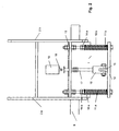
- a housing 1 is pivotably articulated on a stationary holder 2a and 2b.
- a drive shaft 3 which carries a bevel gear 4 at the end, is rotatably supported by roller bearings 5 and 6.
- the bevel gear 4 meshes with a conical ring gear 7, which is seated on an output shaft 8, which in turn is mounted in the housing 1 via roller bearings 9.
- the drive shaft 3 is, as indicated by the arrow a, seen from the outside, in Driven clockwise.
- the output shaft 8 accordingly rotates in the drawing seen from the left, counterclockwise (see arrow b).
- the Output shaft 8 becomes counterclockwise acting on the housing Reaction moment generated (arrow c).
- Fig. 2 shows the front view of the transmission as viewed from above results on the transmission of FIG. 1.
- an actuator can be seen, which serves to tilt the To counteract housing 1. This ensures that the limit from which the Transmission control begins by tilting the housing 1, can be determined.
- the actuating device here comprises 2 compression springs 10a and 10b, which are each held by a threaded rod 11a, b.
- the threaded rods 11a, b are screwed on the one hand to the projection of a base plate 12 of the housing and on the other hand to a connecting web 13 between the two flanges 2a and 2b of the stationary holder.
- the compression force of the springs 10a, b on the threaded rods 11a, b can be adjusted by means of adjusting screws 14a, b.
- the plunger 17 slidably protrudes through the connecting web 13 of the two flanges 2a, b of the stationary holder in order to actuate the limit switch 18 of a circuit 19 which is fastened to the holder 13 when it moves upward. This contact takes place depending on the setting of the compression springs 10 a, b. As soon as the reaction torque exceeds the counter torque determined by the set spring force when the output shaft 8 is braked, the plunger 17 moves upwards together with the housing 1 tilted upwards and comes into contact with the limit switch 18 of the circuit 19.
- the circuit 19, which can be designed as an electrical circuit and / or as a hydraulic and / or as a magnetic circuit, controls either the rotational speed of the drive shaft 3, amplifying it, or the braking force acting on the output shaft, reducing it.
- Fig. 3 shows a side view of the connection of the drive shaft 3 with that in the housing located gear and the actuator from the side. This clearly shows that the compression springs 10a, b on the one hand on the projection of the bottom plate 12 of the housing 1 and on the other hand are connected to the flanges 2 a, b of the stationary holder.
- the Limit switch 18 sits on the connecting web 13.
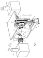
- 4 and 5 is a transmission gear 30 with the two gears 30a and 30b shown, which can be actuated via a lever linkage 31, 32.
- the lever arm 31 is on one of two interconnected projections 33, 34 attached to the Base plate 12 of the housing sit.
- Each tilting movement of the housing 1 is therefore articulated via the lever arm 31 connected to this lever arm 32 and transmitted from this to the gear 30a, which meshes with the smaller gear 30 b.
- the oil supply through the outlet 36 controlled to the actuating cylinder for the drive shaft 3.
- the others Outlet ports 37 and 38 are with the oil pump (not shown) or a tank (not shown) connected.
- the toggle spindle 39 is, as in Connection in Fig. 2 explained, slidably mounted in a fork piece 16, so that it does not hinder the tilting movement of the housing 1.
- FIG. 6 shows the side view of a manure spreader.
- the manure On its bottom surface 21 is the manure, which by means of a slide 22, see Fig. 7, to the right, direction Spreading disc rollers is pushed.
- a slide 22 At the front of the gritter 20 are two counter-rotating spreader plate rollers 23 a, b.
- the spreading plate rollers 23 a, b are connected to the output shaft 8.
- the power transmission from the tractor to Transmission control takes place via an articulated shaft 24, which is connected to the drive shaft 3 connected is.
- the Output shaft 8 is braked, a reaction moment arises, which in accordance with the setting of the spring forces 10 a, b in the adjusting device, the housing 1 upwards tilts (Fig. 3, counterclockwise).
- the stamp 17 then contacts the limit switch 18.
- the switching sensor system 19 causes an increase in the driving force PTO shaft 24 on the drive shaft 3 of the transmission and via its output shaft 8 an increased speed of rotation of the spreading plate rollers 23a, b, through which the Dung blockage within the spreading disc rollers is removed.
- the sensor technology can also be applied to the motor with constant driving force Act movement of the slider 22 to the braking force acting on the output shaft to reduce.
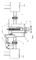
- FIGS. 8 and 9 show the use of the transmission gear 4 and 5 in the manure spreader 20 shown in FIGS. 6 and 7.
- the Output shaft 3 of the gearbox is connected via couplings 40 a, b with the spreading plate rollers 23 a, 23 b connected.
- the drive shaft 3 leads to the actuating cylinder for the sliding floor 22nd
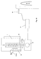
- the counter torque can also be made depending on the driving speed of the spreader 22 continuously change.
- the driving speed provides this of the spreader via a wheel sensor 50 data for control 51 a Drive motor 52, which is connected to the toggle spindle 39, and its setting in Controls depending on the driving speed.
Landscapes
- Engineering & Computer Science (AREA)
- General Engineering & Computer Science (AREA)
- Mechanical Engineering (AREA)
- Fertilizing (AREA)
- Fertilizers (AREA)
- Arrangement And Driving Of Transmission Devices (AREA)
- Agricultural Machines (AREA)
- Body Structure For Vehicles (AREA)
Abstract
Description
- Fig. 1
- eine Draufsicht auf das aufgebrochene Getriebegehäuse,
- Fig. 2
- eine Vorderansicht des Getriebegehäuses mit Stellvorrichtung,
- Fig. 3
- eine Seitenansicht des Getriebes,
- Fig. 4
- eine perspektivische Darstellung des mit dem Gehäuse der Getriebesteuerung verbundenen Übersetzungsgetriebes,
- Fig. 5
- eine perspektivische Darstellung eines Ausschnitts aus Fig. 4,
- Fig. 6
- eine Seitenansicht eines Miststreuwagens,
- Fig. 7
- eine Draufsicht auf den Miststreuwagen mit dem Streuwerk,
- Fig. 8
- eine perspektivische Darstellung des Getriebegehäuses mit Übersetzungsgetriebe und Durchflussregelventil im Verbindung mit den schematisch angedeuteten Streutellerwalzen,
- Fig. 9
- eine Vorderansicht, teils in aufgebrochener Form der Fig. 8 und
- Fig. 10
- eine schematische Darstellung der Steuerung für die Einstellung der Federkraft.
In dem Gehäuse 1 ist eine Antriebswelle 3, die stirnseitig ein Kegelrad 4 trägt, über Rollenlager 5 und 6 drehbar gelagert. Das Kegelrad 4 kämmt mit einem kegelförmigen Tellerrad 7, welches auf einer Abtriebswelle 8 sitzt, die ihrerseits über Rollenlager 9 im Gehäuse 1 gelagert ist.
Mittels Stellschrauben 14 a, b lässt sich die Druckkraft der Federn 10a, b auf den Gewindestangen 11 a, b einstellen. Zwischen den Gewindestangen 11 a, b befindet sich auf dem Vorsprung der Bodenplatte 12 ein Vierkant mit Bohrung 15, der über ein Gabelstück 16 mit einem Stempel 17 verbunden ist. Der Stempel 17 ragt verschiebbar durch den Verbindungssteg 13 der beiden Flansche 2a, b der stationären Halterung hindurch, um bei seiner Aufwärtsbewegung den Endschalter 18 eines Schaltkreises 19, der an der Halterung 13 befestigt ist, zu betätigen. Dieser Kontakt erfolgt abhängig von der Einstellung der Druckfedern 10 a, b. Sobald bei Abbremsung der Abtriebswelle 8 das Reaktionsmoment das durch die eingestellte Federkraft bestimmte Gegenmoment übersteigt, bewegt sich der Stempel 17 zusammen mit dem nach oben gekippten Gehäuse 1 nach oben und kommt mit dem Endschalter 18 des Schaltkreises 19 in Kontakt. Der Schaltkreis 19, welcher als elektrischer Schaltkreis und/oder als hydraulischer und/oder als magnetischer Schaltkreis ausgebildet sein kann, steuert entweder die Umdrehungsgeschwindigkeit der Antriebswelle 3, diese verstärkend, oder die auf die Abtriebswelle wirkende Bremskraft, diese verringernd.
Claims (16)
- In einem Gehäuse untergebrachtes Getriebe mit einer Antriebs- und einer Abtriebswelle, die in dem Gehäuse gelagert sind, dadurch gekennzeichnet, dass das Gehäuse (1) in einer stationären Halterung (2a, 2b) aufgehängt ist und dass das bei Veränderung des Drehmomentes einer Welle (3,8) entstehende Reaktionsmoment des Gehäuses als Steuergröße für eine Regelung dient.
- Getriebe nach Anspruch 1, dadurch gekennzeichnet, dass das Getriebe ein mit der Antriebswelle (3) verbundenes Antriebskegelrad (4) und ein mit diesem kämmendes kegelförmiges Tellerrad (7) umfasst, welches mit der Antriebswelle (8) verbunden ist, dass beide Wellen in dem Gehäuse (1) gelagert sind, welches seinerseits kippbar in der stationären Halterung (2a,2b) aufgehängt ist.
- Getriebe nach Anspruch 1 oder 2, dadurch gekennzeichnet, dass in der stationären Halterung (2a,2b) eine Sensorik (19) untergebracht ist.
- Getriebe nach einem der vorhergehenden Ansprüche, dadurch gekennzeichnet, dass das bei Abbremsung der mit dem Tellerrad (7) verbundenen Abtriebswelle (8) entstehende Reaktionsmoment zu einer Kippbewegung des Gehäuses (1) führt, durch die die Sensorik (19) betätigt wird, welche ihrerseits eine Änderung der Umdrehungszahl der das Kegelrad (4) stirnseitig tragenden Antriebswelle (3) oder eine Verringerung der Bremskraft bei Konstanthaltung der Umdrehungszahl der Antriebswelle bewirkt.
- Getriebe nach einem der vorhergehenden Ansprüche, dadurch gekennzeichnet, dass eine Stellvorrichtung (10 a,b, 11 a,b, 14 a,b ,39) zwischen der stationären Halterung (2a,b) und dem Gehäuse (1) angeordnet ist, die eine Gegenkraft gegen die Kippbewegung des Gehäuses (1) ausübt, um den Einsatzzeitpunkt der Sensorik zu bestimmen.
- Getriebe nach einem der vorhergehenden Ansprüche, dadurch gekennzeichnet, dass die Gegenkraft der Stellvorrichtung veränderbar ist.
- Getriebe nach einem der vorhergehenden Ansprüche, dadurch gekennzeichnet, dass die Stellvorrichtung durch eine oder mehrere Druckfedern (10 a,b) gebildet ist, deren Federkraft mittels Stellschrauben (14 a,b) bestimmbar ist.
- Getriebe nach einem der vorhergehenden Ansprüche, dadurch gekennzeichnet, dass die Stellvorrichtung einen am Gehäuse (1) angeordneten Betätigungsstift (17) umfasst, der bei Verschwenkung des Gehäuses (1) einen Endschalter (18) der Sensorik (19) betätigt.
- Getriebe nach einem der vorhergehenden Ansprüche, dadurch gekennzeichnet, dass die Sensorik (19) ein Übersetzungsgetriebe (30 a,b) umfasst, welches durch ein Hebelgestänge (31, 32) betätigt wird, dass seinerseits die Kippbewegungen des Gehäuses auf das Übersetzungsgetriebe überträgt.
- Getriebe nach Anspruch 9, dadurch gekennzeichnet, dass das Übersetzungsgetrisebe als ein Zahnradgetriebe (30a, 30b) ausgebildet ist.
- Getriebe nach Anspruch 9 oder 10, dadurch gekennzeichnet, dass das Übersetzungsgetriebe ein Durchflussregelventil (35) betätigt, welches durch Veränderung des Ölflusses in, über mit der Antriebs- und/oder Abtriebswelle verbundenen Arbeitszylindern ,deren Rotationsgeschwindigkeit steuert.
- Miststreuwagen, umfassend eine Beladefläche für das Streumedium, die an ihrer Stirnfläche vertikal angeordnete drehbare Streutellerwalzen und einen längs der Beladefläche bewegbaren Schieber aufweist, dadurch gekennzeichnet, dass ein von der Zugmaschine aus betätigbarer Antriebszylinder (24) gelenkig mit der Antriebswelle (3) des Getriebes nach einem der Ansprüche 1 bis 11 und mit dieser wiederum mit dem Getriebegehäuse (1) verbunden ist, welches über die Abtriebswelle (8) die Drehbewegung der Streutellerwalzen (23 a,b) steuert.
- Miststreuwagen, umfassend eine Beladefläche für das Streumedium, die an ihrer Stirnfläche vertikal angeordnete drehbare Streutellerwalzen und einen längs der Beladefläche bewegbaren Schieber aufweist, dadurch gekennzeichnet, dass die Lage des Schiebers (22) relativ zur Bodenfläche des Wagens über einen Schubzylinder steuerbar ist, wobei die dem Schubzylinder zugeführte Ölmenge durch ein Durchflussregelventil (35) bestimmt wird, welches seinerseits durch ein Übersetzungsgetriebe (30 a, b) gesteuert wird, dem ,über ein Hebelgestänge (31, 32) ,die ,durch das bei Änderung der auf die Abtriebswelle (8) einwirkenden Kraft entstehende Reaktionsmoment verursachte Kippbewegung des Getriebegehäuses (1) übertragen wird.
- Miststreuwagen nach einem der Ansprüche 12 und 13, dadurch gekennzeichnet, dass die Federkräfte für die Bestimmung des Gegenmomentes gegen die Kippbewegung des Getriebegehäuses kontinuierlich veränderbar sind.
- Miststreuwagen nach Anspruch 14, dadurch gekennzeichnet, dass die Einstellung der Federkräfte über eine Einstellspindel (399 erfolgt, die von einem Stellmotor (51) betätigt wird, der seinerseits abhängig von der Fahrgeschwindigkeit des Mistwagens ist.
- Miststreuwagen nach Anspruch 15, dadurch gekennzeichnet, dass die Fahrgeschwindigkeit des Mistwagens über einen Radsensor (50) erfasst wird, dessen Daten über eine Steuerung den Stellmotor (51) für die Einstellspindel (39) betätigt.
Applications Claiming Priority (2)
| Application Number | Priority Date | Filing Date | Title |
|---|---|---|---|
| DE20300970U | 2003-01-21 | ||
| DE20300970U DE20300970U1 (de) | 2003-01-21 | 2003-01-21 | Getriebesteuerung |
Publications (2)
| Publication Number | Publication Date |
|---|---|
| EP1441153A1 true EP1441153A1 (de) | 2004-07-28 |
| EP1441153B1 EP1441153B1 (de) | 2007-10-31 |
Family
ID=7979320
Family Applications (1)
| Application Number | Title | Priority Date | Filing Date |
|---|---|---|---|
| EP04000917A Expired - Lifetime EP1441153B1 (de) | 2003-01-21 | 2004-01-17 | Miststreuwagen mit einer Getriebesteuerung |
Country Status (5)
| Country | Link |
|---|---|
| EP (1) | EP1441153B1 (de) |
| AT (1) | ATE377166T1 (de) |
| DE (2) | DE20300970U1 (de) |
| DK (1) | DK1441153T3 (de) |
| ES (1) | ES2294377T3 (de) |
Citations (5)
| Publication number | Priority date | Publication date | Assignee | Title |
|---|---|---|---|---|
| FR766828A (fr) * | 1933-01-11 | 1934-07-04 | Perfectionnements apportés aux dispositifs de commande des transmissions à vitessevariable, notamment à celles que comportent les véhicules automobiles | |
| DE871670C (de) * | 1940-03-30 | 1953-03-26 | E H Carl F W Borgward Dr Ing | Selbsttaetige Schaltvorrichtung fuer das Schaltgetriebe von Kraftfahrzeugen |
| GB760213A (en) * | 1950-12-23 | 1956-10-31 | Atkinsons Agricultural Appl | Load carrying vehicle with load ejecting means |
| GB788850A (en) * | 1956-10-18 | 1958-01-08 | Josef Roiser | Improvements in or relating to mobile manure spreaders |
| US5408887A (en) * | 1992-09-19 | 1995-04-25 | Gkn Walterscheid Gmbh | Drive unit for driving agricultural implements or for effecting the drive in agricultural implements |
Family Cites Families (2)
| Publication number | Priority date | Publication date | Assignee | Title |
|---|---|---|---|---|
| DE4040652C2 (de) | 1990-12-19 | 2000-06-21 | Amazonen Werke Dreyer H | Landwirtschaftliche Maschine |
| DE4201300A1 (de) | 1992-01-20 | 1993-07-22 | Mengele & Soehne Masch Karl | Verfahren und vorrichtung zur steuerung der ausbringmenge |
-
2003
- 2003-01-21 DE DE20300970U patent/DE20300970U1/de not_active Expired - Lifetime
-
2004
- 2004-01-17 EP EP04000917A patent/EP1441153B1/de not_active Expired - Lifetime
- 2004-01-17 DE DE502004005344T patent/DE502004005344D1/de not_active Expired - Lifetime
- 2004-01-17 AT AT04000917T patent/ATE377166T1/de active
- 2004-01-17 DK DK04000917T patent/DK1441153T3/da active
- 2004-01-17 ES ES04000917T patent/ES2294377T3/es not_active Expired - Lifetime
Patent Citations (5)
| Publication number | Priority date | Publication date | Assignee | Title |
|---|---|---|---|---|
| FR766828A (fr) * | 1933-01-11 | 1934-07-04 | Perfectionnements apportés aux dispositifs de commande des transmissions à vitessevariable, notamment à celles que comportent les véhicules automobiles | |
| DE871670C (de) * | 1940-03-30 | 1953-03-26 | E H Carl F W Borgward Dr Ing | Selbsttaetige Schaltvorrichtung fuer das Schaltgetriebe von Kraftfahrzeugen |
| GB760213A (en) * | 1950-12-23 | 1956-10-31 | Atkinsons Agricultural Appl | Load carrying vehicle with load ejecting means |
| GB788850A (en) * | 1956-10-18 | 1958-01-08 | Josef Roiser | Improvements in or relating to mobile manure spreaders |
| US5408887A (en) * | 1992-09-19 | 1995-04-25 | Gkn Walterscheid Gmbh | Drive unit for driving agricultural implements or for effecting the drive in agricultural implements |
Also Published As
| Publication number | Publication date |
|---|---|
| ATE377166T1 (de) | 2007-11-15 |
| DE502004005344D1 (de) | 2007-12-13 |
| EP1441153B1 (de) | 2007-10-31 |
| DK1441153T3 (da) | 2008-03-17 |
| DE20300970U1 (de) | 2003-05-28 |
| ES2294377T3 (es) | 2008-04-01 |
Similar Documents
| Publication | Publication Date | Title |
|---|---|---|
| EP0268555B1 (de) | Operationstisch mit einer um die Längs- und Querachse kippbaren Patientenauflage | |
| DE3431000C2 (de) | Vorrichtung zum Einstellen eines Lagebestimmungelementes für den Hub einer Biegepresse | |
| DE3742569A1 (de) | Hydromechanische antriebsuebertragungsvorrichtung, wie kupplung, getriebe oder dgl. | |
| EP0826501B2 (de) | Vorrichtung zum Einstellen einer Farbwerks- bzw. Feuchtwerkswalze einer Druckmaschine | |
| DE2533931A1 (de) | Vorrichtung zum ausraeumen von schuettgut u.dgl. mittels eines bunkerentleerungswagens | |
| DE2749079C2 (de) | Hydraulische Antriebsvorrichtung für den Stößel einer Zahnradstoßmaschine od.dgl. Werkzeugmaschine | |
| DE3238630A1 (de) | Maschine zum zerkleinern von gut, insbesondere von keramischem oder aehnlichem mahlgut | |
| DE3545858C1 (de) | Servosteuerung,insbesondere Servolenkung fuer Kraftfahrzeuge | |
| EP1441153B1 (de) | Miststreuwagen mit einer Getriebesteuerung | |
| DE202004000655U1 (de) | Getriebesteuerung | |
| DE2744698C2 (de) | Refiner zur Aufbereitung von Papierstoff | |
| DE10316142A1 (de) | Antriebseinheit für einen Granulator und Granulator mit einer solchen Antriebseinheit | |
| DE4020776A1 (de) | Vorrichtung zum antrieb eines werkzeuges fuer eine axiale hin- und herbewegung des werkzeuges | |
| DD275361A3 (de) | Fleischwolf | |
| DE1554810B1 (de) | Spritzgiessmaschine | |
| WO2022263185A1 (de) | Kontaktwalze für eine wickeleinrichtung | |
| DE102010037935B4 (de) | Schleuderdüngerstreuer | |
| DE102008054016B4 (de) | Vorrichtung zum Verbinden von thermoplastischen Materialbahnen mit einer oberen, eine Anpresskraft ausübenden Druckrolle und einem Heizelement | |
| EP0136467B1 (de) | Lagervorrichtung für einen auf- und ablaufenden Wickel | |
| DE178479C (de) | ||
| DE4445151C2 (de) | Rüttler | |
| DE102007016231B4 (de) | Verfahren und Vorrichtung zum Vorspannen eines Messerrotors einer Schneidvorrichtung | |
| DE3534341C2 (de) | ||
| DE142898C (de) | ||
| DE2652937A1 (de) | Friktionsspindelpresse |
Legal Events
| Date | Code | Title | Description |
|---|---|---|---|
| PUAI | Public reference made under article 153(3) epc to a published international application that has entered the european phase |
Free format text: ORIGINAL CODE: 0009012 |
|
| AK | Designated contracting states |
Kind code of ref document: A1 Designated state(s): AT BE BG CH CY CZ DE DK EE ES FI FR GB GR HU IE IT LI LU MC NL PT RO SE SI SK TR |
|
| AX | Request for extension of the european patent |
Extension state: AL LT LV MK |
|
| 17P | Request for examination filed |
Effective date: 20050127 |
|
| AKX | Designation fees paid |
Designated state(s): AT BE BG CH CY CZ DE DK EE ES FI FR GB GR HU IE IT LI LU MC NL PT RO SE SI SK TR |
|
| 17Q | First examination report despatched |
Effective date: 20060913 |
|
| GRAP | Despatch of communication of intention to grant a patent |
Free format text: ORIGINAL CODE: EPIDOSNIGR1 |
|
| RTI1 | Title (correction) |
Free format text: MANURE SPREADER WITH A TRANSMISSION CONTROL DEVICE |
|
| GRAS | Grant fee paid |
Free format text: ORIGINAL CODE: EPIDOSNIGR3 |
|
| GRAA | (expected) grant |
Free format text: ORIGINAL CODE: 0009210 |
|
| AK | Designated contracting states |
Kind code of ref document: B1 Designated state(s): AT BE BG CH CY CZ DE DK EE ES FI FR GB GR HU IE IT LI LU MC NL PT RO SE SI SK TR |
|
| REG | Reference to a national code |
Ref country code: GB Ref legal event code: FG4D Free format text: NOT ENGLISH |
|
| REG | Reference to a national code |
Ref country code: IE Ref legal event code: FG4D Free format text: LANGUAGE OF EP DOCUMENT: GERMAN |
|
| REG | Reference to a national code |
Ref country code: CH Ref legal event code: EP |
|
| REF | Corresponds to: |
Ref document number: 502004005344 Country of ref document: DE Date of ref document: 20071213 Kind code of ref document: P |
|
| REG | Reference to a national code |
Ref country code: CH Ref legal event code: NV Representative=s name: RIEDERER HASLER & PARTNER PATENTANWAELTE AG |
|
| REG | Reference to a national code |
Ref country code: DK Ref legal event code: T3 |
|
| NLV1 | Nl: lapsed or annulled due to failure to fulfill the requirements of art. 29p and 29m of the patents act | ||
| REG | Reference to a national code |
Ref country code: ES Ref legal event code: FG2A Ref document number: 2294377 Country of ref document: ES Kind code of ref document: T3 |
|
| ET | Fr: translation filed | ||
| PG25 | Lapsed in a contracting state [announced via postgrant information from national office to epo] |
Ref country code: NL Free format text: LAPSE BECAUSE OF FAILURE TO SUBMIT A TRANSLATION OF THE DESCRIPTION OR TO PAY THE FEE WITHIN THE PRESCRIBED TIME-LIMIT Effective date: 20071031 Ref country code: SE Free format text: LAPSE BECAUSE OF FAILURE TO SUBMIT A TRANSLATION OF THE DESCRIPTION OR TO PAY THE FEE WITHIN THE PRESCRIBED TIME-LIMIT Effective date: 20080131 |
|
| GBV | Gb: ep patent (uk) treated as always having been void in accordance with gb section 77(7)/1977 [no translation filed] | ||
| PG25 | Lapsed in a contracting state [announced via postgrant information from national office to epo] |
Ref country code: PT Free format text: LAPSE BECAUSE OF FAILURE TO SUBMIT A TRANSLATION OF THE DESCRIPTION OR TO PAY THE FEE WITHIN THE PRESCRIBED TIME-LIMIT Effective date: 20080331 Ref country code: SI Free format text: LAPSE BECAUSE OF FAILURE TO SUBMIT A TRANSLATION OF THE DESCRIPTION OR TO PAY THE FEE WITHIN THE PRESCRIBED TIME-LIMIT Effective date: 20071031 Ref country code: BG Free format text: LAPSE BECAUSE OF FAILURE TO SUBMIT A TRANSLATION OF THE DESCRIPTION OR TO PAY THE FEE WITHIN THE PRESCRIBED TIME-LIMIT Effective date: 20080131 |
|
| REG | Reference to a national code |
Ref country code: IE Ref legal event code: FD4D |
|
| BERE | Be: lapsed |
Owner name: FLIEGL, JOSEF Effective date: 20080131 |
|
| PG25 | Lapsed in a contracting state [announced via postgrant information from national office to epo] |
Ref country code: MC Free format text: LAPSE BECAUSE OF NON-PAYMENT OF DUE FEES Effective date: 20080131 Ref country code: SK Free format text: LAPSE BECAUSE OF FAILURE TO SUBMIT A TRANSLATION OF THE DESCRIPTION OR TO PAY THE FEE WITHIN THE PRESCRIBED TIME-LIMIT Effective date: 20071031 Ref country code: RO Free format text: LAPSE BECAUSE OF FAILURE TO SUBMIT A TRANSLATION OF THE DESCRIPTION OR TO PAY THE FEE WITHIN THE PRESCRIBED TIME-LIMIT Effective date: 20071031 |
|
| PLBE | No opposition filed within time limit |
Free format text: ORIGINAL CODE: 0009261 |
|
| STAA | Information on the status of an ep patent application or granted ep patent |
Free format text: STATUS: NO OPPOSITION FILED WITHIN TIME LIMIT |
|
| 26N | No opposition filed |
Effective date: 20080801 |
|
| PG25 | Lapsed in a contracting state [announced via postgrant information from national office to epo] |
Ref country code: IE Free format text: LAPSE BECAUSE OF FAILURE TO SUBMIT A TRANSLATION OF THE DESCRIPTION OR TO PAY THE FEE WITHIN THE PRESCRIBED TIME-LIMIT Effective date: 20071031 |
|
| PG25 | Lapsed in a contracting state [announced via postgrant information from national office to epo] |
Ref country code: GB Free format text: LAPSE BECAUSE OF FAILURE TO SUBMIT A TRANSLATION OF THE DESCRIPTION OR TO PAY THE FEE WITHIN THE PRESCRIBED TIME-LIMIT Effective date: 20071031 |
|
| PG25 | Lapsed in a contracting state [announced via postgrant information from national office to epo] |
Ref country code: GR Free format text: LAPSE BECAUSE OF FAILURE TO SUBMIT A TRANSLATION OF THE DESCRIPTION OR TO PAY THE FEE WITHIN THE PRESCRIBED TIME-LIMIT Effective date: 20080201 Ref country code: EE Free format text: LAPSE BECAUSE OF FAILURE TO SUBMIT A TRANSLATION OF THE DESCRIPTION OR TO PAY THE FEE WITHIN THE PRESCRIBED TIME-LIMIT Effective date: 20071031 |
|
| PG25 | Lapsed in a contracting state [announced via postgrant information from national office to epo] |
Ref country code: FI Free format text: LAPSE BECAUSE OF FAILURE TO SUBMIT A TRANSLATION OF THE DESCRIPTION OR TO PAY THE FEE WITHIN THE PRESCRIBED TIME-LIMIT Effective date: 20071031 Ref country code: BE Free format text: LAPSE BECAUSE OF NON-PAYMENT OF DUE FEES Effective date: 20080131 |
|
| PG25 | Lapsed in a contracting state [announced via postgrant information from national office to epo] |
Ref country code: CY Free format text: LAPSE BECAUSE OF FAILURE TO SUBMIT A TRANSLATION OF THE DESCRIPTION OR TO PAY THE FEE WITHIN THE PRESCRIBED TIME-LIMIT Effective date: 20071031 |
|
| PG25 | Lapsed in a contracting state [announced via postgrant information from national office to epo] |
Ref country code: LU Free format text: LAPSE BECAUSE OF NON-PAYMENT OF DUE FEES Effective date: 20080117 Ref country code: HU Free format text: LAPSE BECAUSE OF FAILURE TO SUBMIT A TRANSLATION OF THE DESCRIPTION OR TO PAY THE FEE WITHIN THE PRESCRIBED TIME-LIMIT Effective date: 20080501 |
|
| PG25 | Lapsed in a contracting state [announced via postgrant information from national office to epo] |
Ref country code: TR Free format text: LAPSE BECAUSE OF FAILURE TO SUBMIT A TRANSLATION OF THE DESCRIPTION OR TO PAY THE FEE WITHIN THE PRESCRIBED TIME-LIMIT Effective date: 20071031 |
|
| PG25 | Lapsed in a contracting state [announced via postgrant information from national office to epo] |
Ref country code: IT Free format text: LAPSE BECAUSE OF NON-PAYMENT OF DUE FEES Effective date: 20080131 |
|
| REG | Reference to a national code |
Ref country code: DE Ref legal event code: R082 Ref document number: 502004005344 Country of ref document: DE Representative=s name: TETZNER, MICHAEL, DIPL.-ING.-UNIV., DE |
|
| REG | Reference to a national code |
Ref country code: DE Ref legal event code: R081 Ref document number: 502004005344 Country of ref document: DE Owner name: FLIEGL, JOSEF, DE Free format text: FORMER OWNER: FLIEGL, JOSEF, 84513 TOEGING, DE Effective date: 20131112 Ref country code: DE Ref legal event code: R082 Ref document number: 502004005344 Country of ref document: DE Representative=s name: TETZNER, MICHAEL, DIPL.-ING.-UNIV., DE Effective date: 20131112 |
|
| REG | Reference to a national code |
Ref country code: FR Ref legal event code: PLFP Year of fee payment: 13 |
|
| REG | Reference to a national code |
Ref country code: FR Ref legal event code: PLFP Year of fee payment: 14 |
|
| REG | Reference to a national code |
Ref country code: FR Ref legal event code: PLFP Year of fee payment: 15 |
|
| PGFP | Annual fee paid to national office [announced via postgrant information from national office to epo] |
Ref country code: FR Payment date: 20230123 Year of fee payment: 20 Ref country code: ES Payment date: 20230216 Year of fee payment: 20 Ref country code: DK Payment date: 20230123 Year of fee payment: 20 Ref country code: CZ Payment date: 20230104 Year of fee payment: 20 Ref country code: CH Payment date: 20230130 Year of fee payment: 20 Ref country code: AT Payment date: 20230118 Year of fee payment: 20 |
|
| PGFP | Annual fee paid to national office [announced via postgrant information from national office to epo] |
Ref country code: DE Payment date: 20230119 Year of fee payment: 20 |
|
| REG | Reference to a national code |
Ref country code: DE Ref legal event code: R071 Ref document number: 502004005344 Country of ref document: DE |
|
| REG | Reference to a national code |
Ref country code: DK Ref legal event code: EUP Expiry date: 20240117 |
|
| REG | Reference to a national code |
Ref country code: ES Ref legal event code: FD2A Effective date: 20240126 |
|
| REG | Reference to a national code |
Ref country code: CH Ref legal event code: PL |
|
| REG | Reference to a national code |
Ref country code: AT Ref legal event code: MK07 Ref document number: 377166 Country of ref document: AT Kind code of ref document: T Effective date: 20240117 |
|
| PG25 | Lapsed in a contracting state [announced via postgrant information from national office to epo] |
Ref country code: ES Free format text: LAPSE BECAUSE OF EXPIRATION OF PROTECTION Effective date: 20240118 |
|
| PG25 | Lapsed in a contracting state [announced via postgrant information from national office to epo] |
Ref country code: ES Free format text: LAPSE BECAUSE OF EXPIRATION OF PROTECTION Effective date: 20240118 Ref country code: CZ Free format text: LAPSE BECAUSE OF EXPIRATION OF PROTECTION Effective date: 20240117 |