EP1440436B1 - Gleiter für eine optische datenschreib-/ lesevorrichtung und vorrichtung mit einem solchen gleiter - Google Patents
Gleiter für eine optische datenschreib-/ lesevorrichtung und vorrichtung mit einem solchen gleiter Download PDFInfo
- Publication number
- EP1440436B1 EP1440436B1 EP02801458A EP02801458A EP1440436B1 EP 1440436 B1 EP1440436 B1 EP 1440436B1 EP 02801458 A EP02801458 A EP 02801458A EP 02801458 A EP02801458 A EP 02801458A EP 1440436 B1 EP1440436 B1 EP 1440436B1
- Authority
- EP
- European Patent Office
- Prior art keywords
- slider
- disk
- legs
- bridge
- island portion
- Prior art date
- Legal status (The legal status is an assumption and is not a legal conclusion. Google has not performed a legal analysis and makes no representation as to the accuracy of the status listed.)
- Expired - Lifetime
Links
- 230000003287 optical effect Effects 0.000 title claims abstract description 34
- 239000000725 suspension Substances 0.000 claims description 13
- 238000003860 storage Methods 0.000 description 5
- 238000013459 approach Methods 0.000 description 4
- 230000007423 decrease Effects 0.000 description 2
- 238000002474 experimental method Methods 0.000 description 2
- 239000000463 material Substances 0.000 description 2
- 238000005259 measurement Methods 0.000 description 2
- 238000000034 method Methods 0.000 description 2
- 239000012780 transparent material Substances 0.000 description 2
- 230000002301 combined effect Effects 0.000 description 1
- 238000013500 data storage Methods 0.000 description 1
- 230000003247 decreasing effect Effects 0.000 description 1
- 238000013461 design Methods 0.000 description 1
- 238000006073 displacement reaction Methods 0.000 description 1
- 238000009826 distribution Methods 0.000 description 1
- 230000000694 effects Effects 0.000 description 1
- 238000005530 etching Methods 0.000 description 1
- 239000011521 glass Substances 0.000 description 1
- 238000004519 manufacturing process Methods 0.000 description 1
- 238000012986 modification Methods 0.000 description 1
- 230000004048 modification Effects 0.000 description 1
- 239000006070 nanosuspension Substances 0.000 description 1
- 230000000704 physical effect Effects 0.000 description 1
- 230000010287 polarization Effects 0.000 description 1
- 230000001681 protective effect Effects 0.000 description 1
- 239000007787 solid Substances 0.000 description 1
- 238000012546 transfer Methods 0.000 description 1
- 238000001039 wet etching Methods 0.000 description 1
Images

Classifications
-
- G—PHYSICS
- G11—INFORMATION STORAGE
- G11B—INFORMATION STORAGE BASED ON RELATIVE MOVEMENT BETWEEN RECORD CARRIER AND TRANSDUCER
- G11B21/00—Head arrangements not specific to the method of recording or reproducing
- G11B21/16—Supporting the heads; Supporting the sockets for plug-in heads
- G11B21/20—Supporting the heads; Supporting the sockets for plug-in heads while the head is in operative position but stationary or permitting minor movements to follow irregularities in surface of record carrier
- G11B21/21—Supporting the heads; Supporting the sockets for plug-in heads while the head is in operative position but stationary or permitting minor movements to follow irregularities in surface of record carrier with provision for maintaining desired spacing of head from record carrier, e.g. fluid-dynamic spacing, slider
-
- G—PHYSICS
- G11—INFORMATION STORAGE
- G11B—INFORMATION STORAGE BASED ON RELATIVE MOVEMENT BETWEEN RECORD CARRIER AND TRANSDUCER
- G11B7/00—Recording or reproducing by optical means, e.g. recording using a thermal beam of optical radiation by modifying optical properties or the physical structure, reproducing using an optical beam at lower power by sensing optical properties; Record carriers therefor
- G11B7/12—Heads, e.g. forming of the optical beam spot or modulation of the optical beam
- G11B7/122—Flying-type heads, e.g. analogous to Winchester type in magnetic recording
-
- B—PERFORMING OPERATIONS; TRANSPORTING
- B82—NANOTECHNOLOGY
- B82Y—SPECIFIC USES OR APPLICATIONS OF NANOSTRUCTURES; MEASUREMENT OR ANALYSIS OF NANOSTRUCTURES; MANUFACTURE OR TREATMENT OF NANOSTRUCTURES
- B82Y10/00—Nanotechnology for information processing, storage or transmission, e.g. quantum computing or single electron logic
Definitions
- the present invention relates in general to the field of writing data into a rotatable storage disk and reading data from such a rotatable storage disk.
- a storage disk may be a magnetic disk, an optical disk, a magneto-optical disk, etc.
- the present invention will be useful in writing/reading apparatuses based on optical means, including a laser beam, for the writing and reading action; therefore, the present invention will hereinafter be specifically explained with respect to such optical systems.
- the scope of the present invention is not restricted to such optical systems, and is equally applicable to a magnetic system.
- an optical storage/retrieval system comprises a rotatable disk and an optical head for scanning the surface of the disk.
- a laser beam is focused on the surface of the disk, and the disk is rotated with respect to the optical disk, such that the focused laser beam follows a circular track on the disk surface.
- the optical head is moved in a radial direction with respect to the disk.
- Data is stored on the disk by varying the beam intensity in a suitable manner, such that physical properties of the disk are modified.
- Data is read from the disk by sensing the intensity of a reflected beam. Since such data storage/retrieval systems using optical means are commonly known in general, they will not be explained here in more detail.
- the optical head comprises an optical lens mounted at an arm, which arm is positioned relatively to the disk by means of a suspension.
- the present invention relates to a specific type of optical head whose vertical positioning is based on the presence of an air cushion between the optical head and the disk surface.
- Such an optical head is also referred to as slider.
- a slider has a slider face directed towards the surface of the disk, which face is also referred to as air bearing surface.
- the distance between the air bearing slider surface and the disk surface is very small, typically of the order of 1 ⁇ m.
- a holder exerts a bias force on the slider, urging the slider towards the disk surface.
- air is sucked into the narrow gap between the air bearing slider surface and the disk surface, developing an air cushion with increased pressure, exerting a force on the slider directed away from the disk surface; this force will also be referred to as lift.
- the lift generated by the air cushion balances the bias force exerted by the holder, so that the distance between the air bearing slider surface and the disk surface remains constant. This distance is also referred to as flying height.
- a commonly known problem in this respect is that the flying height tends to depend on the velocity of the disk surface with respect to the air bearing slider surface, because the amount of air sucked into said gap depends on said velocity. Since it is desirable that the flying height should be as constant as possible as was noted above, countermeasures are necessary.
- One approach is to drive a storage and retrieval apparatus in such a way that the linear velocity of the disk with respect to the slider is kept constant. This, however, means that the angular velocity or rotation speed of the disk needs to be adapted to the radial position of the slider. Also, it is preferred to operate a disk drive at a constant angular velocity, because in such a mode the access times can be smaller than in a constant linear velocity (operational) mode.
- the lift at the outer diameter of the disk will always be greater than the lift at the inner diameter. This results in an increased flying height of the outer diameter as compared with the flying height at the inner diameter.
- EP-A-1,001,423 proposes to adjust the skew angle by moving the slider along a transfer path which does not correspond to a radial path.
- Skew introduces another problem, namely polarization rotation with respect to the grooves, which is disadvantageous for the tracking method and involves a decrease in the spot quality.
- the configuration disclosed by said publication is very complicated and difficult to manufacture. Furthermore, as demonstrated by Fig. 5 of said publication, the configuration disclosed by said publication is only capable of reducing the flying height at the outer diameter of the disk but is not capable of maintaining the flying height substantially over the entire disk.
- the slider has a pitch pivot axis substantially coinciding with the focal point of the optical lens.
- the invention further relates to an optical data writing and/or reading apparatus as defined in claim 10 or 11.
- Fig. 1 schematically shows part of a disk drive in plan view, generally indicated with the reference numeral 1.
- the disk drive apparatus 1 will comprise a housing, which is not shown for the sake of simplicity, and means for receiving a rotatable disk 2, which by way of an example is an optical disk.
- the disk drive apparatus 1 further comprises scan means 10 for scanning the surface of the disk 2 in order to write data onto the disk 2 or to read data from the disk 2.
- Such scan means 10 comprise a scan head 11, positioning means 20 for positioning the scan head 11 with respect to the disk, and moving means 30 for moving the scan head 11 with respect to the disk surface along circular tracks.
- the moving means 30 comprise disk rotating means 31 for rotating the disk 2, as indicated by the arrows R. Since means for receiving and rotating a disk in a disk drive apparatus are commonly known, this will not be explained in more detail.
- the positioning means 20 comprise an arm 21 which holds the scan head 11 above the surface 3 of the disk 2, as will be explained later in more detail.
- the disk has a center of rotation C R defined by the rotating means 31.
- the scan head 11 defines a scan position P S on the surface 3 of the disk 2.
- a radial line connecting the center of rotation C R with the scan position P S is referenced at L.
- the arm 21 has a central axis which preferably is directed perpendicular to said radial line L.
- the moving means 30 comprise arm displacing means 32 for displacing the arm 21 with the scan head 11 in a direction parallel to said radial line L, as indicated by arrows D. Since means for displacing a scan head 11 are commonly known, the arm displacement means 32 will not be described in more detail here.
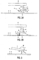
- Figs. 2A and 2B schematically show the free end of the arm 21 carrying the scan head 11 in side elevation.
- the scan head 11 comprises a scan head body 12 with a top surface 13 and a bottom surface 14, and is suspended from the free end of the arm 21 by resilient suspension means 22 capable of resiliently exerting a downwardly directed force on the scan head body 12.
- the suspension means 22 engages the scan head body 12 at a central location thereof, indicated as suspension location L S .
- the scan head body 12 is balanced with respect to the suspension means 22, such that, in a steady-state equilibrium, when the scan head 11 is positioned with its bottom surface 14 close to the surface 3 of the disk 2, the bottom surface 14 of the scan head 11 is substantially parallel to the disk surface 3, as shown in Fig. 2A .
- the disk rotates under the scan head 11 in a direction from left to right in the drawing, as illustrated by arrow R in Fig. 2B . Due to this rotation, air is sucked into the small gap 15 between the bottom surface 14 of the scan head 11 and the top surface 3 of the disk 2, as indicated by arrows A in Fig. 2B .
- the edge of the scan head 11 where the air flow A enters said gap 15 will be denoted the leading edge 16, whereas the opposite edge of the slider 11, where the air flow leaves said gap 15, will be denoted the trailing edge 17.
- This air flow causes a kind of air cushion under the bottom surface 14 of the scan head 11, with a rather complicated pressure distribution. Some parts of the bottom surface 14 of the scan head 11 feel an increased air pressure, while other parts feel a reduced pressure. Overall, the bottom surface 14 of the scan head 11 feels a force directed away from the disk 2. This upwardly directed air cushion force primarily obtains between the leading edge 16 and the suspension means 22, as indicated by arrow F U in Fig. 2B . This air cushion force F U tends to push the scan head 11 away from the moving disk 2.
- the slider 11 is kept in place by a downwardly directed force F D exerted by the resilient suspension means 22.
- the two forces F U and F D exerted on different locations of the slider 11, tend to tilt the slider 11 such that the leading edge 16 is lifted and the trailing edge 17 is lowered, as is clearly illustrated in Fig. 2B in an exaggerated manner.
- the centerline of the slider 11 now encloses an angle ⁇ with the surface 3 of the disk 2, indicated as pitch angle.
- the slider 11 carries a lens 40 which forms part of an optical system of the disk drive apparatus 1.
- the lens 40 receives a laser beam 41 which is directed substantially perpendicular to the surface 3 of the disk 2, and focuses the laser beam 41 on a focal spot 42.
- This focal spot 42 determines the scan position P S as indicated in Fig. 1 .
- the focal spot 42 may be at some distance below the bottom surface 14 of the slider 11, or rather close to the bottom surface 14 of the slider 11, such as in near-field technology. For accurate and high-density operation, it is desirable that the distance between the focal spot 42 and the disk surface 3 remains constant.
- the linear velocity of the disk 2 with respect to the slider 11 varies with varying distance between scan spot P S and rotational center C R . More particularly, when the slider 11 is close to the outer edge of the disk 2, the linear velocity of the disk 2 is greater, and hence the amount of air A sucked into the gap 15 is larger, as compared with the slider 11 being close to the center of rotation C R . With an increasing air flow A, the lift force F U increases, causing the distance between focal spot 42 and disk surface 3 to increase, which is undesirable.
- Fig. 3 shows, on an exaggerated scale, a slider 11 designed according to the present invention in side elevation.
- Fig. 3 clearly shows that the slider 11 has a lower surface 14 terminating close to the focal spot 42 at a certain distance from the trailing edge 17 of the slider 11.
- a back surface 19 meets the lower surface 14 at an angle greater than the pitch angle ⁇ , such that the meeting point 18 between back surface 19 and lower surface 14 is always the lowermost point of the slider 11.
- said angle is substantially equal to 90°, leading to a trailing balcony not shown in Fig. 3 .
- said angle is approximately 45°, and the back surface 19 tapers towards the trailing edge.
- the clearance between the focal spot 42 and the disk surface 3 will be denoted the flying height H F .
- Air flow A which is compressed under the tilted slider 11, expands after passing the lowermost slider point 18, causing the air pressure beyond the lowermost slider point 18 (in Fig. 3 : to the right of the lowermost slider point 18) to drop.
- the trailing portion of the slider 11 receives from the air A a reduced lift or even a downwardly directed suction force, indicated by arrow F S , which tends to increase the pitch angle ⁇ .
- the pitch angle ⁇ will increase due to the combined effect of lift force F U acting on a leading portion of the slider and suction force F S acting on a trailing portion of the slider.
- the bottom geometry of the slider 11 is designed such that tilting of the slider (i.e. increasing of pitch angle ⁇ ) takes place as a pivotal movement with respect to a horizontal pivot axis PA which is located in a vertical plane through the focal spot 42.
- tilting of the slider i.e. increasing of pitch angle ⁇
- ⁇ tilting of the slider
- the focal spot coincides with said pivot axis.
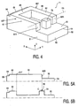
- Fig. 4 is a three-dimensional view of the bottom of a slider 11, placed upside down.
- a longitudinal direction will be denoted the X-direction
- a transverse direction will be denoted the Y-direction (X and Y being parallel to a disk surface in normal conditions).
- the slider 11 has a substantially rectangular slider body 50 and a substantially U-shaped raised portion 60.
- This raised portion 60 comprises two legs 61, 62 which are arranged alongside the side edges 51, 52 of the slider body 50, each leg 61, 62 having a front end 61F, 62F and a rear end 61R, 62R.
- the raised portion 60 further has a bridge 63 connecting the front ends 61F, 62F of said legs 61, 62, the bridge 63 being arranged alongside the front edge 53 of the slider body 50.
- the bridge 63 and the legs 61, 62 each have a substantially rectangular cross-section in this example.
- the slider 11 has a width (Y-dimension) of 2.5 mm, and the bridge 63 entirely spans this width.
- the bridge 63 has a width (X-dimension) of 0.8 mm.
- the slider 11 has a length (X-dimension) of 3.5 mm, but the legs 61, 62 are shorter.
- Each leg has a width (Y-dimension) of 0.48 mm, and a length (X-dimension) of 1.95 mm; thus, the rear end 61R, 62R of each leg 61, 62 is located at a distance of 0.75 mm from the trailing edge 54 of the slider.
- the height (Z-dimension) of the legs 61, 62 and the bridge 63 is approximately 7.1 ⁇ m.
- the slider 11 has a height (Z-dimension) of 250 ⁇ m.
- the bridge has at its front a stepped recess 64 over the entire length of the bridge 63.
- This stepped recess 64 has a depth (Z-dimension) of 1.0 ⁇ m and a width (X-dimension) of 0.15 mm.
- Fig. 5A is a longitudinal sectional view of the slider, taken on a leg 61
- Fig. 5B is a similar sectional view taken on the centerline of the slider.
- the remaining bottom face of the slider i.e. the bottom with the exception of the bridge 63 and legs 61, 62, will be referred to as recessed bottom surface 55.
- the exemplary slider has been manufactured starting from a solid block through etching away of portions thereof (using a wet etching technique) down to the desired depth, leaving the recessed bottom surface 55.
- the material was glass. In practice, other transparent materials will do. Alternatively, if one wishes to use non-transparent material, a transparent window for the optical components should be included.
- the slider further comprises a centrally located island portion 70, having a square configuration (in X- and Y-directions).
- the island portion 70 stands raised from the recessed bottom surface 55 and has a height equal to the height of the bridge 63 and legs 61, 62, such that the bottom surface of the island portion 70 lies in the same XY-plane as the bottom surface of the bridge 63 and the bottom surfaces of the legs 61, 62.
- the island portion 70 has a length (X-dimension) of 0.5 mm and a width (Y-dimension) of 0.5 mm.
- the center C of the island portion 70 is located on a line connecting the rear ends 61R, 62R of the legs 61, 62, at equal distances from said legs.
- a lens (not shown in Fig. 4 ) was mounted on the slider, having its optical axis coinciding with the center C of the island portion 70 and having a focal point 42 (see Fig. 2A ) coinciding with the face of the island portion.
- said focal point coincides with said center C.
- these Figures show a reference point PR, lying 0.22 mm behind the center C of the island portion 70.
- the slider 11 was suspended (U-shaped portion 60 down) from a suspension point located halfway between the leading edge 53 and the trailing edge 54.
- the suspension means used was a "nanosuspension 850 LSF", available as a standard component from the Hutchinson Technology Company of Hutchinson, MN, USA. This suspension has the following properties, specified in the range from 0.03 to 0.05 N:
- the suspended slider was placed above a disk, and the disk was rotated with varying speed.
- the flying height of the slider was measured at different positions.
- Fig. 6 shows the results of the measurements.
- the horizontal axis shows the linear speed of the disk surface 3 with respect to the slider 11.
- the vertical axis shows the flying height HF measured at the focal point C (indicated with line LF) and measured at said reference point PR (indicated with line LR). It is clearly visible that the flying height measured at the focal point is substantially constant (variation less than 2.5 %) over the entire range of disk speeds from 3 m/s to 6 m/s, corresponding to the normal speeds of a disk at its inner diameter and its outer diameter. Also, it can be seen that the flying height measured at the reference point PR decreases with increasing speed, thus indicating that the pivot axis PA is located at the focal point C.
Landscapes
- Engineering & Computer Science (AREA)
- Chemical & Material Sciences (AREA)
- Nanotechnology (AREA)
- Physics & Mathematics (AREA)
- Theoretical Computer Science (AREA)
- Crystallography & Structural Chemistry (AREA)
- Mathematical Physics (AREA)
- Optics & Photonics (AREA)
- Optical Head (AREA)
- Supporting Of Heads In Record-Carrier Devices (AREA)
- Facsimile Heads (AREA)
- Optical Recording Or Reproduction (AREA)
- Holo Graphy (AREA)
- Non-Silver Salt Photosensitive Materials And Non-Silver Salt Photography (AREA)
Claims (11)
- Gleiter (11) für ein optisches Daten-Schreib/Lesegerät (1), welcher Gleiter (11) eine optische Linse (40) trägt, die einen Brennpunkt (42) definiert;
wobei der Gleiter (11) mit federnden Aufhängemitteln versehen ist, die für eine Aufhängung an einem Arm (21) des genannten Gerätes eingerichtet sind, wobei der Gleiter (11) eine im Wesentlichen horizontale Schwenkachse (PA) hat, die im Wesentlichen in einer vertikalen Ebene durch den genannten Brennpunkt (42) gelegen ist. - Gleiter nach Anspruch 1, bei dem die Schwenkachse im Wesentlichen mit dem Brennpunkt zusammenfällt.
- Gleiter nach Anspruch 1 oder 2, mit:einem Gleiterkörper;einem im Wesentlichen U-förmigen erhöhten Abschnitt, der erhöht auf einer ausgesparten Bodenfläche steht, wobei der erhöhte Abschnitt zwei entlang Seitenkanten des Gleiterkörpers angeordnete Schenkel umfasst, wobei jeder Schenkel ein vorderes Ende und ein hinteres Ende hat, wobei der erhöhte Abschnitt weiterhin ein Brückenteil umfasst, das die vorderen Enden der genannten Schenkel verbindet, wobei das Brückenteil entlang einer vorderen Kante des Gleiterkörpers angeordnet ist;einem Inselabschnitt, der erhöht auf der ausgesparten Bodenfläche steht, wobei der Inselabschnitt eine Mitte hat, die auf einer die hinteren Enden der Schenkel verbindenden Linie liegt, in gleichem Abstand zu den genannten Schenkeln;bei dem der Brennpunkt im Wesentlichen mit der genannten Mitte des Inselabschnitts zusammenfällt.
- Gleiter nach Anspruch 3, bei dem der Inselabschnitt eine Höhe hat, die im Wesentlichen gleich der Höhe des Brückenteils und der Schenkel ist, so dass eine Unterseite des Inselabschnitts im Wesentlichen in der gleichen Ebene liegt wie eine Unterseite des Brückenteils und Unterseiten der Schenkel.
- Gleiter nach Anspruch 4, bei dem die genannte Mitte des Inselabschnitts im Wesentlichen mit der genannten Unterseite des Inselabschnitts zusammenfällt.
- Gleiter nach einem der Ansprüche 3 bis 5, bei dem das Brückenteil an seiner Stirnseite eine gestufte Aussparung hat.
- Gleiter nach Anspruch 6, bei dem die gestufte Aussparung sich über nahezu die gesamte Länge des Brückenteils erstreckt.
- Gleiter nach einem der Ansprüche 3 bis 7, bei dem das Brückenteil und die Schenkel jeweils einen nahezu rechteckigen Querschnitt haben.
- Gleiter nach einem der Ansprüche 3 bis 7, bei dem der Inselabschnitt eine nahezu quadratische Konfiguration/Form hat.
- Optisches Daten-Schreib/Lesegerät mit Abtastmitteln zum Abtasten der Oberfläche einer Disk, welche Abtastmittel einen Gleiter nach einem der Ansprüche 1 bis 9 umfassen.
- Optisches Daten-Schreib/Lesegerät nach Anspruch 10, wobei die Abtastmittel darüber hinaus umfassen:Diskdrehmittel zum Drehen einer Disk, wobei die Diskdrehmittel einen Drehungsmittelpunkt definieren;Positionierungsmittel zum Positionieren des Gleiters in Bezug auf die Disk, wobei die Positionierungsmittel einen Arm umfassen, an dem der Gleiter aufgehängt ist;Armverlagerungsmittel zum Verlagern des Arms mit dem Abtastkopf in einer Richtung parallel zu einer radialen Linie, die den Drehungsmittelpunkt mit dem Brennpunkt verbindet.
Priority Applications (1)
| Application Number | Priority Date | Filing Date | Title |
|---|---|---|---|
| EP02801458A EP1440436B1 (de) | 2001-10-18 | 2002-10-14 | Gleiter für eine optische datenschreib-/ lesevorrichtung und vorrichtung mit einem solchen gleiter |
Applications Claiming Priority (4)
| Application Number | Priority Date | Filing Date | Title |
|---|---|---|---|
| EP01203976 | 2001-10-18 | ||
| EP01203976 | 2001-10-18 | ||
| EP02801458A EP1440436B1 (de) | 2001-10-18 | 2002-10-14 | Gleiter für eine optische datenschreib-/ lesevorrichtung und vorrichtung mit einem solchen gleiter |
| PCT/IB2002/004234 WO2003034416A2 (en) | 2001-10-18 | 2002-10-14 | Slider for an optical data writing/reading apparatus, and apparatus comprising such a slider |
Publications (2)
| Publication Number | Publication Date |
|---|---|
| EP1440436A2 EP1440436A2 (de) | 2004-07-28 |
| EP1440436B1 true EP1440436B1 (de) | 2009-01-14 |
Family
ID=8181102
Family Applications (1)
| Application Number | Title | Priority Date | Filing Date |
|---|---|---|---|
| EP02801458A Expired - Lifetime EP1440436B1 (de) | 2001-10-18 | 2002-10-14 | Gleiter für eine optische datenschreib-/ lesevorrichtung und vorrichtung mit einem solchen gleiter |
Country Status (9)
| Country | Link |
|---|---|
| US (1) | US7516465B2 (de) |
| EP (1) | EP1440436B1 (de) |
| JP (1) | JP4145793B2 (de) |
| KR (1) | KR100926897B1 (de) |
| CN (1) | CN1322501C (de) |
| AT (1) | ATE421140T1 (de) |
| AU (1) | AU2002334335A1 (de) |
| DE (1) | DE60230899D1 (de) |
| WO (1) | WO2003034416A2 (de) |
Families Citing this family (1)
| Publication number | Priority date | Publication date | Assignee | Title |
|---|---|---|---|---|
| DE102004018049A1 (de) * | 2004-04-08 | 2005-10-27 | Deutsche Thomson-Brandt Gmbh | Slider mit konstanter Flughöhe |
Family Cites Families (16)
| Publication number | Priority date | Publication date | Assignee | Title |
|---|---|---|---|---|
| US5497359A (en) * | 1994-08-30 | 1996-03-05 | National Business Machines Corporation | Optical disk data storage system with radiation-transparent air-bearing slider |
| US6125008A (en) | 1996-04-15 | 2000-09-26 | Digital Papyrus Corporation | Flying head positioner having rotational fine positioning and adjustable actuator load |
| US5986850A (en) | 1997-06-16 | 1999-11-16 | Seagate Technology, Inc. | Positive pressure optical slider having wide center rail |
| US5970038A (en) * | 1997-06-20 | 1999-10-19 | Seagate Technology, Inc. | Reduction of mesa fly height modulation due to media asperities in magneto-optic drives |
| US5831797A (en) * | 1997-07-23 | 1998-11-03 | Seagate Technology, Inc. | Slider with mesa for optical disc data storage system |
| WO1999009547A1 (en) * | 1997-08-15 | 1999-02-25 | Seagate Technology, Inc. | Slider for disc storage system |
| US7092213B1 (en) * | 1998-09-25 | 2006-08-15 | Sae Magnetics (H.K.) Ltd. | Multiple level surface configuration for a sub-ambient pressure air bearing slider |
| US6137656A (en) * | 1998-10-26 | 2000-10-24 | Read-Rite Corporation | Air bearing slider |
| JP2000149476A (ja) | 1998-11-09 | 2000-05-30 | Fujitsu Ltd | 記録再生装置 |
| JP2000242955A (ja) * | 1999-02-17 | 2000-09-08 | Yamaha Corp | 光ヘッドおよびその製造方法 |
| JP2000285542A (ja) * | 1999-03-26 | 2000-10-13 | Yamaha Corp | 光磁気ヘッド |
| JP4485012B2 (ja) * | 1999-08-30 | 2010-06-16 | セイコーインスツル株式会社 | 光ヘッド |
| JP3366609B2 (ja) * | 1999-12-27 | 2003-01-14 | アルプス電気株式会社 | 磁気ヘッドおよび磁気記録装置 |
| JP3764846B2 (ja) * | 2000-08-30 | 2006-04-12 | アルプス電気株式会社 | 磁気ヘッドの製造方法 |
| JP4352607B2 (ja) * | 2000-12-07 | 2009-10-28 | パナソニック株式会社 | ヘッドスライダおよびこれを用いたディスク記録再生装置 |
| US6680821B2 (en) * | 2001-04-18 | 2004-01-20 | Hitachi Global Storage Technologies, The Netherlands B.V. | Slider air bearing surface having improved fly height profile characteristics |
-
2002
- 2002-10-14 WO PCT/IB2002/004234 patent/WO2003034416A2/en not_active Ceased
- 2002-10-14 EP EP02801458A patent/EP1440436B1/de not_active Expired - Lifetime
- 2002-10-14 DE DE60230899T patent/DE60230899D1/de not_active Expired - Lifetime
- 2002-10-14 KR KR1020047005647A patent/KR100926897B1/ko not_active Expired - Fee Related
- 2002-10-14 US US10/492,664 patent/US7516465B2/en not_active Expired - Fee Related
- 2002-10-14 AT AT02801458T patent/ATE421140T1/de not_active IP Right Cessation
- 2002-10-14 JP JP2003537059A patent/JP4145793B2/ja not_active Expired - Fee Related
- 2002-10-14 CN CNB028204999A patent/CN1322501C/zh not_active Expired - Fee Related
- 2002-10-14 AU AU2002334335A patent/AU2002334335A1/en not_active Abandoned
Also Published As
| Publication number | Publication date |
|---|---|
| CN1322501C (zh) | 2007-06-20 |
| CN1571996A (zh) | 2005-01-26 |
| AU2002334335A1 (en) | 2003-04-28 |
| WO2003034416A2 (en) | 2003-04-24 |
| US7516465B2 (en) | 2009-04-07 |
| EP1440436A2 (de) | 2004-07-28 |
| DE60230899D1 (de) | 2009-03-05 |
| KR20040052241A (ko) | 2004-06-22 |
| KR100926897B1 (ko) | 2009-11-17 |
| JP4145793B2 (ja) | 2008-09-03 |
| WO2003034416A3 (en) | 2003-06-19 |
| JP2005505882A (ja) | 2005-02-24 |
| ATE421140T1 (de) | 2009-01-15 |
| US20040244023A1 (en) | 2004-12-02 |
Similar Documents
| Publication | Publication Date | Title |
|---|---|---|
| US6078470A (en) | Head suspension having a modified dimple design | |
| JP4293235B2 (ja) | ヘッドスタックアセンブリ及び情報記録装置 | |
| US6477013B1 (en) | Slider air bearing design and method providing writing of a laser field (WOLF) measurement without substantial fly height affect | |
| JPH0714337A (ja) | 空気軸受スライダ | |
| KR20030091958A (ko) | 공기 베어링 슬라이더 | |
| KR20010076144A (ko) | 자기 디스크 장치 | |
| US6219332B1 (en) | Slider for optical disc data storage system | |
| JP4485012B2 (ja) | 光ヘッド | |
| KR20010022151A (ko) | 트레일링 단부 사이드 패드를 포함하는 포지티브 압력광학 슬라이더 | |
| EP1440436B1 (de) | Gleiter für eine optische datenschreib-/ lesevorrichtung und vorrichtung mit einem solchen gleiter | |
| JP3778905B2 (ja) | 記憶層に記憶された情報を読み出す装置と方法 | |
| US7057740B2 (en) | System and method for calibrating a hard disc drive magnetic head flying height tester by optical interference techniques | |
| US7057719B2 (en) | System and method for hard disc drive magnetic head flying height tester calibration | |
| US6023378A (en) | Optical data storage system with improved head lens assembly | |
| EP0969455A1 (de) | Optische Kopfeinheit für optisches Plattengerät | |
| US8018827B2 (en) | Solid immersion lens and focusing lens, optical pickup device, and data recording/reproducing apparatus using the same | |
| US20070153420A1 (en) | Magnetic head unit capable of suppressing variation in floating distance from recording medium due to variation in air density of environment | |
| KR100408024B1 (ko) | 디스크 드라이버의 트래킹 신호 검출장치 | |
| KR100351671B1 (ko) | 하드 디스크 드라이브 슬라이더의 6자유도 운동 측정을위한 2단 스윙암 광학계 | |
| US7660078B2 (en) | Slider with a constant flying height | |
| KR100430266B1 (ko) | 광픽업 장치의 엑츄에이터 | |
| JPH0697509B2 (ja) | 光学的記録再生方法及びその装置 | |
| JP2001176234A (ja) | 浮上ヘッド装置及び光ディスク装置 | |
| US20060028958A1 (en) | Alignment apparatus in an optical pickup device | |
| JP2006244583A (ja) | 光ディスク装置 |
Legal Events
| Date | Code | Title | Description |
|---|---|---|---|
| PUAI | Public reference made under article 153(3) epc to a published international application that has entered the european phase |
Free format text: ORIGINAL CODE: 0009012 |
|
| 17P | Request for examination filed |
Effective date: 20040518 |
|
| AK | Designated contracting states |
Kind code of ref document: A2 Designated state(s): AT BE BG CH CY CZ DE DK EE ES FI FR GB GR IE IT LI LU MC NL PT SE SK TR |
|
| AX | Request for extension of the european patent |
Extension state: AL LT LV MK RO SI |
|
| GRAP | Despatch of communication of intention to grant a patent |
Free format text: ORIGINAL CODE: EPIDOSNIGR1 |
|
| GRAS | Grant fee paid |
Free format text: ORIGINAL CODE: EPIDOSNIGR3 |
|
| GRAA | (expected) grant |
Free format text: ORIGINAL CODE: 0009210 |
|
| AK | Designated contracting states |
Kind code of ref document: B1 Designated state(s): AT BE BG CH CY CZ DE DK EE ES FI FR GB GR IE IT LI LU MC NL PT SE SK TR |
|
| REG | Reference to a national code |
Ref country code: GB Ref legal event code: FG4D |
|
| REG | Reference to a national code |
Ref country code: CH Ref legal event code: EP |
|
| REG | Reference to a national code |
Ref country code: IE Ref legal event code: FG4D |
|
| REF | Corresponds to: |
Ref document number: 60230899 Country of ref document: DE Date of ref document: 20090305 Kind code of ref document: P |
|
| PG25 | Lapsed in a contracting state [announced via postgrant information from national office to epo] |
Ref country code: NL Free format text: LAPSE BECAUSE OF FAILURE TO SUBMIT A TRANSLATION OF THE DESCRIPTION OR TO PAY THE FEE WITHIN THE PRESCRIBED TIME-LIMIT Effective date: 20090114 |
|
| NLV1 | Nl: lapsed or annulled due to failure to fulfill the requirements of art. 29p and 29m of the patents act | ||
| PG25 | Lapsed in a contracting state [announced via postgrant information from national office to epo] |
Ref country code: FI Free format text: LAPSE BECAUSE OF FAILURE TO SUBMIT A TRANSLATION OF THE DESCRIPTION OR TO PAY THE FEE WITHIN THE PRESCRIBED TIME-LIMIT Effective date: 20090114 Ref country code: ES Free format text: LAPSE BECAUSE OF FAILURE TO SUBMIT A TRANSLATION OF THE DESCRIPTION OR TO PAY THE FEE WITHIN THE PRESCRIBED TIME-LIMIT Effective date: 20090425 |
|
| PG25 | Lapsed in a contracting state [announced via postgrant information from national office to epo] |
Ref country code: AT Free format text: LAPSE BECAUSE OF FAILURE TO SUBMIT A TRANSLATION OF THE DESCRIPTION OR TO PAY THE FEE WITHIN THE PRESCRIBED TIME-LIMIT Effective date: 20090114 Ref country code: SE Free format text: LAPSE BECAUSE OF FAILURE TO SUBMIT A TRANSLATION OF THE DESCRIPTION OR TO PAY THE FEE WITHIN THE PRESCRIBED TIME-LIMIT Effective date: 20090414 Ref country code: PT Free format text: LAPSE BECAUSE OF FAILURE TO SUBMIT A TRANSLATION OF THE DESCRIPTION OR TO PAY THE FEE WITHIN THE PRESCRIBED TIME-LIMIT Effective date: 20090615 |
|
| PG25 | Lapsed in a contracting state [announced via postgrant information from national office to epo] |
Ref country code: BE Free format text: LAPSE BECAUSE OF FAILURE TO SUBMIT A TRANSLATION OF THE DESCRIPTION OR TO PAY THE FEE WITHIN THE PRESCRIBED TIME-LIMIT Effective date: 20090114 |
|
| PG25 | Lapsed in a contracting state [announced via postgrant information from national office to epo] |
Ref country code: CZ Free format text: LAPSE BECAUSE OF FAILURE TO SUBMIT A TRANSLATION OF THE DESCRIPTION OR TO PAY THE FEE WITHIN THE PRESCRIBED TIME-LIMIT Effective date: 20090114 Ref country code: EE Free format text: LAPSE BECAUSE OF FAILURE TO SUBMIT A TRANSLATION OF THE DESCRIPTION OR TO PAY THE FEE WITHIN THE PRESCRIBED TIME-LIMIT Effective date: 20090114 Ref country code: DK Free format text: LAPSE BECAUSE OF FAILURE TO SUBMIT A TRANSLATION OF THE DESCRIPTION OR TO PAY THE FEE WITHIN THE PRESCRIBED TIME-LIMIT Effective date: 20090114 |
|
| PLBE | No opposition filed within time limit |
Free format text: ORIGINAL CODE: 0009261 |
|
| STAA | Information on the status of an ep patent application or granted ep patent |
Free format text: STATUS: NO OPPOSITION FILED WITHIN TIME LIMIT |
|
| PG25 | Lapsed in a contracting state [announced via postgrant information from national office to epo] |
Ref country code: SK Free format text: LAPSE BECAUSE OF FAILURE TO SUBMIT A TRANSLATION OF THE DESCRIPTION OR TO PAY THE FEE WITHIN THE PRESCRIBED TIME-LIMIT Effective date: 20090114 |
|
| 26N | No opposition filed |
Effective date: 20091015 |
|
| PG25 | Lapsed in a contracting state [announced via postgrant information from national office to epo] |
Ref country code: BG Free format text: LAPSE BECAUSE OF FAILURE TO SUBMIT A TRANSLATION OF THE DESCRIPTION OR TO PAY THE FEE WITHIN THE PRESCRIBED TIME-LIMIT Effective date: 20090414 |
|
| PGFP | Annual fee paid to national office [announced via postgrant information from national office to epo] |
Ref country code: FR Payment date: 20091116 Year of fee payment: 8 Ref country code: GB Payment date: 20091030 Year of fee payment: 8 |
|
| PG25 | Lapsed in a contracting state [announced via postgrant information from national office to epo] |
Ref country code: MC Free format text: LAPSE BECAUSE OF NON-PAYMENT OF DUE FEES Effective date: 20091031 |
|
| REG | Reference to a national code |
Ref country code: CH Ref legal event code: PL |
|
| PGFP | Annual fee paid to national office [announced via postgrant information from national office to epo] |
Ref country code: DE Payment date: 20091229 Year of fee payment: 8 |
|
| PG25 | Lapsed in a contracting state [announced via postgrant information from national office to epo] |
Ref country code: LI Free format text: LAPSE BECAUSE OF NON-PAYMENT OF DUE FEES Effective date: 20091031 Ref country code: IE Free format text: LAPSE BECAUSE OF NON-PAYMENT OF DUE FEES Effective date: 20091014 Ref country code: GR Free format text: LAPSE BECAUSE OF FAILURE TO SUBMIT A TRANSLATION OF THE DESCRIPTION OR TO PAY THE FEE WITHIN THE PRESCRIBED TIME-LIMIT Effective date: 20090415 Ref country code: CH Free format text: LAPSE BECAUSE OF NON-PAYMENT OF DUE FEES Effective date: 20091031 |
|
| PG25 | Lapsed in a contracting state [announced via postgrant information from national office to epo] |
Ref country code: IT Free format text: LAPSE BECAUSE OF FAILURE TO SUBMIT A TRANSLATION OF THE DESCRIPTION OR TO PAY THE FEE WITHIN THE PRESCRIBED TIME-LIMIT Effective date: 20090114 |
|
| PG25 | Lapsed in a contracting state [announced via postgrant information from national office to epo] |
Ref country code: LU Free format text: LAPSE BECAUSE OF NON-PAYMENT OF DUE FEES Effective date: 20091014 |
|
| GBPC | Gb: european patent ceased through non-payment of renewal fee |
Effective date: 20101014 |
|
| PG25 | Lapsed in a contracting state [announced via postgrant information from national office to epo] |
Ref country code: FR Free format text: LAPSE BECAUSE OF NON-PAYMENT OF DUE FEES Effective date: 20101102 |
|
| REG | Reference to a national code |
Ref country code: FR Ref legal event code: ST Effective date: 20110630 |
|
| PG25 | Lapsed in a contracting state [announced via postgrant information from national office to epo] |
Ref country code: GB Free format text: LAPSE BECAUSE OF NON-PAYMENT OF DUE FEES Effective date: 20101014 Ref country code: TR Free format text: LAPSE BECAUSE OF FAILURE TO SUBMIT A TRANSLATION OF THE DESCRIPTION OR TO PAY THE FEE WITHIN THE PRESCRIBED TIME-LIMIT Effective date: 20090114 |
|
| REG | Reference to a national code |
Ref country code: DE Ref legal event code: R119 Ref document number: 60230899 Country of ref document: DE Effective date: 20110502 |
|
| PG25 | Lapsed in a contracting state [announced via postgrant information from national office to epo] |
Ref country code: CY Free format text: LAPSE BECAUSE OF FAILURE TO SUBMIT A TRANSLATION OF THE DESCRIPTION OR TO PAY THE FEE WITHIN THE PRESCRIBED TIME-LIMIT Effective date: 20090114 |
|
| PG25 | Lapsed in a contracting state [announced via postgrant information from national office to epo] |
Ref country code: DE Free format text: LAPSE BECAUSE OF NON-PAYMENT OF DUE FEES Effective date: 20110502 |