Technical Field
The present invention relates to an antenna coil which is used for an
identification tag in which an RFID (Radio Frequency Identification) technology or an
EAS (Electronic Article Surveillance) technology is used.
Also, the present invention relates to an antenna which is used for a transponder
such as a tag or a reader/writer in which the EAS technology is used.
More specifically, the present invention relates to a transponder antenna which is
provided with a helix coil so as to be attached to an article.
Background Art
Conventionally, for a tag in which the RFID technology or the EAS technology
is used, an identification tag is known to which an IC chip in which an information is
stored and a condenser for resonation are connected to an antenna coil electrically. In
such an identification tag, it has been know that the tag is activated by transmitting a
radio wave having a predetermined frequency from a transmitting/receiving antenna in an
interrogator to the antenna coil. Also, an article is identified or monitored by reading
the stored information in the IC chip according to a read-out command in a data
communication by a radio wave or by detecting a resonation for a radio wave having a
specific frequency.
For a conventional antenna coil which is used for such an identification tag, it
has been known that a lead wire is wound helically around a center of an axial line of a
magnetic core member which is formed in a shaft manner. In a case in which an article
to be controlled is a metal member, such a tag in which an antenna coil is used is fixed on
the article such that an electrically insulating spacer having 5 to 10 mm thickness is
inserted between the antenna coil and the article so as to avoid undesirable influence by
the metal article. However, in the above conventional antenna coil, a diameter of the
magnetic core member is relatively large, and an interval between the metal article and
the antenna coil is relatively large. Therefore, there has been a disadvantage that the
antenna coil protrudes excessively from the article which is an object to be controlled.
In order to solve such a disadvantage, an antenna coil which is formed by
inserting a magnetic core member into an air-core coil which is wound helically in a
plane such that the magnetic core member should be approximately parallel with the
plane in the air-core coil (see Japanese Unexamined Patent Application, First Publication
No. 2000-48152). The magnetic core member in such an antenna coil is made of an
amorphous sheet or a electromagnetic steel plate. The thickness of the antenna coil can
be as thin as possible by inserting the magnetic core member so as to be approximately
parallel with a plane in the air-core coil. Simultaneously, a magnetic flux is transmitted
through the magnetic core member such that a direction of the magnetic flux should be
parallel with a plane of the article to which the antenna coil is attached. Thus, the
thickness of the space which is inserted between the antenna coil and the article may be
thin; therefore, ,more protrusion of the antenna coil from the article which is an object to
be controlled can be reduced than in a conventional case.
However, in the antenna coil in the above Japanese Unexamined Patent
Application, First Publication No. 2000-48152, the magnetic core member is made of an
amorphous sheet or an electromagnetic steel plate. Therefore, A Q-value which can be
used if a frequency is nearly 100 kHz may be obtained. However, if the frequency of
the radio wave is as high as several MHz to several ten MHz, there has been a
disadvantage in that an eddy current occurs in the amorphous sheet or the
electromagnetic steel plate in the magnetic core member; thus, the Q value decreased.
Particularly, in recent years, a tag has been realized for actual use in which an RFID
technology is used which is activated by the frequency such as 3.56 MHz. There was a
disadvantage in that an antenna coil disclosed in Japanese Unexamined Patent
Application, First Publication No. 2000-48152 could not be used for a tag which is
activated by a high frequency radio wave.
On the other hand, a sintered ferrite has been known conventionally for a
magnetic core member which can be used for a high frequency radio wave. However,
the sintered ferrite is fragile relatively. In particular, if a sintered ferrite which is formed
very thinly so as to be used for a magnetic core member so as to form a thin antenna coil,
there may occur a crack on such a magnetic core member; thus, there is a problem in that
an actually operable condition may be limited. In contrast, if relatively a thick sintered
ferrite plate is used for a magnetic core member so as to enhance the rigidity, the
thickness of the antenna coil increases. Therefore, there is a problem in that it is not
possible to realize an object to reduce a protrusion of the antenna coil from an article
which is an object to be controlled.
Furthermore, there has been other requirement below in the conventional
technology.
Conventionally, an antenna coil which is used for an identification tag has been
known such as an antenna coil which is made by winding a lead wire of which surface is
coated by an insulating layer around an approximate square and attaching on a base plate
or by forming an approximate coil main body 2 by removing an unnecessary part from a
conductive layer such as an aluminum film or a copper film which is layered on the base
plate 1 according to an etching method or a punching method as shown in FIG. 24.
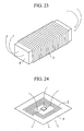
However, in an antenna coil shown in FIG. 24, a magnetic flux is generated in a
vertical direction which passes through the base plate 1 as indicated by an arrow in the
drawing. If such an antenna coil contacts a metal article, a radio wave which is
transmitted toward the antenna coil passes through the base plate 1 and further through
the metal article. Therefore, an eddy current is generated on a metal part due to the
magnetic flux which passes therethrough; thus, the eddy current generates an undesirable
influence. Therefore, there was a problem in that the antenna coil may not be operated
properly. Also, even if the antenna coil can be operated, the loss therein increases; thus,
there was a problem in that an operable distance of the antenna coil may be shortened to
a great extent.
In order to solve such a problem, as shown in FIG. 23, an antenna coil has been
known which comprises a magnetic core member 6 which has a plate shape or a
cylindrical shape and a conductive member 7 which is wound around the magnetic core
member 6 helically. In the antenna coil which is shown in FIG. 23, a magnetic flux is
generated in an axial core direction of the magnetic core member 6 as indicated by an
arrow in the drawing. Therefore, if the antenna coil is attached to a metal article, a
radio wave which is transmitted toward the antenna coil does not pass through the metal
article. Thus, a desirable operation in the antenna coil has been anticipated.
However, the antenna coil shown in FIG. 23 is produced by winding a
conductive member 7 around an outer surface of the magnetic core member 6. Such a
process for winding a conductive member 7 takes times and effort; thus, there has been a
disadvantage from a productivity point of view. Also, an entire antenna coil may be
relative thick because the conductive member 7 is wound around the magnetic core
member 6. If such an antenna coil is attached on a surface of an article, there has been a
problem in that the antenna coil protrudes from the article to a great extent relatively.
Also, there has been other requirement in the conventional technology below.
Conventionally, an antenna coil which is used for an identification tag has been
known such as an antenna coil which is made by winding a lead wire of which surface is
coated by an insulating layer around an approximate square and attaching on a base plate
or by forming an approximate coil main body 202 by removing an unnecessary part from
a conductive layer such as an aluminum film or a copper film which is layered on the
base plate 1 according to an etching method as shown in FIG. 24.
Also, other antenna coil has been known which comprises a magnetic core
member 6 which is formed in a plate shape or a cylindrical shape and a conductive
member 7 which is wound around the magnetic core member 6 helically.
On the other hand, in the antenna coil shown in FIG. 23, a magnetic flux is
generated in an axial core direction of the magnetic core member 6 as indicated by an
arrow in the drawing. Therefore, if the antenna coil is attached to a metal article, a
radio wave which is transmitted toward the antenna coil does not pass through the metal
article. Thus, a desirable operation in the antenna coil has been anticipated. However,
the antenna coil which is shown in FIG. 23 is produced by winding the conductive
member 7 around an outer surface of the magnetic core member 6. Therefore, there has
been a disadvantage in that such a process for winding a conductive member 7 is
complicated relatively. Also, an entire antenna coil may be thick relatively; thus, there
has been a problem in that the antenna coil may protrude from the article if the antenna
coil is attached on a surface of the article.
On the other hand, there were requirements in a conventional transponder.
Conventionally, a transponder has been known which comprises an antenna and an IC
chip which is connected electrically to the antenna so as to store an information for an
article which is an object to be controlled. Also, a transponder which comprises an
antenna and a condenser which is connected to the antenna electrically has been known.
In a transponder in which an IC chip is connected to the antenna, data which are stored in
the IC chip is read out according to a read-out command in a radio wave data
communication such that the transponder is activated by transmitting a radio wave
having a predetermined frequency from a transmitting/receiving antenna from an
interrogator to the antenna, or a read-out operation and writing-in operation for data are
performed such that the data are written in the IC chip according to the write-in
command. For a case in which an entering/exiting operation control is performed, such
a transponder can perform various information control such as identifying an individual
person, and storing times for entrance and exit. Also, for a case in which a
manufacturing process is controlled, the transponder can exchange various information
such as an instructing for processing a product, storing the process, and controlling a
result of product inspection.
On the other hand, the transponder in which a condenser is connected to an
antenna has a specific resonating frequency. The transponder emits a radio wave by
resonating with a radio wave having a predetermined frequency which is transmitted
from the interrogator such that it is identified whether or not the interrogator is a
transponder which has a predetermined frequency by the radio wave. Such a
transponder cannot exchange as various information as the transponder which has an IC
chip. However, such a transponder has an advantage such as a simple structure. For
example, such a transponder can be used for measuring how many people enter/exit a
room if such a transponder is used for room enter/exit controlling operation. If such a
transponder is used for a product manufacturing process, it is possible to measure a
quantity of products which pass therethrough. Here, if transponders having different
resonating frequencies are used, it is possible to measure the quantity of products for a
plurality of classified variations. For example, it is possible to measure the number of
people based on male-or-female base, or adult/child base separately. If such a
transponder is attached to a commercial commodities in a commercial store, it is possible
to monitor a taken-out commodity by disposing an interrogator at an exit. By doing this,
there is a case in which a transponder is used such that it is possible to prevent an illegal
taken-out of the commercial commodities.
These antennae which are used for a conventional transponder are formed by
winding a lead wire of which surface is coated by an insulating layer around an
approximate square helically so as to be attached on a base plate or by performing an
etching operation or a punching operation for removing an unnecessary part of a
conductive layer such as an aluminum which is layered on the base plate or a copper
layer in a helical manner. Such a transponder which has an antenna was fixed on an
article by screws etc. so as to avoid an undesirable influence from an object to be
controlled which is made of a metal member under condition an electrically insulating
spacer having 5 to 10 mm thickness is inserted between the transponder and the object.
However, such a space is relatively thick in the above conventional transponder.
Therefore, an interval between the metal article and the transponder is relatively large
even if the antenna can be formed thin. Thus, there has been a disadvantage in that the
transponder protrude from an article which is an object to be controlled to a great extent.
Therefore, there was a concern that the transponder may contact various members
therearound while the article is transported.
Disclosure of Invention
An object of the present invention is to provide an antenna coil having relatively
high rigidity which can be used in a relatively high frequency.
Other object of the present invention is to provide an antenna coil in which a
space which should be inserted between the antenna coil and an article is unnecessary
such that a protrusion of the antenna coil from an article which is an object to be
controlled can be more reduced than the conventional antenna coil.
In addition, an object of the present invention is to provide a tag antenna coil
which can be formed quite thinly so as to be operated reliably while contacting the metal
article closely. Also, an object of the present invention is to provide a tag antenna coil
which is suitable for a mass production.
Furthermore, other object of the present invention is to provide a tag antenna
coil and an RFID tag using the tag antenna coil of which thickness is maintained thinly
while contacting a metal article closely. Also, an object of the present invention is to
provide a tag antenna coil and an RFID tag using the tag antenna coil which are suitable
for a mass production.
Also, other object of the present invention is to provide an antenna for a
transponder which can be attached to any material condition of a surface directly of an
article which is an object to be controlled without using a spacer.
An invention according to a first aspect of the present patent application is an
improvement for an antenna coil comprising an air-core coil 12 which is formed by a coil
member which is wound on a plane, and a a magnetic core member 13 which is inserted
in the air-core coil 12 so as to be approximately parallel to the plane in the air-core coil
12.
Its characteristic feature is that the magnetic core member 13 is formed by a
composite member of a soft magnetic metal member, a powder of an amorphous member
or a powder of a ferrite member or a flake member and a plastic member or a rubber.
In the antenna coil according to a first aspect of the present invention, the
magnetic core member 13 is formed by a composite material member; thus, such a
magnetic core member 13 is more rigid than a magnetic core member which is formed by
a fragile sintered ferrite. Therefore, it is possible to obtain a rigidity for the antenna coil
by using the magnetic core member 13 which is formed by a composite member.
Also, a soft magnetic metal member, an amorphous member, or a ferrite in the
composite member are dispersed in a plastic member or a rubber so as to be insulated
from each other. Therefore, a magnetic core member 13 which is a composite member
is not a conductive member. Therefore, an eddy current is not generated even if the
magnetic core member 13 receives a high frequency radio wave. Therefore, a Q value
never decreases due to the eddy current even if a radio wave has relatively a high
frequency; thus, it is possible to realize an antenna coil which can be used sufficiently
reliably in a relatively high frequency radio wave.
An invention according to a second aspect of the present patent application is an
antenna coil the magnetic core member 13 which is formed by ejecting the composite
member, or compressing the composite member, or re-shaping a flat rolled composite
member.
In the antenna coil which is disclosed in the second aspect of the present patent
application, it is possible to form the magnetic core member 13 by the composite member.
Thus, it is possible to reduce a protrusion from an article by forming a thin magnetic core
member 13.
An invention according to a third aspect of the present patent application is an
antenna coil in which the magnetic core member 13 is formed by a magnetic coating
which is formed by drying the composite after applying the composite.
In the antenna coil according to the third aspect of the present patent application,
it is possible to obtain a magnetic core member 13 having 0.8 mm or thinner thickness
which is difficult to form in an ejection molding operation and a compressing molding
operation. Thus, it is possible to form quite a thin antenna coil. Therefore, it is
possible to restrict a protrusion of the antenna coil which is attached on the article from
the article to a great extent.
An invention according to a fourth aspect of the present patent application is an
improvement for an antenna coil which comprises an air-core coil 12 which is formed by
a coil member which is wound on a plane, and a magnetic core member 13 which is
inserted in the air-core coil 12 so as to be approximately parallel to the plane in the
air-core coil 12.
Its characteristic feature is that a non-magnetic conductive plate 14 is layered on
a surface of the air-core coil 12 through which the magnetic core member 13 is inserted.
In the antenna coil which is disclosed in the fourth aspect of the present patent
application, an eddy current is not generated on a surface to which the article is attached
under condition that an antenna coils is attached onto the metal article such that the
conductive plate 14 is disposed between the article and the air-core coil 12 and a radio
wave is transmitted; therefore, the conductive plate 14 blocks the radio wave which
passes through the air-core coil 12 so as not to pass through the article. As a result, a
spacer which has been inserted between the antenna coil and the article conventionally is
unnecessary; thus, it is possible to activate the antenna coil reliably. Here, in the
antenna coil according to the fourth aspect, the magnetic core member 13 is formed by an
amorphous sheet or an electromagnetic steel plate which is operable even if the air-core
coil 12 is operated by a relatively low frequency.
An invention according to a fifth aspect of the present patent application is an
antenna coil in which the conductive plate 14 is formed by a copper, a copper alloy, an
aluminum, or an aluminum alloy.
In the antenna coil which is disclosed in the fifth aspect of the present patent
application, it is possible to obtain a conductive plate 14 which can block the
transmission of the radio wave through the article reliably.
An invention according to a sixth aspect of the present patent application is an
antenna coil the conductive plate 14 has 0.01 to 2 mm thickness.
In the antenna coil which is disclosed in the sixth aspect of the present patent
application, an antenna coil which includes the conductive plate 14 can be formed quite
thinly; therefore, the protrusion from the article is restricted even if the article is formed
by a metal member; thus, it is possible to prevent the antenna coil from contacting
various members therearound while transporting the article.
As shown in FIGS. 4 and 5, an invention according to a seventh aspect of the
present patent application is an antenna coil which comprises an insulating member 111
which is formed by an electrically insulating film or an electrically insulating sheet, a
continuous conductive member 112 which has forwarding sections 112a and returning
sections 112b which are formed alternatively so as to wind on a surface of the insulating
member 111, a first magnetic core member 113 which is bonded on a back surface of the
insulating member 111 so as to cover the forwarding section 112b from the back surface
of the insulating member 111 without overlapping the forwarding section 112a.
In the antenna coil which is disclosed in the seventh aspect of the present patent
application, the first magnetic core member 113 is bonded to a back surface of the
insulating member 111; therefore, the magnetic flux which is generated by an electric
current which passes the conductive member 112 passes the first magnetic core member
113 so as to shape a loop which is indicated in a true-line arrow in FIG. 4 so as to be
parallel with a surface of the article 18. Even if a surface of the article to which the
antenna coil is attached is a metal member, the antenna coil operates reliably without
receiving an undesirable influence from the metal member.
Also, the first magnetic core member 113 is bonded onto a back surface of the
insulating member 111 so as to cover the conductive member 112b from a back of the
insulating member 111 without overlapping the forwarding sections 112a. Therefore, as
shown by a dotted arrow in FIG. 4 in an enlarged manner, the magnetic flux which passes
through the first magnetic core member 113 passes above the forwarding sections 112a
while a part of the magnetic flux disperses in an end section there. The magnetic flux
returns back to the neighboring first magnetic core member 113 again such that a
continuous conductive member 112 which includes the forwarding sections 112a and the
112b forms the antenna coil which is wound around a part of the magnetic flux.
An invention according to an eighth aspect of the present patent application is an
antenna coil as shown in FIGS. 6 and 7 in which a second magnetic core member 114
covers the forwarding section 112a so as not to overlap the returning section 112b on the
surface of the insulating member 111 such that an end section of the second magnetic
core member 114 is bonded so as to overlap an end section of the first neighboring
magnetic member 113, and the second magnetic core member 114 introduces a magnetic
flux which passes through the first magnetic core member 113 onto a surface of the
insulating member 111 on the forwarding section 112a.
In the antenna coil according to the eighth aspect of the present patent
application, the magnetic flux which passes through the first magnetic core member 113
passes through the first magnetic core member 113 and the second magnetic core
member 114 while moving the first magnetic core member 113 and the second magnetic
core member 114 alternatively as shown by a true-line arrow in FIG. 6. Therefore, the
forwarding sections 112a and the 112b exist on a top surface and a back surface of the
magnetic flux. The continuous conductive member 112 which includes the forwarding
sections 112a and the conductive member 112b form the antenna coil unitarily which is
wound around the magnetic flux. As a result of this, it is possible to obtain an antenna
coil 10 which has the same characteristics as a conventional antenna coil which has been
produced by winding a lead wire around a magnetic core member relatively easily.
Thus, it is possible to improve productivity in a mass production better than a case for the
conventional antenna coil which has been produced by winding a lead wire therearound.
An invention according to a ninth aspect of the present patent application is an
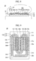
antenna coil in which a plurality of conductive lines 21, 22 are disposed so as to wind on
a surface of the insulating member 111 in a predetermined interval along with each other
in the continuous conductive member 112, and an end section of the conductive line 21 is
connected to a starting end section of the neighboring conductive line 22 as shown in
FIGS. 8 and 9.
In the antenna coil which is described in the ninth aspect of the present patent
application, the quantity of forwarding sections 21a and 22a and returning sections 21b
and 22b which exist alternatively on a top surface and a back surface of the magnetic flux
which passes through the first magnetic core member 113 and the second magnetic core
member 114 are increased; thus, it is possible to increase so-called a turning number
easily. By increasing the turning number, it is possible to improve the characteristics in
the antenna coil.
An invention according to a tenth aspect of the present patent application is an
antenna coil in which the continuous conductive member 112 is formed on a surface of
the insulating member 111 by etching a conductive film which is bonded on an entire
surface of the insulating member 111 in a predetermined pattern, or performing a screen
printing operation or a vapor deposition operation of the conductive member on a surface
of the insulating member 111 in a predetermined pattern.
In the antenna coil which is described in the tenth aspect of the present patent
application, it is possible to form the conductive member 112 on a surface of the
insulating member 111 relatively easily; thus, it is possible to improve the productivity
for the antenna coil furthermore.
An invention according to an eleventh aspect of the present patent application is
an antenna coil in which either one or both of the first magnetic core member 113 or the
magnetic core member 114 is formed by a soft magnetic metal member, a powder or a
flake which is formed by an amorphous member or a ferrite member, a plastic composite
member, a plate or a film which is formed by a soft magnetic metal member, an
amorphous film or its layered member, or a ferrite member.
In the antenna coil which is described in the eleventh aspect of the present patent
application, the first magnetic core member 113 or the second magnetic core member 114
is relatively thin. By forming the first magnetic core member 113 and the second
magnetic core member 114 which form an entire part in a thickness direction of the
antenna coil thinly, it is possible to form an entire antenna coil thinly.
An invention according to twelfth aspect of the present patent application is an
antenna coil in which either one or both of the first magnetic core member 113 and the
magnetic core member 114 is formed by a magnetic coating which is formed by applying
an ink or an applying member which include a magnetic powder onto the insulating
member 111 and drying the ink or the applying member.
In the antenna coil which is described in the twelfth aspect of the present patent
application, it is possible to obtain the magnetic core members 113 and 114 having a
thickness such as 0.8 mm or thinner which is difficult to form in an injection molding
operation. Thus, it is possible to form the thickness of the antenna coil very thinly.
Therefore, it is possible to restrict the protrusion of the antenna coil from the article when
the antenna coil is attached onto the article very much.
An invention according to a thirteenth aspect of the present patent is an antenna
coil in which a conductive member 116 made of a sheet member or a plate member is
bonded onto a back surface of the insulating member 111 so as to cover the first magnetic
core member 113.
In the antenna coil which is described in the thirteenth aspect of the present
patent application, the conductive member 116 is disposed between the conductive
member 112 and the article; therefore, the conductive member 116 blocks the
transmission of the radio wave toward the article. Therefore, there is not generated a
loss due to an eddy current etc. which is generated on a surface of the metal member
even if a surface of the article is formed by a metal member. As a result, it is possible to
operate the antenna coil reliably.
An invention according to a fourteenth aspect of the present patent
application is a tag antenna coil which comprises a coil main body 211a which is
formed by a conductive coil member 211 which is wound in a plane, and a magnetic core
member 213 made of a sheet member or a plate member which is bonded on a surface of
the coil main body 211a such that an end 213a of the magnetic core member 213 is
disposed in a central section 211b which is surrounded by the coil main body 211a and
another end 213b of the magnetic core member 213 is disposed at an outside of the coil
main body 211a so as to cross a part of the coil main body 211a as shown in FIGS. 11
and 12.
In the tag antenna coil which is described in the fourteen aspect of the present
patent application, the magnetic core member 213 is bonded so as to be across a part of
the coil main body 211a; therefore, it is possible to enhance the Q value of the antenna
coil. Also, the magnetic flux which is generated by an electric current which passes the
coil main body 211a which is formed by the conductive coil member 211 passes through
its magnetic core member 213 so as to shape a loop which is shown by a true-line arrow
in FIG. 11. Therefore, the direction of the magnetic flux is parallel with a surface of the
article; thus, an eddy current which is generated on a metal member of a surface of the
article is restricted even if the tag antenna coil is attached onto a surface of the article
which is formed by a metal member. Thus, the antenna coil is operated reliably.
An invention according to a fifteenth aspect of the present patent application is a
tag antenna coil in which the coil main body 211a is formed by punching a conductive
plate or a conductive film.
In the tag antenna coil according to the fifteenth aspect of the present patent
application, it is possible to form the coil main body 211a easily; thus, it is possible to
improve the productivity for the antenna coil.
An invention according to a sixteenth aspect of the present patent application is
a tag antenna coil in which the coil main body is formed by etching a conductive film
which is bonded on an entire main surface of an electrically insulating film or a sheet 212
in a predetermined pattern, or performing a screen printing operation or a vapor
deposition operation of the conductive member on an entire main surface of the
electrically insulating film or the sheet 212 in a predetermined pattern.
In the tag antenna coil according to the sixteenth aspect of the present patent
application, the conductive coil member 211 is disposed on an electrically insulating film
212 or a sheet; therefore, it is possible to handle it easily. Therefore, it is possible to
obtain an antenna coil by an easy operation such as only layering and attaching the
magnetic core member 213 onto another main surface of a film or a sheet 212. Thus, it
is possible to improve the productivity in a mass production with compared to a case for
a conventional antenna coil which is shown in FIG 23 in which a lead wire is wound
around an outer surface of a magnetic core member.
An invention according to a seventeenth aspect of the present patent application
is a tag antenna coil in which the magnetic core member 213 is a magnetic coating which
is formed by applying a soft magnetic metal member, a powder or a flake which is
formed by an amorphous member or a ferrite member, a plastic composite member, a
plate or a film which is formed by a soft magnetic metal member, an amorphous film or
its layered member, or a ferrite member, or an ink or an applying member which include
a magnetic powder onto an electrically insulating film or a sheet and drying the ink or the
applying member.
In the tag antenna coil according to the seventeenth aspect of the present patent
application, the magnetic core member 213 is relatively thin. Thus, it is possible to
form an entire antenna coil thinly by forming the magnetic core member 213 thinly
which occupies a most part of the antenna coil in a thickness direction.
An invention according to an eighteenth aspect of the present patent application
is a tag antenna coil in which the magnetic core member 213 is a magnetic coating which
is formed by applying an ink or an applying member which include a magnetic powder
onto another main surface of the electrically insulating film or a sheet 212 and drying the
ink or the applying member.
In the tag antenna coil according to the eighteenth aspect of the present patent
application, it is possible to obtain the magnetic core member 213 having 0.8 mm or
thinner thickness which is difficult to form in the injection molding operation and a
compressing molding operation. Therefore, it is possible to form the antenna coil with a
very thin thickness. Also, it is possible to restrict the protrusion of the antenna coil
from the article very much when the antenna coil is attached onto the article.
An invention according to a nineteenth aspect of the present patent application is
a tag antenna coil in which a conductive member 216 made of a sheet member or a plate
member is bonded onto a surface of the coil main body 211a so as to cover the magnetic
core member 213.
In the tag antenna coil according to the nineteenth aspect of the present patent
application, its conductive member 216 is disposed between the coil main body 211a
which is formed by the conductive coil member 211 and the article; therefore, the
conductive member 216 block a transmission of the radio wave toward the article.
Therefore, the antenna coil can be operated reliably without generating a loss due to an
eddy current which is generated on a metal surface even if a surface of the article is
formed by a metal member.
An invention according to a twentieth aspect of the present patent application is
an RFID tag which comprises an antenna coil 10 which is attached to an article 18, and
an IC chip which is connected to the antenna coil 10 electrically such that a specific
information for each article 18 is stored in the IC chip, such that the antenna coil 10 is
attached to the article such that the magnetic core member 213 is disposed between the
article 18 and the coil main body 211a.
In the RFID tag according to the twentieth aspect of the present patent
application, the magnetic flux which is generated by an electric current which passes the
coil main body 211a passes mainly through the magnetic core member 13 when the
magnetic core member 213 is disposed so as to neighbor the article 18; thus, few
magnetic flux passes through the article 18. Therefore, the antenna coil 10 hardly
receive its undesirable influence with regardless to whether or not the article 18 is a
metal member. Thus, the RFID tag in which the antenna coil 10 is used is operated
reliably.
An invention according to a twenty-first aspect of the present patent application
is an improvement of a transponder antenna as shown in FIGS. 15 and 16 which is
connected to an IC chip 313 or a condenser electrically so as to be attached to an article
311.
Its feature is that it comprises a conductive plate member 314a of which back
surface is attached to the article 311, a coil main body 314b which is wound helically on
a surface of the conductive member 314a via an insulating member 316 and fixed thereon
such that a turning number and a coil diameter are adjusted so as to realize a
predetermined characteristic value under a wound condition.
In the transponder antenna according to the twenty-first aspect of the present
patent application, the coil main body 314b is adjusted so as to obtain a predetermined
characteristics value under condition that the coil main body 314b is wound around an
outer surface of the conductive plate member 314a. Therefore, if an IC chip is
connected to the antenna in the transponder, it is possible to activate the transponder 12
reliably by transmitting a radio wave having a predetermined frequency from a
transmitting/receiving antenna in an interrogator which is not shown in the drawing to
the antenna 314. If a condenser is connected to the antenna in the transponder, it is
possible to resonate with the radio wave which is transmitted from the interrogator
reliably. Also, in the antenna 314, the coil main body 314b is wound around an outer
surface of the conductive plate member 314a in advance; thus, a predetermined
characteristic value is obtained. Therefore, if the antenna 314 is attached to a metal
article directly which is an object to be controlled, the coil main body 314b does not
receive an undesirable influence from the metal article; therefore, the characteristic value
in the coil main body 314b does not vary to a great extent. Therefore, a space which
has been necessary for attaching the antenna 314 to the metal article is not necessary;
thus, it is possible to prevent the transponder 12 from protruding from the article which is
an object to be controlled to a great extent.
For a shape of the conductive plate member 314a, it is possible to name a sheet,
a plate, a helical member both end of which are connected such that an electric resistance
per 1 cm width and 1 cm length is 5Ω or less.
Also, as shown in FIG. 15 in an enlarged manner, for a material for the
insulating member 316, non-conductive material is preferable such as a sheet, a plate, or
a film which is formed by a polyethylene member or a polyethylene terephthalate
member.
In such a case, it is acceptable if the conductive plate member 314a may be a
conductive coating which is made by applying a conductive ink onto a back surface of
such a insulating member 316 and drying thereof. Also, it is acceptable if the
conductive plate member 314a may be a conductive plating layer or a conductive vapor
deposition layer such as a Cu or Al which are made by layering on a back surface of the
insulating member 316. In such a case, it is preferable that an insulating member 316
having 0.01 to 5 mm thickness be used such that an interval between the conductive plate
member 314a and the coil main body 314b should be 0.01 to 5 mm.
Furthermore, as shown in FIG. 17, it is possible to forma a hole 314c in a section
which is surrounded by the coil main body 314b in the conductive plate member 314a.
As shown in FIG 19, it is possible to dispose a soft magnetic member 26 between the
conductive plate member 314a and the coil main body 314b. In a case in which a hole
314c is formed on the conductive plate member 314a which is in a central part of the coil
main body 314b, if an eddy current is generated in the conductive plate member 314a due
to a radio wave which passes through the coil main body 314b, such an eddy current is
generated in a narrow range which neighbors the coil main body 314b because of the
hole 314c; thus, it is possible to restrict a decrease in the Q value in the coil main body
314b. On the other hand, if the soft magnetic member 26 is disposed between the
conductive plate member 314a and the coil main body 314b, the coil main body 314b is
electrically separated from the conductive plate member 314a by the soft magnetic
member 26; thus, the Q value in the coil main body 314b improves. Therefore, it is
possible to adjust the turning number or the turning diameter of the coil main body 314b
relatively easily so as to obtain a predetermined characteristic value.
An invention according to twenty-second aspect of the present patent application
is an improvement for a transponder antenna as shown in FIG. 20 which is connected to
an IC chip 313 or a condenser electrically so as to be attached to the article 311.
Its characteristic feature is that the transponder antenna comprises a flat pate soft
magnetic member 26 of which back surface is attached onto the article 311 and a coil
main body 314b of which turning number and turning diameter are adjusted such that a
predetermined characteristic value can be obtained under condition that it is wound
around a surface of the soft magnetic member 26 so as to be fixed therearound.
In the transponder antenna according to the twenty-second aspect of the present
patent application, when a radio wave is transmitted under condition that an antenna 314
is attached onto the article 311 which is made by a metal member, the soft magnetic
member 26 blocks the radio wave so as not to pass toward the metal part; thus, an eddy
current is not generated in such a metal part. As a result, even if the article 311 is
formed by a metal member, a space which has been necessary is not necessary.
Therefore, it is possible to prevent the antenna 314 from contacting the members
therearound while transporting the article 41.
Here, it is preferable that a product of a transmission rate of the soft magnetic
member 26 and a thickness represented in a unit such as mm indicates 0.5 or larger.
Also, it is preferable that the soft magnetic member 26 is formed by any one of members
such as an amorphous alloy, a Permalloy, a magnetic steel, a silicon steel, a sendust alloy,
a quench solidified member for Fe-Al alloy or a soft magnetic ferrite, a casted member, a
rolled strip member, a forged member, or a sintered member. Also, it is preferable that
the soft magnetic member 26 is a coating of a powder of a soft magnetic metal member
or a soft magnetic ferrite, or composite member of a flake, a plastic member, or a rubber,
or a applying member of a powder of a soft magnetic metal member or a powder of a soft
magnetic ferrite, or a flake. Furthermore, it is acceptable if the soft magnetic member
26 is a sheet which is formed by bonding a plurality of flakes which are made of a soft
magnetic metal member or a soft magnetic ferrite onto a surface of a plastic base sheet
such that the flakes contact closely each other. Also, it is acceptable if the soft magnetic
member 26 is a sheet which is formed by bonding a plurality of flakes which are made of
a soft magnetic metal member or a soft magnetic ferrite onto a surface of a plastic base
sheet such that the flakes contact closely each other, covering the flakes by a plastic
cover sheet, and attaching the base sheet and the cover sheet.
BRIEF DESCRIPTION OF THE DRAWINGS
FIG. 1 is a plan view of an antenna coil according to the present patent
application.
FIG. 2 is a cross section viewed in a line A-A shown in FIG. 1 so as to describe
the condition in which the antenna coil is attached onto an article.
FIG. 3 is a plan view for an air-core coil in the antenna coil.
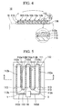
FIG. 4 is a cross section viewed in a line A-A shown in FIG. 5 so as to describe
an antenna coil according to a third embodiment of the present patent application.
FIG. 5 is a plan view for an antenna coil.
FIG. 6 is a cross section which corresponds to the FIG 4 in which an antenna
coil according to a fourth embodiment of the present patent application is shown.
FIG. 7 is a plan view for an antenna coil.
FIG. 8 is a cross section which corresponds to the FIG 4 in which an antenna
coil according to a third embodiment of the present patent application is shown.
FIG. 9 is a plan view for an antenna coil.
FIG 10 is a plan view for an antenna coil which has a conductive member which
comprises three conductive lead wires.
FIG. 11 is a cross section viewed in a line A-A shown in FIG. 12 which shows an
antenna coil according to a fifth embodiment of the present patent application.
FIG 12 is a plan view for an antenna coil.
FIG. 13 is a cross section which corresponds to the FIG. 11 in which an antenna
coil according to a sixth embodiment of the present patent application is shown.
FIG. 14 is a plan view for an antenna coil.
FIG. 15 is a plan view for a transponder which includes an antenna according to
a seventh embodiment of the present invention.
FIG 16 is a cross section viewed in a line A-A in FIG 15.
FIG. 17 is a plan view which corresponds to FIG. 15 which describes a
transponder which includes an antenna in which a hole is formed in its conductive
member.
FIG. 18 is a cross section which corresponds to FIG. 16 which describes an
antenna.
FIG. 19 is a cross section which corresponds to FIG. 16 which shows an antenna
according to a second embodiment in which a soft magnetic member is disposed.
FIG. 20 is a cross section which corresponds to FIG 16 which shows an antenna
according to a ninth embodiment in which the soft magnetic member is attached to an
article.
FIG. 21 is a plan view which corresponds to FIG. 15 which shows a case in
which a coil main body has a rectangular shape.
FIG. 22 is a view showing a condition for confirming operations in a transponder
in the embodiments.
FIG 23 is an isometric view for showing a conventional antenna coil which has
a conductive member which is wound around an magnetic core member helically.
FIG. 24 is an isometric view for showing a conventional antenna coil which
comprises a helical coil section.
BEST MODE FOR CARRYING OUT THE INVENTION
Next, embodiments of the present invention are explained with reference to
drawings below.
As shown in FIGS. 1 and 2, an antenna coil 10 according to the present
invention comprises an air-core coil 12 which is formed by winding a conductive
member 11 helically in a plane and a flat plate magnetic core member 13 which is
inserted into the air-core coil 12 so as to be approximately parallel with a plane in the
air-core coil 12. The air-core coil 12 is formed by winding a coated lead wire which
forms the conductive member 11 or by punching or etching a conductive plate in a
predetermined pattern. Also, the air-core coil 12 can be formed by etching a copper
film which is layered on an electrically insulating film or a sheet or by performing a
screen printing operation or a vapor deposition operation for a conductive member on a
main surface of an electrically insulating film or a sheet. In such a case, it is necessary
to form a hole such as a hole in a doughnut through which a magnetic core member 13
should be inserted in a central part of the air-core coil 12 on an electrically insulating
film or a sheet.
For a representative example, a case in which a air-core coil 12 is formed by
etching a copper layer which is layered on an electrically insulating film 12a is explained.
First, a film 12a which has copper films on both surfaces of the of the film 12a is
prepared. As shown in FIG. 3, a first through hole 12b is formed near a central part of
the film 12a. A second through hole 12c is formed near an outer marginal section of a
film near the first through hole 12b. After that, an anti-etching paint is printed on both
surfaces of the film 12a by a silk screen method. The anti-etching paint is applied on a
surface of the film 12a in a rectangular helical manner such that a circumferences of the
first through hole 12b and the second through hole 12c, and the first through hole 12b
should be inner ends and an outer end should be disposed near the second through hole
12c. Consequently, a wide paint section is formed on an outer end of the coil. In
addition, an anti-etching paint is applied so as to be dried on another surface of the film
12a such that the first through hole 12b and the second through hole 12c communicate
therebetween. Consequently, a copper film on which a paint is not applied is removed
by an etching operation; thus, a copper film on a section on which an anti-etching paint is
applied remains on the film 12a.
After that, the anti-etching paint is removed from the copper film which remains
on the film 12a. Also, a first terminal 11a and a second terminal 11b around the first
through hole 12b and the second through hole 12c, a helical coil section 11c in a
rectangular coil manner having an inner end such as a first terminal 11a, and an
intermediate terminal 11d which is formed by a wide section on an outer end of the coil
section 11c are formed on a surface of the film 12a by a remaining copper film. In
addition, a connective conductive member 11e which connects the first through hole 12b
and the second through hole 12c on another surface of the film 12a by the remaining
copper film. After that, inner surfaces of the first through hole 12b and the second
through hole 12c are plated. The first terminal 11a and the connective conductive
member 11e are connected. The second terminal 11b and the connective conductive
member 11e are connected. Thus, the first terminal 11a and the second terminal 11b are
connected electrically via the connective conductive member 11e. After that, a hole 12d
through which the magnetic core member 13 is inserted is formed by a pressing
operation; thus, an air-core coil 12 is obtained. In such an air-core coil 12 which is
obtained by etching a copper film which is layered on the electrically insulating film 12a,
it is possible to form a tag by connecting an IC or a condenser between the second
terminal 11b and the intermediate terminal 11d.
Referring back to FIGS. 1 and 2, the magnetic core member 13 is formed by a
composite member. The composite member is formed by a soft magnetic metal member,
an amorphous or a ferrite powder or a flake, or a plastic member or a rubber. For such a
soft magnetic metal member, it is preferable to use a carbonyl iron powder or a reduced
iron powder because a fine powder can be obtained easily. The reduced iron powder
can be obtained by performing a low-temperature reduction operation for a fine iron
oxide in a hydrogen gas. Also, for such a soft magnetic metal member, it is acceptable
if an iron, Permalloy, and amorphous powder which are produced according to an
atomizing method be used. Also, it is acceptable if an amorphous alloy flake be used
which is formed by crushing a soft magnetic metal powder which is obtained by an
atomizing method by using a crushing device or a ball-end mill and colliding a powder
and a melt alloy grain which are mechanically flattened onto a surface of a copper which
is cooled by a water.
On the other hand, it is preferable to use an insulating resin such as an acrylic
member, a polyester, a polyvinyl chloride, a polyethylene, a polystyrene, and an epoxy
for such a plastic member. Also, it is possible to use any synthetic rubber such as a
natural rubber and a butyl rubber for a rubber.
For a method for producing a composite member, a method is appropriate in
which a mixture of a soft magnetic metal member, a powder of an amorphous member or
a powder of a ferrite member or a flake member and a plastic member or a rubber is
kneaded so as to form a pellet for forming in a predetermined shape by an injection
molding operation or a compressing molding operation. When the magnetic core
member 13 is formed in an injection molding operation or a compressing molding
operation, a flat plate stage section 13a can be formed in the magnetic core member 13
unitarily with the air-core coil 12 as shown in FIG 2 simultaneously with its molding.
Thus, it is possible to obtain a relatively thin antenna coil 10 relatively easily. In such a
case, a magnetic field is established in a magnetic direction when the above mixture is
injected or compressed so as to dispose the soft magnetic metal members in arrays, the
characteristics for the antenna coil 10 may be improved further. Also, it is acceptable if
the above mixture may be flattened by a roll so as to be slits, compressed to be deformed,
or casted in a mold. In any of the above cases, the characteristics are improved by
disposing the soft magnetic metal members in arrays by establishing a magnetic field.
When a soft magnetic metal member or an amorphous powder are used, it is
preferable that its diameter should be in a range of 0.6 to 100 µm. More preferably, it
should be in a range of 1 to 43 µm.
If the soft magnetic metal member or the amorphous are flakes, its thickness
should preferably be in a range of 0.1 to 10 µm. More preferably, its thickness should
be in a range of 0.3 to 5 µm. If the diameter of the soft magnetic metal member or the
amorphous powder is smaller than the above ranges, the powder intends to be oxidized
more easily. If it is larger than the above ranges, there is a problem in that a loss due to
an eddy current increases. For a mixture ratio of the composite member, 10 to 95 % of
the amorphous or the ferrite should be preferable. More preferably, it should be 40 to
90 %. The rest of the ratio indicates a plastic or a rubber. If the soft magnetic metal
member, the amorphous, or the ferrite are contained less than the above range, there is a
problem that a magnetic permeability is too low. If the soft magnetic metal member, the
amorphous, or the ferrite are contained more than the above range, the soft magnetic
metal member, the amorphous, or the ferrite contact with each other; thus, the magnetic
core member 13 may be conductive; therefore, there is a concern that the loss increases.
On the other hand, a non-magnetic conductive plate 14 is layered on a surface of
the air-core coil 12 through which the magnetic core member 13 is inserted. The
conductive plate 14 is made of a copper, a copper alloy, or an aluminum, or an aluminum
alloy so as to be bonded on a surface of the air-core coil 12 through which the magnetic
core member 13 is inserted. The conductive plate 14 is disposed between the air-core
coil 12 and the article 16 so as to seal the air-core coil 12 from the article 16
electro-magnetically. Thickness of the conductive plate 14 is 0.01 to 2 mm. If the
thickness of the conductive plate 14 is smaller than 0.01, an essential effect such as
electro-magnetic sealing cannot be anticipated. If the thickness of the conductive plate
14 exceeds 2 mm, an interval between the article 16 and the air-core coil 12 may
increase; thus, there is a disadvantage that the air-core coil 12 may protrude from the
article 16 to a great extent.
In the antenna coil 10 which is formed as above, the magnetic core member 13
is formed by a composite member. Therefore, the antenna coil 10 is more rigid with
compared to a magnetic core member which is formed by a fragile
ferrite-sintered-member. Therefore, it is possible to obtain a rigidity in the antenna coil
by using the magnetic core member 13. Also, the soft magnetic metal member, the
amorphous or the ferrite are dispersed in a plastic or a rubber and insulated from each
other. Therefore, an entire magnetic core member 13 is not conductive; thus, an eddy
current is not generated even if it receives a high frequency radio wave. Therefore,
even if a frequency of a radio wave which is emitted from a transmitting antenna which
is not shown in the drawing is relatively high such as several MHz to several ten MHz,
the Q value does not decrease due to the generated eddy current. As a result, the
antenna coil 10 of the present invention is relatively rigid. Compatibly, it is possible to
use the antenna coil 10 sufficiently in a relatively high frequency.
In particular, in the present embodiment, the non-magnetic conductive plate 14
is layered on a surface of the air-core coil 12 through which the magnetic core member
13 is inserted; therefore, if the air-core coil 12 is attached onto the article 16 via the
conductive plate 14, the conductive plate 14 is disposed between an attaching surface of
the article 16 and the air-core coil 12. Therefore, the air-core coil 12 is blocked from
the article 16 electrically; thus, it is possible to prevent the self-inductance in the air-core
coil 12 from varying and the Q value from decreasing perfectly. In particular, it is
effective for a case in which the article 16 is formed by a ferromagnetic member. This
is because of following reasons. That is, if the above conductive plate 14 is bonded
onto the air-core coil 12 which faces to the attaching surface of the article 16 which is
made of a ferromagnetic member, the magnetic flux which is about to pass through the
article 16 among the magnetic flux which is emitted from the magnetic core member 13
passes above the conductive plate 14 which has a high conductivity. Also, the
conductive plate 14 is a non-magnetic member; therefore, there is very few hysteresis
loss; thus, very few eddy current is generated. Thus, the article 16 which is made of a
ferromagnetic member does not affect the air-core coil 12 undesirably.
Here, in the above embodiment, an example is shown in which the magnetic
core member 13 is formed by performing an injection molding operation or a
compressing molding operation, or a flattening molding operation for the composite
member. It is acceptable if the magnetic core member 13 may be formed by applying
and drying the composite member. In such a case, it is preferable to apply and dry the
composite member on an insulating resin film or a sheet which are not shown in the
drawing. Here, it is preferable that the thickness of the insulating resin film or the sheet
should by 100 to 200 µm when the magnetic coating is formed. More preferably, it
should be 30 to 150 µm. Also, the thickness of the formed magnetic coating should be
10 to 800 µm. More preferably, it should be 30 to 300 µm. Here, if it is not possible
to obtain a predetermined thickness in a single applying operation for a paint, it is
possible to obtain a desirable thickness of coating by applying and drying the same paint
repeatedly. By doing this, the rigidity for the magnetic core member is obtained by an
insulating resin film or a sheet if a magnetic core member which is made of a magnetic
coating is formed on a surface of the insulating resin film or the sheet. Simultaneously,
it is possible to obtain a magnetic core member 13 which having 0.8 mm thickness or
thinner which is difficult to form in an injection molding operation. Furthermore, it is
possible to obtain a thin antenna coil 10.
Next, examples of the present invention are explained with reference to a
comparative example in detail below.
<Example 1>
First, an air-core coil is formed on a main surface of an electrically insulating
film. For the electrically insulating film, a polyimide film having 50 mm longitude and
50 mm latitude and 50 µm thickness is used. A copper film having 35 µm thickness is
layered to be bonded on a main surface of the polyimide film so as to etch the copper
film. By doing this, an air-core coil which is wound helically in a four-time rectangular
manner is formed on a main surface of the polyimide film. The conductive member
which forms the air-core coil is formed so as to have 0.8 mm width. An outer shape of
the air-core coil is formed so as to have a dimension such as 18 mm × 47 mm.
Next, a mixture of 92 weight % of a carbonyl iron powder and a nylon resin is
injected into a mold. By doing this, a magnetic core member 13 which is formed by a
composite member having 0.87 mm thickness and 35 mm × 52 mm dimension is
obtained. Consequently, a hole having 35 mm × 1 mm of dimension is formed on an
electrically insulating film which is disposed in a center of the air-core coil. The
magnetic core member 13 is inserted into the hole so as to be approximately parallel with
a plane of the air-core coil; thus, an antenna coil is obtained. A comparative example 1
is an antenna coil which has a magnetic core member which is obtained by injecting the
composite member into a mold.
<Example 2>
An air-core coil which is the same as that of the example 1 is formed on an
electrically insulating film which is the same as the electrically insulating film of the
example 1 by the same conductive member as that of the example 1 by the process which
is the same as the process in the example 1. Also, a paint is prepared in which 70
weight % of amorphous flake, 10 weight % of acrylic resin, and 20 weight % of ethyl
acetate as a solvent are mixed. The paint is applied and dried on an entire main surface
of a film which is formed by a polyethylene terephthalate having 0.1 mm thickness.
Thus, a magnetic coating having 0.1 mm thickness is obtained. A film on entire main
surface of which the magnetic coating is formed is cut in to a dimension of 35 mm × 60
mm with the magnetic coating. Thus, the magnetic core member 13 which is made of a
magnetic coating which is formed by applying and drying the composite member is
obtained. Consequently, a hole having 35 mm × 1 mm of dimension is formed on an
electrically insulating film which is disposed in a center of the air-core coil. The
magnetic core member 13 is inserted into the hole so as to be approximately parallel with
a plane of the air-core coil; thus, an antenna coil is obtained. An example 2 is an
antenna coil which has a magnetic core member which is formed by the magnetic
coating.
<Comparative Example 1>
An air-core coil which is the same as that of the example 1 is formed on an
electrically insulating film which is the same as the electrically insulating film of the
example 1 by the same conductive member as that of the example 1 by the process which
is the same as the process in the example 1. Also, a magnetic core member which is
formed by a layered member of an amorphous film having 4 layers of amorphous films
having 10 mm × 60 mm of dimension and 20 µm thickness is prepared. Consequently,
a hole having 35 mm × 1 mm of dimension is formed on an electrically insulating film
which is disposed in a center of the air-core coil. The magnetic core member 13 is
inserted into the hole so as to be approximately parallel with a plane of the air-core coil;
thus, an antenna coil is obtained. A comparative example 1 is an antenna coil which has
a magnetic core member which is formed by the layered member of the amorphous film.
<Comparative Test>
Measurement terminals in a measurement device (Model 4396 commercially
available under trade mark which is registered by HEWLETT PACKARD) for measuring
characteristics in a coil are connected to both ends of the air-core coil in the antenna coils
in the examples 1 and 2, and a comparative example. An L value and Q value in the
air-core coils are measured respectively which correspond to the predetermined
frequency by the measurement device.
Also, an aluminum plate as an article is prepared which has 100 mm x 100 mm
dimension and 0.16 mm thickness. IC chips are connected to the air-core coils in the
comparative example 1 and examples 1 to 3 respectively so as to form tags which can be
operated by a frequency of 13.56 MHz by the IC chips and the antenna coil. It is
confirmed whether or not the tags are operated if the tags are disposed on surfaces of the
aluminum plate respectively. The result is shown in a TABLE 1.
| | Example 1 | Example 2 | Example 3 |
| Magnetic Core Member | Composite Member | Magnetic Coating | Amorphous Film |
| Predetermined Frequency (MHz) | L (µH) | Q | L (µH) | Q | L (µH) | Q |
| 1 | 1.556 | 9.1 | 1.405 | 8.1 | 1.886 | 5.4 |
| 2 | 1.535 | 16.0 | 1.385 | 13.8 | 1.771 | 6.0 |
| 3 | 1.527 | 21.4 | 1.376 | 17.8 | 1.696 | 6.6 |
| 4 | 1.524 | 26.2 | 1.371 | 20.8 | 0.164 | 6.6 |
| 5 | 1.525 | 30.8 | 1.367 | 23.2 | 1.665 | 6.6 |
| 6 | 1.526 | 34.9 | 1.368 | 25.1 | 1.576 | 6.7 |
| 7 | 1.529 | 38.1 | 1.368 | 26.4 | 1.550 | 6.6 |
| 8 | 1.532 | 41.3 | 1.367 | 27.8 | 1.533 | 6.6 |
| 9 | 1.538 | 44.5 | 1.379 | 28.3 | 1.517 | 6.6 |
| 10 | 1.543 | 47.0 | 1.374 | 30.1 | 1.502 | 6.7 |
| 11 | 1.549 | 49.3 | 1.379 | 31.1 | 1.490 | 6.7 |
| 12 | 1.558 | 52.2 | 1.304 | 31.7 | 1.483 | 6.7 |
| 13 | 1.567 | 53.9 | 1.389 | 31.9 | 1.476 | 6.7 |
| 14 | 1.576 | 55.6 | 1.396 | 32.6 | 1.470 | 6.8 |
| 15 | 1.587 | 57.6 | 1.403 | 32.6 | 1.467 | 6.7 |
| 20 | 1.654 | 61.6 | 1.445 | 32.1 | 1.404 | 6.7 |
| Confirmation of Operation | Operated | Operated | Operated |
As understood from the TABLE 1, it is understood that the Q value is improved
by comparing the Examples 1 and 2 to the comparative example 1. The reason for this
is estimated that the magnetic core member is an amorphous film in the comparative
example 1; thus, an eddy current is generated on the magnetic core member. On the
other hand, in the examples 1 and 2, it is estimated that the magnetic core member is
formed by a composite member; therefore, an eddy current is not generated on the
magnetic core member. Also, the tag in which the antenna coils of the examples 1 and 2
are connected to the IC chip can be operated even if the tag is disposed on a surface of
the aluminum plate. In contrast, the tag in which the IC chip is connected to the
antenna coil of the comparative example 1 does not operate. It is also estimated that
this is because the L value in the antenna coil of the comparative example 1 varies
according to whether or not the eddy current is generated; thus, the resonation frequency
varies and the energy is absorbed; thus, a loss is generated.
Next, a second embodiment of the present invention is explained with reference
to drawings.
As shown in FIGS. 4 and 5, the antenna coil 10 comprises an insulating member
111 which is formed by an electrically insulating film or an electrically insulating sheet, a
conductive member 112 which is formed by a conductive member to wind on a surface of
the insulating member 111, and a first magnetic core member 113 which is bonded on a
back surface of the insulating member 111. The insulating member 111 is formed in a
rectangular shape by an electrically insulating plastic film or a sheet, or a paper. It is
preferable that the insulating member 111 should be formed by a plastic film or a plastic
sheet such as a polyester or a polyimide. The conductive member 112 can be formed on
a surface of the insulating member 111 by etching a conductive film which is bonded on
a surface of the insulating member 111, bonding a conductive film which is punched in a
predetermined pattern or a thin plate on a surface of the insulating member 111, or
performing a screen printing operation or a vapor deposition operation of the conductive
member such as Cu, Al, Zn on a surface of the insulating member 111 in a predetermined
pattern.
As shown in FIG. 5, forwarding sections 112a and returning sections 112b which
extend in a longitudinal direction are formed alternatively so as to have a predetermined
interval in its width direction on a surface of the insulating member 111 in the insulating
member 111. Also, the conductive member 112 has a plurality of connecting sections
112c which connect the both ends of the forwarding sections 112a and the returning
sections 112b alternatively so as to wind the forwarding sections 112a and the returning
sections 112b. Also, a pair of lead sections 112d, 112d are formed on a surface of the
insulating member 111. Ends of the conductive member 112d are connected to the
forwarding sections 112a and the returning sections 112b respective which are positioned
in a width direction on both ends of the insulating member 111. The other ends are
disposed so as to be near an approximate center in a width direction of the insulating
member 111 with each other. The IC chip and the condenser 19 are bonded onto a
surface of the insulating member 111 under condition that the IC chip and the condenser
19 are connected to other ends of a pair of lead sections 112d, 112d electrically
respectively.
On the other hand, the first magnetic core member 113 is bonded on a back
surface of the insulating member 111 so as to cover the returning sections 112b from a
back surface of the insulating member 111 without overlapping the forwarding sections
112a. It is possible to form the first magnetic core member 113 by a soft magnetic
metal member, or a composite member which is formed by a powder or a flake and a
plastic which are formed by a soft magnetic metal member, an amorphous member or a
ferrite member. Also, it is acceptable if the first magnetic core member 113 may be
formed by an amorphous film or its layered member such as an Fe amorphous alloy
(METGLAS 2605-2 commercially available under a trademark ofAlliedchemical corp.)
and a Co amorphous alloy (METGLAS 2712A commercially available under a trademark
of Alliedchemical corp.) or a ferrite which is formed in a square manner.
It is possible to use a thermoplastic plastic member having a desirable
formability or a thermoplastic plastic having a desirable heat resistance for a plastic in a
composite member. For the above soft magnetic metal powder, an atomized powder
such as a carbonyl iron powder and an iron-Permalloy, and a reduced iron powder etc.
can be used. On the other hand, for a soft magnetic metal flake, a flake which is formed
by molding a powder which is crushed by a ball-end mill etc. and flattening the powder
mechanically and a flake which is formed by colliding a melt grain of iron or a cobalt
amorphous alloy to a water-cooled copper are used.
Also, if the first magnetic core member 113 is formed by a composite member, it
is possible to form the first magnetic core member 113 by performing an injection
molding operation or a compressing molding operation of the composite member. The
first magnetic core member 113 which is formed in this way is rigid with compared to a
magnetic core member which is formed by a fragile ferrite. Therefore, it is hardly
broken even if it is thin. Also, a powder or a flake which is formed by a soft magnetic
metal member, an amorphous or ferrite is dispersed in a plastic so as to be insulated by
the plastic with each other. Therefore, it is not conductive entirely. Thus, it is possible
to obtain the first magnetic core member 113 which does not generate an eddy current
even if it receives a high frequency radio wave. Here, it is preferable to form the first
magnetic core member 113 as thin as possible which occupies a most of it section in a
thickness direction of the antenna coil 10 as thin as possible. More specifically, in a
case in which a sheet first magnetic core member 113 is used, it is preferable that the
thickness of the sheet which forms the first magnetic core member 113 should be 0.01 to
1 mm. More preferably, it should be 0.05 to 1 mm. Also, if a thin sheet is formed in
this way, it is possible to adjust its thickness by forming the first magnetic core member
113 by layering a plurality of sheets.
For a first magnetic core member 113 which is shown in FIGS. 4 and 5, a sheet
member which is formed by injecting a composite member in a square manner is used.
The first magnetic core member 113 is bonded on a back surface of the electrically
insulating member 111. The first magnetic core member 113 is bonded to the
electrically insulating member 111 by applying a bond to at least the first magnetic core
member 113 or the electrically insulating member 111 and putting the first magnetic core
member 113 onto the electrically insulating member 111. In such a case, the first
magnetic core member 113 is bonded onto a back surface of the electrically insulating
member 111 so as to cover the returning sections 112b from a back of the electrically
insulating member 111 without overlapping the forwarding sections 112a.
In this embodiment, as shown in FIG 4, the sheet or plate conductive member
116 is layered so as to be bonded on a back surface of the electrically insulating member
111 so as to cover the first magnetic core member 113. The first magnetic core member
113 is formed by a conductive member such as a copper or an aluminum. If the first
magnetic core member 113 has a conductivity, the conductive member 116 is layered so
as to be bonded such that an insulating film should be disposed therebetween. It is
preferable that the thickness of the conductive member 116 should be 0.01 to 5 mm. By
forming the conductive member 116 with a thickness 0.01 to 5 mm, the interval between
the conductive member 116 and the conductive member 112 increases; thus, it is possible
to improve the characteristics of the antenna coil by improving the Q value in the
conductive member 112. Also, it is preferable that an electric resistance in an area of 1
cm width and 1 cm length in the conductive member 116 should be 5 Ω or less.
The thickness of the antenna coil 10 which is formed in this way can be very
thin. Also, because of the thin thickness, even if the antenna coil is attached to the
article 18, it hardly occurs that the antenna coil 10 protrude from the article 18. Also,
the first magnetic core member 113 is bonded on a back surface of the electrically
insulating member 111, the magnetic flux which is generated by an electric current which
passes in the conductive member 112 passes through the first magnetic core member 113
such that a loop can be formed as indicated by a true-line arrow in FIG. 4. Also, the
first magnetic core member 113 is bonded on a back surface of the electrically insulating
member 111 so as to cover the returning sections 112b from a back surface of the
electrically insulating member 111 without overlapping the forwarding sections 112a.
Therefore, as shown by a dotted-line arrow in FIG. 4 in an enlarged manner, a part of the
magnetic flux which passes through the first magnetic core member 113 is dispersed on
its end section so as to pass above the forwarding sections 112a so as to return to the
neighboring first magnetic core member 113.
Therefore, even if the tag antenna coil 10 is attached on a surface of the article
18, its magnetic flux direction is parallel with a surface of the article 18 as indicated by
an arrow shown in FIG. 4; therefore, it hardly occurs that the magnetic flux passes
through the article 18. Therefore, even if the article 18 is formed by a metal member, an
eddy current which is generated in the article 18 is restricted; thus, the resonation
frequency of the antenna coil 10 is not affected by the above metal article. Thus, the
antenna coil 10 is operated reliably. In particular, in this embodiment, the conductive
member 116 is layered so as to be bonded on a back surface of the electrically insulating
member 111 so as to cover the first magnetic core member 113; therefore, its conductive
member 16 is disposed between the first magnetic core member 113 and the article 18.
Therefore, the magnetic flux which passes through the first magnetic core member 113 so
as to disperse from its end section and pass above the forwarding sections 112a increases;
thus, the antenna coil 10 is operated reliably.
Here, in the above embodiment, explanations are made for the first magnetic
core member 113 which is formed by a soft magnetic metal member, a composite
member, or a plate, a film made of the soft magnetic metal member, an amorphous film
or its layered member, or a ferrite. However, it is acceptable if the first magnetic core
member 113 may comprise an insulating resin film or sheet which are not shown in the
drawing and a magnetic coating which is formed on a surface of an insulating resin film
or a sheet. Here, it is preferable that the thickness of the insulating resin film or a sheet
is 10 to 100 µm when the magnetic coating is formed. More preferably, it should be 20
to 40 µm. The magnetic core member which is formed by a magnetic coating which is
formed on a surface of the insulating resin film or sheet is formed by applying and drying
a paint which contains a powder or a flake which is formed by a magnetic member on a
surface of the insulating resin film or sheet. Also, it is possible to obtain the first
magnetic core member 113 having 0.8 mm thickness or thinner which has been difficult
to form in an injection molding operation. Thus, it is possible to obtain a thinner
antenna coil.
Next, a third embodiment of the present invention is shown in FIGS. 6 and 7.
Hereinafter, the same reference numerals are applied to corresponding members as
shown in the above embodiment so as to omit the repeated explanation thereof.
In the present embodiment, a second magnetic core member 114 covers the
forwarding section 112a so as not to overlap the returning section 112b on the surface of
the insulating member 111 such that its end section overlaps the end section of the
neighboring first magnetic core member 113. The second magnetic core member 114 in
the present embodiment is formed by a magnetic coating which is formed by applying
and drying a paint which contains a powder or a flake which is made of a magnetic
member. That is, the paint which contains a powder or a flake which is formed by a
magnetic member is applied on a surface of the electrically insulating member 111 so as
to cover the forwarding sections 112a without covering the returning sections 112b; thus,
a magnetic coating which forms the second magnetic core member 114 is formed by
drying afterwards.
Here, for a powder for a magnetic member which is contained in a paint, an
atomized powder can be used such as a carbonyl iron powder, an iron-Permalloy powder,
and a reduced iron powder. On the other hand, for a flake which is formed by crushing
the above powder by a ball end mill etc. and flattening the powder mechanically can be
used. Also, a flake which is formed by colliding a melt alloy grain of an iron or cobalt
amorphous alloy onto a surface of a copper which is cooled by a water can be used.
Also, the thickness of the formed magnetic coating is preferably 10 to 800 µm. More
preferably, it should be 30 to 300 µm. Here, if it is not possible to obtain a
predetermined thickness in a single applying operation for a paint, it is possible to obtain
a desirable thickness of coating by applying and drying the same paint repeatedly. It is
possible to obtain a relatively thin magnetic core member 114 which is formed by a
magnetic coating by a simple operation in which a paint is applied and dried.
In the antenna coil which is formed in this way, the magnetic core member 114
is formed by a magnetic coating; therefore, it is possible to obtain the magnetic core
member 114 having 0.8 mm or thinner thickness which is difficult to form in the
injection molding operation. Therefore, the thickness can be thin. Also, the magnetic
core member 114 is bonded on a surface of the insulating member 111 so as to cover the
forwarding sections 112a and overlap the end sections of the first magnetic core member
113 which neighbors the end sections. Therefore, the magnetic flux which passes
through the first magnetic core member 113 moves to the magnetic core member 114 in
the end sections of the first magnetic core member 113 so as to pass above the
forwarding sections 112a as shown by a true-line arrow in FIG. 6. The magnetic flux
moves to the end sections in the neighboring first magnetic core member 113 from the
end section s of the magnetic core member 114. Therefore, the magnetic core member
114 introduces the magnetic flux which passes through the first magnetic core member
113 to a surface of the insulating member 111 in the forwarding sections 112a. The
magnetic flux passes through the first magnetic core member 113 and the magnetic core
member 114 while moving the first magnetic core member 113 and the magnetic core
member 114. Therefore, the forwarding sections 112a and the returning sections 112b
exist on a top surface and a back surface of the magnetic flux alternatively. Therefore,
the continuous conductive member 112 which includes the forwarding sections 112a and
the returning sections 112b is unified with the antenna coil which is wound around the
magnetic flux. Therefore, it is possible to obtain an antenna coil 10 relatively easily
which has the same characteristics as the characteristics of the conventional antenna coil
in which a first conductive member is produced by winding a lead wire around an outer
surface of the magnetic core member. Therefore, it is possible to improve the
productivity in mass production with compared to a case of a conventional antenna coil
in which a copper wire is wound.
Next, a fourth embodiment of the present invention as shown in FIGS. 8 and 9.
Hereinafter, the same reference numerals are applied to corresponding members as
shown in the above embodiment so as to omit the repeated explanation thereof.
In the present embodiment, the continuous conductive member 112 has two lead
wires 21, 22. The lead wires 21, 22 are formed so as to wind on a surface of the
insulating member 111 with predetermine intervals along with each other respectively.
Forwarding sections 21a, 22a and returning sections 21b, 22b are formed alternatively in
two lead wires 21, 22. The forwarding sections 21a, 22a and the returning sections 21b,
22b are connected alternatively by a plurality of connecting sections 21c, 22c. Lead
sections 21d, 22d are formed on both ends of the two lead wires 21, 22 respectively.
The continuous conductive member 112 is formed by connecting the lead section 21d in
the end section of a lead wire 21 to a lead section 22d in a starting end section of the
other neighboring insulating member 111.
Consequently, the first magnetic core member 113 is bonded on a back surface
of the electrically insulating member 111 so as to cover the returning sections 21b, 22b
from a back surface of the electrically insulating member 111 without overlapping the
forwarding sections 21a, 22a. The second magnetic core member 114 is bonded on a
surface of the electrically insulating member 111 so as to cover the forwarding sections
21a, 22a and overlap the end sections of the first magnetic core member 113 to which the
end sections of the second magnetic core member 114 neighbors without overlapping the
returning sections 21b, 22b.
In the antenna coil 10 which is formed in this way, the conductive member 112
is formed by two lead wires 21, 22. Therefore, the quantity of the forwarding sections
21a, 22a and returning sections 21b, 22b which exist on a top surface and a back surface
of the magnetic flux alternatively which passes through the first magnetic core member
113 and the second magnetic core member 114 increases with compared to a case in
which a conductive member is formed by a single conductive wire. Therefore, the
turning number increases. Thus, it is possible to improve the characteristics of the
antenna coil by increasing the turning number.
Here, in the above third embodiment as explained above, explanations are made
for a case in which the conductive member 112 is formed by the two lead wires 21, 22.
As shown in FIG. 10, it is acceptable if the conductive member 112 is formed by three
lead wires 31, 32, 33. Also, it is acceptable if the conductive member 112 is formed by
several pieces such as 4, 5, 6, 7, or 9 pieces of lead wires which are not shown in the
drawing. If the turning number is increased, a so called turning number increases;
therefore, it is possible to improve the characteristics of the antenna coil by increasing
the turning number.
Also, in the above embodiments, explanations are made for the first magnetic
core member 113 which is made by injecting a composite member into a mold and the
second magnetic core member 114 which is made by a magnetic coating. It is
acceptable if the first magnetic core member is made by a magnetic coating. It is
acceptable if the second magnetic core member is made by a soft magnetic metal member,
a powder of a flake which is made by an amorphous or a ferrite and a plastic composite
member, a plate or a film which is made of a soft magnetic metal member, an amorphous
film or its layered member, or a ferrite.
Next, an example of the present invention is explained in detail together with
comparative examples.
<Example 3>
As shown in FIGS. 4 and 5, a conductive member 112 is formed on a surface of
the electrically insulating member 111 which is formed by an electrically insulating film.
For the electrically insulating film, a polyimide film is used which has a dimension such
as 50 µm thickness, and longitude and a latitude such as 65 mm × 55 mm. A copper
film having 35 µm is layered and bonded on a main surface of the polyimide film. A
continuous conductive member 112a is formed on a surface of the polyimide film by
etching the copper film such that the conductive member 112 has three winding
forwarding sections 112a and three winding returning sections 112b both of which has 40
mm length are formed on a surface of the polyimide film alternatively with an interval of
10 mm. The conductive member 112 has 0.8 mm width.
After that, the first magnetic core member 113 having a dimension such as 1 mm
thickness and longitude and a latitude such as 40 mm × 20 mm is bonded on a back
surface of the conductive member 112 on which the conductive member 112 is disposed.
For the first magnetic core member 113, a member is used which is formed by injecting
the composite member containing 92 weight % of a carbonyl iron powder and a nylon
resin into a mold. The first magnetic core member 113 is bonded such that the first
magnetic core member 113 should cover the returning sections 112b from a back surface
of the electrically insulating member 111 without overlapping the forwarding sections
112a.
Consequently, the conductive member 116 which is formed by an aluminum
plate having a dimension such as 0.1 mm thickness and longitude and a latitude such as
70 mm × 60 mm is bonded on a back surface of the electrically insulating member 111 so
as to cover the first magnetic core member 113. Thus, an example 1 is an antenna coil
which has only the first magnetic core member 113 in this way.
<Example 4>
An antenna coil which has only the same first magnetic core member 113 as that
in the example 3 is obtained. The second magnetic core member 114 which as the same
shape and size as the first magnetic core member of the example 1 is prepared by a
composite member which is the same as that in the example 1. Consequently, an
antenna coil shown in FIGS. 6 and 7 is obtained by bonding the second magnetic core
member 114 on a surface of the electrically insulating member 111 so as to cover the
forwarding sections 112a and overlap the end sections of the first magnetic core member
113 which neighbors the end sections without overlapping the returning sections 112b.
In this way, an example 4 is an antenna coil which has both the first magnetic core
member 113 and the second magnetic core member 114.
<Comparative Example 2>
A coil main body 2 is formed on an electrically insulating film as a single base
plate 1 as shown in FIG. 24. For an electrically insulating film 1, a polyimide film is
used which has a dimension such as 50 µm thickness, and longitude and a latitude such
as 50 mm. A copper film having 35 µm thickness is layered and bonded on a surface of
the polyimide film 1. By etching the copper film, a conductive member is formed.
Thus, a coil main body 2 is formed by winding the conductive member helically four
times around a main surface of the polyimide film. The conductive member is formed
so as to have 0.8 mm thickness. An outer shape of the coil main body 2 which is
formed by the conductive member is 45 mm × 45 mm. The central section which is
surrounded by the coil main body 2 is formed so as to be square of 37 mm × 37 mm.
Consequently, a conductive member which is not shown in drawing is formed by an
aluminum plate having a dimension such as 0.1 mm thickness and longitude and a
latitude such as 70 mm × 60 mm so as to be bonded on a back surface of the base plate 1
which is made of an electrically insulating film. An example 2 is an antenna coil in
which a helical coil main body 2 is formed around the base plate 1 which is made of an
electrically insulating film.
<Comparative Example>
For an article, an acrylic plate having a dimension such as 0.116 mm thickness
and 100 mm × 100 mm, and an aluminum plate having the same shape and size as the
acrylic plate, and a soft steel plate are prepared respectively. Antenna coils according to
the above example 1, 2 and a comparative example 1 are disposed on surfaces of the
acrylic plate, an aluminum plate, and a soft steel plate respectively. The antenna coils
are disposed such that their conductive member should contact the articles directly.
Consequently, measurement terminals in a measurement device (Model 4395
commercially available under trade mark which is registered by HEWLETT PACKARD)
for measuring characteristics in a coil are connected to both ends of the conductive
member 112 of these antenna coils. Thus, L value and Q value are measured
respectively by the measurement device.
Also,
condensers 116 are connected to the antenna coils in the comparative
example 2 and the example 3 so as to obtain an EAS tag which is operable at 8.2 MHz.
It is confirmed whether or not the tags are operated if the tags are disposed on surfaces of
the acrylic plate, the aluminum plate, and the soft steel plate respectively. The result is
shown in a TABLE 2 respectively.
| | Article | Acrylic Plate | Aluminum Plate | Soft Steel Plate |
| Example 3 | L(µH) | 2. 186 | 2.142 | 2. 23 |
| Q | 80.7 | 79.5 | 78.2 |
| Confirmation of Operation | Operated | Operated | Operated |
| Example 4 | L(µH) | 2. 662 | 2. 635 | 2. 71 |
| Q | 76.5 | 74.8 | 73.5 |
| Confirmation of Operation of Operation | Operated | Operated | Operated |
| Comparative Example 2 | L(µH) | 2.218 | 1.025 | 2.345 |
| Q | 100.3 | 50.8 | 12.1 |
| Confirmation of Operation | Operated Operated | Not Operated | Not Operated |
As understood clearly from the TABLE 2, the L values do not substantially vary
on the acrylic plate, the aluminum plate, and the soft steel plate in the examples 3 and 4.
The Q values decreases not greatly on the aluminum plate and the soft steel plate with
compared to a case of the acrylic plate. However, in the example 2, the L value varies
on the aluminum plate with compared to the acrylic plate. Also, the Q value decreases
greatly in a case of the soft steel plate. It is estimated that this is caused because the
direction of the magnetic flux is orthogonal to a surface on the plate in the examples such
that the most of the part of the magnetic flux reaches to the plate even if the conductive
member is bonded in contrast to cases of the examples 3 and 4 in which the direction of
the magnetic flux which is generated from the coil is parallel with a surface of the plate.
Also, the tag in which the IC chip is connected to the antenna coils of the example 3 and
the example 4 is operable on any surfaces of the acrylic plate, the aluminum plate, and
the soft steel plate. In contrast, the tag in which the IC chip is connected to the antenna
coil of the comparative example 2 is operable only when it is disposed on a surface of the
acrylic plate. The tag in which the IC chip is connected to the antenna coil of the
comparative example 2 is not operated when it is disposed on a surface of the aluminum
plate and the soft steel plate. It is estimated that this is because the L value varies on the
aluminum plate; thus, the resonation frequency varies and the energy is absorbed by a
steel plate; thus, a loss is generated.
Next, a fifth embodiment of the present invention is explained based on the
drawings.
As shown in FIGS. 11 and 12, the tag antenna coil 10 of the present invention
comprises a coil main body 211a which is made by a conductive member 211 which is
wound helically in a plate or plane and a sheet magnetic core member 213 which is
bonded on a surface of the coil main body 211a. The coil main body 211a in the present
embodiment is formed by winding the conductive member 211 helically around a main
surface of the electrically insulating film or the sheet 212. A film or a sheet 212 such as
a polyethylene terephthalate (PET) or a polyimide is used for the electrically insulating
film or a sheet 212. The conductive member 211 can be formed if a conductive film
which is bonded on a main surface of the electrically insulating film or the sheet 212 is
etched or punched in a predetermined pattern. Also, the conductive member 211 can be
formed if a conductive film which is bonded on a main surface of the electrically
insulating film or the sheet 212 is printed by a screen-printing method or a vapor
deposition method.
Processes for forming the conductive member 211 on the film 212 by the
etching operation is explained. First, a member which is formed by attaching a copper
film onto an entire main surface of the film 212 is prepared. An anti-etching paint is
printed onto the copper film by a silk-screen method. The anti-etching paint is printed
onto the copper film helically from a center in a rectangular manner or circular manner
because it is necessary to form the coil main body 211a by the conductive coil member
211. After that, the copper film on which the anti-etching paint is not applied is
removed in the etching operation after drying the anti-etching paint. The copper film
area on which an anti-etching paint is applied remains on a main surface of the film.
After that,, by removing the anti-etching paint from the copper film, the conductive
member 211 which is formed by the copper film which remains on a main surface of the
film 212 is formed. Here, the anti-etching paint on a main surface of the film 212 in
FIGS. 11 and 12 is applied helically and circularly from the center, therefore, the
conductive member 211 which is formed on a main surface of the film 212 has a coil
main body 211a which is formed helically from the center in a circular manner. By the
etching operation, it is possible to form the conductive member 211 on a main surface of
the electrically insulating film 212 or the electrically insulating sheet relatively easily and
in low cost.
On the other hand, it is possible to form the magnetic core member 213 by a
plate or sheet soft magnetic metal member, or a soft magnetic metal member, a powder or
a flake which is formed by an amorphous or ferrite, or composite member of plastic.
Also, it is acceptable if the magnetic core member 213 is formed by an amorphous film
or its layered member such as an Fe amorphous alloy (METGLAS 2605-2 commercially
available under a trademark of Alliedchemical corp.) and a Co amorphous alloy
(METGLAS 2712A commercially available under a trademark of Alliedchemical corp.)
or a ferrite which is formed in a square manner.
Explanations for the plastic which is used for the composite member is omitted
because it is the same as that in the first embodiment.
A sheet member which is formed by injecting the composite member into an
oval circular manner into a mold is used for the magnetic core member 213 in FIGS. 11
and 12. This magnetic core member 213 is bonded on another main surface of the
electrically insulating film 212. The magnetic core member 213 is bonded on another
main surface of the electrically insulating film 212 by applying a bond on either one or
both of the magnetic core member 213 and the electrically insulating film 212, and after
that, layering the magnetic core member 213 on another main surface of the electrically
insulating film 212. Such a layering operation and bonding operation are performed
such that the magnetic core member 213 crosses a part of the coil main body 211a in
such a way that an end 213a of the magnetic core member 213 is positioned in a central
section 211b which is surrounded by the coil main body 211a and an other end 213b of
the magnetic core member 213 is positioned outside of the coil main body 211a.
As shown in FIG. 11, in the antenna coil 1 in the present embodiment, a
conductive member 216 in a sheet or a plate manner is bonded on a surface of the coil
main body 211a. Specifically, the conductive member 216 is bonded on another main
surface of the electrically insulating film or the sheet 212 so as to cover the magnetic
core member 213 which is bonded on another main surface of the electrically insulating
film or a sheet 212. The conductive member 216 is formed by a conductive material
such as a copper, or an aluminum. In a case in which the magnetic core member 213
has a conductivity, it is layered and bonded so as to have an insulating film therebetween.
It is preferable that the thickness of the conductive member 216 is 0.01 mm to 5 mm.
By forming the conductive member 216 with a thickness 0.01 mm to 5 mm, an interval
between the conductive member 216 and the conductive member 211 in creases. Thus,
it is possible to improve the Q value of the coil main body 211a which is formed by the
conductive member 211; therefore, it is possible to improve the performance of the
antenna coil 10. Also, it is preferable that an electric resistance of the conductive
member 216 in 1 cm width and 1 cm length is 5Ω or less.
In such an antenna coil 10 which is formed in this way, it is possible to form its
thickness very thin. Also, because of such a thin thickness, the antenna 10 does not
actually protrude from the article 18 even if the antenna coil 10 is attached to the article
18. Also, the magnetic core member 213 is layered on a surface of the coil main body
211a while crossing a part of the coil main body 211a; therefore, the magnetic flux which
is generated by an electric current which passes to the coil main body 211a which is
formed by the conductive coil member 211 passes through the magnetic core member
213. The magnetic flux which passes through the magnetic core member 213 describes
a loop which is shown by a true-line arrow in FIG. 11. Because of this, even if the tag
antenna coil 10 is attached to a surface of the article 18, its magnetic flux direction is
parallel with a surface of the article 18 as indicated by an arrow in FIG. 11. Even if the
article 18 is formed by a metal member, an eddy current which is generated in the article
18 is restricted; thus, the resonation frequency in the antenna coil 10 is not affected by
the metal article. Thus, the antenna coil 10 is operated reliably.
In particular, in the present embodiment, the coil main body 211a is formed by
etching the conductive film which is bonded on an entire main surface of the electrically
insulating film 212 in a predetermined pattern; therefore, it is possible to obtain the RFID
tag or an EAS tag relatively easily only by connecting the electrically insulating film 212
on which the IC chip or a resonation condenser which are not shown in the drawing is
mounted to the coil main body 211a. Also, in the RFID tag in which the IC chip is
connected to the antenna coil 10, the antenna coil 10 is attached to the article 18 such that
the conductive member 216 should be disposed between the article 18 and the coil main
body 211a. By doing this, the magnetic flux which is generated by an electric current
which passes in the coil main body 211a passes mainly in the magnetic core member 213;
thus, the magnetic flux does not pass in the article 18. Furthermore, in the present
embodiment, the conductive member 216 is layered and boned on another main surface
of the electrically insulating film or a sheet 212 so as to cover the magnetic core member
213; thus, the conductive member 216 blocks the radio wave which is directed to the
article. Therefore, with no regard to whether or not the article 18 is formed by a metal
member, the antenna coil 10 receives its fewer influence. Even if a surface of the article
is made from a metal member, the loss due to the eddy current which is generated on the
metal surface is not generated; thus, the RFID tag is operated reliably even if it is
attached to a section which is formed by a metal member of the article 18.
Also, in the antenna coil 10, the coil main body 211 a is formed by a continuous
conductive member 211 on a main surface of the electrically insulating film or the sheet
212. Therefore, its usage is easy; thus, it is possible to obtain the antenna coil 10 only
in a simple operation such as a layering and bonding operation of the magnetic core
member 213 on another main surface of the electrically insulating film or the sheet 212.
Therefore, it is possible to improve the productivity in mass production with compared to
a case of a convention al antenna coil of which conductive member has been produced by
winding a lead wire around an outer surface of the magnetic core member.
Here, in the above embodiment, explanations are made for the magnetic core
member 213 which is formed by a soft magnetic metal member, a composite member, a
plate or a film of a soft magnetic metal member, an amorphous film or its layered
member, or a ferrite. It is acceptable if the magnetic core member 213 may be provided
with an insulating resin film or a sheet and a magnetic coating which is formed on a
surface of the insulating resin film or a sheet which are not shown in the drawing. Here,
the thickness of the insulating resin film or sheet for forming the magnetic coating is
preferably 10 to 100 µm. More preferably, it should be 20 to 40 µm. The magnetic
core member which is formed by the insulating resin film or a sheet and a magnetic
coating which is formed on a surface thereof is made b applying and drying a powder
which is made of a magnetic member or a paint which includes a flake on a surface of the
insulating resin film or the sheet. By doing this, it is possible to obtain the magnetic
core member 213 having 0.8 mm thickness which has been difficult to produce in an
injection molding operation; thus, it is possible to obtain further thinner antenna coil 10.
Next, a sixth embodiment of the present invention is shown with reference to
FIGS 13 and 14. Hereinafter, the same reference numerals are applied to corresponding
members as shown in the above embodiment so as to omit the repeated explanation
thereof.
In the present embodiment, the coil main body 211a which is wound in a
rectangular helical manner is formed on a main surface of the electrically insulating film
212 by the conductive member 11. In the present embodiment, the conductive coil
member 211 is formed by performing the screen printing operation or a vapor deposition
operation of the conductive member such as Cu, Al, Zn on a main surface of the
electrically insulating film 212 in a rectangular helical manner. By forming the
conductive coil member 211 on a main surface of the electrically insulating film 212 by
performing the printing operation or the vapor deposition operation, it is possible to
perform relatively large production by a relatively cheap cost.
A powder which is made of a magnetic member of a paint which includes a flake
is applied on another main surface of the electrically insulating film 212 so as to cross a
part of the coil main body 211a. The paint is applied such that an end 213a is
positioned in a central section 211b which is surrounded by the coil main body 211a and
another end 213b is positioned outside of the coil main body 211a. After that, by
performing a drying operation, a magnetic coating which forms the magnetic core
member 213 is formed. The magnetic core member 213 which is made of a magnetic
coating which is formed in this way is layered on another main surface of the film or the
sheet 212.
Here, for the powder which is included in the paint, an atomized powder such as
a carbonyl iron powder and an iron-Permalloy, and a reduced iron powder etc.. On the
other hand, for a flake of the magnetic member, a flake which is formed by molding a
powder which is crushed by a ball-end mill etc. and flattening the powder mechanically
and a flake which is formed by colliding a melt grain of iron or a cobalt amorphous alloy
to a water-cooled copper are used. Also, the thickness of the formed magnetic coating
should be 10 to 800 µm. More preferably, it should be 30 to 300 µm. Here, if it is not
possible to obtain a predetermined thickness in a single applying operation for a paint, it
is possible to obtain a desirable thickness of coating by applying and drying the same
paint repeatedly. The magnetic coating serves for the magnetic core member 213. It is
possible to obtain the tag antenna coil 10 which has the magnetic core member 213
which is formed by a magnetic coating in a simple operation such as only applying and
drying the paint.
The antenna coil which is formed in this way has the magnetic core member 213
which is made of a magnetic coating. Therefore, it is possible to obtain the magnetic
core member 213 having 0.8 mm thickness or thinner which has been difficult to form in
the injection molding operation. Thus, it is possible to obtain thinner thickness.
Therefore, it is possible to obtain the antenna coil 10 of which magnetic flux direction is
parallel with the surface of the article such that the antenna coil does not actually
protrude from the article. Also, the magnetic core member 213 is formed a magnetic
coating which is formed on the electrically insulating film 212 or a sheet; therefore, it is
possible to omit a step for bonding the magnetic core member 213 in the above explained
embodiment; thus, it is possible to obtain the antenna coil 10 in further simple operation.
Also, it is possible to improve the productivity in the mass production for the antenna
coil 10. Furthermore, the magnetic coating is formed by applying and drying the paint;
thus, if a flake which is formed y the magnetic member is included in the paint, and if the
flake is disposed in parallel with a surface of the electrically insulating film 212 or the
sheet, it is possible to improve the characteristics of the magnetic core member 213.
Here, in the above explained embodiment, the coil main body is formed by
winding a conductive member helically around a main surface of the electrically
insulating film 212. However, it is not necessary to form the coil main body on the
electrically insulating film as long as it is possible to maintain the conductive member so
as to be wound helically in a plane. Specifically, it is acceptable if the coil main body is
formed by a conductive member which is wound helically in a plane by winding a lead
wire of which surface is coated by an insulating layer helically in a plane or by punching
the conductive plate member such as an aluminum sheet or a copper plate.
Next, an example of the present invention is explained in detail with reference to
a comparative example.
<Comparative Example 3>
An air-core coil in which a coil main body is formed by a conductive member on
a main surface of an electrically insulating film is obtained. For an electrically
insulating film, a polyimide film having 50 µm and longitude and latitude such as 50 mm
× 60 mm is used. A copper film having 35 µm thickness is layered and bonded on a
main surface of the polyimide film. A coil main body which is wound helically four
times rectangularly is formed on a main surface of the polyimide film by a continuous
conductive member by etching the copper film. The conductive member is formed to
be 0.8 mm width. An outer shape of the coil main body which is formed by the
conductive member is 18 mm × 47 mm. A comparative example 1 is an antenna coil
which is formed only by a conductive member which is disposed on the electrically
insulating film.
<Example 5>
An air-core coil is formed on an electrically insulating film which is the same as
the electrically insulating film of the comparative example 3 by the same conductive
member as that of the comparative example 1 by the process which is the same as the
process in the comparative example 1. Also, an ink which contains a magnetic flake is
prepared separately. The ink is applied and dried on another main surface of the
electrically insulating film. The magnetic core member is formed on another main
surface of the electrically insulating film which forms a surface of the coil main body
such that, an end of the magnetic core member is positioned in a central section which is
surrounded by the coil main body so as to cross a part of the coil main body, and another
end of the coil main body is positioned outside of the coil main body. A comparative
example 5 is an antenna coil which has a magnetic core member which is made of a
magnetic coating on a surface of the coil main body in this way.
<Example 6>
An air-core coil is formed on an electrically insulating film which is the same as
the electrically insulating film of the comparative example 3 by the same conductive
member as that of the comparative example 3 by the process which is the same as the
process in the comparative example 3. Also, a magnetic core member is prepared which
is made of a layered member of an amorphous films which are made by layering four
pieces of amorphous films having 10 mm × 60 mm of outer shape and 20 µm thickness
separately. The magnetic core member is bonded on another main surface of the
electrically insulating film; thus, an antenna coil which has a magnetic core member on a
surface of the coil main body. The magnetic core member is bonded such that an end of
the magnetic core member is positioned in a central section which is surrounded by the
coil main body so as to cross a part of the coil main body, and another end of the coil
main body is positioned outside of the coil main body. In this way, an example 6 is an
antenna coil which has a magnetic core member which is formed by a layered member of
the amorphous film on a surface of the coil main body.
<Example 7>
An air-core coil is formed on an electrically insulating film which is the same as
the electrically insulating film of the comparative example 3 by the same conductive
member as that of the comparative example 3 by the process which is the same as the
process in the comparative example 3. Also, a magnetic core member is prepared which
is made of a composite member having 35 mm × 52 mm of outer shape and 0.87 mm
thickness separately. The composite member is made of a grain iron powder and a
plastic as a soft magnetic metal member. The magnetic core member which is made of
the composite member is bonded on another main surface of the electrically insulating
film; thus, an antenna coil which has a magnetic core member on a main surface of the
coil main body is obtained. The magnetic core member is bonded such that an end of
the magnetic core member is positioned in a central section which is surrounded by the
coil main body so as to cross a part of the coil main body, and another end of the coil
main body is positioned outside of the coil main body. In this way, an example 7 is an
antenna coil which has a magnetic core member which is formed by a composite member
on a surface of the coil main body.
<Comparative Example>
Measurement terminals in a measurement device (Model 4395 commercially
available under trade mark which is registered by HEWLETT PACKARD) for measuring
characteristics in a coil are connected to both ends of the conductive member (X and Y in
FIG. 14) which forms the coil main body of the antenna coil according to the comparative
example 3 and the examples 5 to 7. Thus, L value and Q value of the coil main boy in a
predetermined frequency are measured respectively by the measurement device.
Also, for an article, an aluminum plate is prepared which has a dimension such
as 100 mm × 100 mm and thickness of 0.16 mm. IC chips are connected to both end
sections (X and Y shown in FIG 14) in the conductive member which forms the coil
main bodies according to the comparative example 3 and the examples 5 to 7. A tag is
formed by the IC chips and the antenna coil so as to be operable in 213. 56 MHz. It is
confirmed whether or not the tags are operated if the tags are disposed on surfaces of the
aluminum plate respectively. The result is shown in a TABLE 3.
| | Example 5 | Example 6 | Example 7 | Comparative Example 3 |
| Magnetic Core Member | Magnetic Coating | Amorphous | Composite Member | No Magnetic Core Member |
| Predetermined Frequency (MHz) | L (µH) | Q | L (µH) | Q | L (µH) | Q | L (µH) | Q |
| 1 | 1.315 | 7.8 | 1.395 | 7.6 | 1.372 | 8.1 | 0.680 | 2.0 |
| 2 | 1.296 | 13.6 | 1.357 | 11.6 | 1.351 | 14.5 | 0.667 | 3.3 |
| 3 | 1.287 | 18.9 | 1.343 | 14.4 | 1.344 | 19.7 | 0.662 | 4.4 |
| 4 | 1.285 | 23.3 | 1.335 | 16.0 | 1.340 | 24.2 | 0.660 | 5.2 |
| 5 | 1.286 | 27.4 | 1.331 | 17.3 | 1.340 | 28.6 | 0.659 | 6.0 |
| 6 | 1.286 | 31.3 | 1.328 | 18.1 | 1.340 | 32.6 | 0.659 | 6.6 |
| 7 | 1.287 | 34.5 | 1.326 | 18.9 | 1.341 | 36.2 | 0.659 | 7.2 |
| 8 | 1.290 | 37.3 | 1.325 | 18.6 | 1.343 | 39.1 | 0.660 | 7.5 |
| 9 | 1.292 | 40.6 | 1.325 | 19.2 | 1.346 | 42.7 | 0.660 | 8.0 |
| 10 | 1.295 | 43.0 | 1.325 | 19.3 | 1.348 | 45.1 | 0.661 | 8.4 |
| 11 | 1.299 | 45.2 | 1.326 | 19.4 | 1.352 | 47.9 | 0.663 | 8.7 |
| 12 | 1.305 | 47.0 | 1.330 | 19.4 | 1.358 | 50.6 | 0.665 | 9.0 |
| 13 | 1.313 | 48.4 | 1.333 | 19.4 | 1.363 | 52.3 | 0.668 | 9.2 |
| 14 | 1.316 | 50.3 | 1.336 | 19.4 | 1.390 | 55.3 | 0.673 | 9.5 |
| 15 | 1.322 | 51.3 | 1.403 | 19.3 | 1.376 | 57.1 | 0.683 | 9.6 |
| 20 | 1. 361 | 53. 7 | 1.369 | 18.8 | 1. 415 | 64. 7 | 0.691 | 10. 1 |
| Operation | Operated | Operated | Operated | Not Operated |
As clearly understood from the TABLE 3, the Q value is improved in the
examples 5 to 7 with compared to the comparative example 3. It is estimated that this is
caused by an existence of the magnetic core member. Also, the tags in which the IC
chips are connected to the antenna coils of the examples 5 to 7 are operable even if the
tags are disposed on the surface of the aluminum plate. In contrast, the tag in which the
IC chips are connected to the antenna coil of the comparative example 3 is not operable.
It is estimated that this is because the magnetic flux which is generated from the coil is
parallel with a surface of the plate in the antenna coil of the examples 5 to 7; thus, the
eddy current is restricted from being generated when the magnetic flux reaches to a
surface of the aluminum plate. On the other hand, in the comparative example 3, the
direction of the magnetic flux is orthogonal to a surface of the plate; thus, a most part of
the magnetic flux reaches to the aluminum plate; therefore, the L value of the antenna
coil varies and the resonation frequency varies, and the energy is absorbed in the iron
plate so as to be a loss there.
Next, a seventh example of the present invention is explained with reference to
drawings.
As shown in FIGS. 15 and 16, an RFID tag 12 as a transponder is attached on a
surface of an article 311. The tag 12 comprises an IC chip 313 in which a different
identical information per an article 313 is stored and a transponder antenna 314 which is
connected to the IC chip 313 electrically. In the present embodiment, a most part of the
IC chip 313 to which the transponder is attached is formed by a metal member. The
antenna 314 of the present invention comprises a conductive member 314a of which back
surface is attached to the article 11 so as to be in a plate manner by the conductive
member and a coil main body 314b which is wound helically around a surface of the
conductive member 314a via an insulating member 316.
For the conductive member 314a, it is possible to name a sheet, plate, or a film
which are made of a conductive member such as a copper or an aluminum. A
conductive member both ends of which are connected is acceptable. As shown in FIG
16 in an enlarged manner, it is preferable that the insulating member 316 should be a
non-conductive sheet, plate, or film such as a polyethylene, or a polyethylene
terephthalate. Also, it is acceptable that the conductive member 314a may be a
conductive coating which is formed by applying and drying a conductive ink on a back
surface of the insulating member 316 as long as the conductive member 314a has a
conductivity. It is preferable that the conductive coating is a member which contains a
grain or a flake which are made of a silver or graphite. Furthermore, it is acceptable if
the conductive member 314a may be a conductive plating layer or a vapor deposition
layer which are layered on a back surface of the insulating member 316. In a case in
which a conductive member 314a which is made of a paint, a plating layer, or a vapor
deposition layer is used, it is preferable that a thickness of the insulating member 316 is
0.01 to 5 mm. By forming the insulating member 316 with a thickness of 0.01 to 5 mm,
an interval between the conductive member 314a and the coil main body 314b increases;
thus, it is possible to improve the performance of the antenna by improving the Q value
in the coil main body 314b. Also, an electric resistance of the conductive member 314a
per 1 cm width and 1 cm length should be is 50 or less.
For the helical coil main body 314b, a member which has been used
conventionally is used. That is, for the coil main body 314b, it is preferable that it is
made by winding the coated lead wire. Alternatively, it is possible to name a method in
which an unecessary part is removed from a conductive layer such as an aluminum film
or a copper film according to an etching method or a punching method which are layered
on an insulating plastic sheet which is a insulating member 316 so as to form a helical
manner. If the conductive member 314a is formed by a coating, a plating layer, or a
vapor deposition layer which are formed on a back surface of the insulating member 316,
it is acceptable that a film such as an aluminum film is layered on a surface of the
insulating member 316 directly, an unnecessary part of the aluminum film or the copper
film is removed according to an etching method, a helical coil main body 314b is formed
on its surface directly. The coil main body 314b is formed such that the turning number
and the turning diameter are adjusted such that a predetermined characteristic value can
be obtained under condition that the coil main body 314b is wound around a surface of
the conductive member 314a. Here, in the present embodiment, it is understood that an
IC chip 313 is bonded on the conductive member 314a directly under condition that it is
connected to both ends of the coil main body 314b.
In the transponder antenna 314 which is formed in this way, its characteristics
value varies usually if the coil main body 14 is fixed on the conductive member 314a.
The coil main body 314b is adjusted so as to obtain a predetermined characteristic value
under condition that the coil main body 314b is wound around a surface of the
conductive member 314a. Therefore, by transmitting a radio wave which has a
predetermined frequency from a transmitting/receiving antenna in an interrogator which
is not shown in the drawing to the antenna 314, it is possible to activate the tag 12
reliably. Also, in the antenna 314, the coil main body 314b which actually receives the
radio wave which has a predetermined frequency is wound around a surface of the
conductive member 314a in advance; thus, a predetermined characteristics value is
obtained. Therefore, even if the antenna 314 is attached to an article which is made of a
metal member, it never occurs that the characteristics value of the coil main body 314b
varies greatly. Therefore, a space which has been necessary for attaching the
conventional antenna 314 onto a metal article is not necessary. Therefore, it is possible
to avoid that the tag 12 protrudes from the article to a great extent and activate the tag 12
reliably without being affected undesirably from the metal article.
Here, if the Q value of the coil main body 314b decreases greatly, as shown in
FIGS. 17 and 18, it is preferable to form a hole 314c in a section which is surrounded by
the coil main body 314b in the conductive member 314a. In a case in which a hole 314c
is formed in the conductive member 314a in a central section of the coil main body 314b,
even if an eddy current is generated in the conductive member 14a by a radio wave
which penetrates through the coil main body 314b, the eddy current is generated in a
narrow area near the coil main body 314b due to an existence of the hole 314c; thus, it is
possible to restrict the Q value from being reduced in the coil main body 314b. As a
result, it is possible to attach the transponder antenna 314 directly without varying its
characteristics even if a surface of an article is made from any material.
FIG. 19 shows an eighth embodiment of the present invention. In FIG 19, the
same reference numeral indicates the same reference numeral shown in FIGS. 15 and 16.
The present embodiment is a transponder antenna 24 in which a soft magnetic
member 26 which is formed in a plate manner is disposed between the conductive
member 314a in the antenna in the above explained first embodiment and the coil main
body 314b. Here, explanations for the conductive member 314a and the coil main body
314b are omitted because those are the same as those in the above first embodiment.
It is preferable that the soft magnetic member 26 is formed by either one of the
soft magnetic member such as an amorphous alloy, a Permalloy, an electromagnetic steel,
a silicon steel, a sendust alloy, a quench solidified member for Fe-Al alloy or a soft
magnetic ferrite, a casted member, a rolled strip member, a forged member, or a sintered
member. Also, product of a transmission rate of the soft magnetic member 26 and a
thickness represented in a unit such as mm indicates 0.5 or larger. Also, it is acceptable
that the soft magnetic member 26 is a soft magnetic metal member, a composite which
includes a powder or a flake which is formed by a soft magnetic metal member or a soft
magnetic ferrite, or a coating which includes a powder or a flake which is formed by a
soft magnetic metal member or a soft magnetic ferrite as long as the soft magnetic
member 26 has a conductivity. Here, it is possible to use a thermo-plastic plastic
member which has a desirable formability or a thermosetting plastic which has a
desirable heat resistance for a plastic in a composite. Also, a powder for the soft
magnetic metal member includes an atomized powder such as a carbonyl iron powder
and an iron-Permalloy, and a reduced iron powder etc.. On the other hand, for such a
flake for the soft magnetic metal member, it is acceptable if an amorphous alloy flake be
used which is formed by crushing a soft magnetic metal powder which is obtained by an
atomizing method by using a crushing device or a ball-end mill and colliding a powder
and a melt alloy grain which are mechanically flattened onto a surface of a copper which
is cooled by a water.
Also, in a case in which a plurality of flakes which are made of a soft magnetic
metal member or a soft magnetic ferrite are used, it is acceptable if the soft magnetic
member 26 may be formed by a bonded sheet which is made by bonding the flakes on a
surface of a base sheet which is made of a plastic closely. Also, it is acceptable if the
soft magnetic member 26 is formed by disposing a plurality of flakes closely which are
made of a soft magnetic metal member or a soft magnetic ferrite on a surface of a base
sheet which is made of a plastic and covering it by a cover sheet which is made of a
plastic so as to form a layered sheet in which a base sheet and the cover sheet are bonded.
Furthermore, in a case in which a composite member is used for the soft
magnetic member 26, it is possible to form the soft magnetic member 26 by performing
the injection molding operation or a compressing molding operation. Such a soft
magnetic member 26 which is formed in this way is rigid with compared with a member
which is formed by a fragile ferrite; thus, it is difficult to be broken. Also, a powder or
a flake of the soft magnetic metal member or a soft magnetic ferrite are dispersed in a
plastic or a rubber, thus, the powder or a fake are insulated from each other. Therefore,
an entire soft magnetic member 26 does not have a conductivity such that an eddy current
is not generated if a high frequency radio wave is received.
On the other hand, in a case in which the soft magnetic member 26 is formed by
a composite member, it is preferable that the thickness of the powder or the flake should
by 20 µm or thinner so as to avoid generating the eddy current in the powder or the flake
in the soft magnetic metal member or the soft magnetic ferrite. Also, for a plastic, it is
preferable to use a resin such as an acrylic member, a polyester, a polyvinyl chloride, a
polyethylene, a polystyrene, and an epoxy. Here, the thickness of the soft magnetic
member 26 is not limited particularly as long as there is shown an electromagnetic
blocking effect. From an operable use point of view, it is preferable in a range of 5 µm
to 500 µm.
In the transponder antenna 24 which is formed in this way, the coil main body
314b is blocked from the conductive member 314a electromagnetically by the soft
magnetic member 26; thus, the Q value in the coil main body 314b is improved.
Therefore, it is possible to adjust the turning number or the turning diameter of the coil
main body 314b relatively easy so as to obtain a predetermined characteristic value.
Also, it is possible to obtain a predetermined characteristic value reliably even if the
transponder antenna 24 is attached to a surface of a metal article. As a result, a space
which has been necessary for attaching the transponder antenna 24 to the metal product is
not necessary; thus, the tag 12 is prevented from being protruded from an article which is
an object to be controlled. Thus, it is possible to activate the tag 12 reliably without
receiving an influence from a metal article.
FIG. 20 shows a third embodiment of the present invention. The same
reference numeral in FIG. 20 shows a member which has the same reference as those in
FIGS. 15 to 19.
A transponder antenna 34 in the present embodiment comprises a soft magnetic
member 26 which is formed in a plate manner such that a back surface of the soft
magnetic member 26 is attached to an article and a coil main body 314b in which the
turning number and the turning diameter are adjusted so as to be opened on a surface of
the soft magnetic member 26 so as to be wound helically and fixed so as to obtain a
predetermined characteristic value. The detail of the coil main body 314b is the same as
that in the above first embodiment. The soft magnetic member 26 is the same as that in
the above second embodiment. The transponder antenna which is formed in this way is
effective for a case in which it is possible to obtain a predetermined characteristic value
only by blocking the soft magnetic member 26 electromagnetically.
In the transponder antenna 34, a predetermined characteristic value can be
obtained reliably by an electromagnetic blocking operation of the soft magnetic member
26 even if the antenna 34 is attached on a surface of a metal article. Thus, it is possible
to activate the tag 12 reliably by transmitting a predetermined frequency of radio wave
from a transmitting/receiving antenna in an interrogator which is not shown in the
drawing to the antenna 34. Therefore, a space which has been necessary for attaching
the antenna 34 onto a metal product conventionally is not necessary. Thus, the tag 12 is
prevented from being protruded from an article which is an object to be controlled.
Thus, it is possible to activate the tag 12 reliably without receiving an influence from a
metal article.
Here, in the above explained seventh embodiment to the ninth embodiment, the
coil main body 314b is formed in an approximate circular helical shape. However, it is
acceptable if the coil main body 314b is formed in an approximate oval helical shape, or
an approximate helical square shape shown in FIG. 21, or other helical shape.
Also, in the above explained seventh embodiment to the ninth embodiment, an
RFID tag is named for the transponder. However, it is acceptable if the transponder
antenna of the present invention is used for an EAS tag, a reader/writer, or other
transponder.
Next, examples of the present invention are explained in detail together with
comparative examples.
<Example 8>
As shown in FIGS. 15 and 16, a coil main body which has 50 mm of outer
diameter and 49 mm of inner diameter is produced by winding a coated copper wire
which has 0.2 mm of diameter for 4 to 5 times. On the other hand, a soft steel plate
which as a dimension of 100 mm × 100 mm and 0.16 mm thickness and a non-metal
acrylic plate which has the same shape and the same size as the soft steel plate for a
purpose of comparison are prepared. Aluminum plates which have a dimension of 50
mm × 50 mm and 0.2 mm thickness as a conductive member are disposed on a surface
of the soft steel plate and on a surface of the acrylic plate respectively. The L1 value
and the Q1 value for the coil main body are measured under condition that the coil main
body is disposed on the aluminum plate which is disposed on the soft steel plate directly
or with a predetermined interval. After that, the L2 value and the Q2 value for the coil
main body are measured under condition that the coil main body is disposed on the
acrylic plate which is disposed on the soft steel plate directly or with a predetermined
interval. Consequently, L1/L2 is calculated.
<Example 9>
A soft magnetic member is disposed between the coil main body and an
aluminum plate in the example 8. For the soft magnetic member, a composite member
which is formed by 72 weight % of a carbonyl iron and a polyethylene is injected into a
mold and further compressed having 60 mm of outer diameter and 0.34 mm thickness is
used. A coil main body in the example 8 is contacted on a surface of the soft magnetic
member 26. Consequently, the L1 value and the Q1 value of the coil main body is
measured under condition that a back surface of the soft magnetic member 26 contacts
directly or with a predetermined interval on a surface of the aluminum plate which is
disposed on a soft steel plate in the embodiment 8. In addition, the L2 value and the Q2
value of the coil main body is measured under condition that a back surface of the soft
magnetic member 26 contacts directly or with a predetermined interval on a surface of
the aluminum plate which is disposed on an acrylic plate in the embodiment 8. Thus,
L1/L2 is calculated.
<Example 10>
The L1 value and the Q1 value of the coil main body is measured under the
same condition as the example 8 except that an aluminum plate which has 10 µm
thickness is used instead of the aluminum plate of the example 8. The L2 value and the
Q2 value of the coil main body are measured; thus, L1/L2 is measured.
<Example 11>
The L1 value and the Q1 value of the coil main body is measured under the
same condition as the example 9 except that an aluminum plate which has 10 µm
thickness is used instead of the aluminum plate of the example 8. The L2 value and the
Q2 value of the coil main body are measured; thus, L1/L2 is measured.
<Comparative Example 4>
The L1 value and the Q1 value of the coil main body is measured under
condition that a coil main body is disposed on a surface of a soft steel plate as an article
in the example 8 directly or with a predetermined interval. Also, the L2 value and the
Q2 value of the coil main body is measured under condition that a coil main body is
disposed on a surface of an acrylic plate directly or with a predetermined interval. Thus,
L1/L2 is calculated.
The result for them are shown in TABLE 4.
| | Article | Acrylic Plate | Soft Steel Plate | L1/L2 |
| | | L2 (µH) | Q2 | L1 (µH) | Q1 |
| Example 8 | Interval between Aluminum plate and coil main body | 0 | 0.667 | 15.5 | 0.677 | 15.2 | 99 |
| 0.607 | 1.163 | 25. | 1 1.204 | 31.7 | 97 |
| 1.214 | 1.482 | 45.5 | 1.511 | 34.4 | 98 |
| 1.821 | 1.694 | 52.7 | 1.702 | 49.4 | 100 |
| 2.428 | 1.892 | 57.2 | 1.862 | 54.9 | 102 |
| Example 9 | Interval between Aluminum plate and soft magnetic member | 0 | 1.804 | 40.0 | 1.775 | 38.5 | 102 |
| 0.607 | 2.019 | 43.9 | 2.021 | 42.2 | 100 |
| 1.214 | 2. 187 | 46.9 | 2.182 | 44.6 | 100 |
| 1.821 | 2.238 | 47.8 | 2.330 | 47.0 | 100 |
| 2.428 |
| Example 10 | Interval between Aluminum film and coil main body | 0 | 0.541 | 8.5 | 0. 567 | 8.8 | 95 |
| 0.607 | 1. 187 | 27.7 | 1.172 | 27.5 | 101 |
| 1.214 | 1.547 | 39.1 | 1.499 | 37.3 | 103 |
| 1.821 | 1.763 | 45.3 | 1.749 | 45.0 | 101 |
| 2.428 | 1.905 | 48.5 | 1.879 | 47.8 | 101 |
| Example 11 | Interval between Aluminum film and soft magnetic member | 0 | 1.855 | 33.1 | 1.969 | 22.0 | 94 |
| 0.607 | 2.129 | 36.4 | 2.146 | 36.6 | 99 |
| 1.214 | 2.281 | 38.2 | 2.329 | 37.9 | 98 |
| 1.821 | 2.456 | 39.2 | 2.507 | 39.1 | 98 |
| 2.428 | 2.586 | 39.3 | 2.549 | 39.5 | 101 |
| Comparative Example 4 | Inverval between Metal Plate etc. and coil main body | 0 | 2.968 | 77.2 | 1.213 | 6.8 | 245 |
| 0.607 | 2.968 | 77.2 | 1.359 | 9.3 | 218 |
| 1.214 | 2.968 | 77.2 | 1.612 | 14.5 | 184 |
| 1.821 | 2.968 | 77.2 | 1.801 | 19.3 | 165 |
| 2.428 | 2.968 | 77.2 | 1.963 | 24.1 | 151 |
As clearly understood from the TABLE 4, the L1/L2 value is large in the
comparative example 4. If the coil main body is disposed on the metal article directly, a
variance ratio is large. It is understood that it is not possible to activate the transponder
if it is used in the transponder actually. Consequently, as an interval to the metal
member becomes larger, the variance ratio decreases. A fact is disclosed that it is not
possible to activate the transponder in a conventional antenna which comprises only the
coil main body unless the antenna is attached to a metal surface via a spacer which has a
predetermined thickness.
On the other hand, in the Example 8 and Example 10 in which an aluminum
plate or an aluminum film are disposed between a metal plate and the coil main body, it
is understood that the L1/L2 which indicates a variance of the L decreases greatly.
Therefore, it is understood that the present invention can be realized because even if a
transponder antenna to which a coil main body is fixed of which turning number and the
turning diameter are adjusted so as to obtain the predetermined characteristic value under
condition that it is wound around a surface of the conductive member is attached to a
metal article directly, it is possible to estimate a function for an antenna can be realized.
Also, in the Example 9 and the Example 11 in which a soft magnetic member is
disposed further between an aluminum plate or an aluminum film and the coil main body,
it is understood that the L1/L2 value decreases greatly with compared to the comparative
example 4, and the Q value is improved with compared to the Example 8 and the
Example 10. The higher the Q value is, the less there is a loss by an eddy current etc.
Thus, a characteristics for the transponder antenna is improved. Therefore, it is
understood that a function for the antenna is improved sufficiently in the present
invention in which a soft magnetic member is disposed between the conductive member
and the coil main body.
Next, an example for showing whether or not the transponder in which an
antenna of the present invention is used is actually operable is explained together with a
comparative examples.
<Example 12>
As shown in FIGS. 15 and 16, a coil main body which has 50 mm of outer
diameter and 49 mm of inner diameter is produced by winding a coated copper wire
which has 0.2 mm of diameter for 4 to 5 times. An aluminum film which has a
dimension of 60 mm × 60 mm and 10 µm thickness is prepared as a conductive
member. The coil main body is fixed on a surface of the aluminum film directly, and an
IC chip is connected to the coil main body electrically. Thus, a RFID tag which is a
transponder is obtained. An example 12 is such a transponder.
<Example 13>
A coil main body which is the same as that in the example 5 is produced by the
same process as that in the example 12. Also, an aluminum film which has the same
shape and the same size as that in the example 12 and an acrylic plate which has the same
thickness 0.607 mm and the same outer shape as that of the aluminum film are prepared.
The coil main body is fixed on a surface of the aluminum film via the acrylic plate, an IC
chip is electrically connected to the coil main body. Thus, an RFID tag which is a
transponder is obtained. An Example 13 is a transponder in which an aluminum film
and the coil main body are fixed together so as to have an interval 0.607 mm.
<Example 14>
A coil main body which is the same as that in the example 12 is produced by the
same process as that in the example 12. Also, an aluminum film which has the same
shape and the same size as that in the example 12. A circular hole of 40 mm diameter is
opened in a center of the aluminum film. The coil main body is fixed on a surface of
the aluminum film so as to surround the circular hole. An RFID tag which is a
transponder is obtained by connecting the IC chip to the coil main body electrically. An
Example 14 is a transponder in which the coil main body is fixed on the aluminum film
in which a circular hole is formed.
<Example 15>
A coil main body which is the same as that in the example 12 is produced by the
same process as that in the example 12. Also, an aluminum film as a conductive
member which has the same shape and the same size as that in the example 12 and a
composite member which includes a carbonyl iron which has a dimension of 0.34 mm
thickness and outer shape of 60 mm × 60 mm as a soft magnetic member are prepared.
The coil member is fixed on a surface of the aluminum film via the composite member.
The IC chip is connected to the coil main body electrically; thus, an RFID tag which is a
transponder is obtained. An example 15 is a transponder a soft magnetic member which
is formed in a plate manner is disposed between the conductive member and the coil
main body in this way.
<Example 16>
A coil main body which is the same as that in the example 5 is produced by the
same process as that in the example 12. Also, an aluminum film which has the same
shape and the same size as that in the example 12 is prepared. A paint which includes a
flake magnetic powder is applied on an aluminum film and dried: thus, a coating as a soft
magnetic member with 0.2 mm thickness is formed on a surface of the aluminum film.
The coil main body is fixed to a surface of the coating. An IC chip is connected to the
coil main body electrically; thus, an RFID tag which is a transponder is obtained. An
example 16 is a transponder in which a coating as a soft magnetic member is disposed
between the conductive member and the coil main body in this way.
<Example 17>
A coil main body which is the same as that in the example 12 is produced by the
same process as that in the example 12. Also, a composite member which includes a
carbonyl iron which has a dimension of 0.34 mm thickness and 60 mm × 60 mm outer
shape is prepared as a soft magnetic member. A paint which includes a silver powder is
applied on a back surface of the composite member and dried; thus, a coating which has
0.15 mm thickness is formed on a back surface of the composite member. Consequently,
a coil main body is fixed on a surface of the composite member. An IC chip is
connected to the coil main body electrically; thus, an RFID tag which is a transponder is
obtained. An example 17 is a transponder in which a composite member as a soft
magnetic member is disposed between the coating as a conductive member and the coil
main body in this way.
<Example 18>
A coil main body which is the same as that in the example 12 is produced by the
same process as that in the example 12. Also, a coating as a conductive member which
has 0.15 mm thickness is formed on a back surface of the composite member in the same
process as that in the example 10. The coating is removed from the composite member.
The coil main body is fixed on a surface of the coating as a conductive member. An IC
chip is connected to the coil main body electrically; thus, an RFID tag which is a
transponder is obtained. An example 18 is a transponder which is provided with a
coating as a conductive member.
<Example 19>
A coil main body which is the same as that in the example 12 is produced by the
same process as that in the example 12. A circular ferrite plate which has a dimension
of 1 mm thickness and 60 mm diameter is prepared as a conductive member. The coil
main body is fixed on a surface of the ferrite plate directly. An IC chip is connected to
the coil main body electrically; thus, an RFID tag which is a transponder is obtained.
An example 19 is such a transponder.
<Comparative Example 4>
A coil main body which is the same as that in the example 12 is produced by the
same process as that in the example 12. An IC chip is connected to the coil main body
electrically; thus, an RFID tag which is a transponder is obtained. A comparative
example 4 is a transponder which comprises a coil main body and an IC chip in this way.
<Comparative Example 5>
A coil main body is produced by winding a coated copper wire which has 0.2
mm diameter by ten times around a composite member which includes a carbonyl iron
which has a dimension of 1 mm thickness and an outer shape of 40 mm × 40 mm. An
IC chip is connected to the coil main body electrically; thus, an RFID tag which is a
transponder is obtained. A comparative example 5 is a transponder which comprises a
coil main body according to a spooling method and an IC chip.
<Comparison Test and Evaluation>
Thickness of the transponders in the examples 12 to 18 are measured and
thickness of the transponders in the comparative examples 4 and 5 are measured
respectively. These transponders are disposed on acrylic plates. L3 value and Q3
value are measured in the coil main body. Consequently, a transmitting/receiving
antenna 21a in an interrogator which is shown in FIG. 22 is accessed by 30 mm; thus, it is
confirmed whether or not it is operable properly.
After that, tags 12 which are shown in FIG. 22 are disposed on steel plates as an
article 311 which has 1 mm thickness. L4 value and Q4 value are measured in the coil
main body. Consequently, a transmitting/receiving antenna 21 a in an interrogator is
accessed to these tags 12 under such conditions by 30 mm; thus, it is confirmed whether
or not it is operable properly.
The L3 value, L4 value in the coil main body, measurement result in the Q3
value and the Q4 value, and a result of confirmation of operability are shown in a
TABLE 5.
| | Structure of Transponder | Thickness (mm) | Upper Stage L3 (µH) Lower Stage L4 (µH) | Upper Stage Q3 Lower Stage Q4 | Operability |
| Example 12 | Aluminum Film | 0.45 | 0.541 | 8.5 | Operable |
| 0.567 | 8.8 | Operable |
| Example 13 | Interval to Aluminum Film | 1.06 | 1.187 | 27.7 | Operable |
| 1.172 | 27.5 | Operable |
| Example 14 | Aluminum Film with Circular Hole | 0.45 | 1.127 | 27.0 | Operable |
| 1.067 | 13.8 | Operable |
| Example 15 | Composite Member and Aluminum Film | 0.85 | 1. 855 | 33.1 | Operable |
| 1.969 | 22.0 | Operable |
| Example 16 | Magnetic Coating and Aluminum Film | 0.7 | 1.754 | 36.7 | Operable |
| 1.844 | 36.8 | 0perable |
| Example 17 | Composite Member and Conductive Coating | 0.8 | 1.790 | 36.8 | Operable |
| 1.8207 | 36.9 | Operable |
| Example 18 | Conductive Coating | 0.5 | 0.808 | 11.4 | Operable |
| 0.781 | 12.8 | Operable |
| Example 19 | Ferrite Plate | 1.5 | 4.611 | 60.3 | Operable |
| 4.261 | 38.9 | Operable |
| Comparative Example 4 | Only Coil | 0.4 | 2.968 | 77.2 | Operable |
| 1.213 | 6.8 | Not Operable |
| Comparative Example 5 | Spool mehtod Coil | 2 | 4.356 | 88.4 | Operable |
| 4.449 | 60.4 | Not Operable |
As understood from the TABLE 5, it is understood that variance in both L and Q
is large in a case in which a transponder is disposed on a metal member in the
comparative example 5; thus, the transponder which is disposed on the metal member is
not operable properly. Also, in the comparative example 5, the variance in both L and Q
in a case in which the transponder is disposed on a metal member is smaller as compared
to the comparative example 2. However, the transponder which is disposed on the
metal member is not operable properly. This is estimated that it is caused by a fact that
a radio wave which is transmitted from a transmitting/receiving antenna in an
interrogator which is accessed in a direction which is orthogonal to the metal surface as
an article cannot be transmitted because a direction of a magnetic flux in a so-called
spool method coil is an axial core direction of the coil.
On the other hand, in the examples 12 to 16 which have a conductive member
which is formed by an aluminum film, and in the examples 17 and 18 which has a
conductive member which is formed by a conductive coating, both the L value and Q
value are relatively small. However, their variances are small; thus, it is understood that
the transponder in a case in which it is disposed on a metal member is operable properly.
Consequently, with compared to the embodiment 12 in which a coil body is fixed on an
aluminum film directly, it is understood that both the L value and the Q value are
improved in the example 13 in which an interval is disposed and the example 14 in which
a circular hole is formed on an aluminum film. In addition, it is understood that both
the L value and the Q value are improved in the examples 15 to 17 in which a soft
magnetic member is disposed between the conductive member and the coil main body.
Therefore, it is understood that the function for the antenna can be improved sufficiently
in the present invention in which a soft magnetic member is disposed between the
conductive member and the coil main body.
Also, it is understood that both the L value and Q value are improved further in
the example 19 in which the coil main body is fixed on a surface of a ferrite plate which
is a soft magnetic member; thus, a transponder it self is operable properly. Therefore, it
is understood that a predetermined characteristic value can be obtained reliably and
operable properly even if the transponder is attached on a surface of a metal article as
long as the predetermined characteristic value can be obtained only by blocking the
magnetic force from the soft magnetic member.
Industrial Applicability
As explained above, according to the present invention, a magnetic core member
which is inserted into an air-core coil is formed by a composite member which is rigid
with compared to a magnetic core member which is formed by a fragile ferrite sintered
member such that the magnetic core member is approximately parallel with a plane in an
air-core coil which is wound helically in a plane. Therefore, it is possible to enhance
the rigidity of an antenna coil. Also, a composite member which forms the magnetic
core member is dispersed in a soft magnetic metal member, or a plastic or a rubber in
which a powder or a flake of amorphous or a ferrite. The powder or a flake are
insulated mutually, an entire magnetic core member does not have a conductivity.
Therefore, an eddy current is not generated even if it receives a high frequency radio
wave. Therefore, it never occurs that the Q value decreases due to the generation of the
eddy current even though the radio wave has a relatively high frequency. Thus, it is
possible to obtain an antenna coil which can be used sufficiently in a relatively high
frequency.
Also, it is possible to form a magnetic core member relatively thinly by forming
the magnetic core member by performing an injection molding operation, a compressing
molding operation, or post-flattening molding operation for the composite member. It is
possible to obtain a magnetic core member which has 0.8 mm or thinner thickness which
has been difficult to form in an injection molding operation or compressing molding
operation if a magnetic coating which is formed by applying and drying a composite
member as a magnetic core member is used. As a result, it is possible to restrict a
protruding amount of the antenna coil from the article greatly if it is attached to an
article.
Furthermore, if a non-magnetic conductive plate which has a conductivity is
layered on a surface of an air-core coil in which a magnetic core member is inserted, the
conductive plate block the radio wave toward the article. Therefore, a space which is
supposed to be inserted between an antenna coil and an article is not necessary. Thus, it
is possible to operate the antenna coil reliably under condition that a protruding amount
of the antenna coil from an article which is an object to be controlled is reduced than a
conventional case.
In addition, the present invention comprises an insulating member, continuous
conductive members in which forwarding sections and returning sections are formed
alternatively so as to wind on a surface of the insulating member, and a first magnetic
core member which is bonded on a back surface of the insulating member. Therefore, a
magnetic flux which is generated by an electric current which passes the conductive
member is parallel with a surface of an article on which an antenna coil is attached after
passing the first magnetic core member. Also, the first magnetic core member is
bonded on a back surface of the insulating member so as to cover the returning sections
from a back surface of the insulating member without overlapping the forwarding section.
A part of the magnetic flux which passes through the first magnetic core member is
dispersed in its end section so as to pass above the forwarding sections and return to the
neighboring first magnetic core member again. Thus, it is possible to operate reliably
without receiving an influence even if a surface of an article is a metal member.
Also, if the second magnetic core member is bonded on a surface of the
insulating member so as to cover the forwarding sections and overlap an end section of
the first magnetic core member to which the end section neighbors without overlapping
the returning sections, the magnetic flux passes through the first magnetic core member
and the second magnetic core member while moving between the first magnetic core
member and the second magnetic core member alternatively. Therefore, the forwarding
sections and the returning sections exist on a top surface and a back surface of the
magnetic flux alternatively; thus, the continuous conductive member which includes the
forwarding sections and the returning sections is formed unitarily with the antenna coil
which is wound around the magnetic flux. Thus, it is possible to obtain an antenna coil
relatively easily which has the same characteristics as those in a conventional antenna
coil which has been produced by winding a lead wire around an outer surface of the
magnetic core member. Thus, it is possible to improve the productivity in a mass
production. Furthermore, if a continuous conductive member is formed by a plurality of
lead wires which are formed so as to wind on a surface of the insulating member with a
predetermined interval along with each other, it is possible to increase so called a
turning number easily by increasing the quantity of the forwarding sections and the
returning sections which exist on a top surface and a back surface of the magnetic flux.
By increasing the turning number, it is possible to improve the characteristics of the
antenna coil.
Furthermore, if it is formed by performing an etching operation, a punching
operation, a screen printing operation, or a vapor deposition operation of the conductive
member, it is possible to form a conductive member on an insulating member relatively
easily. If the first magnetic core member or the second magnetic core member is a soft
magnetic metal member, a composite member of a powder or a flake and a plastic which
are made of an amorphous or a ferrite, a plate or a film of a soft magnetic metal member,
an amorphous film or its layered member, or a ferrite, the magnetic core member is
relatively thin. Thus, it is possible to form an entire thickness of the antenna coil thinly.
In particular, by forming a magnetic core member by a magnetic coating, it is possible to
form the magnetic core member further thinly; thus, it is possible to obtain a further thin
antenna coil by a magnetic core member which has 0.8 mm thickness which has been
difficult in an injection molding operation.
Furthermore, the present invention comprises a coil main body which is made of
a conductive member which is wound helically in a plane and a magnetic core member in
a plate manner or a sheet manner which is bonded on a surface of the coil main body
such that an end section is positioned in a central part which is surrounded by the coil
main body so as to cross a part of the coil main body and the other end is positioned
outside the coil main body. Therefore, it is possible to enhance the Q value while
maintaining such a thin thickness of the antenna coil. Also, the magnetic flux which is
generated by an electric current which passes toward the coil main body which is formed
by a conductive member passes through the magnetic core member such that its magnetic
flux direction is parallel with a surface of an article. An eddy current which is
generated in a metal on a surface of the article is restricted even if the tag antenna coil is
attached on a surface which is formed by a metal of the article. Thus, it is possible to
obtain an antenna coil which can be operated reliably even if it is contacted closely on
the metal article.
Also, a coil main body is formed by winding a conductive member 211 helically
around a main surface of the electrically insulating film or a sheet, and a magnetic core
member is layered on another main surface. By doing this, it is possible to obtain an
antenna coil by relatively easy operation and improve the productivity in the mass
production with compared to a conventional antenna coil shown in FIG. 23 which has
been formed by winding a lead wire on an outer surface of the magnetic core member.
Consequently, if a magnetic core member is formed by applying and drying an ink or a
paint which include a magnetic powder on another main surface of an electrically
insulating film or a sheet, it is possible to obtain a magnetic core member which has 0.8
mm thickness or thinner which has been difficult to form in an injection molding
operation and a compressing molding operation and form the thickness of the antenna
coil very thinly. Therefore, it is possible to restrict the protrusion of the antenna coil
from the article greatly if it is attached to an article.
Furthermore, if the magnetic core member is disposed so as to be a near section
for contacting the article, the magnetic flux which is generated by an electric current
which passes toward the coil main body passes through mainly the magnetic core
member; thus, few of the magnetic flux passes the article. Also, if a conductive
member in a sheet manner or a plate manner is bonded on a surface of the coil main body
so as to cover the magnetic core member, the conductive member is disposed between the
coil main body which is formed by a conductive member and the article. Therefore, a
radio wave is blocked toward the article by the conductive member. By doing this, if a
surface of the article is formed by a metal, a loss is not generated by an eddy current etc.
which is generated on a metal surface. As a result, it is possible to operate the antenna
coil reliably.
In addition to the above explanations, the present invention comprises a
conductive member which is formed in a plate manner such that a back surface of the
conductive member is attached to an article and a coil main body of which turning
number or a turning diameter is adjusted so as to obtain a predetermined characteristic
value under condition that it is wound and fixed helically on a plane of the conductive
member directly or with a predetermined interval. Therefore, it does not occur that the
characteristic value of the coil main body varies greatly even if this antenna is attached to
a metal article which is an object to be controlled. Thus, a space which has been
necessary for attaching the antenna on a metal product conventionally is not necessary.
Thus, it is possible to avoid the protrusion of the transponder from an article which is an
object to be controlled greatly.
Also, if a soft magnetic member is disposed between a conductive member and
the coil main body, the coil main body is blocked electromagnetically from the
conductive member by the soft magnetic member; thus, the Q value of the coil main
body improves. Therefore, it is possible to adjust the turning number and the turning
diameter of the coil main body so as to obtain a predetermined characteristic value
relatively easily. Also, it is possible to obtain a predetermined characteristic value even
if this antenna is attached on a surface of an article which is made of a metal.
Furthermore, if a back surface of the soft magnetic member on an article and the
coil main body which is wound helically is fixed on a surface of the soft magnetic
member directly or with a predetermined interval, the radio wave toward the metal part is
blocked by the soft magnetic member when a radio wave is transmitted under condition
that an antenna is attached to an article which is made of a metal. Therefore, an eddy
current is not generated in its metal part. As a result of this, a space which has been
necessary is not necessary even if an article is made of a metal; thus, it is possible to
prevent the antenna from contacting members therearound while being transported.